JP2012082013A - Method for sterilizing preform and installation for producing sterile bottle from these preform - Google Patents
Method for sterilizing preform and installation for producing sterile bottle from these preform Download PDFInfo
- Publication number
- JP2012082013A JP2012082013A JP2011222991A JP2011222991A JP2012082013A JP 2012082013 A JP2012082013 A JP 2012082013A JP 2011222991 A JP2011222991 A JP 2011222991A JP 2011222991 A JP2011222991 A JP 2011222991A JP 2012082013 A JP2012082013 A JP 2012082013A
- Authority
- JP
- Japan
- Prior art keywords
- preform
- disinfectant
- temperature
- station
- spray
- Prior art date
- Legal status (The legal status is an assumption and is not a legal conclusion. Google has not performed a legal analysis and makes no representation as to the accuracy of the status listed.)
- Pending
Links
Images


Classifications
-
- A—HUMAN NECESSITIES
- A61—MEDICAL OR VETERINARY SCIENCE; HYGIENE
- A61L—METHODS OR APPARATUS FOR STERILISING MATERIALS OR OBJECTS IN GENERAL; DISINFECTION, STERILISATION OR DEODORISATION OF AIR; CHEMICAL ASPECTS OF BANDAGES, DRESSINGS, ABSORBENT PADS OR SURGICAL ARTICLES; MATERIALS FOR BANDAGES, DRESSINGS, ABSORBENT PADS OR SURGICAL ARTICLES
- A61L2/00—Methods or apparatus for disinfecting or sterilising materials or objects other than foodstuffs or contact lenses; Accessories therefor
- A61L2/16—Methods or apparatus for disinfecting or sterilising materials or objects other than foodstuffs or contact lenses; Accessories therefor using chemical substances
- A61L2/20—Gaseous substances, e.g. vapours
- A61L2/208—Hydrogen peroxide
-
- B—PERFORMING OPERATIONS; TRANSPORTING
- B29—WORKING OF PLASTICS; WORKING OF SUBSTANCES IN A PLASTIC STATE IN GENERAL
- B29C—SHAPING OR JOINING OF PLASTICS; SHAPING OF MATERIAL IN A PLASTIC STATE, NOT OTHERWISE PROVIDED FOR; AFTER-TREATMENT OF THE SHAPED PRODUCTS, e.g. REPAIRING
- B29C49/00—Blow-moulding, i.e. blowing a preform or parison to a desired shape within a mould; Apparatus therefor
- B29C49/42—Component parts, details or accessories; Auxiliary operations
- B29C49/46—Component parts, details or accessories; Auxiliary operations characterised by using particular environment or blow fluids other than air
-
- A—HUMAN NECESSITIES
- A61—MEDICAL OR VETERINARY SCIENCE; HYGIENE
- A61L—METHODS OR APPARATUS FOR STERILISING MATERIALS OR OBJECTS IN GENERAL; DISINFECTION, STERILISATION OR DEODORISATION OF AIR; CHEMICAL ASPECTS OF BANDAGES, DRESSINGS, ABSORBENT PADS OR SURGICAL ARTICLES; MATERIALS FOR BANDAGES, DRESSINGS, ABSORBENT PADS OR SURGICAL ARTICLES
- A61L2202/00—Aspects relating to methods or apparatus for disinfecting or sterilising materials or objects
- A61L2202/20—Targets to be treated
- A61L2202/23—Containers, e.g. vials, bottles, syringes, mail
-
- B—PERFORMING OPERATIONS; TRANSPORTING
- B29—WORKING OF PLASTICS; WORKING OF SUBSTANCES IN A PLASTIC STATE IN GENERAL
- B29C—SHAPING OR JOINING OF PLASTICS; SHAPING OF MATERIAL IN A PLASTIC STATE, NOT OTHERWISE PROVIDED FOR; AFTER-TREATMENT OF THE SHAPED PRODUCTS, e.g. REPAIRING
- B29C49/00—Blow-moulding, i.e. blowing a preform or parison to a desired shape within a mould; Apparatus therefor
- B29C49/42—Component parts, details or accessories; Auxiliary operations
- B29C49/78—Measuring, controlling or regulating
- B29C49/783—Measuring, controlling or regulating blowing pressure
- B29C2049/7831—Measuring, controlling or regulating blowing pressure characterised by pressure values or ranges
-
- B—PERFORMING OPERATIONS; TRANSPORTING
- B29—WORKING OF PLASTICS; WORKING OF SUBSTANCES IN A PLASTIC STATE IN GENERAL
- B29C—SHAPING OR JOINING OF PLASTICS; SHAPING OF MATERIAL IN A PLASTIC STATE, NOT OTHERWISE PROVIDED FOR; AFTER-TREATMENT OF THE SHAPED PRODUCTS, e.g. REPAIRING
- B29C49/00—Blow-moulding, i.e. blowing a preform or parison to a desired shape within a mould; Apparatus therefor
- B29C49/42—Component parts, details or accessories; Auxiliary operations
- B29C49/78—Measuring, controlling or regulating
- B29C49/786—Temperature
- B29C2049/7861—Temperature of the preform
- B29C2049/7862—Temperature of the preform characterised by temperature values or ranges
-
- B—PERFORMING OPERATIONS; TRANSPORTING
- B29—WORKING OF PLASTICS; WORKING OF SUBSTANCES IN A PLASTIC STATE IN GENERAL
- B29C—SHAPING OR JOINING OF PLASTICS; SHAPING OF MATERIAL IN A PLASTIC STATE, NOT OTHERWISE PROVIDED FOR; AFTER-TREATMENT OF THE SHAPED PRODUCTS, e.g. REPAIRING
- B29C2791/00—Shaping characteristics in general
- B29C2791/004—Shaping under special conditions
- B29C2791/005—Using a particular environment, e.g. sterile fluids other than air
-
- B—PERFORMING OPERATIONS; TRANSPORTING
- B29—WORKING OF PLASTICS; WORKING OF SUBSTANCES IN A PLASTIC STATE IN GENERAL
- B29C—SHAPING OR JOINING OF PLASTICS; SHAPING OF MATERIAL IN A PLASTIC STATE, NOT OTHERWISE PROVIDED FOR; AFTER-TREATMENT OF THE SHAPED PRODUCTS, e.g. REPAIRING
- B29C2949/00—Indexing scheme relating to blow-moulding
- B29C2949/07—Preforms or parisons characterised by their configuration
- B29C2949/0715—Preforms or parisons characterised by their configuration the preform having one end closed
-
- B—PERFORMING OPERATIONS; TRANSPORTING
- B29—WORKING OF PLASTICS; WORKING OF SUBSTANCES IN A PLASTIC STATE IN GENERAL
- B29C—SHAPING OR JOINING OF PLASTICS; SHAPING OF MATERIAL IN A PLASTIC STATE, NOT OTHERWISE PROVIDED FOR; AFTER-TREATMENT OF THE SHAPED PRODUCTS, e.g. REPAIRING
- B29C2949/00—Indexing scheme relating to blow-moulding
- B29C2949/20—Preforms or parisons whereby a specific part is made of only one component, e.g. only one layer
- B29C2949/22—Preforms or parisons whereby a specific part is made of only one component, e.g. only one layer at neck portion
-
- B—PERFORMING OPERATIONS; TRANSPORTING
- B29—WORKING OF PLASTICS; WORKING OF SUBSTANCES IN A PLASTIC STATE IN GENERAL
- B29C—SHAPING OR JOINING OF PLASTICS; SHAPING OF MATERIAL IN A PLASTIC STATE, NOT OTHERWISE PROVIDED FOR; AFTER-TREATMENT OF THE SHAPED PRODUCTS, e.g. REPAIRING
- B29C2949/00—Indexing scheme relating to blow-moulding
- B29C2949/20—Preforms or parisons whereby a specific part is made of only one component, e.g. only one layer
- B29C2949/24—Preforms or parisons whereby a specific part is made of only one component, e.g. only one layer at flange portion
-
- B—PERFORMING OPERATIONS; TRANSPORTING
- B29—WORKING OF PLASTICS; WORKING OF SUBSTANCES IN A PLASTIC STATE IN GENERAL
- B29C—SHAPING OR JOINING OF PLASTICS; SHAPING OF MATERIAL IN A PLASTIC STATE, NOT OTHERWISE PROVIDED FOR; AFTER-TREATMENT OF THE SHAPED PRODUCTS, e.g. REPAIRING
- B29C2949/00—Indexing scheme relating to blow-moulding
- B29C2949/20—Preforms or parisons whereby a specific part is made of only one component, e.g. only one layer
- B29C2949/26—Preforms or parisons whereby a specific part is made of only one component, e.g. only one layer at body portion
-
- B—PERFORMING OPERATIONS; TRANSPORTING
- B29—WORKING OF PLASTICS; WORKING OF SUBSTANCES IN A PLASTIC STATE IN GENERAL
- B29C—SHAPING OR JOINING OF PLASTICS; SHAPING OF MATERIAL IN A PLASTIC STATE, NOT OTHERWISE PROVIDED FOR; AFTER-TREATMENT OF THE SHAPED PRODUCTS, e.g. REPAIRING
- B29C2949/00—Indexing scheme relating to blow-moulding
- B29C2949/20—Preforms or parisons whereby a specific part is made of only one component, e.g. only one layer
- B29C2949/28—Preforms or parisons whereby a specific part is made of only one component, e.g. only one layer at bottom portion
-
- B—PERFORMING OPERATIONS; TRANSPORTING
- B29—WORKING OF PLASTICS; WORKING OF SUBSTANCES IN A PLASTIC STATE IN GENERAL
- B29C—SHAPING OR JOINING OF PLASTICS; SHAPING OF MATERIAL IN A PLASTIC STATE, NOT OTHERWISE PROVIDED FOR; AFTER-TREATMENT OF THE SHAPED PRODUCTS, e.g. REPAIRING
- B29C2949/00—Indexing scheme relating to blow-moulding
- B29C2949/30—Preforms or parisons made of several components
- B29C2949/3024—Preforms or parisons made of several components characterised by the number of components or by the manufacturing technique
-
- B—PERFORMING OPERATIONS; TRANSPORTING
- B29—WORKING OF PLASTICS; WORKING OF SUBSTANCES IN A PLASTIC STATE IN GENERAL
- B29C—SHAPING OR JOINING OF PLASTICS; SHAPING OF MATERIAL IN A PLASTIC STATE, NOT OTHERWISE PROVIDED FOR; AFTER-TREATMENT OF THE SHAPED PRODUCTS, e.g. REPAIRING
- B29C2949/00—Indexing scheme relating to blow-moulding
- B29C2949/30—Preforms or parisons made of several components
- B29C2949/3032—Preforms or parisons made of several components having components being injected
-
- B—PERFORMING OPERATIONS; TRANSPORTING
- B29—WORKING OF PLASTICS; WORKING OF SUBSTANCES IN A PLASTIC STATE IN GENERAL
- B29C—SHAPING OR JOINING OF PLASTICS; SHAPING OF MATERIAL IN A PLASTIC STATE, NOT OTHERWISE PROVIDED FOR; AFTER-TREATMENT OF THE SHAPED PRODUCTS, e.g. REPAIRING
- B29C49/00—Blow-moulding, i.e. blowing a preform or parison to a desired shape within a mould; Apparatus therefor
- B29C49/02—Combined blow-moulding and manufacture of the preform or the parison
- B29C49/06—Injection blow-moulding
-
- B—PERFORMING OPERATIONS; TRANSPORTING
- B29—WORKING OF PLASTICS; WORKING OF SUBSTANCES IN A PLASTIC STATE IN GENERAL
- B29C—SHAPING OR JOINING OF PLASTICS; SHAPING OF MATERIAL IN A PLASTIC STATE, NOT OTHERWISE PROVIDED FOR; AFTER-TREATMENT OF THE SHAPED PRODUCTS, e.g. REPAIRING
- B29C49/00—Blow-moulding, i.e. blowing a preform or parison to a desired shape within a mould; Apparatus therefor
- B29C49/42—Component parts, details or accessories; Auxiliary operations
- B29C49/4205—Handling means, e.g. transfer, loading or discharging means
-
- B—PERFORMING OPERATIONS; TRANSPORTING
- B29—WORKING OF PLASTICS; WORKING OF SUBSTANCES IN A PLASTIC STATE IN GENERAL
- B29C—SHAPING OR JOINING OF PLASTICS; SHAPING OF MATERIAL IN A PLASTIC STATE, NOT OTHERWISE PROVIDED FOR; AFTER-TREATMENT OF THE SHAPED PRODUCTS, e.g. REPAIRING
- B29C49/00—Blow-moulding, i.e. blowing a preform or parison to a desired shape within a mould; Apparatus therefor
- B29C49/42—Component parts, details or accessories; Auxiliary operations
- B29C49/42403—Purging or cleaning the blow-moulding apparatus
- B29C49/42405—Sterilizing
-
- B—PERFORMING OPERATIONS; TRANSPORTING
- B29—WORKING OF PLASTICS; WORKING OF SUBSTANCES IN A PLASTIC STATE IN GENERAL
- B29K—INDEXING SCHEME ASSOCIATED WITH SUBCLASSES B29B, B29C OR B29D, RELATING TO MOULDING MATERIALS OR TO MATERIALS FOR MOULDS, REINFORCEMENTS, FILLERS OR PREFORMED PARTS, e.g. INSERTS
- B29K2067/00—Use of polyesters or derivatives thereof, as moulding material
-
- B—PERFORMING OPERATIONS; TRANSPORTING
- B67—OPENING, CLOSING OR CLEANING BOTTLES, JARS OR SIMILAR CONTAINERS; LIQUID HANDLING
- B67C—CLEANING, FILLING WITH LIQUIDS OR SEMILIQUIDS, OR EMPTYING, OF BOTTLES, JARS, CANS, CASKS, BARRELS, OR SIMILAR CONTAINERS, NOT OTHERWISE PROVIDED FOR; FUNNELS
- B67C3/00—Bottling liquids or semiliquids; Filling jars or cans with liquids or semiliquids using bottling or like apparatus; Filling casks or barrels with liquids or semiliquids
- B67C3/02—Bottling liquids or semiliquids; Filling jars or cans with liquids or semiliquids using bottling or like apparatus
- B67C3/22—Details
- B67C2003/227—Additional apparatus related to blow-moulding of the containers, e.g. a complete production line forming filled containers from preforms
Abstract
Description
本発明は、プリフォームを殺菌消毒する方法と、この方法により殺菌消毒されたプリフォームから殺菌消毒されたボトルを製造する設備とに関する。 The present invention relates to a method for sterilizing a preform and an equipment for producing a sterilized bottle from a preform sterilized by this method.
本発明は、特に、殺菌消毒されたボトルを製造する設備で特にブロー成形により成形されることを目的とするプラスチックのプリフォームを殺菌消毒する方法に関する。 The invention relates in particular to a method for sterilizing plastic preforms intended to be molded by blow molding, especially in equipment for producing sterilized bottles.
本発明は、また、本発明による複数のプリフォームを殺菌消毒する方法を実行することにより、プラスチックのプリフォームから殺菌消毒されたボトルを製造するための設備であって、前記プリフォームが、上流側の端から下流側の端に向かって移動する連続的な流れとしてこの設備内部を搬送されるタイプで、連続して、少なくとも、
処理の間、殺菌消毒される各プリフォームのネックに向けて、蒸気のジェットの形態で消毒剤の流れをスプレーするための少なくとも1つのノズルが設けられた少なくとも1つのスプレーステーションを有する殺菌消毒部と、
各プリフォームを成形温度にすることを目的とする炉を備えた熱調節ステーションと、殺菌消毒されたボトルを製造することができる成形ステーションとを有する成形部とを有するタイプの設備に関する。
The present invention also provides an apparatus for producing a sterilized bottle from a plastic preform by performing a method for sterilizing a plurality of preforms according to the present invention, wherein the preform is upstream. A type in which the inside of this equipment is conveyed as a continuous flow moving from the side end toward the downstream end, continuously, at least,
A sterilizer having at least one spray station provided with at least one nozzle for spraying a stream of disinfectant in the form of a jet of steam towards the neck of each preform to be sterilized during processing. When,
The present invention relates to a facility of the type having a heat control station with a furnace intended to bring each preform to the molding temperature and a molding part with a molding station capable of producing sterilized bottles.
このようなタイプの設備は、特に文書US−A−2001/0010145に記載され図示されている。 Such a type of equipment is described and illustrated in particular in document US-A-2001 / 0010145.
このタイプの設備は、これらのプリフォームの内壁を首尾よく完全に覆い、プリフォームの内部を完全に殺菌消毒するようにするために、高い流速の消毒剤並びに/もしくは消毒剤を注入するための高圧が必要とされるという欠点を有している。 This type of equipment can be used to inject high flow rates of disinfectant and / or disinfectant in order to successfully and completely cover the inner walls of these preforms and to completely disinfect the interior of the preforms. It has the disadvantage that high pressure is required.
したがって、結果として、この設備は、大量の消毒剤を消費し、殺菌消毒作業は、高価である。 Consequently, as a result, this equipment consumes a large amount of disinfectant and the sterilization operation is expensive.
加えて、高い流速の消毒剤を使用する結果、消毒剤の残った液滴が生じ、プリフォームの内壁に堆積されうる。続いて、これらのプリフォームが加熱されている場合、これらの液滴は、熱的な加熱放射に拡大鏡効果を生じ、結果として、問題のプリフォームから得られるボトルの壁にしみを出現させる。 In addition, the use of a high flow rate of disinfectant results in the remaining disinfectant droplets being deposited on the inner wall of the preform. Subsequently, when these preforms are heated, these droplets cause a magnifying glass effect on the thermal heating radiation, resulting in smearing on the bottle wall resulting from the preform in question. .
具体的には、従来技術の設備では、消毒剤は、一般に、霧の形態で、約2乃至3バールの圧力に圧搾され、殺菌され、例えば消毒剤を熱的に活性化させるように約130℃の温度まで加熱された圧搾空気のようなガスを圧縮することにより得られた圧力で、スプレーされる。 Specifically, in prior art equipment, the disinfectant is typically squeezed in the form of a mist to a pressure of about 2 to 3 bar and sterilized, for example, about 130 so as to thermally activate the disinfectant. Sprayed at a pressure obtained by compressing a gas such as compressed air heated to a temperature of 0C.
これが、消毒剤の液滴が、加熱の間に完全に気化されない余剰分を形成し、この結果、各液滴が、プリフォームの素材、一般にはポリエチレンテレフタラート(PET)、の消毒剤による局所的な化学的な攻撃を引起す原因である。 This creates a surplus of disinfectant droplets that is not completely vaporized during heating, so that each droplet is localized by the disinfectant of the preform material, typically polyethylene terephthalate (PET). Cause a chemical attack.
この現象により、ボトルの壁にしみが現れ、この目に見える欠陥は、時として「オレンジの皮」の欠陥と称される。 This phenomenon causes a stain on the bottle wall, and this visible defect is sometimes referred to as an “orange peel” defect.
加えて、プリフォームの壁は、消毒剤の液滴により一様に覆われず、この結果、プリフォームの内壁並びに/もしくは外壁の表面の液滴の各々の間の領域は、消毒されないままとなる。 In addition, the preform walls are not uniformly covered by the disinfectant droplets, so that the area between each of the preform inner wall and / or outer wall surface droplets remains undisinfected. Become.
さらに、各プリフォームの内壁の輪郭に応じては、プリフォームの底部で過剰な圧力の栓が発生するため、高流速並びに/もしくは高圧でも、プリフォームの底部に確実に到達することは常には可能ではない。 Furthermore, depending on the contour of the inner wall of each preform, a plug with excessive pressure is generated at the bottom of the preform, so that it is always possible to reliably reach the bottom of the preform even at high flow rates and / or high pressures. Not possible.
このようなタイプの設備は、殺菌消毒されたプラスチック容器を製造する方法と、それを実行するための設備とに関連した、文書WO−A2−99/03667にも記載され図示されている。 Such a type of equipment is also described and illustrated in document WO-A2-99 / 03667, which relates to a method for producing a sterilized plastic container and equipment for carrying it out.
この設備は、複数のプリフォームを加熱手段に搬送する装置を有し、この装置の上流側では、これらのプリフォームが、殺菌消毒手段によりこれらプリフォームの少なくとも内部で処理される。 This equipment has a device for transporting a plurality of preforms to a heating means, and upstream of this device, these preforms are processed at least inside these preforms by means of sterilization means.
殺菌消毒手段は、気化により消される前に特に加熱手段の熱を介して熱的に活性化させることができる、過酸化水素(H2O2)の化学溶液のような消毒剤を特に有している。 The sterilizing and disinfecting means has in particular a disinfectant such as a chemical solution of hydrogen peroxide (H 2 O 2 ), which can be activated thermally, in particular via the heat of the heating means, before being disinfected by vaporization. ing.
この殺菌消毒手段は、この目的のために、「低温の」消毒剤、すなわちあらかじめ加熱されず従って液体状態の消毒剤、でプリフォームの内側をぬらすことができるスプレーガンにより形成されたスプレーを有している。 This sterilization means has, for this purpose, a spray formed by a spray gun that can wet the inside of the preform with a “cold” disinfectant, ie a disinfectant that is not pre-heated and therefore in a liquid state. is doing.
上記文書に記載されている設備では、スプレーガンは、通常、消毒剤の霧をスプレーするようにプリフォームの経路の上方に位置することができる円形のスプレー組立体を形成する液体のノズルと空気のノズルとを有している、2流体タイプのガンである。 In the equipment described in the above document, the spray gun is typically a liquid nozzle and air forming a circular spray assembly that can be positioned above the preform path to spray a disinfectant mist. This is a two-fluid type gun.
消毒剤のスプレーは、乱流としてプリフォームの内部にスプレーガンによりスプレーされる液滴からなる集団として形成される。 The disinfectant spray is formed as a group of droplets sprayed by a spray gun inside the preform as a turbulent flow.
プリフォーム内のこのような無菌化あるいは消毒剤の乱流の結果、プリフォームの内壁にわたって非一様に分布した複数の液滴が形成されることが見出された。 It has been found that such sterilization or disinfectant turbulence within the preform results in the formation of a plurality of droplets that are non-uniformly distributed across the inner wall of the preform.
これは、スプレーガンを使用することは、特に、約2乃至3バールの圧力までに圧搾された空気のようなガスを圧搾することにより得られる消毒剤の高い流速により特徴付けられ、この結果、このガスは乱流を発生させるためである。 This is characterized by the high flow rate of the disinfectant obtained by using a spray gun, in particular by squeezing a gas such as air squeezed to a pressure of about 2 to 3 bar, This gas is for generating turbulent flow.
続いて、乱流の結果、消毒剤の残った液滴がプリフォームの内壁に非一様に堆積する。また、消毒剤の液滴は、加熱の間に完全に気化されない余剰分を形成する。 Subsequently, as a result of the turbulent flow, the remaining droplets of the disinfectant deposit non-uniformly on the inner wall of the preform. Also, the disinfectant droplets form a surplus that is not completely vaporized during heating.
したがって、これらの消毒剤の液滴は、一方では、プリフォームの素材、一般にはポリエチレンテレフタラート(PET)、の局所的な化学的攻撃を引起し、他方では、これらのプリフォームが加熱されている間、加熱の熱的放射に拡大鏡効果を生じさせ、それにより、処理されたプリフォームから得られたボトルの壁にしみを現せさせる。 Thus, these disinfectant droplets, on the one hand, cause a local chemical attack of the preform material, generally polyethylene terephthalate (PET), and on the other hand, these preforms are heated. During heating, the thermal radiation of the heating causes a magnifying glass effect, which causes the bottle walls obtained from the treated preform to stain.
ボトルの壁にこのようなしみが現れることは、製品の目に見える欠陥であり、時として依然として「オレンジの皮の外観」と称されるものを壁に生じさせる。 The appearance of such a stain on the wall of the bottle is a visible defect in the product, sometimes causing the wall to still be referred to as the “orange peel appearance”.
したがって、本発明の目的は、これらの欠点を克服し、特に、簡単で高価ではない殺菌方法及び設備を提案することである。 The object of the present invention is therefore to overcome these drawbacks and in particular to propose a sterilization method and equipment which is simple and inexpensive.
この目的のため、本発明は、上述のタイプの殺菌消毒方法において、連続して、
(a)プリフォームが消毒剤の凝縮温度未満の温度であることを確認する工程と、
(b)消毒剤の流れを蒸気のジェットの形態で前記プリフォームにスプレーし、この消毒剤の霧からなる実質的に一様なフィルムを、殺菌消毒される前記プリフォームの少なくとも1つの内壁に凝縮により堆積させるようにする工程と、
(c)このように処理された前記プリフォームを、このプリフォームを前記消毒剤を活性化させるための温度以上の温度にして、前記プリフォームの少なくとも内壁を殺菌消毒するようにするために、放射で加熱する工程とを有していることを特徴とする殺菌消毒方法を提供する。
For this purpose, the present invention provides a sterilization method of the type described above,
(A) confirming that the preform is at a temperature below the condensation temperature of the disinfectant;
(B) spraying the preform with a stream of disinfectant in the form of a jet of steam and applying a substantially uniform film of this disinfectant mist onto at least one inner wall of the preform to be sterilized; A process of depositing by condensation;
(C) In order to sterilize at least the inner wall of the preform by bringing the preform thus treated to a temperature equal to or higher than the temperature for activating the disinfectant. And a step of heating by radiation.
前記殺菌消毒方法が、(d)特定の温度にあらかじめ加熱された前記プリフォームに蒸気のジェットの形態で、消毒剤の流れをスプレーすることである、追加の殺菌消毒工程を有していることは好都合である。 The sterilization method has an additional sterilization step which is (d) spraying a stream of disinfectant in the form of a jet of steam onto the preform preheated to a specific temperature. Is convenient.
前記プリフォームが加熱されていく温度は、前記プリフォームがブロー成形される温度に実質的に等しく、この温度は、前記消毒剤を気化により消すために、前記活性化温度と蒸発温度のそれぞれより高いことは好都合である。 The temperature at which the preform is heated is substantially equal to the temperature at which the preform is blow-molded, and this temperature depends on the activation temperature and the evaporation temperature, respectively, in order to extinguish the disinfectant by vaporization. High is convenient.
本発明は、また、上述のタイプの設備において、第1のスプレーステーションで、消毒剤の流れは、各プリフォームで気化され、各プリフォームの温度は、この消毒剤の凝縮温度未満であり、前記消毒剤の霧からなる実質的に一様なフィルムが、殺菌消毒される前記内壁で凝縮により堆積されるようにされ、また、前記殺菌消毒部は、このように処理された各プリフォームを、このプリフォームの内壁を殺菌消毒するように前記活性温度以上の温度に加熱するための炉を構成する放射加熱手段を有する、前記消毒剤を活性化するための活性化ステーションを有していることを特徴とする設備を提供する。 The present invention also provides that, in a facility of the type described above, at the first spray station, the disinfectant stream is vaporized at each preform, and the temperature of each preform is less than the condensation temperature of the disinfectant; A substantially uniform film consisting of the mist of the disinfectant is deposited by condensation on the inner wall to be sterilized, and the sterilization unit applies each of the preforms thus treated. An activation station for activating the disinfectant, comprising radiant heating means constituting a furnace for heating the preform inner wall to a temperature above the activation temperature so as to sterilize and disinfect The facility characterized by this is provided.
本発明の他の態様によれば、
前記活性化ステーションの加熱手段は、各プリフォームが成形温度に加熱されるように前記熱調節ステーションの炉からなり、この成形温度は、前記消毒剤の活性化温度より高く、前記消毒剤を気化によりなくすために前記蒸発温度より高い。
According to another aspect of the invention,
The heating means of the activation station comprises a furnace of the thermal conditioning station so that each preform is heated to the molding temperature, which is higher than the activation temperature of the disinfectant and vaporizes the disinfectant. Higher than the evaporation temperature.
前記成形部の成形ステーションは、少なくとも1つの鋳型と、前記殺菌消毒されたボトルを製造するために、各プリフォームに過剰な内部圧力を受けさせ各殺菌消毒されたプリフォームが前記鋳型の型の形状を取るようにする少なくとも1つの関連したブロー装置とを有している。 The molding station of the molding section is configured to subject each preform to excessive internal pressure to produce at least one mold and the sterilized bottle so that each sterilized preform is a mold of the mold. Having at least one associated blowing device to take shape.
前記消毒剤を気化させるための前記ノズルが、前記消毒剤を前記ネックに向けてスプレーする、平均スプレー軸(A2)は、処理の間の前記プリフォームの軸(A1)にほぼ平行で、このプリフォームの軸(A1)に対して径方向にずらされ、このプリフォームの内部で消毒剤の層流を発生させるようにする。 The nozzle for vaporizing the disinfectant sprays the disinfectant towards the neck, the average spray axis (A2) is approximately parallel to the axis (A1) of the preform during processing It is displaced radially relative to the preform axis (A1) so that a laminar flow of the disinfectant is generated inside the preform.
前記殺菌消毒部で、複数の前記プリフォームは、長手方向の移動方向(X1)に沿ってほぼ整列され、垂直な位置を取り、相互に隣同士で平行になるようにされ、また、前記ノズルのスプレー軸(A2)は、前記移動方向(X1)にほぼ垂直な方向に沿って径方向にずらされている。 In the sterilization unit, the plurality of preforms are substantially aligned along the longitudinal movement direction (X1), take a vertical position, and are parallel to each other, and the nozzle The spray axis (A2) is shifted in the radial direction along a direction substantially perpendicular to the moving direction (X1).
前記消毒剤は、前記プリフォームを前記活性温度よりも高温に加熱することにより活性化される過酸化水素又は気化した過酸化水素を含む化合物からなる。 The disinfectant is composed of a compound containing hydrogen peroxide activated by heating the preform to a temperature higher than the activation temperature or vaporized hydrogen peroxide.
過酸化水素を有する前記消毒剤は、摂氏106度より高い温度で蒸気の状態でスプレーされる。 The disinfectant with hydrogen peroxide is sprayed in the vapor state at a temperature higher than 106 degrees Celsius.
前記設備は、複数のプリフォームの流れを前記炉を通して搬送するために、各プリフォームのネックを把持するための手段が設けられた少なくとも1つの搬送装置を有するタイプで、この搬送装置は、各プリフォームのネック内に軸方向に入り、部分的又は全体的に前記ネックにより規定された内側開口部を塞ぎ、前記プリフォームの内壁が前記消毒剤にさらされる時間を増加させることにより殺菌消毒の程度を増加させるようにする内部の芯のような少なくとも1つの手段を有している。 The facility is of a type having at least one transport device provided with means for gripping the neck of each preform for transporting a plurality of preform streams through the furnace, the transport device comprising: Enter the axial direction into the neck of the preform, partially or entirely plugging the inner opening defined by the neck, and increasing the time the inner wall of the preform is exposed to the disinfectant. It has at least one means such as an internal core that increases the degree.
前記殺菌消毒部は、前記炉の下流側に、第2のステーションと称される他のスプレーステーションを有し、この第2のステーションは、少なくとも前記消毒剤の活性化温度と、蒸発温度よりも高い所定の温度にあらかじめ加熱された各プリフォームに消毒剤の第2の流れをスプレーする目的である。 The sterilizing / disinfecting section has another spray station called a second station on the downstream side of the furnace, and the second station has at least an activation temperature and an evaporation temperature of the disinfectant. The purpose is to spray a second stream of disinfectant on each preform preheated to a high predetermined temperature.
本発明の他の態様と有利な点とは、以下の詳細な説明を読めば明らかになる。この詳細な説明を理解するために添付された図面を参照する。 Other aspects and advantages of the present invention will become apparent upon reading the following detailed description. For an understanding of this detailed description, reference is made to the accompanying drawings.
以下の説明では、同様の又は同等の部材を同一の参照符号により指示する。 In the following description, similar or equivalent members are indicated by the same reference numerals.
図1は、複数のプラスチックのプリフォーム12をブロー成形することにより得られることが好都合な複数のボトル14、特に殺菌消毒された即ち無菌の複数のボトルを製造する設備10を示している。
FIG. 1 shows an
このタイプの設備10は、例えば、ポリエチレンテレフタラート(PET)ボトルのようなプラスチックボトル14を製造するために用いられる。
This type of
各プリフォーム12は、一端で閉じられ、他端は、ボトル14のネック16の最終的な形状を既に有している全体的に試験管の形状である。
Each
図2には、非限定的な例としてプリフォーム12が示されている。このプリフォームの円筒形の胴部18の軸A1は、垂直方向に延び、ネック16の軸と一致している。
In FIG. 2, a
プリフォーム12の下端20は、閉じられている一方、その上端は、ネック16を規定し、このネックは、内側の開口部22を規定し、この場合、外側の径方向のカラー24が設けられている。
The
このプリフォーム12は、一般に射出成形のプロセスにより製造され、例えば、設備10が位置している場所(lieu)以外の場所で成形される。
The
複数の用途のために、これらのプリフォーム12から得られたボトル14は、ある程度の無菌度を有していなければならず、これが、これらのボトル14を製造するための設備10でプリフォーム12を殺菌消毒する作業を実行することを一般に行なう理由である。
For multiple applications, the bottles 14 obtained from these
より正確には、この殺菌消毒の作業は、一般に、ネック16と、充填されることが意図されたボトル14の内側容積を規定する内壁に対応するプリフォーム12の内壁15とに関連している。
More precisely, this sterilization operation is generally related to the
図1は、本発明によるプリフォーム12を殺菌消毒する方法を用いる設備10の第1実施形態を示している。
FIG. 1 shows a first embodiment of an
従来、複数のプリフォーム12は、上流側から下流側へと即ち図1を考慮すると左から右へと流れる連続流として、このような設備10内へ搬送される。
Conventionally, a plurality of
この設備10は、上流側の端から下流側の端へ、少なくとも1つのスプレーステーション28を有しこれらのプリフォーム12を殺菌消毒するための殺菌消毒部26と、熱調節ステーション32と成形ステーション34とを有し殺菌消毒されたプリフォーム12を形成するための形成部30とを有している。
This
この設備10が、この形成部30の成形ステーション30の後に、充填部36と閉栓部38とも有していることは、好都合である。
It is advantageous for the
前記殺菌消毒部26は、スプレーステーション28に供給される、気化された消毒剤を準備するための手段(図示されていない)を有していることは好ましい。
The
殺菌消毒部26のスプレーステーション28には、少なくとも1つのノズル40が設けられ、ノズル40は、処理の間、この場合、殺菌消毒される各プリフォーム12のネック16に向かって、蒸気のジェットの形態で、消毒剤の流れFをスプレーする。
The
このように、前記消毒剤を準備するための手段は、例えば、この消毒剤を加熱するための加熱手段(図示されていない)と、何らかの適当な手段により圧縮並びに/殺菌消毒された空気であることが好都合な空気の供給部とを有し、この供給部の供給は、ノズル40を通って気化した消毒剤を吐出するように設計されている。
Thus, the means for preparing the disinfectant are, for example, heating means (not shown) for heating the disinfectant and air that has been compressed and / or sterilized by any suitable means. A supply of air, which is designed to discharge the vaporized disinfectant through the
前記圧縮された空気は、乾燥され、前記消毒剤の蒸気のための担体を構成するように低速で方向性を備えた流れ(e’coulement directif)として流れる。 The compressed air is dried and flows as a slow and directional flow (e'coulement directif) to form a carrier for the disinfectant vapor.
前記消毒剤が、スプレーステーション28で、この消毒剤を蒸気の状態で含有するガスのジェットの形態で、好都合なのは乾燥した蒸気のジェットの形態で、プリフォーム12に向けてスプレーされる過酸化水素又は気化した過酸化水素(H2O2)を含有する化合物からなることは好ましい。
The disinfectant is sprayed at the
本発明による殺菌消毒方法によると、特にプリフォーム12の内壁15を殺菌消毒する方法によると、少なくとも以下の工程が連続して実行される。すなわち、
(a)プリフォーム12が前記消毒剤の凝縮温度Tc未満の温度T1であることをチェックすること、
(b)殺菌消毒される、プリフォーム12の少なくとも内壁15で凝縮させることにより堆積される前記消毒剤の霧からなるほぼ一様なフィルムを発生させるように、プリフォーム12のネック16に向かって蒸気のジェットの形態で、殺菌消毒剤の流れFをスプレーすること、
(c)このように処理されたプリフォーム12を、このプリフォーム12の少なくとも内壁15を殺菌消毒するように、プリフォーム12を前記消毒剤を活性化するための温度Ta以上の温度T2にするために放射で加熱すること、
である。
According to the sterilization method according to the present invention, in particular, according to the method of sterilization and sterilization of the
(A) checking that the
(B) towards the
(C) The
It is.
温度T2は、放射による熱的活性で同時に蒸発させることにより前記消毒剤をなくすように、この前記消毒剤の蒸発温度Teよりも高いことが好都合である。 Conveniently, the temperature T2 is higher than the evaporation temperature Te of the disinfectant so as to eliminate the disinfectant by simultaneous evaporation with thermal activity by radiation.
前記過酸化水素の凝縮温度Tcは、プリフォーム12が設備10の環境温度、例えば7℃乃至35℃に実質的に等しい温度である場合、気化した消毒剤が容易に十分に凝縮することができることを意味する温度である。
The hydrogen peroxide condensation temperature Tc is such that when the
また、この場合、工程(a)で温度をチェックすることは比較的容易である。なぜならば、前記消毒剤を前記プリフォームの内壁15で前記消毒剤を凝縮させるために、加熱又は冷却により、プリフォーム12の温度を変更することが不要だからである。
In this case, it is relatively easy to check the temperature in the step (a). This is because it is not necessary to change the temperature of the
以下では、殺菌消毒部26を、本発明の方法による方法の態様と関連してより詳細に説明する。
In the following, the
形成部30の熱調節部32は、従来、複数のプリフォーム12を成形のための適当な温度にするようにこれらのプリフォームを加熱するように設計される少なくとも1つの炉42を有している。
The
成形ステーション34は、少なくとも1つの鋳型44と、この場合、各プリフォーム12に過剰な内部圧力を受けさせてプリフォームがこの鋳型44の型を取り、この結果、殺菌消毒されたボトル14を製造するような少なくとも1つのブロー成形装置46とを有している。
The
この成形ステーション34は、成形作業の間に、プリフォーム12を鋳型44の底部に向かって延伸する延伸手段(図示されていない)も有していてもよい。
The
充填部36は、成形ステーション34から来る複数のボトル14内に入れられる製品48を注入し、続いて、閉栓部38は、この充填された殺菌消毒されたボトル14を適当なキャップ49で、又は、変形例として膜並びに/もしくは栓で密閉して封止する。
The filling
続いて、設備10の殺菌消毒部26を本発明の教示に従ってより詳細に説明する。
Subsequently, the
本発明によれば、設備10の殺菌消毒部26は、一方の側に、工程(b)を実行するために前記消毒剤をスプレーするためのスプレーステーション28を有し、他方の側に、工程(c)を実行するために、この消毒剤を活性化するための活性化ステーション50を有している。
According to the invention, the
この結果、前記消毒剤の流れ(F)は各プリフォーム12にスプレーされ、このプリフォーム12の温度T1は、この消毒剤の凝縮温度Tc未満であり、この消毒剤の霧52からなるフィルムが、殺菌消毒されるプリフォーム12の少なくとも内壁15とネック16とで凝縮することにより一様に堆積されるようにされている。
As a result, the disinfectant stream (F) is sprayed on each
消毒剤の蒸気の濃度は、例えば、ほぼ25パーセントに等しい。 The concentration of the disinfectant vapor is, for example, approximately equal to 25 percent.
前記消毒剤を活性化するための活性化ステーション50は、工程(a)で前処理された各プリフォーム12を活性化温度Ta以上の温度T2にまで加熱して、特にプリフォーム12の内壁15を殺菌消毒するようにするために、赤外放射のような放射により加熱する加熱手段を有している。
The
前記消毒剤を含有する蒸気は、ノズル40を出ると、この消毒剤の蒸発温度Teよりも実質的に高い所定の温度Tに到達し、この消毒剤の蒸気がすぐにプリフォーム12で凝縮するようにする。
When the vapor containing the disinfectant exits the
過酸化水素(H2O2)が用いられた場合には、ノズル出口での温度Tは、摂氏106度(106℃)より高いことが好都合であり、摂氏110度(110℃)と摂氏120度(120℃)との間であることは好ましい。 When hydrogen peroxide (H 2 O 2 ) is used, the temperature T at the nozzle outlet is advantageously higher than 106 degrees Celsius (106 ° C.), 110 degrees Celsius (110 ° C.) and 120 degrees Celsius. It is preferable that the temperature is between 120 degrees C.
この蒸気が比較的冷たい各プリフォーム12と接触すると、気化された消毒剤は、凝縮し、続いて、プリフォーム12全体、特に内壁15が、消毒剤の霧52からなるフィルムで曇る(s’imbue)。
As this vapor comes into contact with each relatively
この場合、ノズル40は、霧52からなるほぼ一様なフィルムが、主にネック16とプリフォーム12の内壁15の全面に堆積されるように形成されている。
In this case, the
前記消毒剤の霧52からなる一様なフィルムとしての凝縮堆積により、従来技術と比較すると、しみ、即ち「オレンジの皮」効果の現れるいかなる危険性もなくすことができることは好都合である。
Conveniently, the condensation deposition as a uniform film of the
前記消毒剤の活性化ステーションの加熱手段は、例えば、複数の加熱部材を備えた放射加熱炉からなる。 The heating means of the disinfectant activation station includes, for example, a radiant heating furnace provided with a plurality of heating members.
この場合、この活性化ステーション50の加熱手段が、熱調節ステーション32の炉42からなることは好都合である。
In this case, it is advantageous that the heating means of the
この結果、プリフォーム12は、プリフォームのタイプに応じて95℃と135℃との間で変わりうる成形温度、この場合、前記消毒剤の活性化温度Taと蒸発温度Teとよりそれぞれ高い成形温度Tmに到達して、この消毒剤を蒸発により同時になくすことが可能であるように、加熱される。
As a result, the
これは、過酸化水素(H2O2)の活性化温度Taが、約摂氏70度(70℃)、すなわち、成形温度Tmが例えば摂氏95度(95℃)と摂氏105度(135℃)との間であるため、この場合、この成形温度Tmより低い温度である。 This is because the activation temperature Ta of hydrogen peroxide (H 2 O 2 ) is about 70 degrees Celsius (70 ° C.), that is, the molding temperature Tm is, for example, 95 degrees Celsius (95 ° C.) and 105 degrees Celsius (135 ° C.). In this case, the temperature is lower than the molding temperature Tm.
勿論、この成形温度Tmは、プリフォーム12のタイプに依存し、このタイプは、用途と、容器すなわちボトル14とに従って決定される。
Of course, this molding temperature Tm depends on the type of
既知のように、炉42は、後で成形ステーション34での成形作業を、特に殺菌消毒されたプリフォーム12をブロー成形することにより、実行することができるように、熱調節部32で、成形温度(95℃乃至135℃)よりも高い温度にプリフォーム12を再加熱する機能を有している。
As is known, the
しかしながら、この場合の放射加熱炉42は、活性化ステーション50と熱調節ステーション32とに共通であるため、この設備10で2つの機能を有している。
However, since the
具体的には、この炉42は、加熱により、一方では、凝縮した消毒剤を活性化させ、このことは、プリフォーム12の内壁15に即座に殺菌性の効果を有し、他方では、このプリフォーム12を所望の殺菌所毒されたボトル14を得るようにブロー成形により成形することができるように昇温させる。
Specifically, this
さらに、成形温度Tmは、蒸発温度Teよりも高いため、前記消毒剤は、追加の手段を必要とせずに自動的に蒸発によりなくなる。 Furthermore, since the molding temperature Tm is higher than the evaporation temperature Te, the disinfectant is automatically eliminated by evaporation without the need for additional means.
既知のように(図示されていない)、このような加熱炉42は、一般に細長い加熱用トンネルを有し、この加熱用トンネルに沿って、複数のプリフォーム12が「スピナー」とも称される搬送装置54により、プリフォーム12が低温で入るこのトンネルの第1の端から(entre)、加熱され又は再加熱されて、ブロー/成形作業のために準備されこのトンネルの第2の端を通って出てくるまで(avant)、搬送される。
As is known (not shown), such a
さらに、このトンネルの一方の壁には、複数の赤外ランプのような放射加熱手段が備えられている一方で、他方の壁には、表面の素材層を加熱しすぎることなくプリフォーム12の厚さを通して一様に加熱するのに有利なように、吹付けられた空気を通過させることができるように複数の通気口が設けられている。
Furthermore, one wall of the tunnel is provided with radiant heating means such as a plurality of infrared lamps, while the other wall has the
これは、前記加熱手段が発生した放射がプリフォーム12を構成している素材の厚さ内に侵入するのに有利にするために、この吹付けられた空気により、前記加熱手段により発生された対流熱を、取除くことができるためである。
This was generated by the heating means by this blown air in order to favor the radiation generated by the heating means entering into the thickness of the material constituting the
これらのプリフォームを加熱するためのこのような炉42についての詳細のためには、読者は、例えば、以下の文献を参照することができる。EP−A−0 620 099又はEP−A−0 564 354。
For details on such a
この炉42が、プリフォーム12から蒸発することにより、このように前記トンネル内に吹込まれる殺菌消毒物質にさらされる部品即ち構成要素の腐食を特に制限するための、保護手段を有していることは好ましい。
The
複数のプリフォーム12の流れを炉42内に搬送するために、搬送装置54に、各プリフォーム12のネック16を把持するための手段が、設けられていることは好都合である。
Conveniently, the conveying
読者がさらなる詳細のために参照することができる文書WO−A−00/48819には、このタイプの搬送装置54の一例が記載されており、この搬送装置は、有利なことにプリフォーム12を、これらが炉42を通過している間に自転させるための手段を有しており、プリフォーム12の深さ方向の(en profondeur)、すなわち底部を形成している下方端20と円筒状の胴部18との両方を確実に加熱するようにしている。
Document WO-A-00 / 48819, to which the reader can refer for further details, describes an example of this type of
搬送装置54は、各プリフォーム12のネック16内に軸方向に入り、このネック16により規定されている(de’limite’e)内側開口部22を完全に又は部分的に塞ぎ、このプリフォーム12の内壁15が前記消毒剤にさらされる時間を増加させることにより無菌度の程度を増加させるようにする「スピナーノーズ(nez de tournette)」とも称される内部の芯58のような少なくとも1つの手段を有している。
The conveying
しかしながら、図1に示されているような設備10の場合には、炉42内で各プリフォーム12に吹付けられる空気により、殺菌消毒部26のスプレーステーション28でプリフォーム12の外壁に凝縮することにより堆積することができる霧52からなるフィルムの全て又はいくらかは取除かれる。
However, in the case of the
これは、前記外壁の無菌度は一般に望まれないという事実と共に、殺菌消毒部26の目的が本質的にネック16と内壁15とを殺菌消毒することである理由の1つである。
This is one of the reasons that the purpose of the
こうして、以下で理解されるように、炉42を出てすぐに得られるものは、したがって、内側が主に殺菌消毒され、最終的な閉栓作業まで無菌であり続けることが好都合なプリフォーム42である。
Thus, as will be understood below, what is obtained immediately upon leaving the
設備10の一実施形態(図示されていない)では、この設備の様々な部又はステーションの間で殺菌消毒されたプリフォーム12とボトル14との無菌度を制御し維持するために無菌化された閉鎖チャンバが設けられてもよい。
In one embodiment of the equipment 10 (not shown), it has been sterilized to control and maintain the sterility of the sterilized
図1による設備10のおかげで、細菌の数が、1000単位(103)に同等な3D即ち3log程度で対数的に減少する。
Thanks to the
細菌の数は、例えば、洗浄作業と、ろ過作業と、培養作業との後で数えることにより、既知のように数えられる。 The number of bacteria can be counted as known, for example by counting after washing, filtering and culturing operations.
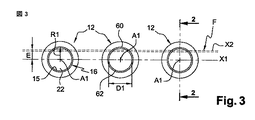
この場合、特に図3に図示されている実施形態によれば、プリフォーム12は、殺菌消毒部26のスプレーステーション28を通過し、ここでこれらのプリフォーム12は、垂直方向の位置に、移動方向X1と称される長手方向の水平方向に沿ってネック16を最も上にして整列される。
In this case, in particular according to the embodiment illustrated in FIG. 3, the
この移動方向X1は、処理を経ているプリフォーム12の軸A1を通過している。
This moving direction X1 passes through the axis A1 of the
ノズル40の平均スプレー軸A2は、処理を経ている各プリフォーム12の軸A1にほぼ平行であり、この軸A2は、規定されたずれEだけプリフォーム12の軸A1に対して径方向にずらされていることが、好都合である。
The average spray axis A2 of the
この場合垂直方向の、この平均スプレー軸A2は、移動方向X1に垂直なネック16の内径R1に沿って離心されていることが好ましい。
In this case, the average spray axis A2 in the vertical direction is preferably eccentric along the inner diameter R1 of the
この結果、ノズル40の形状により、消毒剤の流れFを下方にほぼ層流の形態ですなわち細長い垂直方向のカーテンの形態でスプレーすることが可能となる。この目的のために、ノズル40は、例えば、この流れFをスプレーするための細長いスロット又はほぼ円形の孔を有している。
As a result, the shape of the
この場合、層流Fは、スプレー平面X2と称される細長い垂直方向の平面内にあり、このスプレー平面X2は、ずれEに等しい間隔だけ移動方向X1に対して径方向にずらされている。 In this case, the laminar flow F lies in an elongated vertical plane called the spray plane X2, which is displaced in the radial direction with respect to the movement direction X1 by an interval equal to the deviation E.
この場合、消毒剤の流れFは、スプレー平面X2内を垂直に延びる無数の平均スプレー軸A2を許容する。 In this case, the disinfectant flow F allows an infinite number of average spray axes A2 extending vertically in the spray plane X2.
前記ずれEが、各プリフォーム12のネック16の内径D1の19パーセントにほぼ等しい最小Eminと、このネック16の内径D1の32パーセントにほぼ等しい最大Emaxとの間であることは好ましい。
Preferably, the offset E is between a minimum E min approximately equal to 19 percent of the inner diameter D1 of the
好都合な一実施形態によると、このずれEは、固定されて、ほぼ8ミリメートルに等しいように選択され、この結果、約25乃至42ミリメートルの間の範囲の内径D1を有するプリフォーム12のモデルにとって適している。
According to an advantageous embodiment, this deviation E is fixed and selected to be approximately equal to 8 millimeters, so that for models of
ノズル40のこのような配置のおかげで、消毒剤の流れFは、各プリフォーム12の内壁15の第1の扇形(secteur)とほぼ一致し、消毒剤の流れFは、この内壁15の扇形60をなめるように進むようにされている。
Thanks to this arrangement of the
プリフォーム12の下端20に到達すると、消毒剤の流れFは、プリフォーム12の底部を滑り、前記第1の扇形60に正反対に対向する、内壁15の第2の扇形62に沿って上昇する。
When reaching the
このように、消毒剤の流れFは、各プリフォーム12の内壁15全体を層流のタイプの流れによりほぼ通過する。
In this way, the disinfectant flow F substantially passes through the entire
このような配置により、特にプリフォーム12の底部に、前記消毒剤がこの底部に到達することを妨げうる過剰な圧力の栓が形成されることが防止される。
Such an arrangement prevents the formation of excessive pressure plugs that can prevent the disinfectant from reaching the bottom, particularly at the bottom of the
特に、前記消毒剤の、ノズル40を出た直後のスプレー速度は、層流が可能となるのに十分に低い。
In particular, the spray rate of the disinfectant immediately after leaving the
消毒剤の流れFは、この流れFの周り全体に拡散する気化した消毒剤の霧を発生させ、この消毒剤が各プリフォーム12の全領域にわたって堆積され、この結果、ネック16と、内壁15と、各プリフォーム12の外壁とが同時に無菌化すなわち消毒されることが可能となることに留意すべきである。
The disinfectant stream F generates a vaporized disinfectant mist that diffuses all around the stream F and this disinfectant is deposited over the entire area of each
本発明によるプリフォームの殺菌消毒方法を用いる装置10´の第2実施形態を、以下で図1の設備10と比較して説明する。
A second embodiment of an apparatus 10 'using the preform sterilization method according to the present invention will be described below in comparison with the
図4は、本発明による殺菌消毒されたプリフォームをブロー成形することにより殺菌消毒されたボトルを製造することができる設備10´を示している。 FIG. 4 shows an installation 10 'that can produce a sterilized bottle by blow molding a sterilized preform according to the invention.
複数のプリフォーム12は、上流側の端から下流側の端に向かって、すなわち図4を考慮すると左から右へと流れる連続流として設備10´を通って搬送される。
The plurality of
図4による設備10´は、殺菌消毒部26が第2のスプレーステーションと称される追加的なスプレーステーション29を有しているという点で図1による設備10と主に異なる。
The installation 10 'according to FIG. 4 differs mainly from the
この第2のスプレーステーションは、炉42により形成された成形部30の熱調節ステーション32の下流側に位置し、炉42は、殺菌消毒部26の活性化ステーション50の機能を結合している。
This second spray station is located downstream of the
設備10´は、上流側の端から下流側の端に向かって、第1のスプレーステーション28と称されるものと、炉42により形成された活性化ステーション50と、第2のスプレーステーション29とを有している、プリフォーム12を殺菌消毒するための第1の殺菌消毒部26と、続いて、熱調節ステーション32と成形ステーション34とを有している、プリフォーム12を成形するための成形部30を有している。
From the upstream end to the downstream end, the
この設備10´が成形部30の成形ステーション34の下流側に、充填部36と閉栓部38とを有していることは好都合である。
Conveniently, this
ステーション28、32、50、34と、部36、38とは、上述の図1のステーションと部と類似している。
殺菌消毒部26は、第1のスプレーステーション28並びに/もしくは第2のスプレーステーション29が供給を受けるために、気化した消毒剤を準備するための手段(図示されていない)を有していることが好ましい。
The
殺菌消毒部26の第2のスプレーステーション29には、第1のステーション28のように、処理の間、この場合、殺菌消毒される各プリフォーム12のネック16に向かって、蒸気のジェットの形態で消毒剤の流れFをスプレーする少なくとも1つのノズル40が設けられている。
The
このように、前記消毒剤を準備するための手段は、この消毒剤を加熱するための手段(図示されていない)と、気化した消毒剤をノズル40を介して推進させるように設計された、空気、圧搾され並びに/もしくは任意の適当な手段により殺菌消毒されていることが好都合な空気、のソース(図示されていない)とを有している。
Thus, the means for preparing the disinfectant was designed to propel the disinfectant through means (not shown) and a vaporized disinfectant through the
前記圧搾空気は、乾燥され、前記消毒剤の蒸気のための担体を形成するように方向を持った流れとして低速で流れる。 The compressed air is dried and flows at a low speed as a directional flow to form a carrier for the disinfectant vapor.
前記消毒剤が、第2のスプレーステーション29で、蒸気の状態で消毒剤を含有するガスのジェットの乾燥した蒸気のジェットが好ましい形態でプリフォーム12にスプレーされる過酸化水素又は気化した過酸化水素(H2O2)を含む化合物からなることは好ましい。
The disinfectant is sprayed onto the
本発明による殺菌消毒方法によれば、工程(a)(b)(c)が連続して実行され、プリフォーム12の内壁15とネック16とを、細菌の数を3Dすなわち3logの程度で対数的に減少させて、殺菌消毒するようにする。
According to the sterilization method according to the present invention, the steps (a), (b) and (c) are continuously performed, and the
こうして、上述のように、消毒剤の霧からなる一様なフィルムを第1のスプレーステーション26で凝縮させることにより、堆積の工程(b)が実行され、続いて、前記消毒剤を活性化させるための活性化ステーション50でプリフォーム12を加熱する工程(c)が実行される。
Thus, as described above, the deposition step (b) is carried out by condensing a uniform film of disinfectant mist at the
したがって、第1のスプレーステーション28では、消毒剤の流れFは、工程(a)にしたがって、この消毒剤の凝縮温度Tc未満の温度T1である各プリフォーム12で気化される。
Accordingly, at the
したがって、前記消毒剤を活性化するためのステーション50では、プリフォーム12は、成形温度Tm以上であることが好ましく、最も低くても活性化温度Ta以上である温度T2まで少なくとも加熱される。
Accordingly, in the
活性化ステーション50の放射加熱手段を構成する熱調節ステーション32の炉42は、各プリフォーム12を直接、成形温度Tmまで上昇させることが好都合である。この成形温度Tmは、前記消毒剤の活性化温度Taより高く、この場合、消毒剤を蒸発により消えさせるように蒸発温度Teよりも高い。
The
加熱炉42は、第1のスプレーステーション28と第2のスプレーステーション29との両方のために、熱調節ステーション32の機能と活性化ステーション50の機能とを設備10´で同時に働かせることが好都合である。
The
内壁15とネック16との両方で、細菌の数の、3D(decimal)又は3Logよりも大きな対数的な減少を達成するように、追加的な殺菌消毒工程でプリフォーム12を処理することを目的とした、殺菌消毒部26の第2のスプレーステーション29を以下でより詳細に説明する。
The objective is to treat the
プリフォーム12は、ステーション32、50の炉42により所定の温度T2まで加熱された後、これらのプリフォーム12は、続いて、第2のスプレーステーション29で追加的な殺菌消毒工程(d)を経るために、下流側に位置した第2のスプレーステーション29内に直接渡される。
After the
加熱温度T2は、例えば摂氏95度(95℃)と摂氏135度(135℃)との間の成形温度Tm以上であることが好都合である。 Conveniently, the heating temperature T2 is, for example, a molding temperature Tm between 95 degrees Celsius (95 ° C.) and 135 degrees Celsius (135 ° C.).
この場合、プリフォーム12は、第2のスプレーステーション29内で、例えば、過酸化水素(H2O2)の場合約摂氏70度(70℃)の、活性化温度Taよりも高い温度であるため、第1のスプレーステーション28において上述したような前記消毒剤の霧からなる一様なフィルムの凝縮による堆積はない。
In this case, the
これは、前記消毒剤が加熱されたプリフォーム12と接触すると瞬間的に活性化され気化し、結果として、プリフォーム12の全領域、すなわち内壁15及びネック16とプリフォーム12の外部とで、同様の殺菌効果を生ずるためである。
This is instantaneously activated and vaporized when the disinfectant comes into contact with the
第2のスプレーステーション29で実行される追加的な殺菌消毒工程のおかげで、少なくとも5D又は5Logの程度の細菌の数の対数的な減少が有利に達成される。
Thanks to an additional sterilization step carried out in the
この場合、設備10、10´、特に殺菌消毒部26を通過するプリフォーム12は、ネック16を最も上にしてすなわち「ネックアップ」位置で垂直方向に向きが設定されている。
In this case, the
変形例として、プリフォーム12は、ネック16を最も下に、すなわち「ネックダウン」で垂直に向きが設定され、プリフォーム12は、設備10、10´内で垂直方向の向きを、特にある部又はステーションから他の部又はステーションへと変化させることができる。
As a variant, the
したがって、設備10、10´は、この場合、前記「ネックアップ」位置で殺菌消毒部26のスプレーステーション28で処理されたプリフォーム12を、炉42と関連した搬送装置54により把持されるために「ネックダウン」位置に変換することができる搬送手段(図示されていない)を有している。
Thus, the
設備10、10´は、殺菌消毒部26と、成形部30と、充填部36と、閉栓部38のような処理部と共に示されてきたことに留意すべきである。
It should be noted that the
これらの部は、図示の方法により、整列されて示されているが、これらの部は、特に、カルーセル(図示されていない)のような回転装置を備えた、異なる構成で配置されていてもよい。 These parts are shown aligned according to the illustrated method, although these parts may be arranged in different configurations, particularly with a rotating device such as a carousel (not shown). Good.
Claims (12)
(a)前記プリフォーム(12)が消毒剤の凝縮温度(Tc)未満の温度(T1)であることを確認する工程と、
(b)消毒剤の流れ(F)を蒸気のジェットの形態で前記プリフォーム(12)にスプレーし、この消毒剤の霧(52)からなる実質的に一様なフィルムを、殺菌消毒される前記プリフォームの少なくとも1つの内壁(15)に凝縮により堆積させるようにする工程と、
(c)このように処理された前記プリフォーム(12)を、このプリフォームを前記消毒剤を活性化させるための温度(Ta)以上の温度(T2)にして、前記プリフォームの少なくとも内壁(15)を殺菌消毒するようにするように、放射で加熱する工程とを具備することを特徴とする殺菌消毒方法。 In a sterilization method for sterilizing plastic preforms intended to be molded by blow molding, particularly in equipment (10, 10 ') for producing a plurality of sterilized bottles (14), do it,
(A) confirming that the preform (12) is at a temperature (T1) below the condensation temperature (Tc) of the disinfectant;
(B) Spray the disinfectant stream (F) onto the preform (12) in the form of a jet of steam, and disinfect the substantially uniform film of disinfectant mist (52). Depositing on at least one inner wall (15) of the preform by condensation;
(C) The preform (12) thus treated is brought to a temperature (T2) equal to or higher than a temperature (Ta) for activating the disinfectant of the preform, and at least the inner wall ( And 15) a method of sterilizing and disinfecting by heating so as to sterilize and disinfect.
処理の間、殺菌消毒される各プリフォーム(12)に、蒸気のジェットの形態で消毒剤の流れ(F)をスプレーするための少なくとも1つのノズル(40)が設けられた、第1のステーションと称される、少なくとも1つのスプレーステーション(28)を有する殺菌消毒部(26)と、
各プリフォーム(12)を成形温度(Tm)にすることを目的とする炉(42)を備えた熱調節ステーション(32)と、殺菌消毒されたボトル(14)を製造することができる成形ステーション(34)とを有する成形部(30)とを具備するタイプの設備(10、10´)において、
前記第1の、スプレーステーション(28)で、消毒剤の前記流れ(F)は、各プリフォーム(12)で気化され、各プリフォームの温度(T1)は、この消毒剤の凝縮温度(Tc)未満であり、前記消毒剤の霧(52)からなる実質的に一様なフィルムが、殺菌消毒される前記内壁(15)で凝縮により堆積されるようにされ、また、前記殺菌消毒部(26)は、このように処理された各プリフォーム(12)を、このプリフォーム(12)の内壁(15)を殺菌消毒するように、前記活性温度(Ta)以上の温度(T2)に加熱するための炉(42)を構成する放射加熱手段を有する、前記消毒剤を活性化するための活性化ステーション(50)を有していることを特徴とする設備(10、10´)。 Manufacturing a sterilized bottle (14) from a plastic preform (12) by performing a method of sterilizing a plurality of said preforms (12) according to any one of the preceding claims Equipment (10, 10 ') for carrying out the process (10, 10') as a continuous flow in which the preform (12) moves from the upstream end toward the downstream end. The type that is transported, continuously, at least,
A first station in which each preform (12) to be sterilized during processing is provided with at least one nozzle (40) for spraying a disinfectant stream (F) in the form of a jet of steam. A sterilization section (26) having at least one spray station (28), referred to as
A heat control station (32) with a furnace (42) aimed at bringing each preform (12) to the molding temperature (Tm) and a molding station capable of producing a sterilized bottle (14). In the type of equipment (10, 10 ') comprising a molding part (30) having (34)
In the first, spray station (28), the flow (F) of disinfectant is vaporized in each preform (12), and the temperature (T1) of each preform is the condensation temperature (Tc) of this disinfectant. ) And a substantially uniform film of the disinfectant mist (52) is allowed to deposit by condensation on the inner wall (15) to be sterilized, and the sterilization part ( 26) heating each preform (12) thus treated to a temperature (T2) equal to or higher than the activation temperature (Ta) so as to sterilize and disinfect the inner wall (15) of the preform (12). A facility (10, 10 ') comprising an activation station (50) for activating the disinfectant, comprising radiant heating means constituting a furnace (42) for performing the above.
Applications Claiming Priority (2)
| Application Number | Priority Date | Filing Date | Title |
|---|---|---|---|
| FR0551752A FR2887526B1 (en) | 2005-06-24 | 2005-06-24 | PROCESS FOR STERILIZING PREFORMS AND SYSTEM PRODUCING STERILE BOTTLES THEREFROM |
| FR0551752 | 2005-06-24 |
Related Parent Applications (1)
| Application Number | Title | Priority Date | Filing Date |
|---|---|---|---|
| JP2008517457A Division JP4885951B2 (en) | 2005-06-24 | 2006-06-08 | Methods for sterilizing preforms and equipment for producing sterilized bottles from these preforms |
Publications (1)
| Publication Number | Publication Date |
|---|---|
| JP2012082013A true JP2012082013A (en) | 2012-04-26 |
Family
ID=35788387
Family Applications (2)
| Application Number | Title | Priority Date | Filing Date |
|---|---|---|---|
| JP2008517457A Active JP4885951B2 (en) | 2005-06-24 | 2006-06-08 | Methods for sterilizing preforms and equipment for producing sterilized bottles from these preforms |
| JP2011222991A Pending JP2012082013A (en) | 2005-06-24 | 2011-10-07 | Method for sterilizing preform and installation for producing sterile bottle from these preform |
Family Applications Before (1)
| Application Number | Title | Priority Date | Filing Date |
|---|---|---|---|
| JP2008517457A Active JP4885951B2 (en) | 2005-06-24 | 2006-06-08 | Methods for sterilizing preforms and equipment for producing sterilized bottles from these preforms |
Country Status (10)
| Country | Link |
|---|---|
| US (1) | US8092757B2 (en) |
| EP (1) | EP1896245B2 (en) |
| JP (2) | JP4885951B2 (en) |
| CN (1) | CN101203370B (en) |
| AT (1) | ATE431238T1 (en) |
| DE (1) | DE602006006830D1 (en) |
| ES (1) | ES2323812T5 (en) |
| FR (1) | FR2887526B1 (en) |
| PT (1) | PT1896245E (en) |
| WO (1) | WO2006136499A1 (en) |
Cited By (3)
| Publication number | Priority date | Publication date | Assignee | Title |
|---|---|---|---|---|
| JP2015063143A (en) * | 2014-12-26 | 2015-04-09 | キリンビバレッジ株式会社 | Blow molding system, production line including the same, and preform conveyor used in both thereof |
| JP2016141400A (en) * | 2015-01-29 | 2016-08-08 | 大日本印刷株式会社 | Sterilization method and sterilization device for composite preform, sterilization method and sterilization device for composite container, composite preform and composite container |
| JP2020508940A (en) * | 2017-02-28 | 2020-03-26 | エスアイジー テクノロジー アーゲーSIG Technology AG | Method and filling device for filling a package that is open on one side |
Families Citing this family (71)
| Publication number | Priority date | Publication date | Assignee | Title |
|---|---|---|---|---|
| FR2887525B1 (en) * | 2005-06-24 | 2007-09-07 | Sidel Sas | INSTALLATION PRODUCING STERILE BOTTLES BY BLOWING FROM STERILIZED PREFORMS |
| FR2887526B1 (en) * | 2005-06-24 | 2007-09-07 | Sidel Sas | PROCESS FOR STERILIZING PREFORMS AND SYSTEM PRODUCING STERILE BOTTLES THEREFROM |
| FR2907684B1 (en) * | 2006-10-26 | 2009-12-04 | Sidel Participations | METHOD OF STERILIZING A PREFORM, INSTALLATION AND OVEN FOR MANUFACTURING STERILE CONTAINERS ACCORDING TO THIS PROCESS |
| FR2910329B1 (en) * | 2006-12-20 | 2009-04-17 | Sidel Participations | METHOD AND DEVICE FOR STERILIZING PREFORMS |
| DE102007017938C5 (en) * | 2007-04-13 | 2017-09-21 | Khs Gmbh | Container manufacturing apparatus and mold production method |
| JP5141185B2 (en) * | 2007-10-26 | 2013-02-13 | 澁谷工業株式会社 | Container sterilizer |
| JP5359020B2 (en) * | 2008-05-14 | 2013-12-04 | 大日本印刷株式会社 | Aseptic filling method |
| CN103625699B (en) * | 2008-05-20 | 2016-05-11 | 大日本印刷株式会社 | Beverage fill method and device |
| DE102008030156A1 (en) * | 2008-06-27 | 2009-12-31 | Krones Ag | Apparatus and method for producing plastic containers |
| EP2143545A1 (en) * | 2008-07-07 | 2010-01-13 | Nestec S.A. | Method and apparatus for packaging a liquid food product |
| DE102008038141A1 (en) | 2008-08-18 | 2010-02-25 | Krones Ag | Device for forming plastic preforms with sterile space |
| CN104944346B (en) * | 2009-02-06 | 2017-08-25 | 大日本印刷株式会社 | Beverage filling method and beverage filling device |
| JP5585128B2 (en) * | 2009-03-10 | 2014-09-10 | 大日本印刷株式会社 | Beverage filling method and apparatus |
| DE102009041215A1 (en) | 2009-09-11 | 2011-03-24 | Krones Ag | Method and apparatus for stretch blow molding or blow molding and filling sterile containers |
| JP5831673B2 (en) * | 2010-01-22 | 2015-12-09 | 東洋製罐株式会社 | Spatial surface sterilization method |
| DE102010020996A1 (en) | 2010-05-11 | 2011-11-17 | Khs Corpoplast Gmbh | Method and device for sterilizing and device for blow molding of containers |
| DE102010022131A1 (en) * | 2010-05-20 | 2011-11-24 | Krones Ag | Sterilizable blow mold |
| FR2961125B1 (en) | 2010-06-10 | 2012-07-13 | Sidel Participations | AIR RECYCLING METHOD COMPRISING A STERILIZING AGENT AND CONTAINER MANUFACTURING PLANT COMPRISING AN AIR RECYCLING CIRCUIT |
| IT1402423B1 (en) * | 2010-06-11 | 2013-09-04 | Gea Procomac Spa | FORMING DEVICE FOR A CONTAINER OBTAINED FROM A PREFORM IN PLASTIC MATERIAL, FORMING METHOD AND FORMING MACHINE |
| DE102010026166A1 (en) * | 2010-07-01 | 2012-01-05 | Khs Corpoplast Gmbh | Method and device for sterilizing and device for blow molding of containers |
| DE102010032336A1 (en) | 2010-07-22 | 2012-01-26 | Khs Corpoplast Gmbh | Method and device for sterilizing and device for blow molding of containers |
| DE102010042958A1 (en) * | 2010-10-26 | 2012-05-10 | Krones Aktiengesellschaft | Plant and process for the continuous production of preforms |
| DE102010056450A1 (en) | 2010-12-23 | 2012-06-28 | Khs Corpoplast Gmbh | Method and device for blow-molding sterile containers |
| DE102011008132A1 (en) | 2011-01-04 | 2012-07-05 | Khs Corpoplast Gmbh | Method and device for blow-molding sterile containers |
| DE102011104024A1 (en) | 2011-06-06 | 2012-12-06 | Khs Corpoplast Gmbh | Method and device for sterilizing and device for blow molding of containers |
| WO2013021882A1 (en) | 2011-08-05 | 2013-02-14 | 大日本印刷株式会社 | Beverage filling method and device |
| CN103917453B (en) | 2011-10-25 | 2016-03-23 | 大日本印刷株式会社 | Beverage fill method and device thereof |
| DE102011056437A1 (en) * | 2011-12-14 | 2013-06-20 | Krones Ag | Device for treating plastic containers, beverage filling plant and / or beverage container manufacturing plant and method for the conversion of plastic preforms and use of heating means of transport |
| FR2984751B1 (en) | 2011-12-21 | 2014-08-29 | Sidel Participations | DECONTAMINATION DEVICE BY IRRADIATION OF THE INTERIOR OF AN OBJECT |
| JP5962352B2 (en) * | 2012-09-05 | 2016-08-03 | 大日本印刷株式会社 | Preform sterilization method and contents filling method and apparatus |
| ITPR20120048A1 (en) * | 2012-07-25 | 2014-01-26 | Gea Procomac Spa | METHOD AND FORMAT OF FORMING A CONTAINER |
| ITPR20120049A1 (en) * | 2012-07-25 | 2014-01-26 | Gea Procomac Spa | SYSTEM AND METHOD OF STERILIZATION OF A PREFORM |
| WO2014032731A1 (en) * | 2012-08-31 | 2014-03-06 | Sa Des Eaux Minerales D'evian Saeme | Method of making a bottle made of fdca and diol monomers and apparatus for implementing such method |
| DE102012112946A1 (en) | 2012-12-21 | 2014-06-26 | Krones Ag | Dividing delay star for transporting plastic containers |
| DE102013101407A1 (en) * | 2013-02-13 | 2014-08-14 | Khs Gmbh | Process for packaging liquid products under pressure in bottles of plastic or similar containers |
| JP5610022B2 (en) * | 2013-04-05 | 2014-10-22 | 大日本印刷株式会社 | Aseptic filling equipment |
| US10086554B2 (en) | 2013-04-24 | 2018-10-02 | Discma Ag | Method and machine for manufacturing plastic containers |
| DE102013013590A1 (en) | 2013-08-19 | 2015-02-19 | Khs Corpoplast Gmbh | Method and apparatus for blow molding at least partially sterile containers |
| DE102013013591A1 (en) | 2013-08-19 | 2015-02-19 | Khs Corpoplast Gmbh | Method and device for the blow-molding production of at least partially sterile containers |
| DE102013013592A1 (en) | 2013-08-19 | 2015-02-19 | Khs Corpoplast Gmbh | Apparatus and method for producing sterile containers |
| DE102013013589A1 (en) | 2013-08-19 | 2015-02-19 | Khs Corpoplast Gmbh | Apparatus and method for producing sterile containers |
| JP6747490B2 (en) * | 2013-11-14 | 2020-08-26 | 大日本印刷株式会社 | Preform sterilization method and device |
| JP6439920B2 (en) | 2013-11-14 | 2018-12-19 | 大日本印刷株式会社 | Bottle sterilization method and apparatus |
| JP6439921B2 (en) * | 2013-11-14 | 2018-12-19 | 大日本印刷株式会社 | Bottle sterilization method and apparatus |
| JP6439919B2 (en) * | 2013-11-14 | 2018-12-19 | 大日本印刷株式会社 | Preform sterilization method and apparatus |
| DE102013019169A1 (en) | 2013-11-18 | 2015-05-21 | Khs Gmbh | Apparatus and method for producing sterile containers |
| DE102014010283A1 (en) | 2014-07-13 | 2016-01-14 | Khs Corpoplast Gmbh | Method and blow molding machine for the blow-molding production of at least partially sterile containers |
| JP5804165B2 (en) * | 2014-09-04 | 2015-11-04 | 大日本印刷株式会社 | Aseptic filling equipment |
| JP5804164B2 (en) * | 2014-09-04 | 2015-11-04 | 大日本印刷株式会社 | Aseptic filling method and apparatus |
| JP6079734B2 (en) * | 2014-09-04 | 2017-02-15 | 大日本印刷株式会社 | Aseptic filling method and apparatus |
| JP6007954B2 (en) * | 2014-09-04 | 2016-10-19 | 大日本印刷株式会社 | Aseptic filling method and apparatus |
| JP5880647B2 (en) * | 2014-09-04 | 2016-03-09 | 大日本印刷株式会社 | Aseptic filling method and apparatus |
| EP3199462B1 (en) | 2014-09-25 | 2022-05-04 | Dai Nippon Printing Co., Ltd. | Method for sterilizing preform and resin container |
| FR3028204B1 (en) | 2014-11-10 | 2017-04-21 | Sidel Participations | "THERMOPLASTIC CONTAINER MANUFACTURING FACILITY INCORPORATING A GRINDING DEVICE AND SUCH A GRINDING DEVICE" |
| JP6459471B2 (en) * | 2014-12-15 | 2019-01-30 | 大日本印刷株式会社 | Blow molding method, blow molding apparatus, composite preform and composite container |
| JP5967245B2 (en) * | 2015-04-02 | 2016-08-10 | 大日本印刷株式会社 | Soft drink filling method and apparatus |
| JP6149919B2 (en) * | 2015-11-26 | 2017-06-21 | 大日本印刷株式会社 | Beverage filling method and apparatus |
| EP3393529B1 (en) * | 2015-12-22 | 2021-03-17 | Sidel Participations | Method of sterilizing the means of stretching a container moulding device and container manufacturing plant |
| FR3051675B1 (en) | 2016-05-25 | 2019-09-27 | Sidel Participations | METHOD FOR PROCESSING HOLLOW BODIES AND FACILITY FOR MANUFACTURING CONTAINERS INTEGRATING SUCH A METHOD |
| WO2017221991A1 (en) | 2016-06-24 | 2017-12-28 | 大日本印刷株式会社 | Method and device for sterilizing preform |
| JP6372536B2 (en) | 2016-09-23 | 2018-08-15 | 大日本印刷株式会社 | Aseptic filling machine |
| FR3059904B1 (en) * | 2016-12-12 | 2019-05-17 | Sidel Participations | METHOD FOR DECONTAMINATING AN EXTERNAL SURFACE OF A PREFORM IN THERMOPLASTIC MATERIAL |
| FR3054474B1 (en) | 2017-02-16 | 2018-08-17 | Sidel Participations | DEVICE AND METHOD FOR DEFLUSTING THE INTERIOR OF AT LEAST ONE PREFORM |
| JP6859740B2 (en) * | 2017-02-22 | 2021-04-14 | 東洋製罐株式会社 | Aseptic filling system and aseptic filling method |
| MX2019014355A (en) * | 2017-05-30 | 2020-10-01 | David Melrose Design Ltd | Hybrid method and system for processing containers. |
| IT201700089679A1 (en) * | 2017-08-03 | 2019-02-03 | Gea Procomac Spa | SYSTEM TO PRODUCE STERILE VESSELS, BOTTLING SYSTEM INCLUDING THIS EQUIPMENT AND METHOD TO PRODUCE A STERILE CONTAINER |
| JP6455574B1 (en) * | 2017-09-05 | 2019-01-23 | 大日本印刷株式会社 | Blow molding machine sterilization method and blow molding machine |
| IT201900013053A1 (en) * | 2019-07-26 | 2021-01-26 | Gea Procomac Spa | METHOD AND APPARATUS FOR PRODUCTION OF STERILE CONTAINERS AND BOTTLING PLANT INCLUDING THIS APPARATUS |
| CN111231273B (en) * | 2020-01-19 | 2021-06-18 | 江苏新美星包装机械股份有限公司 | Preform disinfection method and bottle making equipment |
| DE102020109455A1 (en) | 2020-04-03 | 2021-10-07 | Khs Corpoplast Gmbh | Method and device for sterilizing preforms or containers formed therefrom |
| CN111658803A (en) * | 2020-06-03 | 2020-09-15 | 上海东富龙爱瑞思科技有限公司 | Quick hydrogen peroxide sterilization pass box |
Citations (3)
| Publication number | Priority date | Publication date | Assignee | Title |
|---|---|---|---|---|
| JP2001510104A (en) * | 1997-07-18 | 2001-07-31 | シデル・エス・アー | Manufacturing method of sterilization container made of plastic material and apparatus for performing |
| JP2006509690A (en) * | 2002-12-13 | 2006-03-23 | テトラ ラバル ホールデイングス エ フイナンス ソシエテ アノニム | Control device and method for sterilizer |
| JP2008546605A (en) * | 2005-06-24 | 2008-12-25 | スィデル・パルティスィパスィヨン | Methods for sterilizing preforms and equipment for producing sterilized bottles from these preforms |
Family Cites Families (16)
| Publication number | Priority date | Publication date | Assignee | Title |
|---|---|---|---|---|
| US4512951A (en) * | 1980-12-30 | 1985-04-23 | American Sterilizer Company | Hydrogen peroxide liquid film sterilization method |
| US4512591A (en) | 1982-07-06 | 1985-04-23 | Plante Jean Paul | Hand truck |
| JP2885869B2 (en) * | 1990-04-09 | 1999-04-26 | 大日本印刷株式会社 | Blow molding and filling method for aseptic containers |
| JPH10323385A (en) | 1997-05-23 | 1998-12-08 | Wakayama Nookiyoo Shokuhin Kogyo Kk | Sterilizing method for vessel |
| FR2766169B1 (en) * | 1997-07-17 | 1999-10-01 | Sidel Sa | THERMOPLASTIC CONTAINER DEFLECTION STERILIZATION INSTALLATION |
| US6039922A (en) | 1997-08-15 | 2000-03-21 | Tetra Laval Holdings & Finance, Sa | UV radiation and vapor-phase hydrogen peroxide sterilization packaging |
| FR2774912B1 (en) * | 1998-02-16 | 2000-09-01 | Sidel Sa | METHOD FOR STERILIZING HOLLOW BODIES AND DEVICE FOR IMPLEMENTING SAME |
| SE511861C2 (en) * | 1998-04-07 | 1999-12-06 | Tetra Laval Holdings & Finance | Method and apparatus for producing a sterile packaging container |
| JPH11290226A (en) | 1998-04-14 | 1999-10-26 | Yasuto Fukushima | Device for preventing outflow of washed rice |
| JP4012653B2 (en) * | 1999-07-29 | 2007-11-21 | 大日本印刷株式会社 | PET bottle sterilization method and apparatus |
| DE19949692A1 (en) | 1999-10-15 | 2001-04-19 | Gea Finnah Gmbh | Sterilization of temperature-sensitive especially polyethylene terephthalate bottles moving on a conveyor, using a peroxide aerosol and sterile air |
| JP2001212874A (en) * | 2000-02-02 | 2001-08-07 | Shikoku Kakoki Co Ltd | Method for molding and filling sterile container |
| US7186374B2 (en) * | 2001-02-16 | 2007-03-06 | Steris Inc. | Vapor phase decontamination of containers |
| DE10114758B4 (en) | 2001-03-20 | 2013-01-31 | Ptm Packaging Tools Machinery Pte. Ltd. | Method for sterilizing containers |
| US20050226796A1 (en) * | 2002-02-12 | 2005-10-13 | Atsushi Hayakawa | Method of sterilization for container, apparatus using therefor, and heat treatment for container |
| FR2838076B1 (en) * | 2002-04-04 | 2005-03-04 | Sidel Sa | METHOD AND INSTALLATION FOR DECONTAMINATION OF PREFORMS |
-
2005
- 2005-06-24 FR FR0551752A patent/FR2887526B1/en not_active Expired - Fee Related
-
2006
- 2006-06-08 US US11/993,494 patent/US8092757B2/en active Active
- 2006-06-08 AT AT06763581T patent/ATE431238T1/en not_active IP Right Cessation
- 2006-06-08 WO PCT/EP2006/063006 patent/WO2006136499A1/en active Application Filing
- 2006-06-08 EP EP06763581.3A patent/EP1896245B2/en active Active
- 2006-06-08 PT PT06763581T patent/PT1896245E/en unknown
- 2006-06-08 CN CN2006800223821A patent/CN101203370B/en active Active
- 2006-06-08 JP JP2008517457A patent/JP4885951B2/en active Active
- 2006-06-08 ES ES06763581T patent/ES2323812T5/en active Active
- 2006-06-08 DE DE602006006830T patent/DE602006006830D1/en active Active
-
2011
- 2011-10-07 JP JP2011222991A patent/JP2012082013A/en active Pending
Patent Citations (3)
| Publication number | Priority date | Publication date | Assignee | Title |
|---|---|---|---|---|
| JP2001510104A (en) * | 1997-07-18 | 2001-07-31 | シデル・エス・アー | Manufacturing method of sterilization container made of plastic material and apparatus for performing |
| JP2006509690A (en) * | 2002-12-13 | 2006-03-23 | テトラ ラバル ホールデイングス エ フイナンス ソシエテ アノニム | Control device and method for sterilizer |
| JP2008546605A (en) * | 2005-06-24 | 2008-12-25 | スィデル・パルティスィパスィヨン | Methods for sterilizing preforms and equipment for producing sterilized bottles from these preforms |
Cited By (5)
| Publication number | Priority date | Publication date | Assignee | Title |
|---|---|---|---|---|
| JP2015063143A (en) * | 2014-12-26 | 2015-04-09 | キリンビバレッジ株式会社 | Blow molding system, production line including the same, and preform conveyor used in both thereof |
| JP2016141400A (en) * | 2015-01-29 | 2016-08-08 | 大日本印刷株式会社 | Sterilization method and sterilization device for composite preform, sterilization method and sterilization device for composite container, composite preform and composite container |
| JP2020508940A (en) * | 2017-02-28 | 2020-03-26 | エスアイジー テクノロジー アーゲーSIG Technology AG | Method and filling device for filling a package that is open on one side |
| JP7214304B2 (en) | 2017-02-28 | 2023-01-30 | エスアイジー コンビブロック サービシズ アクチェンゲゼルシャフト | Method and filling device for filling open-sided packages |
| US11780627B2 (en) | 2017-02-28 | 2023-10-10 | Sig Technology Ag | Method and filling machine for filling packages that are open on one side |
Also Published As
| Publication number | Publication date |
|---|---|
| ES2323812T3 (en) | 2009-07-24 |
| FR2887526A1 (en) | 2006-12-29 |
| ATE431238T1 (en) | 2009-05-15 |
| EP1896245B2 (en) | 2013-06-26 |
| CN101203370B (en) | 2010-05-19 |
| ES2323812T5 (en) | 2013-10-01 |
| DE602006006830D1 (en) | 2009-06-25 |
| CN101203370A (en) | 2008-06-18 |
| EP1896245A1 (en) | 2008-03-12 |
| PT1896245E (en) | 2009-06-01 |
| JP2008546605A (en) | 2008-12-25 |
| EP1896245B1 (en) | 2009-05-13 |
| US8092757B2 (en) | 2012-01-10 |
| FR2887526B1 (en) | 2007-09-07 |
| JP4885951B2 (en) | 2012-02-29 |
| US20100047120A1 (en) | 2010-02-25 |
| WO2006136499A1 (en) | 2006-12-28 |
Similar Documents
| Publication | Publication Date | Title |
|---|---|---|
| JP4885951B2 (en) | Methods for sterilizing preforms and equipment for producing sterilized bottles from these preforms | |
| JP4806018B2 (en) | Equipment for producing sterilized bottles by blow molding sterilized preforms | |
| JP5311441B2 (en) | Method and apparatus for sterilizing preforms | |
| CN101528271B (en) | Furnace and equipment for producing sterile vessels from decontaminated preforms of a thermoplastic material | |
| JP3780165B2 (en) | Hollow body sterilization method and equipment | |
| US6919043B2 (en) | Method of sterilization for container, apparatus using therefor and heat treatment for container | |
| US9272060B2 (en) | Method for pre-treating preforms and blow molding apparatus for pre-treating and blow molding preforms into containers | |
| JP5359020B2 (en) | Aseptic filling method | |
| WO2015137480A1 (en) | Method and device for sterilizing container | |
| WO2021143099A1 (en) | Preform disinfection method and bottle manufacturing device | |
| US20050226796A1 (en) | Method of sterilization for container, apparatus using therefor, and heat treatment for container | |
| JP6909239B2 (en) | Processes and plants for container manufacturing and processing | |
| JP6079734B2 (en) | Aseptic filling method and apparatus | |
| CN110785278B (en) | Preform heating device and preform heating method | |
| JP2018131272A (en) | Aseptic filling machine and aseptic filling method | |
| JP6007954B2 (en) | Aseptic filling method and apparatus | |
| JP2015013482A (en) | Aseptic filling method and apparatus | |
| CN110072561A (en) | The decontamination method of the outer surface of the preform of thermoplastic material | |
| JP2018118789A (en) | Aseptic filling machine and aseptic filling method |
Legal Events
| Date | Code | Title | Description |
|---|---|---|---|
| A977 | Report on retrieval |
Free format text: JAPANESE INTERMEDIATE CODE: A971007 Effective date: 20130111 |
|
| A131 | Notification of reasons for refusal |
Free format text: JAPANESE INTERMEDIATE CODE: A132 Effective date: 20130305 |
|
| A02 | Decision of refusal |
Free format text: JAPANESE INTERMEDIATE CODE: A02 Effective date: 20131008 |