JP2012061663A - Image forming apparatus, image forming method, pattern generating method, and image forming program - Google Patents
Image forming apparatus, image forming method, pattern generating method, and image forming program Download PDFInfo
- Publication number
- JP2012061663A JP2012061663A JP2010206606A JP2010206606A JP2012061663A JP 2012061663 A JP2012061663 A JP 2012061663A JP 2010206606 A JP2010206606 A JP 2010206606A JP 2010206606 A JP2010206606 A JP 2010206606A JP 2012061663 A JP2012061663 A JP 2012061663A
- Authority
- JP
- Japan
- Prior art keywords
- dot
- image forming
- pattern
- dots
- forming apparatus
- Prior art date
- Legal status (The legal status is an assumption and is not a legal conclusion. Google has not performed a legal analysis and makes no representation as to the accuracy of the status listed.)
- Pending
Links
Images


Classifications
-
- B—PERFORMING OPERATIONS; TRANSPORTING
- B41—PRINTING; LINING MACHINES; TYPEWRITERS; STAMPS
- B41J—TYPEWRITERS; SELECTIVE PRINTING MECHANISMS, i.e. MECHANISMS PRINTING OTHERWISE THAN FROM A FORME; CORRECTION OF TYPOGRAPHICAL ERRORS
- B41J29/00—Details of, or accessories for, typewriters or selective printing mechanisms not otherwise provided for
- B41J29/38—Drives, motors, controls or automatic cut-off devices for the entire printing mechanism
-
- B—PERFORMING OPERATIONS; TRANSPORTING
- B41—PRINTING; LINING MACHINES; TYPEWRITERS; STAMPS
- B41J—TYPEWRITERS; SELECTIVE PRINTING MECHANISMS, i.e. MECHANISMS PRINTING OTHERWISE THAN FROM A FORME; CORRECTION OF TYPOGRAPHICAL ERRORS
- B41J2/00—Typewriters or selective printing mechanisms characterised by the printing or marking process for which they are designed
- B41J2/005—Typewriters or selective printing mechanisms characterised by the printing or marking process for which they are designed characterised by bringing liquid or particles selectively into contact with a printing material
- B41J2/01—Ink jet
- B41J2/21—Ink jet for multi-colour printing
- B41J2/2132—Print quality control characterised by dot disposition, e.g. for reducing white stripes or banding
- B41J2/2139—Compensation for malfunctioning nozzles creating dot place or dot size errors
Landscapes
- Engineering & Computer Science (AREA)
- Quality & Reliability (AREA)
- Ink Jet (AREA)
Abstract
【課題】線画のライン形状を崩さずに吐出不良のノズルによるスジを低減させることが可能な画像形成装置、画像形成方法、パターン生成方法及び画像形成プログラムを提供することを目的としている。
【解決手段】入力された画像データに基づき複数のノズルからインク液滴を吐出させて記録媒体にドットを形成する記録ヘッドを有する画像形成装置であって、吐出不良の前記ノズルの検知する検知手段と、前記吐出不良の前記ノズルにより形成されるべき形成予定ドットの位置を含む注目領域を設定する注目領域設定手段と、前記吐出不良の前記ノズルが検知されたとき、前記注目領域内に前記画像データにより表現される線画の傾きと、前記注目領域内にあるドットのサイズを示す値とに基づき前記注目領域におけるドットの再配置を行う再配置手段と、を有する。
【選択図】図10An object of the present invention is to provide an image forming apparatus, an image forming method, a pattern generating method, and an image forming program capable of reducing streaks due to defective nozzles without destroying the line shape of a line drawing.
An image forming apparatus having a recording head that forms dots on a recording medium by ejecting ink droplets from a plurality of nozzles based on input image data, and detecting means for detecting the nozzle having a defective ejection. And an attention area setting means for setting an attention area including a position of a dot to be formed to be formed by the nozzle having the ejection failure, and the image in the attention area when the nozzle having the ejection failure is detected. Rearrangement means for rearranging dots in the attention area based on the inclination of the line drawing represented by the data and a value indicating the size of the dot in the attention area.
[Selection] Figure 10
Description
本発明は、入力された画像データに基づき複数のノズルからインク液滴を吐出させて記録媒体にドットを形成する記録ヘッドを有する画像形成装置、画像形成方法、パターン生成方法及び画像形成プログラムに関する。 The present invention relates to an image forming apparatus, an image forming method, a pattern generating method, and an image forming program having a recording head that forms dots on a recording medium by ejecting ink droplets from a plurality of nozzles based on input image data.
画像データを処理する画像処理装置として、パーソナルコンピュータやワークステーション等がある。画像処理装置では、画像処理装置上で動作するアプリケーションソフトによって種々のオブジェクト(文字や塗り、線、写真)からなる画像データが作成される。 Examples of image processing apparatuses that process image data include personal computers and workstations. In the image processing apparatus, image data composed of various objects (characters, paint, lines, and photographs) is created by application software that operates on the image processing apparatus.
この画像データを画像として形成し出力する画像形成装置としては、プリンタやファクシミリ、複写装置、またこれらの複合機等がある。画像形成方法としては例えば、インクジェット記録方式や電子写真方式などがあり、記録液(インク)やトナーなどの画像形成材を使用して画像を形成する。 Examples of the image forming apparatus that forms and outputs the image data as an image include a printer, a facsimile machine, a copying apparatus, and a multifunction machine of these. Examples of the image forming method include an ink jet recording method and an electrophotographic method, and an image is formed using an image forming material such as a recording liquid (ink) or toner.
画像形成装置の一つとして、インクジェット方式によりディジタル画像記録を行うインクジェット記録装置が普及している。一般に、インクジェット記録装置には、記録手段であるプリントヘッド、インクタンクを搭載するキャリッジ、記録紙を搬送する搬送手段及びこれらを制御する制御手段が具備されている。現在のところ、インクジェット記録方式としていわゆるシリアルヘッド方式、ラインヘッド方式がある。 As one of the image forming apparatuses, an ink jet recording apparatus that performs digital image recording by an ink jet method is widely used. In general, an ink jet recording apparatus includes a print head as a recording unit, a carriage on which an ink tank is mounted, a transport unit that transports recording paper, and a control unit that controls these. At present, there are so-called serial head method and line head method as ink jet recording methods.
シリアルヘッド方式は、複数の吐出口からインク液滴を吐出させるプリントヘッドを記録紙の搬送方向(副走査方向)と直交する方向(主走査方向)にシリアルスキャンさせ、一方で非記録時に所定の量で間欠搬送するものである。ラインヘッド方式は、印字幅分のプリントヘッドあるいは複数のプリントヘッドが並び、記録紙を1方向に搬送して画像形成する。更に、カラー対応のインクジェット記録装置の場合には、複数色のプリントヘッドから吐出されるインク液滴の重ね合わせによりカラー画像を形成している。 In the serial head method, a print head that discharges ink droplets from a plurality of discharge ports is serially scanned in a direction (main scanning direction) perpendicular to the recording paper conveyance direction (sub-scanning direction), while a predetermined time is set when non-recording is performed. It is intermittently conveyed by the amount. In the line head system, a print head or a plurality of print heads corresponding to the print width are arranged, and a recording sheet is conveyed in one direction to form an image. Furthermore, in the case of a color-compatible inkjet recording apparatus, a color image is formed by superimposing ink droplets ejected from a plurality of color print heads.
ラインヘッド方式は1スキャン(走査)で画像を完成させる。また、シリアルヘッド方式でも多くの場合、1スキャン(走査)の画像形成方式が選択できるようになっている。 In the line head method, an image is completed in one scan (scan). In many cases, the serial head method can select an image forming method for one scan.
この1スキャンによる記録は、画像形成時間が短いという長所がある。一方、プリントヘッドのノズルに欠損があると、ドット着弾位置のずれが生じたり、ドットが形成できずにスジが発生するという短所がある。 This one-scan recording has the advantage that the image formation time is short. On the other hand, if there is a defect in the nozzle of the print head, there are disadvantages that the dot landing position shifts or that dots cannot be formed and streaks occur.
上記問題を解決するために、例えば特許文献1には、故障したノズルに隣接するノズルによるドットの径を大きくするように駆動を切り換えることで故障ノズルによるスジを低減することが開示されている。また特許文献2にも、不吐出により発生する記録画像の白スジ等の画像ムラを解消することが開示されている。
In order to solve the above problem, for example,
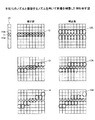
特許文献1に開示された手法により、画像を補整した場合、図1に示すようになる。図1は、不吐出のノズルと隣接するノズルを用いて画像を補整した例を示す図である。
When the image is corrected by the method disclosed in
図1では、8ドットのプリンタヘッド10のうち、ノズル11が不吐出である場合の例である。画像12、13、14は、ノズル11から吐出されるドットにより形成されるべき画像を示す。図1ではノズル11が不吐出であるため、画像12、13、14に示す画像が画像欠け(スジ)となる。画像12A、13A、14Aは、ノズル11が形成すべき画像12、13、14を、ノズル11と隣接するノズル11A,11Bから吐出されるドットを用いて補整した画像の例である。
FIG. 1 shows an example in which the nozzle 11 of the 8-
上記従来の技術では、不吐出のノズルに隣接するノズルから吐出されるドットを用いて画像を補整している。このため例えば図1に示すように不吐出のノズルにより形成する画像が細線である場合、線の太さが変わったり、線にがたつきが生じたりする。 In the above conventional technique, an image is corrected using dots ejected from nozzles adjacent to non-ejection nozzles. For this reason, for example, as shown in FIG. 1, when the image formed by the non-ejection nozzle is a thin line, the thickness of the line is changed or the line is wobbled.
例えば図1の画像12Aでは、ノズル11の両隣のノズル11A,11Bから吐出されるドットを大きくして画像12を補整しているため、線の太さが変わる。画像13Aでは、線のノズル11のドットに対応する画像をノズル11A,11Bからのドットで補整しているため、線の太さが一部変わり、線にがたつきが生じる。画像14Aも同様に線の太さが一部変わったり、線にがたつきが生じる。
For example, in the
本発明は、上記事情を鑑みてこれを解決すべくなされたものであり、線画のライン形状を崩さずに吐出不良のノズルによるスジを低減させることが可能な画像形成装置、画像形成方法、パターン生成方法及び画像形成プログラムを提供することを目的としている。 The present invention has been made in view of the above circumstances, and is an image forming apparatus, an image forming method, and a pattern that can reduce streaks caused by defective nozzles without destroying the line shape of a line drawing. An object of the present invention is to provide a generation method and an image forming program.
本発明は、上記目的を達成するために、以下の如き構成を採用した。 The present invention employs the following configuration in order to achieve the above object.
本発明は、入力された画像データに基づき複数のノズルからインク液滴を吐出させて記録媒体にドットを形成する記録ヘッドを有する画像形成装置であって、吐出不良の前記ノズルの検知する検知手段と、前記吐出不良の前記ノズルにより形成されるべき形成予定ドットの位置を含む注目領域を設定する注目領域設定手段と、前記吐出不良の前記ノズルが検知されたとき、前記注目領域内に前記画像データにより表現される線画の傾きと、前記注目領域内にあるドットのサイズを示す値とに基づき前記注目領域におけるドットの再配置を行う再配置手段と、を有する。 The present invention is an image forming apparatus having a recording head that forms dots on a recording medium by ejecting ink droplets from a plurality of nozzles based on inputted image data, and detecting means for detecting the nozzles with defective ejection And an attention area setting means for setting an attention area including a position of a dot to be formed to be formed by the nozzle having the ejection failure, and the image in the attention area when the nozzle having the ejection failure is detected. Rearrangement means for rearranging dots in the attention area based on the inclination of the line drawing represented by the data and a value indicating the size of the dot in the attention area.
また本発明の画像形成装置は、前記注目領域内で前記画像データにより表現される線画を形成するドットの重心を結ぶ結合線を抽出する結合線抽出手段を有し、前記再配置手段は、前記前記結合線の傾きを維持し、且つ前記注目領域内に形成される各ドットのサイズを示す値の合計値が前記注目領域内で画像データにより表現される線画と同じになるように前記ドットの再配置を行う。 The image forming apparatus according to the present invention further includes a connecting line extracting unit that extracts a connecting line that connects the centroids of dots forming the line drawing represented by the image data in the region of interest. The total of the values indicating the size of each dot formed in the region of interest is the same as the line drawing expressed by the image data in the region of interest while maintaining the inclination of the combined line. Relocate.
また本発明の画像形成装置において、前記ドットのサイズを示す値は、前記ドットを形成する前記インク液滴の大きさと対応付けられた値であり、予め設定された値である。 In the image forming apparatus of the present invention, the value indicating the size of the dot is a value associated with the size of the ink droplet forming the dot, and is a preset value.
また本発明の画像形成装置において、前記ドットのサイズを示す値は、前記ドットを形成するために前記ノズルから吐出されるインクの量である。 In the image forming apparatus of the present invention, the value indicating the size of the dot is the amount of ink ejected from the nozzle to form the dot.
また本発明の画像形成装置において、前記注目領域設定手段は、前記形成予定ドットを中心とした所定範囲を前記注目領域として設定する。 In the image forming apparatus according to the aspect of the invention, the attention area setting unit sets a predetermined range centered on the dot to be formed as the attention area.
また本発明の画像形成装置は、前記形成予定ドットの位置と、前記画像データにより表現される線画を形成するドットのパターンと、前記ドット再配置手段により再配置されたドットのパターンと、を対応付けてパターン記憶装置へ記録させるパターン記憶手段を有する。 In the image forming apparatus of the present invention, the positions of the dots to be formed, the dot patterns forming the line drawing represented by the image data, and the dot patterns rearranged by the dot rearrangement unit correspond to each other. In addition, pattern storage means for recording in the pattern storage device is provided.
また本発明の画像形成装置は、前記検知手段により前記吐出不良の前記ノズルが検知されたとき、前記注目領域における形成予定ドットの位置と、前記画像データにより表現される線画を形成するドットのパターンと、を検索キーとして前記パターン記憶装置を検索するパターン検索手段を有し、前記再配置手段は、前記パターン検索手段により前記検索キーに対応したドットのパターンが存在する場合に、前記パターン記憶装置から前記ドットのパターンを読み出して、読み出した前記ドットのパターンに基づきドットの再配置を行う。 In the image forming apparatus according to the present invention, when the detection unit detects the defective nozzle, the position of the dot to be formed in the region of interest and the dot pattern that forms the line image represented by the image data And a search key for searching the pattern storage device, and the rearrangement unit is configured to search the pattern storage device when a dot pattern corresponding to the search key exists by the pattern search unit. Then, the dot pattern is read out and the dots are rearranged based on the read dot pattern.
本発明は、入力された画像データに基づき複数のノズルからインク液滴を吐出させて記録媒体にドットを形成する記録ヘッドを有する画像形成装置による画像形成方法であって、吐出不良の前記ノズルの検知する検知手順と、前記吐出不良の前記ノズルにより形成されるべき形成予定ドットの位置を含む注目領域を設定する注目領域設定手順と、前記吐出不良の前記ノズルが検知されたとき、前記注目領域内に前記画像データにより表現される線画の傾きと、前記注目領域内にあるドットのサイズを示す値とに基づき前記注目領域におけるドットの再配置を行う再配置手順と、を有する。 The present invention relates to an image forming method by an image forming apparatus having a recording head that forms dots on a recording medium by discharging ink droplets from a plurality of nozzles based on input image data, and includes A detection procedure for detecting, an attention area setting procedure for setting an attention area including a position of a dot to be formed to be formed by the nozzle having the ejection failure, and the attention area when the nozzle having the ejection failure is detected. And a rearrangement procedure for rearranging dots in the attention area based on the inclination of the line drawing expressed by the image data and a value indicating the size of the dot in the attention area.
本発明は、複数のノズルを有する記録ヘッドからインク液滴を吐出させて画像を形成するためのドットパターンを生成するパターン生成方法であって、吐出不良の前記ノズルの検知する検知手順と、前記吐出不良の前記ノズルにより形成されるべき形成予定ドットの位置を含む注目領域を設定する注目領域設定手順と、前記吐出不良の前記ノズルが検知されたとき、前記注目領域内に入力された画像データにより表現される線画の傾きと、前記注目領域内にあるドットのサイズを示す値とに基づき前記注目領域におけるドットの再配置を行う再配置手順と、前記形成予定ドットの位置と、前記画像データにより表現される線画を形成するドットのパターンと、再配置されたドットのパターンと、を対応付けてパターン記憶装置へ記録させるパターン記憶手順と、を有する。 The present invention is a pattern generation method for generating a dot pattern for forming an image by ejecting ink droplets from a recording head having a plurality of nozzles, the detection procedure for detecting the nozzle having a defective ejection, An attention area setting procedure for setting an attention area including a position of a dot to be formed to be formed by the nozzle having a defective discharge, and image data input in the attention area when the nozzle having the defective discharge is detected A rearrangement procedure for rearranging dots in the attention area based on the slope of the line drawing expressed by the above and a value indicating the size of the dot in the attention area, the position of the dot to be formed, and the image data The pattern of the dots that form the line drawing represented by the pattern and the rearranged dot pattern are recorded in the pattern storage device in association with each other. It has a chromatography emissions storing procedure, a.
本発明は、入力された画像データに基づき複数のノズルからインク液滴を吐出させて記録媒体にドットを形成する記録ヘッドを有する画像形成装置において実行される画像形成プログラムであって、前記画像形成装置に、吐出不良の前記ノズルの検知する検知ステップと、前記吐出不良の前記ノズルにより形成されるべき形成予定ドットの位置を含む注目領域を設定する注目領域設定ステップと、前記吐出不良の前記ノズルが検知されたとき、前記注目領域内に前記画像データにより表現される線画の傾きと、前記注目領域内にあるドットのサイズを示す値とに基づき前記注目領域におけるドットの再配置を行う再配置ステップと、を実行させる。 The present invention is an image forming program that is executed in an image forming apparatus having a recording head that forms dots on a recording medium by ejecting ink droplets from a plurality of nozzles based on input image data. A detection step of detecting the ejection failure nozzle in the apparatus; an attention area setting step of setting an attention area including a position of a dot to be formed to be formed by the ejection failure nozzle; and the ejection failure nozzle When the image is detected, rearrangement is performed for rearranging the dots in the attention area based on the inclination of the line drawing expressed by the image data in the attention area and the value indicating the size of the dot in the attention area. Steps are executed.
本発明によれば、線画のライン形状を崩さずに吐出不良のノズルによるスジを低減させることができる。 According to the present invention, it is possible to reduce streaks due to defective nozzles without destroying the line shape of a line drawing.
本発明は、不吐出ノズルの位置に基づき注目領域を設定し、注目領域内のドットの重心を結ぶ線の角度(傾き)と、注目領域内において使用されるインク滴のレベルを示す値とが、補整前と同じになるように、注目領域内のドットの再配置を行う。 In the present invention, an attention area is set based on the position of the non-ejection nozzle, and an angle (inclination) of a line connecting the centroids of dots in the attention area and a value indicating the level of the ink droplet used in the attention area are obtained. The dots are rearranged in the attention area so as to be the same as before correction.
(第一の実施形態)
以下に図面を参照して本発明の第一の実施形態の画像形成装置について説明する。本実施形態では、画像形成装置としてインクジェット記録装置を適用した。
(First embodiment)
An image forming apparatus according to a first embodiment of the present invention will be described below with reference to the drawings. In this embodiment, an ink jet recording apparatus is applied as the image forming apparatus.
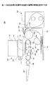
図2は第一の実施形態の画像形成装置の機構の概略を説明する図である。 FIG. 2 is a diagram for explaining the outline of the mechanism of the image forming apparatus according to the first embodiment.
本実施形態の画像形成装置100は、画像形成部110、給紙トレイ120、搬送機構130、排紙トレイ140を有する。画像形成部110は、画像形成装置100本体の内部に設けられており、給紙トレイ120は画像形成装置100本体の下方側に多数枚の記録媒体(以下「用紙」という。)20を積載可能に配置されている。排紙トレイ140は、画像形成装置100本体の側方に装着さている。
The
本実施形態の画像形成装置100は、給紙トレイ120から給紙される用紙20を取り込み、搬送機構130によって用紙20を搬送しながら画像形成部110によって所要の画像を記録した後、排紙トレイ140に用紙20を排紙する。
The
また本実施形態の画像形成装置100は、画像形成装置100本体に対して着脱可能に設けられた両面ユニット150を有する。本実施形態では、両面印刷を行うときには、一面(表面)印刷終了後、搬送機構130によって用紙20を逆方向に搬送しながら両面ユニット150内に取り込む。そして用紙20を反転させて他面(裏面)を印刷可能面とし、再度搬送機構130に送り込み、他面(裏面)印刷終了後排紙トレイ140に用紙20を排紙する。
Further, the
本実施形態の画像形成部110は、ガイドシャフト111、112にキャリッジ113を摺動可能に保持し、図示しない主走査モータでキャリッジ113を用紙20の搬送方向と直交する方向に移動(主走査)させる。キャリッジ113には、液滴を吐出する複数の吐出口であるノズル孔114n(図4参照)を配列した液滴吐出ヘッドで構成した記録ヘッド114を搭載し、また、この記録ヘッド114に液体を供給するインクカートリッジ115を着脱自在に搭載している。なお、インクカートリッジ115に代えてサブタンクを搭載し、メインタンクからインクをサブタンクに補充供給する構成とすることもできる。
The
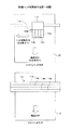
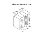
以下に図3を参照して本実施形態の記録ヘッド114について説明する。図3は記録ヘッドを説明する第一の図であり、図3(A)はシリアルヘッド方式を採用した場合の記録ヘッドを示し、図3(B)はラインヘッド方式を採用した場合の記録ヘッドを示している。図4は、記録ヘッドを説明する第二の図である。
Hereinafter, the
本実施形態の記録ヘッド114は、例えばイエロー(Y)、マゼンタ(M)、シアン(C)、ブラック(Bk)の各色のインク滴を吐出する液滴吐出ヘッドである独立した4個のインクジェットヘッド114y、114m、114c、114kとした。尚記録ヘッド114は、各色のインク滴を吐出する複数のノズル114nを有する1又は複数のヘッドを用いる構成とすることもできる。また色の数及び配列順序はこれに限るものではない。
The
記録ヘッド114を構成するインクジェットヘッドでは、圧電素子などの圧電アクチュエータや発熱抵抗体などの電熱変換素子を用いて液体の膜沸騰による相変化を利用するサーマルアクチュエータ、温度変化による金属相変化を用いる形状記憶合金アクチュエータ、静電力を用いる静電アクチュエータ等がインクを吐出するためのエネルギー発生手段として使用できる。
In the ink jet head constituting the
電熱変換素子には、低い電圧が加わっても抵抗値が変化しにくく、一定以上の電圧が加わった際に抵抗値が大きく変化する非線形な特性を有する電熱変換素子を用いることができる。線形な特性を有する電熱変換素子では、複数の発熱手段を選択的に駆動する際に、非選択の発熱手段にノイズ電圧が加わり、エネルギーを浪費したり、また駆動電圧に影響を与えてインクの吐出量が変化し、記録画像に影響を与えてしまう恐れがある。 As the electrothermal conversion element, it is possible to use an electrothermal conversion element having a non-linear characteristic in which the resistance value hardly changes even when a low voltage is applied and the resistance value greatly changes when a voltage of a certain level or more is applied. In an electrothermal conversion element having a linear characteristic, when a plurality of heat generating means are selectively driven, noise voltage is applied to the non-selected heat generating means, energy is wasted, and the drive voltage is affected to affect the ink. There is a possibility that the ejection amount changes and affects the recorded image.
特に、複数の縦配線と複数の横配線とに電圧を印加して、縦配線と横配線との交点にマトリクス状に配置された発熱手段を選択的に駆動するインクジェット記録ヘッドでは、駆動の過程で非選択の発熱手段に駆動電圧より低い電圧が印加される恐れがあり、この電圧が順方向である場合には、非選択の発熱手段に不要な発熱が生じることになる。不必要な発熱が生じて熱が蓄積されると、いざ吐出される際に加熱すると規定以上に発熱してしまい、その結果必要以上の量のインクが吐出されてしまう。そのため、ノズル毎のインク吐出量にばらつきが生じてしまう。 In particular, in an inkjet recording head that applies voltages to a plurality of vertical wirings and a plurality of horizontal wirings and selectively drives heating means arranged in a matrix at intersections of the vertical wirings and the horizontal wirings, the driving process In this case, a voltage lower than the driving voltage may be applied to the non-selected heat generating means. If this voltage is in the forward direction, unnecessary heat generation occurs in the non-selected heat generating means. If unnecessary heat is generated and heat is accumulated, if it is heated when it is ejected, it will generate more heat than specified, and as a result, an excessive amount of ink will be ejected. As a result, the ink discharge amount varies from nozzle to nozzle.
ところが、非線形な特性を有する電熱変換素子を用いれば、ノイズなどの駆動電圧よりも低い電圧が発熱手段に加わっても不要な発熱が生じないため、インクの吐出量のばらつきが抑制でき、印刷物の粒状性、階調性が良好となる。また、不必要な発熱を防ぐことができるため、エネルギーの浪費を防ぐことができる。 However, if an electrothermal conversion element having non-linear characteristics is used, even if a voltage lower than the driving voltage such as noise is applied to the heating means, unnecessary heat generation does not occur. Graininess and gradation are improved. Moreover, since unnecessary heat generation can be prevented, waste of energy can be prevented.
また、記録ヘッド114の各電熱変換素子の抵抗値を測定し、その抵抗値に基づいて各電熱変換素子に印加する駆動電圧を調整することができる。特に記録ヘッドが長尺化した場合には、ノズル毎の電熱変換素子の抵抗値にばらつきが生じやすくなり、その結果、吐出されるインク量にばらつきが生じてしまう。しかし、各電熱抵抗素子の抵抗値をフィードバックして印加電圧を調整することで、狙いの大きさのインク滴を吐出することができる。
Further, the resistance value of each electrothermal conversion element of the
さらに、サーマル方式の記録ヘッド114を用いる場合、電熱変換素子(吐出エネルギー発生体)に保護層を設けても良い。保護層を設けることで、インクによる浸食、コゲーション(インク成分の焦げ付き)やキャビテーション(気泡収縮時の衝撃による破壊)が直接電熱変換素子に作用しなくなる。電熱変換素子を痛めつけることがないので、電熱変換素子の寿命を長くすることができる。
Further, when the
図2に戻って、本実施形態の給紙トレイ120の用紙20は、給紙コロ(半月コロ)121と図示しない分離パッドによって1枚ずつ分離され装置内に給紙され、搬送機構130に送り込まれる。
Returning to FIG. 2, the
搬送機構130は、搬送ガイド部123、搬送ローラ124、加圧コロ125、ガイド部材126、127、押し付けコロ128を有する。搬送ガイド部123は、給紙された用紙20をガイド面123aに沿って上方にガイドし、また両面ユニット150から送り込まれる用紙20をガイド面123bに沿ってガイドする。搬送ローラ124は、用紙20を搬送する。加圧コロ125は、搬送ローラ124に対して用紙20を押し付ける。
The
ガイド部材126は用紙20を搬送ローラ124側にガイドし、ガイド部材127は両面印刷時に戻される用紙20を両面ユニット150に案内する。押し付けコロ128は、搬送ローラ24から送り出す用紙3を押圧する。
The
また本実施形態の搬送機構130は、記録ヘッド114で用紙20の平面性を維持したまま搬送するために、搬送ベルト133、帯電ローラ134、ガイドロール135を有する。搬送ベルト133は、駆動ローラ131と従動ローラ132との間に掛け渡しされている。帯電ローラ134は、搬送ベルト133を帯電させる。ガイドローラ135は帯電ローラ134に対向する位置にある。
Further, the
また本実施形態の搬送機構130は、図示していないが、搬送ベルト133を画像形成部110に対向する部分で案内するガイド部材(プラテンプレート)と、搬送ベルト133に付着した記録液(インク)を除去するためのクリーニング手段である多孔質体などからなるクリーニングローラなどを有している。
Although not shown, the
本実施形態の搬送ベルト133は、無端状ベルトであり、駆動ローラ131と従動ローラ132との間に掛け渡されて、図2の矢示方向(用紙搬送方向)に周回するように構成している。
The
本実施形態の搬送ベルト133は、単層構成、又は図5に示すように第1層(最表層)133aと第2層(裏層)133bの2層構成あるいは3層以上の構成とすることができる。図5は、搬送ベルトを説明する図である。例えば、搬送ベルト133は、抵抗制御を行っていない純粋な厚さ40μm程度の樹脂材、例えばETFEピュア材で形成した用紙吸着面となる表層と、この表層と同材質でカーボンによる抵抗制御を行った裏層(中抵抗層、アース層)とで構成する。
The
帯電ローラ134は、搬送ベルト133の表層に接触し、搬送ベルト133の回動に従動して回転するように配置されている。この帯電ローラ134には図示しない高圧回路(高圧電源)から高電圧が所定のパターンで印加される。搬送機構130から下流側には画像が記録された用紙30を排紙トレイ140に送り出すための排紙ローラ138を備えている。
The charging
本実施形態の画像形成装置100において、搬送ベルト133は矢示方向に周回し、高電位の印加電圧が印加される帯電ローラ134と接触することで正に帯電される。この場合、帯電ローラ134からは所定の時間間隔で極性を切り替えることによって、所定の帯電ピッチで帯電させる。
In the
ここで、この高電位に帯電した搬送ベルト133上に用紙20が給送されると、用紙20内部が分極状態になり、搬送ベルト133上の電荷と逆極性の電荷が用紙20の搬送ベルト133との接触面に誘電される。搬送ベルト133上の電荷と搬送される用紙20上に誘電された電荷同士が互いに静電的に引っ張り合い、用紙20は搬送ベルト133に静電的に吸着される。このようにして、搬送ベルト133に強力に吸着した用紙20は反りや凹凸が校正され、高度に平らな面が形成される。
Here, when the
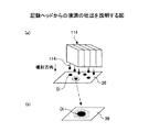
そこで、搬送ベルト133を周回させて用紙20を移動させ、キャリッジ113を片方向又は双方向に移動走査しながら画像信号に応じて記録ヘッド114を駆動する。そして、図6(a)、(b)に示すように、記録ヘッド114から液滴114iを吐出(噴射)させて、停止している用紙20に液滴であるインク滴を着弾させてドットDiを形成することにより、1行分を記録し、用紙20を所定量搬送後、次の行の記録を行う。図6は、記録ヘッドからの液滴の吐出を説明する図である。
Therefore, the
記録終了信号又は用紙20の後端が記録領域に到達した信号を受けることにより、記録動作を終了する。なお、図6(b)は図6(a)のドットDi形成部分を拡大したものである。
When the recording end signal or the signal that the rear end of the
このようにして、画像が記録された用紙20は排紙ローラ138によって排紙トレイ140に排紙される。
In this way, the
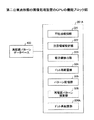
次に、図7を参照して本実施形態の画像形成装置100の機能構成について説明する。図7は、第一の実施形態の画像形成装置の機能構成を説明する図である。
Next, the functional configuration of the
本実施形態の画像形成装置100は、制御部200、不吐出検知センサ210、主走査モータ220、副走査モータ230、高圧回路240、操作パネル250、環境センサ260を有する。また本実施形態の画像形成装置100は、プリンタドライバ310を有するコンピュータ300と接続されており、コンピュータ300で作成された画像データを画像として形成する。
The
制御部200は、画像形成装置100の動作を制御する。不吐出検知センサ210は、キャリッジ113の有する記録ヘッド114において吐出不良のノズルを検知する。本実施形態の不吐出検出部210は、例えばヘッドの一端に発光素子、他端に受光素子を配置し、インク液滴の吐出時に発光素子から発光された光を受光素子が受光するか否かにより、吐出不良を検知しても良い。
The
主走査モータ220は、キャリッジ113を駆動させる。副走査モータ230は搬送ベルト133を駆動させる。高圧回路240は、帯電ローラ134を帯電させる。操作パネル250は、画像形成装置100を操作するためのパネルであり、表示機能を有していても良い。環境センサ260は、環境温度や環境湿度を検出するためのセンサである。
The
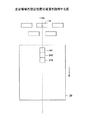
以下に本実施形態の制御部200について説明する。本実施形態の制御部200は、CPU(Central Processing Unit)201、ROM(Read Only Memory)202、RAM(Random Access Memory)203、NVRAM(Non Volatile RAM)204、ASIC(Application Specific Integrated Circuit)205、ホストI/F(Interface)206、I/O(Input/Output)207、ヘッド駆動制御部208、ヘッドドライバ209、主走査モータ駆動部211、副走査モータ制御部212を有する。
Below, the
CPU201は、装置全体の制御を司る。ROM202は、CPU201が実行するプログラム、その他の固定データが格納されている。RAM203は、画像データ等が一時的に格納される。NVRAM104は、画像形成装置100の電源が遮断されている間もデータを保持する不揮発性メモリである。ASIC205は、各種信号処理、並び替え等を行う画像処理やその他装置全体を制御するための入出力信号を処理する。ホストI/F205は、コンピュータ300とデータや信号の送受を行うためのインターフェイスである。I/O206は、環境センサ260や、図示しない各種センサからの検知信号が入力される。
The
ヘッド駆動制御部208及びヘッドドライバ209は、記録ヘッド114の駆動を制御する。主走査モータ駆動部211は、主走査モータ220を駆動する。副走査モータ駆動部212は、副走査モータ230を駆動する。
A head
本実施形態の制御部200は、データ処理装置、イメージスキャナなどの画像読み取り装置、デジタルカメラなどの撮像装置などにより実現されるコンピュータ300側からの画像データを含む印刷データ等をケーブル或いはネットを介してI/F106で受信する。尚制御部200に対する印刷データの生成出力は、コンピュータ300側のプリンタドライバ320により行われる。
The
本実施形態のCPU201は、I/F206に含まれる受信バッファ内の印刷データを読み出して解析し、ASIC205にてデータの並び替え処理等を行ってヘッド駆動制御部207に画像データを転送する。なお、画像出力するための印刷データのビットマップデータへの変換は、前述したようにコンピュータ300側のプリンタドライバ310で画像データをビットマップデータに展開して転送するようにしているが、例えばROM202にフォントデータを格納して行っても良い。
The
ヘッド駆動制御部207は、記録ヘッド114の1行分に相当する画像データ(ドットパターンデータ)を受け取ると、この1行分のドットパターンデータを、クロック信号に同期して、ヘッドドライバ208にシリアルデータで送出し、また所定のタイミングでラッチ信号をヘッドドライバ208に送出する。
When the head
本実施形態のヘッド駆動制御部207は、駆動波形(駆動信号)のパターンデータを格納したROM(ROM202で構成することもできる。)と、このROMから読出される駆動波形のデータをD/A変換するD/A変換器を含む波形生成回路及びアンプ等で構成される駆動波形発生回路を含む。
The head
本実施形態のヘッドドライバ208は、ヘッド駆動制御部207からの信号に基づき、所要の駆動波形を選択的に記録ヘッド14のアクチュエータに印加してヘッドを駆動する。
The
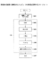
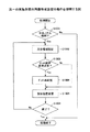
次に図8を参照して本実施形態のコンピュータ300について説明する。図8は、画像形成装置に接続されたコンピュータの処理を説明するフローチャートである。
Next, the
本実施形態のコンピュータ300は、画像データを画像形成装置100へ転送するプリンタドライバ310を有する。図8では、プリンタドライバ310の処理を説明する。
The
プリンタドライバ310は、アプリケーションソフトなどから画像データが与えられると(ステップS801)、をモニター表示用の色空間から画像処理装置用の色空間への変換(RGB表色系→CMY表色系)を行う(ステップS802)。続いてプリンタドライバ310は、CMY表色系の値から黒生成/下色除去(Black Generation/Under Color Removal)を行う(ステップS803)。
When the image data is given from application software or the like (step S801), the
続いてプリンタドライバ310は、画像形成装置の特性やユーザの嗜好を反映した入出力補整であるγ補整を行い(ステップS804)、画像形成装置100の解像度に合わせて拡大処理(ステップS805)を行う。そしてプリンタドライバ310は、画像データを画像形成装置から噴射するドットのパターン配置に置き換える多値・少値マトリクスを含む中間調処理を行い(ステップS806)、画像データを画像形成装置100へ出力する(ステップS807)。
Subsequently, the
本実施形態の画像形成装置100では、このようにしてプリンタドライバから転送された画像データに基づき画像形成する際に、記録ヘッド114のノズルに吐出不良のノズルがあるか否かを検知する。そして吐出不良のノズルが存在する場合、本実施形態の画像形成装置100は、ノズル欠損を補うように補整を行う。本実施形態の画像形成装置100では、この補整の仕方に特徴があるため、以下に本実施形態の画像形成装置100における画像の補整について説明する。
In the
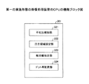
図9は、第一の実施形態の画像処理装置のCPUの機能ブロック図である。本実施形態の画像形成装置100では、CPU201は、不吐出検知センサ210の信号から不吐出ノズルの有無を検知し、不吐出ノズルが検知された場合は画像を補整する。
FIG. 9 is a functional block diagram of the CPU of the image processing apparatus according to the first embodiment. In the
CPU201は、不吐出検知部321、注目領域設定部322、結合線抽出部323、ドット再配置部324を有する。
The
CPU201は、不吐出検知部321により不吐出のノズル(以下、不良ノズル)を検知すると、注目領域設定部322により不良ノズルにより吐出される液滴により形成されるドット(以下、形成予定ドットと言う。)を中心とした所定領域を注目領域として設定する。そして結合線抽出部323により、注目領域内に配置される予定のドットの重心を結んだ線(以下、結合線)を抽出し、ドット再配置部324により注目領域内で結合線の傾きとドットのサイズを示す値の合計が変わらないようにドットの再配置を行う。尚注目領域内に配置される予定のドットには、形成予定ドットも含まれる。
When the
以下にCPU201の有する各部についてさらに説明する。本実施形態の不吐出検知部321は、不吐出検知センサ210から出力される信号に基づき、不良ノズルが存在するか否かを判断する。本実施形態の不吐出検知部321は、不良ノズルの存在を検知すると、不良ノズルがあることを示すフラグをたて、フラグに基づき不良ノズルの位置を把握する。
Below, each part which CPU201 has is further explained. The
本実施形態の注目領域設定部322は、画像において形成予定ドットの位置を中心に所定範囲の領域を注目領域として設定する。本実施形態では、例えば形成予定ドットの位置を中心とした3ドット×3ドットの領域を注目領域として設定する。尚注目領域に設定する範囲は、予め画像形成装置100に設定されていても良く、この範囲は変更可能であっても良い。
The attention
結合線抽出部323は、コンピュータ300から渡された画像データに基づき画像を形成した場合に、注目領域内に配置されるドットの重心を結ぶ線である結合線を抽出する。
When an image is formed based on the image data delivered from the
ドット再配置部324は、結合線の傾き及び注目領域内のドットサイズを示す値に基づき、注目領域内のドットの再配置を行う。本実施形態のドット再配置部324は、画像データに基づき画像を形成した際に注目領域内に形成される線画の傾きを維持しつつ、ドットのサイズや位置を変更することでドットの再配置を行う。
The
具体的にはドット再配置部324は、結合線の傾きを維持しながら、注目領域内のドットサイズを示す値の合計が、再配置前と再配置後と同じになるようにドットの再配置を行う。ドット再配置部324の処理の詳細は後述する。
Specifically, the
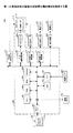
次に図10を参照して本実施形態の画像形成装置100の動作を説明する。図10は、第一の実施形態の画像形成装置の動作を説明する図である。
Next, the operation of the
本実施形態の画像形成装置100において画像形成処理が開始されると、CPU201は不吐出検知部321により不良ノズルの検知を行う(ステップS1001)。本実施形態の不吐出検知部321では、画像データによる画像形成を行う前に、ノズルからインク液滴を吐出させ、不良ノズルが存在するか否かを検知しても良い。
When the image forming process is started in the
ステップS1001において不良ノズルが検知されると、CPU201は注目領域設定部322により注目領域を設定する(ステップS1002)。ステップS1002において注目領域が設定されると、注目領域内でドットの再配置が必要か否かを判断する(ステップS1003)。CPU201は、例えばステップS1001で検知した不良ノズルによる形成予定ドットが注目領域内に存在すれば、ドットの再配置が必要と判断する。CPU201は、ドットの再配置を行うことで、不良ノズルによる画像の欠損を補整する。またCPU201は、例えば注目領域内に形成予定ドットが存在しない場合には、ドットの再配置は不要と判断する。
When a defective nozzle is detected in step S1001, the
ステップS1003においてドットの再配置が必要と判断されると、CPU201は、ドットの再配置を行う(ステップS1004)。
If it is determined in step S1003 that dot rearrangement is necessary, the
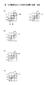
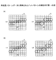
以下に図11、図12を参照してステップS1002からステップS1004の処理の詳細を説明する。図11は、第一の実施形態のドット再配置を説明する第一の図であり、図12は、第一の実施形態のドット再配置を説明する第二の図である。 Details of the processing from step S1002 to step S1004 will be described below with reference to FIGS. FIG. 11 is a first diagram illustrating dot rearrangement according to the first embodiment, and FIG. 12 is a second diagram illustrating dot rearrangement according to the first embodiment.
図11は、結合線の傾きが45度の線を補整する場合を示す。図11(A)は、入力された画像データにより形成される線画を示しており、図11(B)は本実施形態の補整を適用した例を示しており、図11(C)、(D)は本実施形態の補整が適用されなかった場合を示している。 FIG. 11 shows a case in which a line having a combined line inclination of 45 degrees is compensated. FIG. 11A shows a line drawing formed from input image data, and FIG. 11B shows an example in which the correction of the present embodiment is applied, and FIGS. ) Shows a case where the correction of this embodiment is not applied.
図11(A)において、不良ノズルが存在しない場合は領域S1に示すようにドットD1、D2、D3が形成される。この場合、領域S1におけるドットD1、D2、D3の重心を結んだ結合線は、結合線H1とである。またドットD1、D2、D3を形成するインク液滴の大きさのサイズは中滴とし、この中滴を示す値を2とすると、領域S1におけるドットD1、D2、D3を形成する液滴のサイズの合計の値は6となる。 In FIG. 11A, when there is no defective nozzle, dots D1, D2, and D3 are formed as shown in region S1. In this case, a connecting line connecting the centers of gravity of the dots D1, D2, and D3 in the region S1 is a connecting line H1. The size of the ink droplets forming the dots D1, D2, and D3 is a medium droplet. If the value indicating the medium droplet is 2, the size of the droplets forming the dots D1, D2, and D3 in the region S1. The total value of is 6.
ここで液滴のサイズを示す値について説明する。インク液滴を吐出させて画像形成を行う画像形成装置では、通常はインク液滴の大きさを調整して複数サイズの大きさのドットを形成することができる。インク液滴のサイズは、例えば大滴、中滴、小滴等があり、大滴により形成されるドットは大きく、小敵により形成されるドットは小さくなる。本実施形態の画像形成装置100では、ドットサイズと、ドットサイズと対応した数値とが予め設定されており、ドットサイズをドットサイズに対応した数値で表現するものとした。
Here, a value indicating the droplet size will be described. In an image forming apparatus that forms an image by ejecting ink droplets, it is usually possible to adjust the size of ink droplets to form dots of a plurality of sizes. The ink droplet size includes, for example, a large droplet, a medium droplet, and a small droplet. The dot formed by the large droplet is large and the dot formed by the small enemy is small. In the
本実施形態では、例えば小滴により形成されたドットサイズを示す値を1、中滴により形成されたドットサイズを示す値を2、大滴により形成されたドットサイズを示す値を3とした。よって図11(A)から、ドットD1、D2、D3は中滴により形成されたドットであることがわかる。尚本実施形態ではドットサイズを示す値として、インク液滴の量を用いても良い。 In this embodiment, for example, a value indicating the dot size formed by a small droplet is 1, a value indicating a dot size formed by a medium droplet is 2, and a value indicating a dot size formed by a large droplet is 3. Therefore, it can be seen from FIG. 11A that the dots D1, D2, and D3 are dots formed by medium drops. In this embodiment, the amount of ink droplets may be used as a value indicating the dot size.
次に図11(B)〜(D)を参照して、領域S1においてラインL1、L2、L3のうちラインL2にドットを形成するノズルが不良ノズルであった場合の補整について説明する。図11(A)に示す線画では、ドットD2が形成予定ドットとなる。 Next, with reference to FIGS. 11B to 11D, correction when the nozzle that forms dots in the line L2 among the lines L1, L2, and L3 in the region S1 is a defective nozzle will be described. In the line drawing shown in FIG. 11A, the dot D2 is a dot to be formed.
図11(B)は本実施形態による補整を適用した場合のドット再配置後の領域S1を示している。本実施形態のドット再配置部324は、画像データを解析して再配置前の領域S1におけるドットの配置を把握し、結合線Hの傾きを取得する。結合線Hの傾きとは、すなわち領域S1内に画像データにより表現される線画の傾きである。
FIG. 11B shows a region S1 after dot rearrangement when the correction according to the present embodiment is applied. The
本実施形態のドット再配置部324は、ドット再配置後の結合線Hの傾きを維持するようにドットを再配置する。また本実施形態のドット再配置部324では、領域S1におけるドットサイズを示す値の合計が、再配置前と同じ値になるようにドットを再配置する。
The
例えばラインL2を形成するノズルが不良ノズルであった場合、この不良ノズルによる形成予定ドットを中心として注目領域を設定する。本実施形態では、注目領域は3ドット×3ドットの範囲とし、領域S1が注目領域である。注目領域が設定されると、ドット再配置部324は、領域S1からドットD1、D2、D3の重心を結んだ結合線Hを抽出し、結合線Hの傾きを変えないようにドットD1とドットD3のサイズを変える。このときドット再配置部324は、ドットD1のドットサイズを示す値と、ドットD3のドットサイズを示す値との合計値が、画像データにより画像形成した場合と変わらないようにする。
For example, when the nozzle that forms the line L2 is a defective nozzle, a region of interest is set centering on a dot to be formed by the defective nozzle. In this embodiment, the attention area is a range of 3 dots × 3 dots, and the area S1 is the attention area. When the attention area is set, the
図11(B)では、ドットD1とドットD3のドットサイズを3とすれば、領域S1におけるドットサイズを示す値の合計値は6となり、補整前の値と等しくなる。またドットD1とドットD3の重心を結んだ結合線H1の傾きは、結合線Hと等しくなる。このように補整すれば、線画の太さを変えずに、且つ線画が途切れないように不良ノズルによる画像の欠損を補うことができる。 In FIG. 11B, if the dot sizes of the dots D1 and D3 are 3, the total value of the dot sizes in the region S1 is 6, which is equal to the value before correction. Further, the inclination of the connecting line H1 connecting the centers of gravity of the dots D1 and D3 is equal to the connecting line H. By correcting in this way, it is possible to compensate for image loss due to defective nozzles without changing the thickness of the line drawing and without interrupting the line drawing.
図11(C)の例では、ラインL1、L3にドット数を増やす補整を行っているが、結合線H2の角度は結合線Hと等しくならない。このため線画にがたつきが生じる虞がある。 In the example of FIG. 11C, correction is performed to increase the number of dots in the lines L <b> 1 and L <b> 3, but the angle of the coupling line H <b> 2 is not equal to the coupling line H. For this reason, there is a possibility that the line drawing may be rattled.
図11(D)では、結合線H3の角度は結合線Hと等しくなるが、ドットサイズを示す値の合計値が4となり、図11(A)に示す6と等しくならない。この場合、インクの付着量が少ないために線が細くなって途切れる虞がある。 In FIG. 11D, the angle of the combined line H3 is equal to the combined line H, but the total value of the values indicating the dot size is 4, which is not equal to 6 shown in FIG. In this case, since the amount of ink attached is small, there is a possibility that the line becomes thin and breaks.
図12は、結合線の傾きが0度の横線を補整する場合を示す。図12(A)は、入力された画像データにより形成される線画を示しており、図12(B)は本実施形態の補整を適用した例を示しており、図12(C)は本実施形態の補整が適用されなかった場合を示している。 FIG. 12 shows a case where a horizontal line with a slope of 0 degrees is corrected. FIG. 12A shows a line drawing formed from input image data, FIG. 12B shows an example in which the correction of this embodiment is applied, and FIG. 12C shows this embodiment. It shows the case where shape correction is not applied.
図12(B)では、結合線H12が図12(A)の結合線H11と同じ傾きであり、かつドットサイズを示す値の合計値も図12(A)に示す値と等しくなる。図12(B)では、線が1ラインシフトするだけで、線画の太さを変えずに、且つ線画が途切れないように不良ノズルによる画像の欠損を補うことができる。 In FIG. 12B, the combined line H12 has the same inclination as the combined line H11 in FIG. 12A, and the total value indicating the dot size is also equal to the value illustrated in FIG. In FIG. 12B, it is possible to compensate for image loss due to a defective nozzle so that the line drawing does not change and the line drawing is not interrupted by shifting the line by one line.
図12(C)では、ラインL1、L3からドットを吐出させているため、結合線H13が2本となり、結合線11と一致しない。図12(C)では、線が2本となり、線の形状を変えずに補整することができない。 In FIG. 12C, since the dots are ejected from the lines L1 and L3, there are two coupled lines H13, which do not coincide with the coupled line 11. In FIG. 12C, the number of lines is two and cannot be corrected without changing the shape of the lines.
図13は、第一の実施形態により再配置されたドットの例を示す図である。図13(A)は、図11(B)に示す補整を行った場合を示しており、図13(B)は図12(B)に示す補整を行った結果を示している。 FIG. 13 is a diagram illustrating an example of dots rearranged according to the first embodiment. FIG. 13 (A) shows the case where the correction shown in FIG. 11 (B) is performed, and FIG. 13 (B) shows the result of the correction shown in FIG. 12 (B).
続いてCPU201は、画像における注目領域の設定位置を変更する(ステップS1005)。以下に図14を参照して注目領域の設定位置の変更について説明する。図14は、注目領域の設定位置の変更を説明する図である。
Subsequently, the
例えば記録ヘッド114の有するノズル孔114nが不良ノズルであり、用紙20が矢印方向に搬送されて画像が形成される場合、ノズル孔114nにより形成されるべき形成予定ドットが欠損する。そこで本実施形態の注目領域設定部322は、形成予定ドットを含むラインL4を辿るように、注目領域を設定していく。
For example, when the
本実施形態の画像形成装置100は、例えばラインL4を中心とした領域S41を注目領域に設定し、ステップS1003からステップS1005までの処理を行う。次に画像形成装置100は、領域S41に隣接し且つラインL4を中心とする領域S42を注目領域に設定して同様の処理を行う。領域S43に対しても同様である。
For example, the
CPU201は、形成予定ドットが含まれる全ての範囲について、ステップS1002からステップS1005までの処理を実行したか否かを確認する(ステップS1006)。図14の例では、ラインL4の始点から終点までを含む範囲について、ステップS1002からステップS1005までの処理を実行したか否かを確認する。
The
ステップS1006において、全ての範囲について処理を行った場合には処理を終了する。ステップS1006において全ての範囲について処理を行っていない場合は、ステップS1002以降の処理を繰り返す。 In step S1006, when the process has been performed for all ranges, the process ends. If the process has not been performed for all ranges in step S1006, the processes in and after step S1002 are repeated.
本実施形態の画像形成装置100では、以上のようにしてコンピュータ300から入力された画像データのドットパターンの再配置を行う。そして画像形成装置100は、再配置後のドットパターンにしたがって画像形成を行うことで、不良ノズルの存在による画像の欠損やスジ等を低減させることができる。
In the
したがって本実施形態では、不良ノズルによる画像の欠損を補整することで、線画の形状を崩さずに不良ノズルによるスジを低減させることができる。 Therefore, in the present embodiment, by correcting the defect of the image due to the defective nozzle, it is possible to reduce streaks due to the defective nozzle without destroying the shape of the line drawing.
(第二の実施形態)
以下に図面を参照して本発明の第二の実施形態について説明する。本発明の第二の実施形態では、不良ノズルの位置と画像データによるドットパターンと対応した再配置後のパターンが記憶装置に予め格納されている点のみ第一の実施形態と相違する。したがって以下の第二の実施形態の説明では、第一の実施形態との相違点についてのみ説明し、第一の実施形態と同様の機能構成を有するものには第一の実施形態の説明で用いた符号と同様の符号を付与し、その説明を省略する。
(Second embodiment)
A second embodiment of the present invention will be described below with reference to the drawings. The second embodiment of the present invention is different from the first embodiment only in that the rearranged pattern corresponding to the position of the defective nozzle and the dot pattern based on the image data is stored in advance in the storage device. Therefore, in the following description of the second embodiment, only differences from the first embodiment will be described, and those having the same functional configuration as the first embodiment will be used in the description of the first embodiment. The same reference numerals as those used are assigned, and the description thereof is omitted.
図15は、第二の実施形態の画像処理装置のCPUの機能ブロック図である。本実施形態のCPU201Aは、第一の実施形態のCPU201の有する各部に加え、ドット再配置部324A、パターン記憶部325、再配置パターン検索部326を有する。本実施形態のCPU201Aは、再配置パターンデータベース400が格納された記憶装置と接続されており、この再配置パターンデータベース400内に格納された再配置パターンに基づきドットの再配置を行う。
FIG. 15 is a functional block diagram of the CPU of the image processing apparatus according to the second embodiment. The CPU 201A of this embodiment includes a
以下に本実施形態の再配置パターンデータベース400について説明する。本実施形態では、再配置パターンデータベース400は、制御部200の有する記憶装置であるROM202やNVRAM204等に格納されている。再配置パターンデータベース400では、注目領域における形成予定ドットの位置と、注目領域内のドットの再配置を行う前のドットパターンと、再配置後のドットパターンとが対応付けられて記憶されている。注目領域内のドットの再配置を行う前のドットパターンとは、入力された画像データで表現されるドットパターンである。
The
具体的には、再配置パターンデータベース400には、例えば図11(A)で示す注目領域S1における形成予定ドットを含むラインL2と、画像データで表現されるドットパターンと、図11(B)で示す補整後のドットパターンと、が対応付けられている。また再配置パターンデータベース400には、図12(A)に示す注目領域S2における形成予定ドットを含むラインと、画像データにより表現されるドットパターンと、図12(B)に示す補整後のドットパターンとが対応付けられている。
Specifically, in the
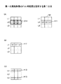
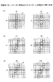
再配置パターンデータベース400は、上述したパターン以外にも、様々なドットパターンが格納されている。図16、図17を参照して再配置パターンデータ400格納されているドットパターンの例についてさらに説明する。図16は再配置パターンデータに格納されたドットパターンの例を示す第一の図であり、図17は再配置パターンデータに格納されたドットパターンの例を示す第二の図である。尚図16、図17に示す補整後のパターンは、第一の実施形態で説明した補整の処理により生成されたパターンであることが好ましい。
The
図16、図17では、8ドット×9ドットの領域を注目領域として設定することを前提としている。図16(A)では、注目領域Sにおける形成予定ドットの位置はラインL6を形成する位置であり、補整前のドットパターンがパターンP1であり、補整後のドットパターンがパターンP2である。再配置パターンデータベース400では、この3つの情報が対応付けられている。図16(B)では、注目領域Sにおける不良ノズルの位置がラインL6であり、補整前のドットパターンがパターンP3であり、補整後のドットパターンがパターンP4である。
16 and 17, it is assumed that an area of 8 dots × 9 dots is set as the attention area. In FIG. 16A, the position of the dot to be formed in the attention area S is the position where the line L6 is formed, the dot pattern before correction is the pattern P1, and the dot pattern after correction is the pattern P2. In the
図17(A)では、注目領域Sにおける形成予定ドットの位置はラインL6を形成する位置であり、補整前のドットパターンがパターンP5であり、補整後のドットパターンがパターンP6である。図17(B)では、注目領域Sにおける形成予定ドットの位置はラインL6を形成する位置であり、補整前のドットパターンがパターンP7であり、補整後のドットパターンがパターンP8である。図17(C)では、注目領域Sにおける形成予定ドットの位置はラインL6を形成する位置であり、補整前のドットパターンがパターンP9であり、補整後のドットパターンがパターンP10である。 In FIG. 17A, the position of the dot to be formed in the attention area S is the position where the line L6 is formed, the dot pattern before correction is the pattern P5, and the dot pattern after correction is the pattern P6. In FIG. 17B, the position of the dot to be formed in the attention area S is the position where the line L6 is formed, the dot pattern before correction is the pattern P7, and the dot pattern after correction is the pattern P8. In FIG. 17C, the position of the dot to be formed in the attention area S is the position where the line L6 is formed, the dot pattern before correction is the pattern P9, and the dot pattern after correction is the pattern P10.
図15に戻って、本実施形態のパターン記憶部325は、ドット再配置部324により再配置されたドットのパターンと、再配置前の入力された画像データに基づくドットのパターンと、注目領域における不良ノズルの位置とを対応付けて再配置パターンデータベース400に記憶させる。
Returning to FIG. 15, the
本実施形態の再配置パターン検索部326は、再配置パターンデータベース400から再配置後のドットパターンを検索する。本実施形態の再配置パターン検索部326は、不吐出検知部321により検知された形成予定ドットの位置と、注目領域内の画像データによるパターンとに基づき再配置パターンデータベース400を検索し、対応するドットパターンを抽出する。
The rearrangement
本実施形態のドット再配置部324Aは、再配置パターン検索部326により抽出されたドットパターンとなるようにドットパターンを再配置する。
The
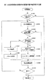
図18は、第二の実施形態の画像形成装置の動作を説明する図である。図18のステップS1801からステップS1803までの処理は、図10のステップS1001からステップS1003までの処理と同様であるから説明を省略する。 FIG. 18 is a diagram illustrating the operation of the image forming apparatus according to the second embodiment. The processing from step S1801 to step S1803 in FIG. 18 is the same as the processing from step S1001 to step S1003 in FIG.
ステップS1803においてドットの配置の変更が必要と判断された場合、CPU201Aは、再配置パターン検索部326により再配置パターンデータベース400の検索を行う(ステップS1804)。再配置パターン検索部326は、ステップS1801で検知された形成予定ドットの位置を取得する。また再配置パターン検索部326は、ステップS1802で設定された注目領域内の画像データを解析と、注目領域内で画像データにより表現されるドットパターンを取得する。そして再配置パターン検索部326は、取得した形成予定ドットの位置と、画像データにより表現されるドットパターンとを検索キーとして再配置パターンデータベース400を検索する。
When it is determined in step S1803 that the dot arrangement needs to be changed, the CPU 201A searches the
ステップS1804において、再配置パターンデータベース400に検索キーと一致するデータが存在する場合、再配置パターン検索部326は、検索キーと対応したドットパターンを再配置後のドットパターンとして読み出す(ステップS1805)。そしてCPU201Aは、読み出したドットパターンに基づきドット再配置部324Aによりドットの再配置を行い、ステップS1809へ進む(ステップS1806)。
In step S1804, if there is data that matches the search key in the
ステップS1804において、再配置パターンデータベース400に該当するデータが存在しない場合、ドット再配置部324は、結合線抽出部323により注目領域にあるドットの重心の結合線を抽出してドットの再配置を行う(ステップS1807)。ステップS1807の処理は、図10のステップS1004の処理と同様である。
In step S1804, when there is no corresponding data in the
ステップS1807において上述したようにドットの再配置を行うと、CPU201Aは、パターン記憶部325により再配置後のドットパターンと、不良ノズルの位置と、画像データによる再配置前のドットパターンとを対応付けて再配置パターンデータベース400に記憶させる(ステップS1808)。本実施形態では、このように再配置後のドットパターンを再配置パターンデータベース400に記憶させることで、不良ノズルの位置と画像データによるドットのパターンが同一である場合に、ステップS1807の処理を省き、記憶された再配置後のパターンを読み出すだけで補整を行うことができる。
When the dot rearrangement is performed as described above in step S1807, the CPU 201A associates the dot pattern after the rearrangement with the
ステップS1809とステップS1810の処理は、図10のステップS1005とステップS1006と同様であるから説明を省略する。 The processing in steps S1809 and S1810 is the same as that in steps S1005 and S1006 in FIG.
以上に説明したように、本実施形態では、予め再配置後のドットパターンを格納したデータベースを保持することにより、画像形成時の補整に係る処理の負担を軽減することができる。尚本実施形態では、再配置パターンデータベース400は画像形成装置内の記憶装置が有するものとして説明したが、これに限定されない。本実施形態の再配置パターンデータベース400は、例えばコンピュータ300側で有していても良い。この場合、CPU201Aは、ステップS1803までの処理を実行した後に、ドットパターンの検索をコンピュータ300側へ依頼し、検索結果のドットパターンをコンピュータ300から受け取っても良い。さらに、コンピュータ300において検索結果に基づくドットの再配置まで行っても良い。この場合再配置後のドットパターンが画像形成装置100へ渡される。
As described above, in the present embodiment, it is possible to reduce the burden of processing related to correction at the time of image formation by holding a database that stores dot patterns after rearrangement in advance. In the present embodiment, the
また本実施形態では、再配置パターンデータベース400に該当するデータが存在する場合は再配置後のドットパターンを生成するものとしたが、再配置パターンデータベース400に該当するデータが存在しない場合は、処理を終了してもよい。
In this embodiment, the dot pattern after the rearrangement is generated when the data corresponding to the
以上、各実施形態に基づき本発明の説明を行ってきたが、上記実施形態に示した要件に本発明が限定されるものではない。これらの点に関しては、本発明の主旨をそこなわない範囲で変更することができ、その応用形態に応じて適切に定めることができる。 As mentioned above, although this invention has been demonstrated based on each embodiment, this invention is not limited to the requirements shown in the said embodiment. With respect to these points, the gist of the present invention can be changed without departing from the scope of the present invention, and can be appropriately determined according to the application form.
Claims (10)
吐出不良の前記ノズルの検知する検知手段と、
前記吐出不良の前記ノズルにより形成されるべき形成予定ドットの位置を含む注目領域を設定する注目領域設定手段と、
前記吐出不良の前記ノズルが検知されたとき、前記注目領域内に前記画像データにより表現される線画の傾きと、前記注目領域内にあるドットのサイズを示す値とに基づき前記注目領域におけるドットの再配置を行う再配置手段と、を有する画像形成装置。 An image forming apparatus having a recording head that forms dots on a recording medium by ejecting ink droplets from a plurality of nozzles based on input image data,
Detection means for detecting the nozzles with poor discharge;
A region of interest setting means for setting a region of interest including the position of a dot to be formed to be formed by the nozzle having the ejection failure;
When the ejection failure nozzle is detected, the dot in the region of interest is based on the slope of the line drawing represented by the image data in the region of interest and the value indicating the size of the dot in the region of interest. An image forming apparatus having rearrangement means for performing rearrangement.
前記再配置手段は、
前記前記結合線の傾きを維持し、且つ前記注目領域内に形成される各ドットのサイズを示す値の合計値が前記注目領域内で画像データにより表現される線画と同じになるように前記ドットの再配置を行う請求項1記載の画像形成装置。 A connecting line extracting means for extracting a connecting line connecting the centroids of dots forming a line drawing represented by the image data in the region of interest;
The relocation means includes
The dot is maintained so that the inclination of the combined line is maintained, and the total value of the values indicating the size of each dot formed in the attention area is the same as the line drawing expressed by the image data in the attention area. The image forming apparatus according to claim 1, wherein the rearrangement is performed.
前記ドットを形成する前記インク液滴の大きさと対応付けられた値であり、予め設定された値である請求項1又は2記載の画像形成装置。 The value indicating the size of the dot is
The image forming apparatus according to claim 1, wherein the image forming apparatus is a value associated with a size of the ink droplet that forms the dot, and is a preset value.
前記形成予定ドットを中心とした所定範囲を前記注目領域として設定する請求項1ないし4の何れか一項に記載の画像形成装置。 The attention area setting means includes:
5. The image forming apparatus according to claim 1, wherein a predetermined range centering on the dot to be formed is set as the attention area.
前記注目領域における形成予定ドットの位置と、前記画像データにより表現される線画を形成するドットのパターンと、を検索キーとして前記パターン記憶装置を検索するパターン検索手段を有し、
前記再配置手段は、
前記パターン検索手段により前記検索キーに対応したドットのパターンが存在する場合に、前記パターン記憶装置から前記ドットのパターンを読み出して、読み出した前記ドットのパターンに基づきドットの再配置を行う請求項6記載の画像形成装置。 When the ejection failure is detected by the detection means,
Pattern search means for searching the pattern storage device using a position of a dot to be formed in the region of interest and a dot pattern forming a line drawing expressed by the image data as a search key;
The relocation means includes
The dot pattern corresponding to the search key is read by the pattern search unit, and the dot pattern is read from the pattern storage device, and the dots are rearranged based on the read dot pattern. The image forming apparatus described.
吐出不良の前記ノズルの検知する検知手順と、
前記吐出不良の前記ノズルにより形成されるべき形成予定ドットの位置を含む注目領域を設定する注目領域設定手順と、
前記吐出不良の前記ノズルが検知されたとき、前記注目領域内に前記画像データにより表現される線画の傾きと、前記注目領域内にあるドットのサイズを示す値とに基づき前記注目領域におけるドットの再配置を行う再配置手順と、を有する画像形成方法。 An image forming method using an image forming apparatus having a recording head that discharges ink droplets from a plurality of nozzles based on input image data to form dots on a recording medium,
A detection procedure for detecting the nozzle of defective discharge;
A region-of-interest setting procedure for setting a region of interest including the position of a formation-scheduled dot to be formed by the defective nozzle.
When the ejection failure nozzle is detected, the dot in the region of interest is based on the slope of the line drawing represented by the image data in the region of interest and the value indicating the size of the dot in the region of interest. A rearrangement procedure for performing rearrangement.
吐出不良の前記ノズルの検知する検知手順と、
前記吐出不良の前記ノズルにより形成されるべき形成予定ドットの位置を含む注目領域を設定する注目領域設定手順と、
前記吐出不良の前記ノズルが検知されたとき、前記注目領域内に入力された画像データにより表現される線画の傾きと、前記注目領域内にあるドットのサイズを示す値とに基づき前記注目領域におけるドットの再配置を行う再配置手順と、
前記形成予定ドットの位置と、前記画像データにより表現される線画を形成するドットのパターンと、再配置されたドットのパターンと、を対応付けてパターン記憶装置へ記録させるパターン記憶手順と、を有するパターン生成方法。 A pattern generation method for generating a dot pattern for forming an image by ejecting ink droplets from a recording head having a plurality of nozzles,
A detection procedure for detecting the nozzle of defective discharge;
A region-of-interest setting procedure for setting a region of interest including the position of a formation-scheduled dot to be formed by the defective nozzle.
When the ejection failure nozzle is detected, based on the inclination of the line drawing represented by the image data input in the region of interest and the value indicating the size of the dots in the region of interest A rearrangement procedure for rearranging dots;
A pattern storage procedure for associating the positions of the dots to be formed, the pattern of the dots forming the line drawing represented by the image data, and the pattern of the rearranged dots, and recording them in the pattern storage device Pattern generation method.
前記画像形成装置に、
吐出不良の前記ノズルの検知する検知ステップと、
前記吐出不良の前記ノズルにより形成されるべき形成予定ドットの位置を含む注目領域を設定する注目領域設定ステップと、
前記吐出不良の前記ノズルが検知されたとき、前記注目領域内に前記画像データにより表現される線画の傾きと、前記注目領域内にあるドットのサイズを示す値とに基づき前記注目領域におけるドットの再配置を行う再配置ステップと、を実行させる画像形成プログラム。 An image forming program that is executed in an image forming apparatus having a recording head that discharges ink droplets from a plurality of nozzles based on input image data to form dots on a recording medium,
In the image forming apparatus,
A detection step of detecting the nozzle having a discharge failure;
An attention area setting step for setting an attention area including a position of a formation planned dot to be formed by the nozzle having the ejection failure;
When the ejection failure nozzle is detected, the dot in the region of interest is based on the slope of the line drawing represented by the image data in the region of interest and the value indicating the size of the dot in the region of interest. A rearrangement step for performing rearrangement;
Priority Applications (2)
| Application Number | Priority Date | Filing Date | Title |
|---|---|---|---|
| JP2010206606A JP2012061663A (en) | 2010-09-15 | 2010-09-15 | Image forming apparatus, image forming method, pattern generating method, and image forming program |
| US13/137,742 US8628165B2 (en) | 2010-09-15 | 2011-09-09 | Image forming apparatus, image forming method, pattern forming method and recording medium |
Applications Claiming Priority (1)
| Application Number | Priority Date | Filing Date | Title |
|---|---|---|---|
| JP2010206606A JP2012061663A (en) | 2010-09-15 | 2010-09-15 | Image forming apparatus, image forming method, pattern generating method, and image forming program |
Publications (1)
| Publication Number | Publication Date |
|---|---|
| JP2012061663A true JP2012061663A (en) | 2012-03-29 |
Family
ID=45806290
Family Applications (1)
| Application Number | Title | Priority Date | Filing Date |
|---|---|---|---|
| JP2010206606A Pending JP2012061663A (en) | 2010-09-15 | 2010-09-15 | Image forming apparatus, image forming method, pattern generating method, and image forming program |
Country Status (2)
| Country | Link |
|---|---|
| US (1) | US8628165B2 (en) |
| JP (1) | JP2012061663A (en) |
Cited By (6)
| Publication number | Priority date | Publication date | Assignee | Title |
|---|---|---|---|---|
| JP2015136882A (en) * | 2014-01-23 | 2015-07-30 | セイコーエプソン株式会社 | Print control apparatus, print control method, and print control program |
| JP2015150751A (en) * | 2014-02-13 | 2015-08-24 | セイコーエプソン株式会社 | Image formation device and dot pattern determination method |
| JP2016155267A (en) * | 2015-02-24 | 2016-09-01 | 理想科学工業株式会社 | Inkjet printing device |
| JP2017013328A (en) * | 2015-06-30 | 2017-01-19 | 株式会社リコー | Ink jet recording apparatus, control method for ink jet recording apparatus, and control program for ink jet recording apparatus |
| JP2021084297A (en) * | 2019-11-27 | 2021-06-03 | キヤノン株式会社 | Image processing device, image processing method and program |
| JP2021160200A (en) * | 2020-03-31 | 2021-10-11 | キヤノン株式会社 | Image processing device, its control method and program |
Families Citing this family (6)
| Publication number | Priority date | Publication date | Assignee | Title |
|---|---|---|---|---|
| JP5442783B2 (en) * | 2012-02-02 | 2014-03-12 | 富士フイルム株式会社 | Image recording apparatus, image processing apparatus, image recording method, image processing method, and program |
| JP5676535B2 (en) * | 2012-08-28 | 2015-02-25 | 富士フイルム株式会社 | Image forming apparatus and image forming method |
| US10150286B2 (en) | 2015-12-08 | 2018-12-11 | Ricoh Company, Ltd. | Liquid discharging unit and liquid discharging device |
| US10384444B2 (en) * | 2017-04-28 | 2019-08-20 | Canon Kabushiki Kaisha | Recording apparatus and recording method |
| US10889127B2 (en) | 2018-03-19 | 2021-01-12 | Ricoh Company, Ltd. | Liquid discharge apparatus, defective nozzle detection method, and recording medium |
| JP2022145030A (en) * | 2021-03-19 | 2022-10-03 | 株式会社リコー | Liquid discharge device and linear medium processing system |
Family Cites Families (3)
| Publication number | Priority date | Publication date | Assignee | Title |
|---|---|---|---|---|
| JP2002086767A (en) | 2000-09-11 | 2002-03-26 | Sony Corp | Printer, printer driving method, and recording medium recording printer driving method |
| JP4385626B2 (en) | 2003-03-24 | 2009-12-16 | 富士ゼロックス株式会社 | Image processing apparatus, image processing method, and image processing program |
| JP2006173929A (en) | 2004-12-14 | 2006-06-29 | Ricoh Co Ltd | Image processing method, program, image processing apparatus, and image forming apparatus |
-
2010
- 2010-09-15 JP JP2010206606A patent/JP2012061663A/en active Pending
-
2011
- 2011-09-09 US US13/137,742 patent/US8628165B2/en not_active Expired - Fee Related
Cited By (7)
| Publication number | Priority date | Publication date | Assignee | Title |
|---|---|---|---|---|
| JP2015136882A (en) * | 2014-01-23 | 2015-07-30 | セイコーエプソン株式会社 | Print control apparatus, print control method, and print control program |
| JP2015150751A (en) * | 2014-02-13 | 2015-08-24 | セイコーエプソン株式会社 | Image formation device and dot pattern determination method |
| JP2016155267A (en) * | 2015-02-24 | 2016-09-01 | 理想科学工業株式会社 | Inkjet printing device |
| JP2017013328A (en) * | 2015-06-30 | 2017-01-19 | 株式会社リコー | Ink jet recording apparatus, control method for ink jet recording apparatus, and control program for ink jet recording apparatus |
| JP2021084297A (en) * | 2019-11-27 | 2021-06-03 | キヤノン株式会社 | Image processing device, image processing method and program |
| JP2021160200A (en) * | 2020-03-31 | 2021-10-11 | キヤノン株式会社 | Image processing device, its control method and program |
| JP7475928B2 (en) | 2020-03-31 | 2024-04-30 | キヤノン株式会社 | Image processing device, control method thereof, and program |
Also Published As
| Publication number | Publication date |
|---|---|
| US20120062643A1 (en) | 2012-03-15 |
| US8628165B2 (en) | 2014-01-14 |
Similar Documents
| Publication | Publication Date | Title |
|---|---|---|
| JP2012061663A (en) | Image forming apparatus, image forming method, pattern generating method, and image forming program | |
| JP4298486B2 (en) | Recording apparatus, recording method thereof, and program | |
| JP4901613B2 (en) | Image processing apparatus, image processing method, and image processing program | |
| JP5724350B2 (en) | Image forming apparatus and image processing method | |
| JP2017154496A (en) | System and method for missing inkjet compensation in multi-level inkjet printer | |
| JP2007276449A (en) | Setting method, image recording apparatus, program, and recording medium | |
| US7740336B2 (en) | Array type multi-pass inkjet printer and operating method thereof | |
| JP2005349660A (en) | Recording apparatus and recording method | |
| JP2007030198A (en) | Image forming method, program for executing image forming method, and ink jet recording apparatus | |
| JP2011207147A (en) | Image forming apparatus and control method | |
| JP2004262557A (en) | Paper transport device and image forming device | |
| US20110102489A1 (en) | Image forming device and image forming method | |
| JP2006173929A (en) | Image processing method, program, image processing apparatus, and image forming apparatus | |
| JP2009051018A (en) | Image forming apparatus | |
| JP4398304B2 (en) | Image forming apparatus | |
| JP2010173306A (en) | Image processing apparatus, image processing method, program, and recording medium | |
| JP2004249469A (en) | Image forming apparatus and printer driver | |
| JP3886051B2 (en) | Image forming apparatus, printer driver, and data processing apparatus | |
| JP2009131959A (en) | Image forming method and image forming apparatus | |
| JP5157773B2 (en) | Image forming apparatus and image forming method | |
| JP2010173221A (en) | Image formation device, image formation method, program, and storage medium | |
| JP5055065B2 (en) | Image processing apparatus, image processing method, and program | |
| JP2006167934A (en) | Image forming apparatus, image processing apparatus, printer driver, and image forming system | |
| JP2009010880A (en) | Image processing method, image processing apparatus, and program | |
| JP2015128837A (en) | Image forming apparatus, image forming method, and program |
Legal Events
| Date | Code | Title | Description |
|---|---|---|---|
| A621 | Written request for application examination |
Free format text: JAPANESE INTERMEDIATE CODE: A621 Effective date: 20130718 |
|
| A977 | Report on retrieval |
Free format text: JAPANESE INTERMEDIATE CODE: A971007 Effective date: 20140218 |
|
| A131 | Notification of reasons for refusal |
Free format text: JAPANESE INTERMEDIATE CODE: A131 Effective date: 20140325 |
|
| A521 | Written amendment |
Free format text: JAPANESE INTERMEDIATE CODE: A523 Effective date: 20140522 |
|
| A02 | Decision of refusal |
Free format text: JAPANESE INTERMEDIATE CODE: A02 Effective date: 20150203 |