JP2012058732A - Surgical fluorescence stereomicroscope - Google Patents
Surgical fluorescence stereomicroscope Download PDFInfo
- Publication number
- JP2012058732A JP2012058732A JP2011193638A JP2011193638A JP2012058732A JP 2012058732 A JP2012058732 A JP 2012058732A JP 2011193638 A JP2011193638 A JP 2011193638A JP 2011193638 A JP2011193638 A JP 2011193638A JP 2012058732 A JP2012058732 A JP 2012058732A
- Authority
- JP
- Japan
- Prior art keywords
- observation
- light
- filter
- excitation
- illumination
- Prior art date
- Legal status (The legal status is an assumption and is not a legal conclusion. Google has not performed a legal analysis and makes no representation as to the accuracy of the status listed.)
- Granted
Links
Images


Classifications
-
- G—PHYSICS
- G02—OPTICS
- G02B—OPTICAL ELEMENTS, SYSTEMS OR APPARATUS
- G02B21/00—Microscopes
- G02B21/18—Arrangements with more than one light path, e.g. for comparing two specimens
- G02B21/20—Binocular arrangements
- G02B21/22—Stereoscopic arrangements
-
- A—HUMAN NECESSITIES
- A61—MEDICAL OR VETERINARY SCIENCE; HYGIENE
- A61B—DIAGNOSIS; SURGERY; IDENTIFICATION
- A61B90/00—Instruments, implements or accessories specially adapted for surgery or diagnosis and not covered by any of the groups A61B1/00 - A61B50/00, e.g. for luxation treatment or for protecting wound edges
- A61B90/20—Surgical microscopes characterised by non-optical aspects
-
- G—PHYSICS
- G02—OPTICS
- G02B—OPTICAL ELEMENTS, SYSTEMS OR APPARATUS
- G02B21/00—Microscopes
- G02B21/0004—Microscopes specially adapted for specific applications
- G02B21/0012—Surgical microscopes
-
- A—HUMAN NECESSITIES
- A61—MEDICAL OR VETERINARY SCIENCE; HYGIENE
- A61B—DIAGNOSIS; SURGERY; IDENTIFICATION
- A61B90/00—Instruments, implements or accessories specially adapted for surgery or diagnosis and not covered by any of the groups A61B1/00 - A61B50/00, e.g. for luxation treatment or for protecting wound edges
- A61B90/30—Devices for illuminating a surgical field, the devices having an interrelation with other surgical devices or with a surgical procedure
-
- G—PHYSICS
- G01—MEASURING; TESTING
- G01N—INVESTIGATING OR ANALYSING MATERIALS BY DETERMINING THEIR CHEMICAL OR PHYSICAL PROPERTIES
- G01N21/00—Investigating or analysing materials by the use of optical means, i.e. using sub-millimetre waves, infrared, visible or ultraviolet light
- G01N21/62—Systems in which the material investigated is excited whereby it emits light or causes a change in wavelength of the incident light
- G01N21/63—Systems in which the material investigated is excited whereby it emits light or causes a change in wavelength of the incident light optically excited
- G01N21/64—Fluorescence; Phosphorescence
- G01N21/645—Specially adapted constructive features of fluorimeters
- G01N21/6456—Spatial resolved fluorescence measurements; Imaging
- G01N21/6458—Fluorescence microscopy
Abstract
Description
(関連出願の記載)
本出願は、2010年9月6日出願のドイツ特許出願第102010044503.7号の優先権主張に基づくものであり、同出願の全記載内容は引用をもって本明細書に組み込み記載されているものとする。
(Description of related applications)
This application is based on the priority claim of German Patent Application No. 102010044503.7 filed on September 6, 2010, and the entire description of the application is incorporated herein by reference. To do.
本発明は、観察対象野(オブジェクトフィールド)の蛍光区域(蛍光を発するエリア)を識別及び処理するための蛍光手術用実体(立体)顕微鏡に関する。該蛍光手術用実体顕微鏡は、稼動状態において前記観察対象野を励起波長領域内の光で照射する光源を備えた第1照明装置と、前記観察対象野内の観察対象により発光(放射)又は反射された光を案内するための観察光線路と、主として蛍光波長領域(発光光)内及び励起波長領域内において少なくとも部分透過性である、前記観察光線路内の第1観察フィルタとを含んで構成されている。
即ち本発明は、蛍光手術用実体顕微鏡に関し、特に請求項1の上位概念部(前置部)に記載した、観察対象野内の観察対象の蛍光区域を識別するための蛍光手術用実体顕微鏡に関する。かかる蛍光手術用実体顕微鏡は、具体例としては、励起稼動状態では前記観察対象野を、少なくとも1つの照明光線路を介して励起波長領域内の光で照射し、手術稼動状態では前記観察対象野を、前記少なくとも1つの照明光線路を介して照明波長領域内の光で照射する第1照明装置と、前記観察対象野によりもたらされた反射光及び発光光を案内するための観察光線路と、前記励起波長領域内及び発光波長領域内において透過性である、前記観察光線路内の(好ましくは選択的に挿入可能な)第1観察フィルタとを含んで構成される蛍光手術用実体顕微鏡である。
The present invention relates to a fluorescence surgical entity (stereoscopic) microscope for identifying and processing a fluorescent area (an area emitting fluorescence) of an observation field (object field). The fluorescent surgical stereomicroscope is emitted (radiated) or reflected by a first illumination device including a light source that irradiates the observation target field with light in an excitation wavelength region in an operating state, and the observation target in the observation target field. An observation light line for guiding the light, and a first observation filter in the observation light line that is at least partially transmissive mainly in the fluorescence wavelength region (emission light) and the excitation wavelength region. ing.
That is, the present invention relates to a fluorescent surgical stereomicroscope, and more particularly to a fluorescent surgical stereomicroscope for identifying a fluorescent region to be observed in an observation target field described in the superordinate conceptual part (front part) of
(概念の定義)
先ず、本願において重要な幾つかの概念と機能について説明する。本願では照明装置を備えた蛍光手術用実体顕微鏡が請求される。該照明装置は通常は白色光照明装置であり、白色光の全スペクトルを網羅し、その理由は、該照明装置は主として手術域を照明するために使用され、手術中には該手術域を通常はできるだけ自然色に忠実に照明すべきためである。勿論、照明装置との概念に属する物には少なくとも1つの光源も含まれている。また該物は、光案内構成部材、保護フィルタ(例えばIRフィルタ又はUVフィルタ等)のような別の物を有することもできる。最終的に本発明のためには、一箇所から照明光が提供されることが含まれている。照明装置の光は、選択的に取り付け可能な少なくとも1つの蛍光励起用の励起フィルタを介し(「励起フィルタ」との限定的な具体化された概念については後で説明する)そして観察すべき観察対象へないし観察対象野上へ配向可能であることにより、稼動状態において調整可能なスペクトル領域内にある。
(Definition of concept)
First, some concepts and functions important in the present application will be described. This application claims a fluorescent surgical stereomicroscope with an illumination device. The illuminator is usually a white light illuminator and covers the entire spectrum of white light because the illuminator is mainly used to illuminate the operating area and during surgery it usually This is because lighting should be as faithful as possible to natural colors. Of course, an object belonging to the concept of a lighting device includes at least one light source. The object can also have another object, such as a light guiding component, a protective filter (e.g. an IR filter or a UV filter). Finally, for the present invention, it is included that illumination light is provided from one place. The light of the illuminator passes through at least one excitation filter for fluorescence excitation that can be selectively attached (a limited embodied concept with “excitation filter” will be explained later) and the observation to be observed. By being orientable to the object or on the field to be observed, it is in the spectral region adjustable in the operating state.
このような蛍光手術用実体顕微鏡は、手術用顕微鏡であって蛍光を発生させる適切な薬剤の開発により比較的最近に創作され(1962年のクラインザッサー(Kleinsasser)による喉頭腫瘍の喉頭鏡検査法に遡る)且つ腫瘍手術や血管造影手術のような所定の手術において患者をより良く処置する可能性を執刀医に提供する比較的新しい種類の手術用顕微鏡を構成している。蛍光現象により観察対象野内においてこれまでは執刀医が見ることのできなかった又は識別化が困難であった身体組織が可視化される(目で見えるようになる)。 Such a fluorescent surgical stereomicroscope was created relatively recently by the development of an appropriate drug that generates fluorescence, a surgical microscope (Laryngoscopic examination of laryngeal tumors by Kleinsasser in 1962) And a relatively new type of surgical microscope that provides the surgeon with the potential to better treat patients in certain procedures such as tumor surgery and angiographic surgery. Fluorescence phenomenon makes it possible to visualize (become visible with) the body tissues that have not been seen by the surgeon or that have been difficult to identify in the field to be observed.
従って、既に部類概念が表現しているように、また各当業者にとって極めて明らかであるように、そのような手術顕微鏡は「蛍光」及び「手術」及び「実体(立体)顕微鏡」の目的に適合するために、手術用の装備品や、蛍光顕微鏡用の装備品、並びに実体顕微鏡用の装備品をも装備している必要がある。 Therefore, as the concept of class already expresses and is very clear to the person skilled in the art, such a surgical microscope fits the purpose of “fluorescence” and “surgical” and “stereoscopic” microscopes. In order to do this, it is necessary to equip equipment for surgery, equipment for a fluorescence microscope, and equipment for a stereomicroscope.
蛍光手術用実体顕微鏡との部類は、当業者にとって既知の所定の特性とこれらの特性を可能にする所定の構成部材を要求する。従来の蛍光顕微鏡(蛍光手術用実体顕微鏡の創作以前既に長い間存在していた)では、励起光源ないし励起照明装置(昔は例えば多くの場合は水銀ランプ)、励起光の品質を改善するための励起フィルタ(蛍光励起には寄与しない又は特に良好には寄与しない波長領域をスペクトル的にフィルタ除去する)、蛍光手術用実体顕微鏡内の観察光線路内の遮断フィルタ又は観察フィルタなどが知られている。該遮断フィルタ又は観察フィルタは、多少なりとも強い程度で励起光をフィルタ除去するために用いられ、その理由は、励起光は基本的にむしろ見られないか又は見られたとしても少量とすべきであり、蛍光現象の発光(蛍光の放出)ができるだけ良好に見られるべきためである。励起光の種類に応じ、状況によって励起光は長時間の作用により観察者の目にとってむしろ有害なものである(例えばUV光)。また特に観察フィルタは、励起光が多くの場合は微弱な蛍光現象を覆ってしまい、それにより蛍光観察の品質、中でも蛍光観察の強度を損ねることを防止するために用いられる。それ故、観察フィルタは場合により遮断フィルタとも称される。本発明はそのような蛍光手術用顕微鏡の特別な一実施形態に関連するものであり、該実施形態において観察フィルタは励起波長に対して少なくとも部分的に透過性である。従っていずれにせよ蛍光現象の発光光のみならず、観察対象野内の観察対象により反射された励起光も観察光線路内において可視となる。従って対象とする(gegenstaendige)観察フィルタは、励起光に対して完全な遮断フィルタとは言えない。 The class of stereo microscopes for fluorescent surgery requires certain properties known to those skilled in the art and certain components that enable these properties. In conventional fluorescence microscopes (which existed for a long time before the creation of fluorescent surgical stereo microscopes), excitation light sources or excitation illumination devices (formerly, for example, mercury lamps in the past) are often used to improve the quality of excitation light. Known are excitation filters (spectral filters that remove wavelength regions that do not contribute to fluorescence excitation or do not contribute particularly well), blocking filters or observation filters in the observation light line in a stereoscopic microscope for fluorescence surgery, and the like. . The blocking filter or the observation filter is used to filter out the excitation light to a more or less strong degree, because the excitation light is essentially not seen or only small if seen This is because the emission of fluorescence phenomenon (the emission of fluorescence) should be seen as good as possible. Depending on the type of excitation light, depending on the situation, the excitation light is rather detrimental to the observer's eyes due to long-term action (eg UV light). In particular, the observation filter is used to prevent a weak fluorescence phenomenon from being covered when excitation light is large, thereby impairing the quality of fluorescence observation, particularly the intensity of fluorescence observation. Therefore, the observation filter is sometimes also referred to as a cutoff filter. The invention relates to a special embodiment of such a fluorescent surgical microscope, in which the observation filter is at least partially transparent to the excitation wavelength. Therefore, in any case, not only the fluorescent light emission light but also the excitation light reflected by the observation target in the observation target field becomes visible in the observation optical line. Therefore, the target observation filter is not a perfect cutoff filter for excitation light.
観察フィルタのこの特別な実施形態は、観察者あるいは外科医に対し、励起されず蛍光を発しない組織と、励起されて蛍光を発する組織とを観察対象野内において同時に可視化するために用いられ、この際、それらの組織は異なる色に基づいて互いにコントラストをつけられるが、その理由は、蛍光現象(発光光)が基本的に励起光とは異なる色(光波長)をもつためである。前者(蛍光現象)は蛍光を発生させる薬剤を伴った組織に由来しており、後者(励起光の反射)は自身が蛍光現象をもたない組織に由来し、これは、組織が蛍光を発生させる薬剤を吸収せず又は吸収したとしても測定可能な蛍光光線を出すことができないほど僅かであり、照明光は反射するためである。 This special embodiment of the observation filter is used for the observer or surgeon to visualize simultaneously in the field to be observed, the excited and non-fluorescent tissue and the excited and fluorescent tissue. These tissues can be contrasted with each other based on different colors, because the fluorescence phenomenon (emitted light) basically has a different color (light wavelength) from the excitation light. The former (fluorescence phenomenon) is derived from tissue with a fluorescent agent, and the latter (excitation light reflection) is derived from tissue that does not have fluorescence phenomenon. This is because the tissue generates fluorescence. This is because even if the drug to be absorbed is not absorbed or absorbed, there is so little that a measurable fluorescent light beam cannot be emitted, and the illumination light is reflected.
従って「励起フィルタ」とは、蛍光との関連において、専ら又は主として励起波長を通過させるフィルタであり、蛍光現象が励起ないし最適化されるべき場合に必要に応じて照明光線路(励起光線路又は発光光線路とも称される)内に配設されるフィルタである。 Therefore, the “excitation filter” is a filter that allows the excitation wavelength to pass exclusively or mainly in the context of fluorescence. If the fluorescence phenomenon is to be excited or optimized, an illumination light line (excitation light line or It is a filter disposed in a light-emitting optical line).
また「観察フィルタ」とは、蛍光との関連において、実質的に観察対象野内の蛍光物質/蛍光組織により発光(放射)された光(その都度、励起光とは明らかに異なる波長領域内にある)だけを通過させるフィルタであり、それにより蛍光現象の最適化された観察を可能とするフィルタである。該観察フィルタは必要に応じて観察光線路内に配設される。 In addition, the “observation filter” refers to light emitted (radiated) by a fluorescent substance / fluorescent tissue in the observation target field in relation to fluorescence (in each case, in a wavelength region clearly different from the excitation light). ) Only through the filter, thereby enabling an optimized observation of the fluorescence phenomenon. The observation filter is disposed in the observation optical line as necessary.
更に「照明フィルタ」とは、観察対象野の(非励起)照明を目的とした照明光の改善のために用いられるフィルタである。従って全状況において照明フィルタは場合により励起フィルタとは逆のことを行うフィルタであり、例えば、スペクトル領域であってむしろ蛍光励起において用いられ、光源の設計に基づき超過状態(ueberproportional)で提供されるが、照明自体のためには寄与したとしても僅かであるか又は光スペクトルを乱すように作用しうるスペクトル領域を、光スペクトルからフィルタ除去する又は減衰(abschwaechen)するフィルタである。つまり各照明装置内の各照明フィルタは照明光の最適化のために用いられる。従って本発明において手術時には場合により照明フィルタを照明装置の前ないし光源の前にセットし、それに対して励起時には励起フィルタをその箇所に入れることができる。典型的な照明フィルタは例えば白色光照明フィルタである(多くの場合、短縮して白色光フィルタという)。該白色光照明フィルタは、各々の照明装置による使用可能な光の全スペクトルからできるだけ白い光(全てのスペクトル色ないし光波長の最適な混合)を観察対象野上へ通過させるように設計されている。照明フィルタは、蛍光手術用実体顕微鏡の構成に応じ、照明光線路内において着脱可能又は固定式で配設することができる。また照明装置は例えば励起光用の光源と白色光用の光源と2つの光源を含んで構成され、この際、照明フィルタは白色光源の前に常時配設することができる。しかしながら1つの光源だけでもよく、この際には照明フィルタを励起フィルタと交換可能とすることもできる。 Furthermore, the “illumination filter” is a filter used for improving illumination light for the purpose of (non-excitation) illumination of the observation target field. Thus, in all situations, the illumination filter is a filter that, in some cases, does the opposite of the excitation filter, eg, used in fluorescence excitation rather than in the spectral domain and is provided in an ueberproportional based on the design of the light source. However, it is a filter that filters out or abschwaechen from the light spectrum spectral regions that may contribute to the illumination itself, or that may contribute to disturb the light spectrum. That is, each illumination filter in each illumination device is used for optimization of illumination light. Therefore, in the present invention, an illumination filter may be set in front of the illuminating device or in front of the light source in some cases at the time of surgery, while an excitation filter can be put in the place at the time of excitation. A typical illumination filter is, for example, a white light illumination filter (often shortened to a white light filter). The white light illumination filter is designed to pass as much white light (optimal mixture of all spectral colors or light wavelengths) as possible from the entire spectrum of usable light by each illumination device onto the field to be observed. The illumination filter can be detachably or fixedly disposed in the illumination optical line according to the configuration of the stereo microscope for fluorescent surgery. In addition, the illumination device is configured to include, for example, a light source for excitation light, a light source for white light, and two light sources. In this case, the illumination filter can be always provided in front of the white light source. However, only one light source may be used, and in this case, the illumination filter can be replaced with an excitation filter.
「蛍光顕微鏡」とは、蛍光現象の観察のために適している顕微鏡であり、そのために特には光線路内において励起フィルタと観察フィルタを備えた励起光源ないし励起照明装置を有する顕微鏡である。 The “fluorescence microscope” is a microscope that is suitable for observation of a fluorescence phenomenon, and for that purpose, in particular, is a microscope having an excitation light source or excitation illumination device provided with an excitation filter and an observation filter in an optical path.
「手術用顕微鏡」とは、通常は3次元の実体的(立体的)な光線路と、観察対象野をできるだけ自然に近いかたちで強い光で照明(白色光)するための手術用顕微鏡照明装置とを備えた顕微鏡である。 The “surgical microscope” is usually a three-dimensional substantive (three-dimensional) optical line and a surgical microscope illumination device that illuminates the observation target field with strong light (white light) in a form that is as close to nature as possible. It is a microscope provided with.
「実体顕微鏡(立体顕微鏡)」とは、主対物レンズから接眼レンズに至るまで両眼光線路を備えた顕微鏡である。該実体顕微鏡は、観察者に対し、観察対象野の3次元観察を可能とし、従って3次元構造物の識別を可能にする。 A “stereoscopic microscope (stereoscopic microscope)” is a microscope provided with a binocular light path from the main objective lens to the eyepiece. The stereomicroscope enables the observer to perform three-dimensional observation of the observation target field, and thus enables identification of the three-dimensional structure.
先ず、本発明は1つの顕微鏡光線路に対して上記の全ての顕微鏡の種類を組み合わせることに関し且つ限定され、該顕微鏡光線路は、一方では手術のために、他方では蛍光観察のために用いられ、それ故、そのような手術用顕微鏡においては励起フィルタと観察フィルタが選択的に着脱(取り付け及び取り外し)可能である。しかしながら本願の特許請求項は広い範囲で解釈されるべきものであり、拡大装置が手術のためにも蛍光観察のためにも同様に用いられ、適宜使用可能である限りにおいて、例えば腹腔鏡のような他の拡大装置もその範囲内に含まれる。本願の特許請求項の技術内容は本明細書の導入部の枠内の開示内容に該当する。 First, the invention relates to and is limited to combining all the above-mentioned microscope types for one microscope optical line, which is used on the one hand for surgery and on the other hand for fluorescence observation. Therefore, in such a surgical microscope, the excitation filter and the observation filter can be selectively attached (detached and attached). However, the claims of this application should be construed in a wide range, and as long as the magnifying device can be used for surgery as well as for fluorescence observation and can be used as appropriate, such as a laparoscope. Other magnifying devices are also included within the scope. The technical content of the claims of the present application corresponds to the disclosure content in the frame of the introduction part of the present specification.
(先行技術文献)
当業者にとって蛍光顕微鏡検査の作用方式並びに組織における蛍光作用は公知である(例えば下記特許文献1、第1欄:第38行〜第49行、第60行〜第62行を参照)。また当業者は、基本的な構成に関し、基本的に蛍光励起領域内の光を蛍光励起のために提供するために多くの場合は大きな帯域幅(白色光)を有する照明装置が使用されることを知っている(下記特許文献1、第2欄:第32行〜第33行、請求項1(第9欄):第4行〜第5行、請求項4(第9欄):第54行〜第55行を参照)。この際、照明光線路内に励起フィルタを挿入し、観察光線路内に観察フィルタを挿入するフィルタシステムが利用される。フィルタの選択や互いの組み合わせないし関係におけるフィルタの目的も当業者にとって公知であり、下記特許文献1に記載されている。励起フィルタは光源の広帯域光から観察対象野において蛍光を励起する光だけを通過させ、観察対象野上へ到達させる。そして観察フィルタは励起光を遮断(ブロック)し、蛍光現象の光(発光光)だけを通過させる(全て蛍光顕微鏡検査の古い原理である;下記特許文献1、第2欄:第38行〜第49行を参照)。下記特許文献1の図面及び該図面の説明も、これらの記載内容を支持している(下記特許文献1、第6欄:第4行〜第9行を参照)。
(Prior art documents)
A person skilled in the art knows the mode of action of fluorescence microscopy and the fluorescence action in tissues (see, for example,
下記特許文献2も、白色光(少なくとも370〜780nm)と、照明光線路内の励起フィルタと、蛍光スペクトルのための観察光線路内の観察フィルタとを用いた蛍光観察ないし光動的診断(photodynamische Diagnose PDD)について、下記特許文献1と類似の記載内容を含んでいる(下記特許文献2、要約、第3欄:第3行〜第14行)。
「照明器具」と「照明源」と「照明装置」との概念に関しては、実際に使われ且つ特許出願においても使われているように当業者はこれらの概念が同義的な意味をもつことを労せず理解する。実質的に通常は、提供された光を強い蛍光励起のために及び/又は最適な手術用照明のために使用することが問題となる。 Regarding the concepts of “lighting fixture”, “illumination source” and “lighting device”, those skilled in the art will recognize that these concepts have the same meaning as they are used in practice and in patent applications. Understand without effort. In practice, it is usually a problem to use the provided light for intense fluorescence excitation and / or for optimal surgical illumination.
下記特許文献3は、異なる2つの照明装置から構成されている照明装置を開示し、前記2つの照明装置は各々光増幅するよう作用するために共同で使用されなくてはならない。しかし両方の照明装置は蛍光励起照明時に互いの増幅のために使用されるので、両方の照明装置が基本的に且つ強制的に共通してもたなくてはならない光スペクトルのスペクトル領域は蛍光励起領域であると考えるのが論理的である。しかしながら両方のスペクトル領域が蛍光励起領域を共通してもつ限り、両方のスペクトル領域の領域幅は異なっていてよく、下記特許文献3に従うと異なっているとされている。つまり例えば赤色光蛍光のためには第2照明装置は好ましくは赤色光からIR光までの領域内において最適化されて放射を行う。それに対し、青色光蛍光のためには第2照明装置はむしろUV光までの青色領域内においてスペクトル的に重点が置かれることになり、それに対し、両方の場合において第1照明装置は白色光のために最適化されている。
The following
本願の本発明に従う構成にとって、光が一光源から生じるか、一照明源から生じるか、一照明器具から生じるか、唯一の照明装置から生じるか、又は複数の照明装置から生じるかは、主請求項の保護範囲においては二次的なことである。 For the arrangement according to the invention of the present application, it is the main claim whether the light originates from a single light source, from a single illumination source, from a single luminaire, from a single illumination device or from multiple illumination devices. It is secondary in the protection scope of the term.
「調整可能なスペクトル領域」としては、励起フィルタによりスペクトル特性について限定(従って、励起フィルタの選択に応じ、調整)することのできる領域として理解される。一方では励起フィルタの選択により、他方ではこれらの励起フィルタの着脱(取り付け及び取り外し)によってスペクトル特性の限定ないし調整が行われる。 “Adjustable spectral region” is understood as a region where the spectral characteristics can be limited (and thus adjusted according to the choice of excitation filter) by the excitation filter. Spectral characteristics are limited or adjusted by selecting excitation filters on the one hand and attaching / detaching these excitation filters on the other hand.
このことは全て、当業者が技術思想的に蛍光手術用顕微鏡検査に従事しているのであれば該当業者にとって周知のことである。当業者におけるこれらの事実の公知性を示すものとして中でも下記特許文献1及び特許文献2を挙げることができる。
All of this is well known to those skilled in the art if the person skilled in the art is engaged in fluorescence surgical microscopy in the technical spirit. The following
更に当業者にとって周知であるように、今日慣用の標準的な蛍光顕微鏡は落射光照明原理(Auflichtprinzip)で動作する。このことは、試料(プレパラート)が上方から、同時に集光器(コンデンサ)として機能する対物レンズを通して照明されることを意味する。選択された蛍光色素の励起波長を含むべき光源として今日では多くの場合、50ワット〜400ワットの出力の超高圧水銀ランプ、又は対応出力性能のキセノン照明ランプが使用される。これらのランプは360nm〜700nmの有効波長の幅広スペクトルを提供する。全照明スペクトルから、先ずは入力帯域フィルタ(励起フィルタ)を用い、選択された蛍光色素の励起波長がフィルタアウトされる(選択的に通される)。励起光線は二色性分光器(ダイクロイックビームスプリッタ)上へ到達する。該二色性分光器は、小さい波長の励起光を反射し、同時に発光光線のより長い波長の光に対しては透過性である。励起光線は対物レンズを通して試料上へ達し、蛍光色素を励起し、それにより該蛍光色素がより長い波長の光を発光(放射)する。この光は、上記の二色性分光器を通過し、出力遮断フィルタ(発光フィルタ)に入射する。該出力遮断フィルタは、蛍光色素の所望の発光波長、即ち実際の蛍光画像をフィルタリングする(選択的に通す)。該蛍光画像は接眼レンズを通して観察されるか、又は写真カメラ又はビデオカメラを用いて記録することができる。 Furthermore, as is well known to those skilled in the art, standard fluorescent microscopes that are customary today operate on the epi-illumination principle (Auflichtprinzip). This means that the sample (preparation) is illuminated from above through an objective lens that simultaneously functions as a condenser (condenser). As light sources to include the excitation wavelengths of selected fluorescent dyes, today, ultra high pressure mercury lamps with a power output of 50 watts to 400 watts or xenon illumination lamps with corresponding output performance are often used. These lamps provide a broad spectrum of effective wavelengths from 360 nm to 700 nm. From the entire illumination spectrum, the excitation wavelength of the selected fluorescent dye is first filtered out (selectively passed) using an input bandpass filter (excitation filter). The excitation light reaches the dichroic spectrometer (dichroic beam splitter). The dichroic spectrometer reflects small wavelengths of excitation light and at the same time is transparent to longer wavelengths of emitted light. The excitation light beam reaches the sample through the objective lens and excites the fluorescent dye, which emits (emits) light having a longer wavelength. This light passes through the dichroic spectrometer and enters the output cutoff filter (light emission filter). The output blocking filter filters (selectively passes) the desired emission wavelength of the fluorescent dye, ie the actual fluorescence image. The fluorescent image can be viewed through an eyepiece or recorded using a photographic or video camera.
2002年に優先日をもつ下記特許文献4は、段落8において照明装置について次のように記載している。
「更に照明装置は、可視光の少なくとも1つの第2波長領域内の光を提供するための照明装置を含み、前記第2波長領域は蛍光スペクトルを実質的に含まず、励起波長領域を含まない部分波長領域を含んでいる。」
従ってこの先行技術は、発光光と反射光との間のコントラストから手術のための診断サポート又は指針サポートを獲得することを同様に支援すべき擬似色照明の形式に関するものである。
The following Patent Document 4 having a priority date in 2002 describes the lighting device in
“Furthermore, the illumination device includes an illumination device for providing light in at least one second wavelength region of visible light, the second wavelength region being substantially free of a fluorescence spectrum and free of an excitation wavelength region. Includes partial wavelength region. "
This prior art thus relates to a form of pseudo-color illumination that should also aid in obtaining diagnostic or guidance support for surgery from the contrast between the emitted and reflected light.
(一般的な技術説明)
蛍光区域(蛍光を発するエリア)を識別するための装置は、例えば蛍光顕微鏡の構造形式において又は蛍光内視鏡の形式において公知である。両顕微鏡においては上記のように蛍光物質(蛍光を発する物質)は観察対象の所定区域内において他の区域よりも強く濃縮(富化 anreichern)されるという事実が利用される。適切な励起光を用いた照射により、より強く濃縮された区域が光り始め、蛍光を発するないし発光波長における光を能動的(アクティブ)に放射する。この光は所定の前提のもと上記のように感知(ないし検知)することができる。
(General technical explanation)
Devices for identifying fluorescent areas (fluorescent areas) are known, for example, in the form of a fluorescent microscope structure or in the form of a fluorescent endoscope. In both microscopes, as described above, the fact that fluorescent substances (fluorescent substances) are concentrated (enriched) in a predetermined area to be observed more strongly than other areas is used. By irradiation with the appropriate excitation light, the more strongly concentrated area begins to shine and fluoresces or actively emits light at the emission wavelength. This light can be detected (or detected) as described above under a predetermined assumption.
次に、医学分野のための蛍光手術用実体顕微鏡に基づく効果の適用について説明する。上記のように勿論この説明は、医学分野における適用や、医学的な手術用顕微鏡検査の医学分野ないし純粋な手術用顕微鏡に限定されるわけではない。 Next, the application of effects based on a fluorescence surgical stereomicroscope for the medical field will be described. Of course, as described above, this description is not limited to the medical field, or the medical field of medical surgical microscopy or a pure surgical microscope.
蛍光手術用顕微鏡は、既に以前より例えば腫瘍の切除手術において使用されてきた。そのために患者には光増感剤(Photosensibilisator)ないし光動的薬剤(例えばALA(Amino Levulinic Acid アミノレブリン酸)又はmTHPC(meso-Tetra-HydroxyPhenyl-Chlorin))が投与される。この光増感剤は健康組織内よりも腫瘍組織内においてほぼ2倍〜15倍高い濃度で濃縮される。腫瘍組織内のこの選択的な濃縮(富化)は、薬剤の蛍光性質に基づき、腫瘍が可能なかぎり完全に取り除かれ且つ健康組織が取り除かれないという、腫瘍組織の効果的な切除のための重要な基礎的前提を意味する。 Fluorescent surgical microscopes have already been used for some time, for example, in tumor resection surgery. For this purpose, a photosensitizer (photosensibilisator) or a photodynamic drug (for example, ALA (Amino Levulinic Acid aminolevulinic acid) or mTHPC (meso-Tetra-HydroxyPhenyl-Chlorin)) is administered to the patient. This photosensitizer is concentrated at a concentration approximately 2 to 15 times higher in tumor tissue than in healthy tissue. This selective enrichment within the tumor tissue is based on the fluorescent nature of the drug for effective excision of the tumor tissue where the tumor is removed as completely as possible and healthy tissue is not removed. Means an important basic assumption.
診断のために又は手術のために検査すべき組織は、光増感剤の投与後の適切な待ち時間の後、青色光ないし紫色光又はUV近傍の光を用いて照射される。腫瘍組織内において比較的強い物質代謝ないし異化作用(Verstoffwechslung)に基づき高められた濃度で存在する光増感剤はこの光により励起され、引き続き典型的な赤色蛍光を有し、励起光のもとで蛍光を発し始める。典型的に腫瘍は上記照明のもと赤色又はピンク色で光り始め(赤色放射)、それにより視覚的に健康組織から浮かび上がって見える(下記特許文献3を参照)。
The tissue to be examined for diagnosis or for surgery is irradiated with blue to violet light or near UV light after an appropriate waiting time after administration of the photosensitizer. Photosensitizers present in tumor tissue at elevated concentrations due to relatively strong substance metabolism or catabolism (Verstoffwechslung) are excited by this light and subsequently have a typical red fluorescence, under the excitation light. Begins to fluoresce. Typically, the tumor begins to glow red or pink under the illumination (red emission), thereby visually appearing from healthy tissue (see
上述の蛍光の他、場合により組織の所謂自己蛍光(Autofluoreszenz)を誘起することもできる。この自己蛍光は生体固有の蛍光色素により生じ、この際、励起は多くの場合はむしろ短波長の青色光ないしUV近傍の光により行われる。 In addition to the fluorescence described above, so-called autofluoreszenz of the tissue can optionally be induced. This self-fluorescence is generated by a fluorescent dye inherent in the living body, and in this case, excitation is often performed by blue light having a short wavelength or light in the vicinity of UV.
腫瘍及び組織の目標を定めたマーキングの他、蛍光手術用顕微鏡検査は、血管を見えるように可視化するためにも用いられる。そのために患者には上記のように同様に蛍光物質が投与され、該蛍光物質はその後、血管壁を通して励起ないし見ることができる。このような方式により極めて繊細な血管も位置確認でき、このことは血管を結さつ(血管を縛って血行を止めること)する又は血管を傷つけてはならない場合に特に有益である。この関連において蛍光手術用顕微鏡検査は特にバイパスの検査のためにも有利である。その際、多くの場合は赤外線血管造影法が使用され、該赤外線血管造影法ではNIR領域(近赤外線領域)からの光が励起ために使用され、その後、観察対象野が他のスペクトル領域内において観察される。 In addition to tumor and tissue targeted marking, fluorescence surgical microscopy is also used to visualize blood vessels. To that end, the patient is similarly administered a fluorescent material as described above, which can then be excited or viewed through the vessel wall. Such a system can also locate very delicate blood vessels, which is particularly beneficial when the blood vessels must be tied (to tie the blood vessels to stop blood circulation) or to damage the blood vessels. In this connection, fluorescence surgical microscopy is particularly advantageous for bypass inspection. In this case, infrared angiography is often used, and in this infrared angiography, light from the NIR region (near infrared region) is used for excitation, and then the observation target field is in another spectral region. Observed.
他の適用では(非可視の)UV光(紫外線)が使用される。紫外線から青色光へ、青色光から赤色光へ、遠赤外線に至るまでの間の他のスペクトルは、使用される蛍光励起材料に応じて同様に有意義に使用可能である。 In other applications (invisible) UV light (ultraviolet) is used. Other spectra between UV to blue light, blue light to red light, and far infrared are equally useful depending on the fluorescent excitation material used.
蛍光手術用顕微鏡は、一般的には照明装置と光案内ユニット(照明光線路)を有し、該光案内ユニットは照明装置の光を顕微鏡の観察対象野内へないし観察対象野内の観察対象の診断すべき又は処置すべき組織領域上へ配向させる。更に蛍光手術用顕微鏡は画像提供ユニットないし画像検知ユニット(観察光線路)を含んでおり、該ユニットは組織領域により反射されたないし組織領域において蛍光を介して発生された光を中間画像面内において結像する。また手術用顕微鏡には複数の中間画像面を設けることもでき、例えば、接眼レンズを用いた観察のため又は記録装置やセンサやチップなどへの結像のための中間画像面である。 A fluorescence surgical microscope generally has an illumination device and a light guide unit (illumination light path), and the light guide unit transmits light from the illumination device to an observation target field of the microscope or diagnosis of an observation target in the observation target field. Oriented onto the tissue region to be treated or treated. Further, the fluorescence surgical microscope includes an image providing unit or an image detection unit (observation optical line), and the unit reflects light reflected by the tissue region or generated through fluorescence in the tissue region in the intermediate image plane. Form an image. A surgical microscope can be provided with a plurality of intermediate image planes, for example, an intermediate image plane for observation using an eyepiece or for imaging on a recording device, sensor, chip, or the like.
以下、光案内ユニットは「照明光線路」とも称するものとし、それに対し、観察対象野によりもたらされた光(観察対象野から受信された光)を観察者の片目ないし観察者の両目へ提供し且つ評価する画像提供ユニットないし画像検知ユニットは「観察光線路」とも称するものとする。 Hereinafter, the light guiding unit is also referred to as an “illuminating light line”, and in contrast to this, the light provided by the observation target field (light received from the observation target field) is provided to one eye of the observer or both eyes of the observer. The image providing unit or the image detection unit to be evaluated is also referred to as an “observation optical line”.
光案内ユニットは照明光線路内において、検査すべき観察対象野上へ照射(放射)される光を案内するための光導波路をも含むことができる。このことは、特に手術用顕微鏡内に組み込まれていない外部の照明装置において並びに内視鏡等において通例のことである。手術用顕微鏡においては光導波路を備えたそのような照明装置が頻繁に使用され、その理由は、光導波路により、熱く且つ比較的重い光源を顕微鏡本体から離して装着することができるためである。 The light guiding unit may also include an optical waveguide for guiding light irradiated (radiated) onto the observation target field to be inspected in the illumination light path. This is usually the case in external illumination devices that are not incorporated in a surgical microscope, as well as in endoscopes and the like. Such an illumination device with an optical waveguide is frequently used in a surgical microscope, because a hot and relatively heavy light source can be mounted away from the microscope body by the optical waveguide.
通常、観察光線路は、接眼レンズを備えた両眼鏡胴、及び/又はビデオ出力部において少なくとも1つのビデオカメラを含んでいる。 Typically, the observation beam path includes a binocular barrel with an eyepiece and / or at least one video camera at the video output.
(先行技術文献)
蛍光手術用顕微鏡検査の分野において先行技術から例えば下記特許文献5が公知であり、下記特許文献5は実体ルーペメガネ(本発明の意味において手術用及び蛍光観察用の拡大装置である)を紹介している。該ループメガネは2つの単眼観察光線路を含んでおり、これらの単眼観察光線路はメガネ形状で配設されているので、本発明の意味において共同で1つの両眼実体観察光線路を形成している。これらの両方の単眼観察光線路の間には照明装置が配設されており、該照明装置は観察対象野ないし観察対象を照明光線路ないし励起光線路を介して照明する。励起光線路内には第1光学フィルタが設けられており、該第1光学フィルタは実質的に励起波長領域内においてのみ透過性である。更に観察光線路内には少なくとも1つの別の光学フィルタが設けられており、該光学フィルタは蛍光波長領域内において透過性であり、それに加え、励起波長領域内においては透過性が減少されており、それにより蛍光区域を包囲する領域が原理的に、励起光を用いて照明され、該励起光を反射し、可視状態(見える状態)にある。
(Prior art documents)
For example, the following
更に下記特許文献6は、光動的診断のための装置を開示し、該装置では照明光線路内の励起フィルタ及び/又は観察光線路内の観察フィルタについて特殊な構成が記載されている。特に図2〜4は励起フィルタと観察フィルタの従来の組み合わせを示しており、これらの組み合わせは当該フィルタのフィルタ作用の各々の重なり合う領域において、即ち当該フィルタの透過特性曲線(透過カーブ)が交差する領域において、励起フィルタからの光波が観察フィルタをも通過することができるが、部分的には吸収され、それにより低レベルないし低輝度をもって観察対象野の照明のために使用されているということを理解させる。このような公知のフィルタは典型的には本発明において励起フィルタ及び第1観察フィルタとして使用することができるであろう。それに代わるフィルタの組み合わせは下記特許文献2の図2aに図示されており、この組み合わせは同様に本発明においても基本構成として使用することができる。
Further,
先行技術からの他の構成は、計算機と、電気的に位置調節可能なフィルタホイールとを介した、観察対象野から画像情報を取り出す(Auskopplung)方式による照明光の電子フィードバック式調節機構を示している(下記特許文献4の図1)。 Another configuration from the prior art shows an electronic feedback adjustment mechanism for illumination light using a computer and an electronically adjustable filter wheel to extract image information from the field of observation (Auskopplung). (FIG. 1 of Patent Document 4 below).
尚、上記特許文献1〜6の全開示内容はそれらの引用をもって本書に組込み記載されているものとする。
It should be noted that all the disclosed contents of
上記の全ての公知のシステムにおいて、該システムが観察対象野内において変更不能のコントラスト比(明度比)を有すること、即ち、観察対象野内の組織における励起照明に基づく励起光の反射と、蛍光を発する物質ないし組織部分(蛍光反応)の可視発光との間の比率が、照明装置に基づく照明強度の広い明度(光強度)領域にわたって実質的に一定であることは不利である。例えば青色光の励起照明装置と、光増感剤としてALAとが使用され、従って蛍光反応が赤色スペクトル領域内で行われる場合には、例えば赤色にマーキングされた腫瘍は観察対象野内において青色に照らされた周辺部を伴い、照明装置からの励起光の強度に依存せず、常に一定のコントラストで見ることができる(比較的同等程度に良好に区別できる)。通常このコントラスト比は規格統一された手術周辺環境に基づいて固定され、それにより複数の利用者及び複数の適用にとって最善の状態であるとされている。 In all the above-mentioned known systems, the system has a contrast ratio (brightness ratio) that cannot be changed in the observation field, that is, reflection of excitation light based on excitation illumination in the tissue in the observation field and fluorescence. It is disadvantageous that the ratio between the visible emission of the substance or tissue part (fluorescence reaction) is substantially constant over a wide lightness (light intensity) region of illumination intensity based on the illumination device. For example, if a blue light excitation illuminator and ALA as a photosensitizer are used, and thus the fluorescence reaction is carried out in the red spectral region, for example, a tumor marked in red is illuminated blue in the field to be observed. With the peripheral portion thus made, it can always be seen with a constant contrast without depending on the intensity of the excitation light from the illumination device (it can be distinguished relatively well to a comparable level). This contrast ratio is usually fixed based on a standardized surgical environment and is thus best suited for multiple users and multiple applications.
しかしながら実際には前記コントラストの減少をもたらしてしまう多数の外部影響因子(外部影響ファクタ)が存在する。例えば、手術室内の周辺照明(室内照明)、包囲組織の種類、腫瘍細胞の種類、光増感剤の投与量、光増感剤の濃縮された組織の種類、患者の現在の物質代謝ないし異化作用等がコントラストに影響を及ぼす。また様々な利用者ないし外科医の主観的な感知能力も、例えば彼らの色覚やその日の体調や主観的な観察興味対象等に関しても異なる可能性がある。つまりある医師は手術視野内でより良い位置付け(配向、オリエンテーション)を望み、このことは、発光の強度に対して比較的強い背景照明(励起光の反射)従って蛍光区域に対してコントラストを低くすることに対応する。しかし他の医師は着眼点を再び腫瘍組織の最適な識別化におき、このことは、発明者が認識したように背景照明と蛍光区域との間のコントラストをより強くすること、ないし発光(放射)と反射との間の強度差をより強くすることに対応する。 However, there are actually a large number of external influence factors (external influence factors) that cause the reduction of the contrast. For example, ambient lighting in the operating room (room lighting), type of surrounding tissue, type of tumor cells, dose of photosensitizer, type of tissue enriched with photosensitizer, current patient metabolism or catabolism The effect etc. affects the contrast. The subjective perception of various users or surgeons may also differ, for example, with regard to their color vision, physical condition of the day, subjective observation interests, and the like. That is, some doctors want better positioning (orientation, orientation) within the surgical field, which is relatively strong against background illumination (reflecting excitation light) and therefore lower in contrast to fluorescent areas. Corresponding to that. However, other doctors have refocused on the optimal differentiation of the tumor tissue, which, as the inventor has recognized, makes the contrast between the background illumination and the fluorescent area more intense or does not emit light (emission). ) And the intensity difference between the reflections.
従って本発明の課題は、観察対象野の蛍光区域を識別するための改善された蛍光手術用実体顕微鏡を提供すること、特には、反射された背景照明(反射光ないし背景光)と蛍光区域の発光光との間のコントラストの変更を可能にする蛍光手術用実体顕微鏡を提供することである。 It is therefore an object of the present invention to provide an improved fluorescent surgical stereomicroscope for identifying the fluorescent area of the field to be observed, in particular the reflected background illumination (reflected or background light) and the fluorescent area. It is an object of the present invention to provide a fluorescence surgical stereomicroscope that allows a change in contrast with emitted light.
本発明の一視点により以下の蛍光手術用実体顕微鏡が提供される。
該蛍光手術用実体顕微鏡は、観察対象野内の観察対象の蛍光区域を識別するための蛍光手術用実体顕微鏡であって、励起稼動状態では前記観察対象野を、少なくとも1つの照明光線路を介して励起波長領域内の光で照射し、手術稼動状態では前記観察対象野を、前記少なくとも1つの照明光線路を介して照明波長領域内の光で照射する第1照明装置と、前記観察対象野によりもたらされた反射光及び発光光を案内するための観察光線路と、前記励起波長領域内及び発光波長領域内において透過性である、前記観察光線路内の(好ましくは選択的に挿入可能な)第1観察フィルタとを含んで構成される蛍光手術用実体顕微鏡である。
該蛍光手術用実体顕微鏡において、前記観察光線路内に選択的に配設可能な少なくとも1つの第2観察フィルタが設けられており、該第2観察フィルタは、観察者に対する前記励起波長領域内の可視光を制御可能に減衰するため及び/又は制御可能にスペクトル変更するように少なくとも部分的に吸収性であり、更に該第2観察フィルタは、前記発光光に対して完全に透過性である。
According to one aspect of the present invention, the following stereo microscope for fluorescent surgery is provided.
The fluorescent surgical stereomicroscope is a fluorescent surgical stereomicroscope for identifying a fluorescent region of an observation target in the observation target field, and the observation target field is passed through at least one illumination light line in an excited operating state. A first illumination device that irradiates with light in an excitation wavelength region and irradiates the observation target field with light in an illumination wavelength region via the at least one illumination light line in a surgical operation state; and the observation target field An observation optical line for guiding the resulting reflected and emitted light and within the observation optical line (preferably selectively insertable) which is transparent in the excitation wavelength region and in the emission wavelength region ) A fluorescence surgical stereomicroscope configured to include a first observation filter.
The fluorescence surgical stereomicroscope is provided with at least one second observation filter that can be selectively disposed in the observation optical line, and the second observation filter is located within the excitation wavelength region for the observer. It is at least partially absorptive to controllably attenuate visible light and / or controllably spectrally change, and the second viewing filter is completely transparent to the emitted light.
つまり本発明の一実施形態に従えば、蛍光手術用実体顕微鏡は、補助的に観察光線路内に配設され且つ励起波長領域内の観察強度を制御可能に減衰するための手段を含んでおり、この際、観察光線路内には第1観察フィルタの前又は後において、励起波長のための透過性については第1観察フィルタと同じ又は異なるフィルタ特性を有するが、発光光のためには完全な透過性を有する少なくとも1つの第2観察フィルタが選択的に着脱(取り付け及び取り外し)可能であるよう構成される。 That is, according to one embodiment of the present invention, the fluorescence surgical stereomicroscope is disposed in the observation optical line supplementarily and includes means for controllably attenuating the observation intensity in the excitation wavelength region. At this time, in the observation optical line, before or after the first observation filter, the transmittance for the excitation wavelength has the same or different filter characteristics as the first observation filter, but for the emission light, The at least one second observation filter having excellent permeability is configured to be selectively removable (attachment and removal).
従って、利用者により感知される背景光、即ち観察対象野内の観察対象の組織により反射された励起光を変更可能とすることが達成され、この際、検査すべき観察対象野に入射する全ての光の強度、それに伴い、蛍光現象においてその効果に基づいて発光(放射)された光の強度が減衰されることはない。上記のように本発明では励起フィルタ及び第1観察フィルタとして上記特許文献6の図2〜4に従うフィルタも使用することができ、この際、好ましくは更に短波長領域内へスライドされた透過曲線を有する第1観察フィルタも有利に使用することができるであろう。従ってコントラスト調節(コントラスト設定)の余地が増加される。その際、第1観察フィルタと第2観察フィルタの本発明に従う組み合わせは、結果として例えば上記特許文献6に記載の観察フィルタの透過曲線と正に同じ透過曲線を提供することになるだろう。
Accordingly, it is possible to change the background light sensed by the user, that is, the excitation light reflected by the tissue to be observed in the observation target field, and at this time, all the incident light to the observation target field to be examined can be changed. The intensity of light, and accordingly, the intensity of light emitted (radiated) based on the effect in the fluorescence phenomenon is not attenuated. As described above, in the present invention, the filter according to FIGS. 2 to 4 of
本発明は、勿論この構成の技術的な逆構成を含んでおり、つまり観察光線路内には第1観察フィルタの前又は後において、発光光ないし発光波長のための透過性については第1観察フィルタと同じ又は異なるフィルタ特性を有するが、励起光のためには完全な透過性を有する少なくとも1つの第2観察フィルタが選択的に着脱(取り付け及び取り外し)可能である。しかしながら実際には発光の強度が弱いことは問題であり、それ故、この技術的な逆構成は余り意味をなさないであろう。 Of course, the present invention includes a technical reverse configuration of this configuration, that is, in the observation optical line, before or after the first observation filter, the transmittance for the emitted light or emission wavelength is the first observation. At least one second observation filter that has the same or different filter characteristics as the filter but is completely transmissive for the excitation light is selectively removable (attached and removed). In practice, however, the low intensity of light emission is a problem, so this technical reverse configuration would not make much sense.
つまり本発明に従い、蛍光区域(蛍光を発する区域)と、励起光で照らされているその周辺部(背景)との間のコントラストに影響を及ぼすことができる。それにもかかわらず励起照明装置は比較的低出力で構成することができ、その理由は、照明光線路自体内に励起照明装置の励起波長領域内の光を減衰させるための装置を設ける必要がないためである。励起照明装置のエネルギー消費がより少ないことに伴い、本発明に従う装置の熱負荷もより小さくなる。従ってこの照明装置は本発明において比較的コンパクトに構成することができる。 That is, according to the present invention, it is possible to influence the contrast between the fluorescent area (fluorescent area) and its periphery (background) illuminated by the excitation light. Nevertheless, the excitation illumination device can be configured with a relatively low output because there is no need to provide a device in the illumination light line itself for attenuating light in the excitation wavelength region of the excitation illumination device. Because. With the lower energy consumption of the excitation lighting device, the thermal load of the device according to the invention also becomes smaller. Therefore, this illuminating device can be constructed relatively compact in the present invention.
有利には、具体的には蛍光手術用実体顕微鏡として又は内視鏡として構成されている本発明に従う拡大装置の利用者は標準規定に縛られることはなく、蛍光区域とその周辺部との間のコントラストを、蛍光自体に影響を及ぼすことなく新たに固有に調節することができる。このような方式により一方では、様々な利用者の主観的な感知による差異を補整することができ、他方では、例えば、既述の手術室内の周辺照明(室内照明)、包囲組織の種類、蛍光を発する腫瘍細胞の種類、光増感剤の投与量等のような客観的に存在する影響も補整することができる。 Advantageously, the user of the magnifying device according to the invention, which is configured specifically as a fluorescent surgical stereomicroscope or as an endoscope, is not bound by the standard provisions, but between the fluorescent area and its periphery. The new contrast can be uniquely adjusted without affecting the fluorescence itself. On the one hand, this method can compensate for differences in subjective perception of various users. On the other hand, for example, ambient lighting in the operating room (interior lighting), types of surrounding tissue, fluorescence Objectively existing effects such as the type of tumor cell that emits, the dose of photosensitizer, etc. can also be compensated.
本発明の有利な展開形態及び発展形態は、下位請求項から並びに図面と関連した後続段落における説明から明らかであり、ないしそれらにより開示されている。 Advantageous developments and developments of the invention are apparent from or are disclosed by the subclaims and the description in the subsequent paragraphs associated with the drawings.
以下、本発明の実施形態の概要について説明する。 Hereinafter, an outline of an embodiment of the present invention will be described.
反射された背景光の減衰手段は、オン作動可能な少なくとも1つの第2観察フィルタにより形成され、該第2観察フィルタは既述のように励起波長領域内において少なくとも部分的に吸収性である。励起波長に対して減少された透過度を有するオン作動可能(即ち観察フィルタを使用状態にすること、具体的には観察フィルタを観察光線路内へ挿入することが可能)な第2観察フィルタは、観察対象野によりもたらされた励起波長領域内の光を減衰するための特に簡単な手段である。本発明はそのようにして特に簡単に実際に実現することができる。この際、第2観察フィルタの又は複数のそのような補助的な観察フィルタのオン作動は手動式で又は電動式で行うことができ、利用者により誘導されるか又は自動的に行うことができる。特に実際に有効なものは第2観察フィルタを必要に応じてフットスイッチを用いてオン作動することのできる装置である。 The means for attenuating the reflected background light is formed by at least one second observation filter which can be turned on, which second observation filter is at least partly absorptive in the excitation wavelength region, as already mentioned. A second observation filter that can be turned on (that is, the observation filter can be put into use, in particular, the observation filter can be inserted into the observation optical line) having a reduced transmission with respect to the excitation wavelength. It is a particularly simple means for attenuating light in the excitation wavelength region brought about by the field to be observed. The invention can thus be realized in a particularly simple manner. In this case, the on-operation of the second observation filter or of a plurality of such auxiliary observation filters can be performed manually or electrically and can be guided by the user or performed automatically. . Particularly effective is a device that can turn on the second observation filter by using a foot switch if necessary.
また(第2観察フィルタのために)複数の補助的な観察フィルタが設けられており、該観察フィルタが励起波長領域内において異なる波長依存性の(スペクトル)透過度を有すると有利である。このような方式により観察対象野によりもたらされた励起波長領域内の背景光の様々な色減衰及び輝度(光強度)減衰を達成することができる。この際、例えば1つの第2観察フィルタが複数の補助的な観察フィルタの一セットから観察光路内へ旋回挿入される。勿論、適切な累積的吸収(kumulative Absorption)を達成するために、従って個々の場合において可視の背景照明ないし可視の背景光のために最適なスペクトル及び/又は輝度調整を達成するために、そのような観察フィルタの複数を同時にオン作動ないし旋回挿入することもできる。 It is also advantageous if a plurality of auxiliary observation filters are provided (for the second observation filter), which observation filters have different wavelength-dependent (spectral) transmittances in the excitation wavelength region. With this method, various color attenuations and luminance (light intensity) attenuations of the background light within the excitation wavelength region caused by the observation target field can be achieved. At this time, for example, one second observation filter is pivotally inserted from one set of a plurality of auxiliary observation filters into the observation optical path. Of course, in order to achieve adequate kumulative absorption, and thus to achieve optimum spectral and / or brightness adjustment for the visible background illumination or visible background light in each case. A plurality of observation filters can be simultaneously turned on or swiveled.
更に(第2観察フィルタのために)複数の補助的な観察フィルタが設けられており、該観察フィルタが励起波長領域内において各々同じ透過度を有すると特に有利である。従ってこのように組み合わされたフィルタの吸収は、旋回挿入された補助的な観察フィルタの数に関する線形関数となる。また同一構成のフィルタは特に効率よく低コストで製造することができる。 In addition, it is particularly advantageous if a plurality of auxiliary observation filters are provided (for the second observation filter), which observation filters each have the same transmission in the excitation wavelength region. Thus, the absorption of the filters combined in this way is a linear function with respect to the number of auxiliary observation filters that have been pivotally inserted. In addition, filters having the same configuration can be manufactured particularly efficiently and at low cost.
更に、第1観察フィルタが干渉フィルタとして及び/又は第2観察フィルタが単純な色ガラスフィルタとして形成されていると特に有利である。このような方式により本発明に従う蛍光手術用実体顕微鏡は特に低コストで製造することができ、その理由は、色ガラスフィルタは干渉フィルタよりも遥かに容易に製造でき、それ故、干渉フィルタよりも遥かに少ない製造コストで済むためである。色ガラスフィルタとしては、本発明の意味においてプラスチックフィルタ、フィルムフィルタ等としても理解され、該フィルタは各々、材料において存在するそれらの色によりフィルタリング(ろ波:光の特定の周波数範囲のものを通過させたり阻止したりすること)をもたらす。従ってこの形態において本発明により発生する追加コストは極めて少なく、ないし利用者には同じ費用でより多くの変形形態の可能性が提供可能である。 Furthermore, it is particularly advantageous if the first observation filter is formed as an interference filter and / or the second observation filter as a simple colored glass filter. In this way, the fluorescence surgical stereomicroscope according to the present invention can be manufactured at a particularly low cost, because the colored glass filter can be manufactured much more easily than the interference filter, and is therefore much easier than the interference filter. This is because far less manufacturing costs are required. Colored glass filters are also understood in the sense of the present invention as plastic filters, film filters, etc., each of which filters by their color present in the material (filtering: passing through a specific frequency range of light) To prevent or prevent). Therefore, the additional costs incurred by the present invention in this form are very low and the user can be provided with the possibility of more variations at the same expense.
主として、第1照明装置の波長領域とは異なり且つ励起波長領域の領域内だけで重なり合う波長領域内において光を放射する第2照明装置が、第1照明装置に対してオン作動可能(即ち第1照明装置に追加して第2照明装置をオンとすることが可能)であると有利である。このような方式により例えば観察対象野の背景照明が色について及び/又はその輝度について変更可能である。 A second illumination device that emits light mainly in a wavelength region that is different from the wavelength region of the first illumination device and overlaps only in the excitation wavelength region can be turned on with respect to the first illumination device (i.e. the first illumination device). It is advantageous if the second lighting device can be turned on in addition to the lighting device). In this way, for example, the background illumination of the field to be observed can be changed for the color and / or its brightness.
多くの場合、観察対象野の励起照射は青色光を用いて行われる。つまり観察対象が場合により橙色(青色の補色)である場合には、該観察対象は通常は青色光を吸収し、観察対象野内の観察対象は(蛍光作用を伴わず)黒く見える。従って非蛍光区域(蛍光を発しない区域)内の構造物は識別できたとしても極めて粗悪な状態での識別となる。この際、他の可視領域内の光が励起光に追加混合されると修正措置をとることができる。例えば白色光又は黄色光が追加混合される場合には、観察対象野において蛍光区域を包囲する部分の構造物が再び良好に可視状態(目に見える状態)となる。それにより場合によっては、少なくとも主観的ではあるが、蛍光組織(蛍光を発する組織)と純粋に反射する組織との間のコントラストも増加される。その理由は、青色光と黄色光の混合が緑色をもたらし、赤色に対する緑色は正常視の人にとって良好なコントラストをもたらすためである。 In many cases, the excitation irradiation of the observation target field is performed using blue light. That is, when the observation target is sometimes orange (blue complementary color), the observation target usually absorbs blue light, and the observation target in the observation target field appears black (without fluorescence action). Therefore, even if a structure in a non-fluorescent area (area that does not emit fluorescence) can be identified, the structure is identified in a very poor state. At this time, corrective measures can be taken when light in another visible region is additionally mixed with the excitation light. For example, when white light or yellow light is additionally mixed, the structure of the portion surrounding the fluorescent area in the observation target field is again well visible (visible). Thereby, in some cases, at least subjectively, the contrast between fluorescent tissue (fluorescent tissue) and purely reflective tissue is also increased. The reason is that the mixture of blue light and yellow light gives a green color, and the green color for red gives a good contrast for a normal vision person.
このことを考慮し、特別な変形形態では第1観察フィルタ及び/又は補助的な観察フィルタを、これらが組み合わせとして又は(及び/又は)単独として適切な多帯域スペクトル領域に対して透過性であるように構成することができる。あるいはまた2つの照明装置が同時に観察対象野上へ配向されている場合には、一方の照明装置を励起光のために最適化し、他方の照明装置を背景照明のために最適化することができる。 In view of this, in a special variant, the first observation filter and / or the auxiliary observation filter are transparent to the appropriate multiband spectral region, either as a combination or (and / or) alone. It can be constituted as follows. Alternatively, if two illumination devices are simultaneously oriented on the field to be observed, one illumination device can be optimized for excitation light and the other illumination device can be optimized for background illumination.
更に特に有利には本発明に従う蛍光手術用実体顕微鏡は、
−(励起波長領域内における)反射された光部分と蛍光波長領域内において発光(放射)された光部分との間のコントラストについて、観察対象野により観察光線路内へ放射された光を評価するための電子ビデオ支援手段(発光光と反射光との間のコントラスト検知)と、
− 減衰手段を自動制御するための電子被制御手段、即ち設定可能なコントラストが自動的に被制御式で得られるように補助的な観察フィルタを自動的に電気機械式で取り付ける(オン作動)、取り外す(オフ作動)、又は交換するための電子被制御手段と
を含んで構成される。
More particularly advantageously, the fluorescent surgical stereomicroscope according to the invention comprises:
-Evaluate the light emitted by the field of observation into the observation light line for the contrast between the reflected light part (in the excitation wavelength region) and the light part emitted (emitted) in the fluorescence wavelength region. Electronic video support means (contrast detection between emitted light and reflected light),
An electronically controlled means for automatically controlling the attenuating means, ie an auxiliary observation filter is automatically electromechanically mounted (on operation) so that a settable contrast is automatically obtained in a controlled manner; And an electronic controlled means for removing (off operation) or exchanging.
本発明のこの変形形態では、観察対象野によりもたらされた光、例えば青色の励起光と赤色の蛍光光が、両方の光種類の間のコントラストについて評価される。例えば、反射された励起光が発光(放射)された蛍光光よりも勝っている場合には、コントラスト比の改善のため、観察光線路からより多くの励起光をフィルタリング(選択的に除去する)する(場合により比較的強い)第2観察フィルタがオン作動される。それに対し、蛍光光(発光光)が背景光よりも勝っている場合には、励起光の吸収をより少なくしそれに対して蛍光光の吸収を僅かに行う(比較的弱い)第2観察フィルタがオン作動される。あるいはまた第1観察フィルタを通過する励起光の最大値(Maximum)を通過させるために第2観察フィルタが取り外される。コントラストはこのように自動的に設定可能値へ調整(フィードバック調整)され、それにより例えば外科医は妨害影響因子に依存せず常に最適なコントラストをもった画像を見ることができる。この際、この目的のために自動装置が複数の様々な観察フィルタの一セットから選択を行う。 In this variant of the invention, the light provided by the field to be observed, for example blue excitation light and red fluorescent light, is evaluated for the contrast between both light types. For example, when the reflected excitation light is superior to the emitted (radiated) fluorescent light, more excitation light is filtered (selectively removed) from the observation optical line to improve the contrast ratio. The second observation filter (which is relatively strong in some cases) is activated. On the other hand, when the fluorescent light (emitted light) is superior to the background light, the second observation filter that absorbs the excitation light less and absorbs the fluorescent light slightly (relatively weak) is provided. Operated on. Alternatively, the second observation filter is removed to pass the maximum value of excitation light that passes through the first observation filter. The contrast is thus automatically adjusted to a settable value (feedback adjustment), so that, for example, the surgeon can always see an image with the optimum contrast without depending on the disturbing influence factors. For this purpose, the automatic device selects from a set of various observation filters for this purpose.
最後に、減衰手段(フィルタ)について選択された設定内容情報(観察フィルタの組み合わせ)は保存可能であり、再び呼び出し可能である。本発明のこの変形形態では一度選択された減衰設定内容ないし色コントラスト設定内容は外科医により電子的に保存され、後で再び呼び出すことができる。そのために記憶部(メモリ)を備えたマイクロコントローラ又はコンピュータと操作ユニットが設けられている。多くの場合、手術用顕微鏡は一人よりも多くのオペレータ(外科医)により使用される。従って本発明に従う蛍光手術用実体顕微鏡が他の人に使用される場合にも以前のオペレータにより個人的に最適と思われた設定内容が失われないようにするために、入力ユニットを介した命令により、一度選択された設定内容を次回の使用時に至るまで電子的に保存することができる。例えばそのために押しボタンや対話式のタッチスクリーン式操作手段を設けることができ、これらには選択された個人個人の設定内容を割り当てることができる。更に電子装置と該電子装置に付設の記憶部(メモリ)を介し、電気機械式のフィルタ着脱ユニットのための制御パラメータが保存され、その後、操作ユニットを介して例えばコード化され、利用者の名前を介して再び呼び出すことができる。又は電子利用者リストをディスプレイ上に当てはめて表示させ、該電子利用者リストから適切な登録内容を操作手段シンボル(例えばコンピュータマウス)を用いて又は直接的にタッチスクリーンを用いて選択するないし表示(活性化)させることができる(図4を参照)。 Finally, the setting content information (combination of observation filters) selected for the attenuation means (filter) can be saved and recalled again. In this variant of the invention, once selected attenuation settings or color contrast settings are stored electronically by the surgeon and can be recalled later. For this purpose, a microcontroller or computer having a storage unit (memory) and an operation unit are provided. In many cases, a surgical microscope is used by more than one operator (surgeon). Therefore, in order to ensure that the setting contents that are considered personally optimal by the previous operator are not lost when the fluorescent surgical stereomicroscope according to the present invention is used by another person, a command through the input unit is used. Thus, the setting contents once selected can be stored electronically until the next use. For example, push buttons and interactive touch screen operation means can be provided for this purpose, and the setting contents of the selected individual can be assigned to them. Furthermore, control parameters for the electromechanical filter attachment / detachment unit are stored via the electronic device and a storage unit (memory) attached to the electronic device, and then encoded, for example, via the operation unit, and the user's name Can be called again. Alternatively, an electronic user list is displayed on the display, and appropriate registration contents are selected from the electronic user list using an operation means symbol (for example, a computer mouse) or directly using a touch screen. Activated) (see FIG. 4).
本発明の上記の展開形態、発展形態、変形形態は、本発明の枠内で任意の形式で組み合わせることができる。重要なのは、本発明に従い少なくとも1つの補助的な観察フィルタを観察光線路内へ簡単に取り付ける又は取り外すことにより、励起照明を操作(マニプレーション)することなく、観察対象野の発光光と背景光との間の明暗及び/又は色コントラストを調節可能としたということである。それに比べ、従来技術では、例えば本出願人による公知の蛍光手術用実体顕微鏡「Leica FL400」(パンフレット 10 M1 750 Oen/B 2008 printed IX.2009 ページ6と7の間の透明な中間ページ、光源におけるレギュレータを参照)においては照明光線路内の励起フィルタの制御についてのみ変更可能であり、このことは、基準どおり観察対象野内の照明のためのポジティブな効果の他に、望むと望むまいと、観察対象における観察対象野内の照明強度の実際の変化(バリエーション)を必然的に伴っている(上記の透明な中間ページに基づく従来技術を再現する本願図面の図5を参照)。このことは本発明によればもはや1つの基準とはならない。照明自体にはより良いコントラスト設定のためにもはや変更を施す必要はなく、それにより照明強度ないし励起強度を予め最大値(Maximum)に設定することができ、スペクトル的なコントラスト及び/又は輝度のコントラストに関する観察光線路内の観察対象野の結像の主観的な感知は、専ら観察光線路自体内において調節することができる。
The above development, development, and modification of the present invention can be combined in any form within the framework of the present invention. Importantly, according to the present invention, at least one auxiliary observation filter can be easily installed or removed from the observation light line, so that the emission light and background light of the observation target field are not manipulated (manipulation). The brightness and / or color contrast between the two can be adjusted. In contrast, in the prior art, for example, the fluorescent microscope stereo microscope “Leica FL400” known by the applicant of the present application (
上記のごとく、本発明において下記の形態が可能である。尚、下記の各形態は本願の特許請求の範囲の各請求項に記載した各々の構成要件にも対応している。また本願の特許請求の範囲に付記されている図面参照符号は専ら本発明の理解の容易化のためのものであり、本発明を後続段落で説明する具体的な実施形態に限定するものではないことを付言する。
(形態1)上記の一視点のとおり。
(形態2)前記少なくとも1つの第2観察フィルタには、択一的に又は追加的(累積的)にオン作動可能な少なくとも1つの補助的な観察フィルタが付設されており、該補助的な観察フィルタは、前記励起波長領域内に光に対し、前述の第2観察フィルタと同じ又は異なる吸収特性をもち、少なくとも部分的に吸収性であることが好ましい。
(形態3)選択的に挿入可能な複数の補助的な観察フィルタが設けられており、該補助的な観察フィルタは、前記励起波長領域内において互いに相対的に各々異なる光透過特性を有することが好ましい。
(形態4)選択的に挿入可能な複数の補助的な観察フィルタが設けられており、該補助的な観察フィルタは、前記励起波長領域内において同じ光透過特性を有し、付加的にオン作動可能であることが好ましい。
(形態5)少なくとも1つの励起フィルタが前記照明光線路の少なくとも1つに設けられており、該励起フィルタは、前記励起波長領域内において透過性であるが、前記発光波長領域内においては吸収性であることが好ましい。
(形態6)前記励起フィルタは実質的にハイパス特性/ローパス特性を、それに対して前記少なくとも1つの第2観察フィルタは実質的にローパス特性/ハイパス特性を、図2a〜2c及び図3a、3bに対応するかたちで有することが好ましい。
(形態7)前記第1観察フィルタは干渉フィルタとして形成されており、前記少なくとも1つの第2観察フィルタは、材料において着色された色ガラスフィルタ又は色プラスチックフィルタとして形成されていることが好ましい。
(形態8)前記第1照明装置に対し、該第1照明装置(2)とは異なって外れている及び/又はより幅広である第2波長領域、好ましくは白色光を出射する第2照明装置がオン作動可能であること、又は該第2照明装置は前記第1照明装置に対して択一的にスイッチオン可能であることが好ましい。
(形態9)前記励起波長領域内における反射された光部分と前記発光波長領域内における発光された光部分との間のコントラストについて、観察対象野から画像センサ上で受信された光を自動的に評価するためのビデオ支援式画像処理手段と、電子的に設定可能なコントラストが好ましくは自動的に達成されるように、前記少なくとも1つの第2観察フィルタないし前記補助的な観察フィルタを好ましくは自動的に制御するための制御手段とが設けられていることが好ましい。
(形態10)前記少なくとも1つの第2観察フィルタに関して選択された設定内容が、記憶ユニット内において記憶可能であり、再び呼び出し可能であることが好ましい。
(形態11)前記第1照明装置及び前記第2照明装置には、選択的に、各々の好ましくは同一構成の励起フィルタが後置可能であることが好ましい。
(形態12)前記第1照明装置及び前記第2照明装置には、択一的に、好ましくは同一構成の前記励起フィルタに対し、全体的に最適化された白色光照明を提供するための各々異なる照明フィルタが後置可能であることが好ましい。
(形態13)前記励起フィルタ、前記照明フィルタ、及び前記観察フィルタは、駆動ユニットを用いて電気機械式で各々の前記光線路に対して着脱(取り付け及び取り外し)可能であること、及び、当該電子機械機構の制御のために制御ユニットが設けられており、該制御ユニットは、入力ユニットを介してプログラミング可能であり、好ましくはライトハザードを減少させるための記憶されて予め設定された安全用設定値をもつことが好ましい。
(形態14)前記第1照明装置及び前記第2照明装置は該蛍光手術用実体顕微鏡から離間して配設されており、該蛍光手術用実体顕微鏡とは各々の光導波路を用いて接続されており、該光導波路は、各々の第1ないし第2光学系を介し及び各々の第1ないし第2偏向プリズムを介して前記観察対象野へ配向されていることが好ましい。
(形態15)前記第1及び第2偏向プリズムのうちの1つが主対物レンズと前記観察対象野との間に配設されており、それに対し、他方の偏向プリズムが前記主対物レンズと、前記観察光線路において前記観察対象野とは反対側の端部との間に配設されていることが好ましい。
As described above, the following modes are possible in the present invention. Each of the following forms also corresponds to each constituent requirement described in each claim of the claims of the present application. The reference numerals attached to the claims of the present application are only for facilitating the understanding of the present invention, and the present invention is not limited to the specific embodiments described in the following paragraphs. I will add that.
(Mode 1) As described in the above one viewpoint.
(Mode 2) The at least one second observation filter is provided with at least one auxiliary observation filter that can be turned on alternatively or additionally (cumulatively). It is preferable that the filter has the same or different absorption characteristics with respect to light within the excitation wavelength region as the second observation filter described above and is at least partially absorptive.
(Mode 3) A plurality of auxiliary observation filters that can be selectively inserted are provided, and the auxiliary observation filters have light transmission characteristics that are relatively different from each other in the excitation wavelength region. preferable.
(Mode 4) A plurality of auxiliary observation filters that can be selectively inserted are provided, and the auxiliary observation filters have the same light transmission characteristics in the excitation wavelength region and are additionally turned on. Preferably it is possible.
(Mode 5) At least one excitation filter is provided in at least one of the illumination light lines, and the excitation filter is transmissive in the excitation wavelength region, but is absorptive in the emission wavelength region. It is preferable that
(Mode 6) The excitation filter substantially has a high-pass characteristic / low-pass characteristic, whereas the at least one second observation filter substantially has a low-pass characteristic / high-pass characteristic, as shown in FIGS. 2a to 2c and FIGS. 3a and 3b. It is preferable to have it in a corresponding form.
(Mode 7) Preferably, the first observation filter is formed as an interference filter, and the at least one second observation filter is formed as a colored glass filter or a colored plastic filter colored in a material.
(Mode 8) A second illuminating device that emits white light, preferably a second wavelength region that is different from and / or wider than the first illuminating device (2) with respect to the first illuminating device. It is preferable that can be turned on, or the second lighting device can alternatively be switched on with respect to the first lighting device.
(Mode 9) With respect to the contrast between the reflected light portion in the excitation wavelength region and the emitted light portion in the emission wavelength region, the light received on the image sensor from the observation target field is automatically Video assisted image processing means for evaluating and preferably the at least one second viewing filter or the auxiliary viewing filter preferably automatically so that an electronically configurable contrast is preferably achieved automatically. It is preferable to provide a control means for controlling automatically.
(Mode 10) It is preferable that the setting content selected with respect to the at least one second observation filter can be stored in the storage unit and can be recalled again.
(Mode 11) Preferably, the first illumination device and the second illumination device can be selectively provided with excitation filters each having the same configuration.
(Mode 12) Alternatively, the first illumination device and the second illumination device may each preferably provide white light illumination that is generally optimized for the excitation filter having the same configuration. It is preferred that different illumination filters can be placed after.
(Mode 13) The excitation filter, the illumination filter, and the observation filter can be attached to and detached from (attached to and removed from) each optical line in an electromechanical manner using a drive unit, and the electronic A control unit is provided for the control of the mechanical mechanism, which is programmable via an input unit, preferably stored and preset safety setpoints for reducing light hazards. It is preferable to have
(Mode 14) The first illumination device and the second illumination device are disposed apart from the fluorescent surgical stereomicroscope, and are connected to the fluorescent surgical stereomicroscope using respective optical waveguides. Preferably, the optical waveguide is oriented to the observation target field via each first or second optical system and each first or second deflection prism.
(Mode 15) One of the first and second deflecting prisms is disposed between a main objective lens and the observation target field, whereas the other deflecting prism is the main objective lens, It is preferable that the observation optical line is disposed between the observation field and the end opposite to the observation target field.
以下、図面に図示された具体的な実施形態について詳細に説明する。以下の具体的な実施形態は本発明の理解の容易化のためのものであって、本発明の技術的思想を逸脱しない範囲において、当業者により実施可能な付加や置換、開示された各要素の選択ないし選択的組合せ等を排除することを意図するものではない。 Hereinafter, specific embodiments illustrated in the drawings will be described in detail. The following specific embodiments are for facilitating the understanding of the present invention, and additions, substitutions, and disclosed elements that can be implemented by those skilled in the art without departing from the technical idea of the present invention. It is not intended to exclude the selection or selective combination.
図面において、同じ部材並びに類似の部材には同じ図面参照符号がつけられ、機能の類似する要素並びに特徴には、特に説明をしない限り、異なるインデックスをもった同じ図面参照符号がつけられている。以下、図面は全体にわたって包括的に説明されるものとする。 In the drawings, the same members and similar members are denoted by the same drawing reference numerals, and similar elements and features of function are denoted by the same drawing reference numerals with different indices unless otherwise specified. Hereinafter, the drawings will be described comprehensively throughout.
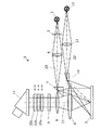
図1は、本発明に従う装置の一実施形態を示し、ここでは極めて簡素化されてモノスコーピック描写された、観察光線路21を有する蛍光手術用実体(立体)顕微鏡1の形式であり。蛍光手術用実体顕微鏡1は象徴的に図示された第1照明装置2を含んでおり、第1照明装置2は稼動状態において光を象徴的に図示された照明光線路20を介し、観察対象野7(オブジェクトフィールド)上へ配向する。図1の状態においてその光は観察対象野7上へ投射される励起光であり、その理由は、照明光線路20内において選択的に挿入可能な励起フィルタ3が挿入されているためである。照明光線路20内には象徴的に図示された従来どおりの別の構成部材が組み込まれている:従来どおりの第1照明光学系4と従来どおりの第1偏向プリズム5である。第1偏向プリズム5は光線方向(光線の進む方向)において蛍光手術用実体顕微鏡1の主対物レンズ6の手前に配設されており、照明光線路20を偏向し、主対物レンズ6を通して観察対象野7上へ指向させている。
FIG. 1 shows an embodiment of the device according to the invention, which is in the form of a fluorescent surgical entity (stereoscopic)
従って、励起フィルタ3(もしも挿入されているならば)と、照明光学系4と、偏向プリズム5と、主対物レンズ6(主対物レンズ6が勿論観察光線路21の構成部材でもあるという二重機能のもと)とは、第1照明光線路20を形成し、第1照明光線路20は励起フィルタ3の選択的な挿入により選択的に蛍光励起のための励起光線路となる。第1照明装置2ないし該装置内に備わっている光源が蛍光励起のために最適である狭帯域の非白色光源(例えばダイオードレーザ等)である場合には、励起フィルタ3は場合により省略することもできる。しかしそのような場合に上記の第1照明光線路20は専ら第1励起光線路であり、この第1励起光線路は主として蛍光励起のために用いられ、手術用顕微鏡照明としての使用にはその狭帯域光が原因で使用不可能である。その理由は、手術では通常はできるだけ自然に近い色再現を伴う光が望まれるためである。
Accordingly, the excitation filter 3 (if inserted), the illumination optical system 4, the deflecting
特にこの場合のために、また上記特許文献3におけるように第2照明装置による付加的な光増幅(additive Lichtverstaerkung)の場合のために、図1に従う構成には第2照明光線路22を有する第2照明装置12が設けられており、第2照明装置12は光を同様に観察対象野7上へ配向している。図1に図示された実施形態において第2照明光線路22には励起フィルタが設けられてなく、それ故、第2照明光線路22は励起光線路ではないか、又は狭帯域励起光照明装置を備えた励起光線路である。
Particularly for this case and for the case of additional light amplification by the second lighting device as in the above-mentioned
それに対し、図5(従来技術)において照明光線路22内には励起フィルタ3が設けられている。両方の光源は必要に応じて場合により対応するよう設計され、観察対象野7の照明時には互いに支援(サポート)し合い、又は択一的に択一的な色スペクトルを用いて使用することができる。
On the other hand, the
従って、図5のものは図1とほぼ同じ描写であり、本発明に従う一実施形態も図1に基づいて同様に説明される択一的な二分割式の照明光線路を含んでいる:この照明光線路は、励起フィルタ3を用いて選択的に励起光線路に変換することのできる、白色光照明装置2を備えた第1照明光線路20を有し、更に第2励起光線路22が設けられており、第2励起光線路22は励起時において励起照明装置からの励起光を観察対象野7上へ配向する。
Accordingly, FIG. 5 is substantially the same depiction as FIG. 1, and an embodiment according to the present invention also includes an alternative two-part illumination light line that is also described based on FIG. The illumination light line has a first
二分割式の照明光線路については、上記特許文献3の全記載内容、特に図1〜図4、これらの図面に関する段落11〜段落23の記載内容、そして明細書の段落6〜段落10の記載内容が参照される。尚、これらの記載事項は引用をもって本書に組込み記載されているものとする。
Regarding the two-divided illumination optical line, the entire description of
しかしながら勿論本発明は、唯一の照明光線路又は励起光線路を有する構成も含んでおり、その理由は、本発明によれば励起事象ないし照明光線路自体が重要なのではないためである。本発明によれば、照明光線路20及び/又は22ではなく観察光線路21が本発明に従うコントラスト調節(コントラスト設定)を行うために操作されることが重要である。
However, of course, the present invention also includes a configuration having only one illumination light line or excitation light line because the excitation event or the illumination light line itself is not important according to the present invention. According to the present invention, it is important that the observation
従って、本発明に従う蛍光手術用実体顕微鏡1は図示の実施形態によればオプションの第2照明装置12を含んでおり、第2照明装置12は同様に光を第2照明光学系13と第2偏向プリズム14を介して観察対象野7上へ投射する。本実施形態において第2偏向プリズム14は(観察光線路21の方向で見て)主対物レンズ6の後又は横に配設することができる。勿論本発明は、第2偏向プリズム14が第1偏向プリズム5と同様に対物レンズ6の前に配設されており従って第2照明光線路22の光が同様に主対物レンズ6を通って投射される構成も含んでいる。図1において両方の照明光線路20、22は1つの平面内で図示されている。しかしながら勿論これらの照明光線路20、22及びそれらの構成部材は空間的に相並んで、例えば主対物レンズ6に対して接線方向に相並んで配設することもできる。
Accordingly, the fluorescent
図1から見てとれるように、図示の実施形態において第1照明装置2の第1照明光線路20と観察光線路21とは蛍光手術用実体顕微鏡1の主対物レンズ6のところで(を介して)互いに交わっている。しかしながらこのことは強制的な条件ではない。また第1照明装置2の第1照明光線路20と第2照明装置12の第2照明光線路22とは観察光線路21の光学構成部材から完全に離れて、従って主対物レンズ6の脇を通り過ぎるように延在させることができる。その際、照明光線路ないし励起光線路20、22と観察光線路21とは主対物レンズ6と観察対象野7との間の空間内でのみ交わることになる。
As can be seen from FIG. 1, in the illustrated embodiment, the first
主対物レンズ6を介し、観察対象野7により反射された光と、場合により蛍光組織(蛍光を発する組織)により発光(放射)された発光光とが観察光線路21内へ導かれる。観察光線路21はその光学系について同様に象徴的に図示されており、顕微鏡光学系(例えばズーム)8と、従来どおり、選択的に挿入可能な第1観察フィルタ9とを含んでいる。この第1観察フィルタ9(遮断フィルタとも呼ばれる)の役割は主として発光光を通過させ、スペクトル的に他の光波長を吸収することである。しかしながらこの場合、第1観察フィルタ9は本発明の変形形態に応じ、周知のように、明らかに励起光の一部分に対しても、場合により白色光に至るまでの他の光波長の一部分に対しても、部分的に透過性であるように形成されている。従って観察者は一方では蛍光現象の発光を見ることができ、また追加的に背景光、即ち観察対象野7内の観察対象により反射された励起光(照射光)及び/又は白色光(背景照明)に至るまでの他の光波長の一部分を見ることができる。
Through the main
勿論第1観察フィルタ9は、その都度の蛍光時(その都度の発光光線)にとって最適の状態であるために様々な観察フィルタのグループから選択可能とすることもできる。
Of course, the
観察光線路21は、光方向(光の進む方向)において第1観察フィルタ9の後(図示した形態)又は前に、一セットの補助的な観察フィルタ10a、10b、10cを含んでおり、それに続き、接眼レンズを備えた実体鏡胴23を含んでいる。勿論図示の接眼レンズを備えた実体鏡胴23の代わりに又は接眼レンズに追加するかたちでビデオ鏡胴(Videotuben)のようなビデオ観察装置を装着することもできる。これらのビデオ観察装置は必要に応じて交換可能に設けることもできる。本発明においては観察光線路21の最終的な構造が重要なのではなく、本発明の本質的なことは、観察光線路21内の観察可能な光が選択的に(スライド)挿入可能な本発明に従う観察フィルタ10a〜10cの補助的なセット(少なくとも1つの第2観察フィルタ10)により観察対象野7の発光光と反射光との間のコントラストを調節することができるということである。
The observation
主対物レンズ6と、顕微鏡光学系8と、選択的に挿入可能な第1観察フィルタ9と、補助的な観察フィルタ10a〜10cの選択的に挿入可能なセット(少なくとも1つの第2観察フィルタ10)とは、観察光線路21の重要な部分を形成する。
A selectively insertable set (at least one second observation filter 10) of a main
図1に図示された蛍光手術用実体顕微鏡1の機能は、例えば以下のとおりである:
The function of the fluorescence
第1照明装置2は、極めて幅広の波長領域の光(例えば白色光)を放射する。従ってこの波長領域は、適用時には観察対象野7の領域内の観察対象の組織内にあるべきその都度の光増感剤(Photosensibilisator)のための励起波長領域も含んでいる。本実施形態において第1照明装置2の放出スペクトルは比較的広い(白色光スペクトル)ものとする。従って励起フィルタ3を使わない場合には基本的に手術用顕微鏡照明が提供され、この照明のもと外科医ないし利用者が観察対象野7内において手術を行う。蛍光励起時には、実質的に主として狭帯域の励起光を通過させる励起フィルタ3が(第1照明光線路20内へ)挿入される。第1照明装置2がいずれにせよ殆ど専ら励起波長領域内の励起光だけを発するという選択的モードの時には励起フィルタ3を省略することもできる(場合により選択的に取り外し可能に配設することもできる)。その際、そのような択一的な構成においてはいずれにせよ補助的な手術用顕微鏡照明が別個に配慮されているべきであり、例えば第2照明光線路22を介してである。しかしながら第1照明装置2が白色光源を有する場合には本実施形態において第1照明装置2は、一方では励起フィルタ3を使わないときは手術用顕微鏡照明のために用いられ、他方では励起フィルタ3を使うときは蛍光励起のために用いられることになる。
The
第1照明装置2からの光は、照明光学系4により集束され、偏向プリズム5へ導かれ、偏向プリズム5はこの光を偏向し、主対物レンズ6を介して観察対象野7上へ投射する。
Light from the
通常、観察対象野7内には、励起光を用いた照射のもと蛍光を発する区域(蛍光区域:フルオレセンスエリア)が存在する。観察対象野7により反射された励起光は発光光(蛍光)と共に主対物レンズ6と顕微鏡光学系8を介して更に導かれないし中間画像面上へ投射される。この際、このようにして観察対象野7によりもたらされた(観察対象野7から受光された)発光光及び反射光は、第1観察フィルタ9が主として蛍光波長領域内の発光光を通過させ、励起波長領域内の反射光も部分的に通過させ、他の波長の光は大部分をフィルタ除去するように第1観察フィルタ9によりフィルタリングされる。
Usually, in the
観察光線路21の延在形式に従い、観察対象野7の光は、観察光線路21内に配設された制御可能なスペクトル減衰(spektrale Abschwaechung)のための手段(補助的な観察フィルタ10a〜10c)により、特に励起波長領域内において限定されて必要に応じ(これらの手段(観察フィルタ10a〜10c)の選択又は設定により)更にフィルタリングされ、それにより発光光と反射光との間のコントラストが調節される。本実施形態においてこれらの手段は補助的な観察フィルタ10a〜10cにより形成されている。これらの観察フィルタ10a〜10cは、図1において矢印で示唆されているように、必要に応じ、励起波長領域内の光を減衰させ且つそのようにして中間画像面内へ投射される観察対象野の光のコントラストを目標を定めて変更するないし要求に適合させるためにオン作動又はオフ作動(即ち着脱)することができる。第2観察フィルタ10a〜10cがない場合には周辺光(反射光)に対する蛍光区域(発光光)の相対的な可視度(視感度)は減少されている。それに対し、第2観察フィルタないし複数の補助的な観察フィルタ10a〜10cがオン作動(即ち挿入)されている場合には観察対象野7により反射された励起光ないし観察対象野7により反射された光が以前よりも強く吸収され、その結果、吸収されない発光光で光っている蛍光区域が相対的により強く際立ち、従って蛍光現象に対する相対的な可視性が改善される。
According to the extended form of the observation
例示の観察光線路21は、接眼レンズを備えた鏡胴23を介し、非図示の観察者の非図示の目へ観察対象野7の画像を結像する。補助的に観察光線路21から、周知のように記録出力部等を設けることもでき、該記録出力部には例えばビデオカメラを配設することができる。あるいはまた観察光線路21は、例えばビデオ顕微鏡におけるように中間画像面内に画像センサ(例えばCCDセンサ、CMOSセンサ等)を備えることもでき、該画像センサは受信された中間画像を電子信号へ変換し、周知の方式により画面(ディスプレイ)上に表示するないし電子的に更に処理する。
The example observation
そのような構成は、図4に図示した一実施形態から見ることができる。 Such a configuration can be seen from one embodiment illustrated in FIG.
図4において象徴的に図示された顕微鏡1は、主対物レンズ6と、選択的に電気機械式制御機構100により観察光線路21内へ挿入される第1観察フィルタ9とを含んで構成されている。顕微鏡1は図1に従う構成と同様に少なくとも1つ、本実施形態では2つの補助的な観察フィルタ10を含んでいる。これらの観察フィルタ10は電気機械式で駆動ユニット100を用い又は手動でも、測定に基づき又は利用者の設定要求に基づき、選択的に又は同時に観察光線路21内へ(スライド)挿入されるか、ないし観察光線路21内において作動(活性)状態とされる。
The
図4において照明装置は図示されていないが、図1による照明装置に対応する照明装置が設けられているものとする。 Although the illumination device is not shown in FIG. 4, it is assumed that an illumination device corresponding to the illumination device according to FIG. 1 is provided.
既述のように、所定の励起光は、使用されている波長に応じ、光の強度が高すぎる場合ないし光線量が高すぎる場合、観察者の目を傷つける可能性がある。通常、無害強度をもちUV部分を伴わない青色励起光は、無害強度をもち赤外線部分(IR)の極めて僅かな近赤外線領域(NIR)からの赤色励起光と同様に目にとって問題ない。従って青色励起光(腫瘍学において典型的なALA蛍光)又は赤色励起光(血管造影法において典型的なNIR蛍光)は第1観察フィルタ9ないし補助的な観察フィルタ10a〜10cにより、観察光線路21が図1に図示され且つ同様に図4にも図示されているように鏡胴23と接眼レンズを備えた目で見るための観察光線路において終端し、これらを通して蛍光手術用実体顕微鏡1の利用者がのぞき見る場合にも、多少の差はあれともかくフィルタリングされずに透過することができる。このような方式により比較的簡単な技術手段を用いて蛍光区域の周辺の可視性の改善が可能となっている。
As described above, the predetermined excitation light may hurt the eyes of the observer if the light intensity is too high or the amount of light is too high depending on the wavelength used. Usually, blue excitation light having harmless intensity and no UV part is harmless to the eyes as red excitation light having harmless intensity and very little near infrared region (NIR) of the infrared part (IR). Accordingly, blue excitation light (ALA fluorescence typical in oncology) or red excitation light (NIR fluorescence typical in angiography) is transmitted through the
しかしながらそれに対して図4では、補助的な分光器(ビームスプリッタ)24が図示されている。分光器24は観察対象野7の画像を画像センサ11上へ偏向する。画像センサ11はビデオ画像処理ユニット400と接続されており、ビデオ画像処理ユニット400は、一方ではディスプレイ500と接続されており、他方では制御ユニット(PC(パーソナルコンピュータ)等)と接続されている。ディスプレイ500は、周知のように第三者用の観察のために用いることができ、また場合により、人間の目ではもはや感知されないが画像センサ11では記録することのできる光波領域内の発光現象の観察のためにも用いることができる。これらの発光現象は外部において、又は周知のように反射入射機構を用いて再度利用者に対して鏡胴23内において可視化することも可能である。しかしながらディスプレイ500は実質的に管理機能を有するであろう。
However, in FIG. 4, an auxiliary spectroscope (beam splitter) 24 is shown. The
制御ユニット200は、駆動ユニット100及び記憶及び/又は入力ユニット300と接続されている。記憶及び/又は入力ユニット300は、一方では制御ユニット200のデータないし設定内容の入力のために用いられ、他方ではディスプレイ500との通信のために用いられる。記憶部(メモリ)には入力ユニット300によりプログラミングされるかたちで、予め選択されたコントラスト設定内容を記憶させ、記憶部から必要に応じて呼び出すことができる。
The
画像センサ11、ビデオ画像処理ユニット400、制御ユニット200、駆動ユニット100の本発明に従う主機能は、調整回路(フィードバック調整回路)により及び適切な補助的な観察フィルタの(スライド)挿入により観察光線路21内において自動的に最適なコントラストを作ることである。
The main functions according to the invention of the
励起光の強度が増加すると、或いは波長が小さくなる又は波長が大きくなると、利用者の目に対する危険性が増加する(ライトハザード)、このことは、光強度が高い場合にも蛍光手術用実体顕微鏡1の利用者の目に対する危険性を生じさせないためにフィルタ選択時に考慮されなくてはならない。 When the intensity of the excitation light increases, or the wavelength decreases or increases, the risk to the user's eyes increases (light hazard). It must be taken into account when selecting a filter so as not to pose a danger to the eyes of one user.
従って、励起光の「危険性」は、励起光の強度の他にその波長にも依存する。利用者の目を有害光線から、特にUV光線又はIR光線から完全に守るためには、図1及び図4で図示されているように鏡胴23と接眼レンズを備えた目で見るための観察光線路の代わりに専ら中間画像面内の画像センサを使用することができ、該画像センサは利用者の目と異なり、一方では非可視光(例えばIR(赤外線))を可視光へ変換することができ、他方では高い光線強度にも比較的高いエネルギー光線にもさらすことができ、この際、画像センサ自体が害を受けることはない。この構成において利用者はディスプレイ(図4、500を参照)を介して画像情報を得ることになり、従って有害光線から保護されている。
Therefore, the “danger” of the excitation light depends not only on the intensity of the excitation light but also on its wavelength. In order to completely protect the user's eyes from harmful rays, in particular from UV rays or IR rays, as shown in FIGS. 1 and 4, an observation for viewing with an eye provided with a
励起光に対して追加し、観察対象野7を、第2照明装置12を用いて他の光スペクトルでも照射することができる。例えば第2照明装置12は観察対象野7の自然色を際立たせるために白色照明装置として構成することができる。好ましくは第1照明装置2の光と第2照明装置12の光との間の比率は、周知のように(蛍光手術用実体顕微鏡 Leica FL400を参照)変更可能であり、それにより観察対象野7内の蛍光区域も背景も所望どおりないし最適な状態で可視とされる(見ることができる)。
In addition to the excitation light, the
上記の蛍光手術用実体顕微鏡1は、単に例示としてとらえるべきである。勿論蛍光手術用実体顕微鏡1は更に非図示の別の構成部材を含むことができ、例えばズームのような別のレンズ系、又は光源からの光を減少させる虹彩絞り(アイリス絞り)のような光絞り等である。更に励起フィルタ3は照明光線路ないし励起光線路の他の位置に配設することもでき、例えば(照明光線方向で見て)照明光学系4の後又は偏向プリズム5の後である。同様に第1観察フィルタ9及び補助的な観察フィルタ10a〜10cも観察光線路の他の位置に配設することができる。特に補助的な観察フィルタ10a〜10cは観察光線路内において(観察光線方向で見て)第1観察フィルタ9の前に配設することができる。
The fluorescent
また、補助的な観察フィルタ10a〜10cのうちの幾つかを(観察光線方向で見て)第1観察フィルタ9の前に配設し、残りの補助的な観察フィルタを第1観察フィルタ9の後に配設することも可能である。更に本発明の基本思想を逸脱することなく光線路は任意に偏向することができ、例えば人間工学的(動作工学的)に旋回可能な鏡胴等を介してである。例えば偏向プリズムを観察光線路21の中間部の中央に形成することにより、ないし図5に例示されているようにあるいは Leica FL400 におけるように主対物レンズ6に対して中央に形成することにより、照明装置2及び12の照明光線路を観察光線路21と実質的に平行に配向させることができる。偏向プリズム5及び14の代わりに例えばミラーを設けることもできる。このことに関して本発明では光学系において最もよく知られた構成要素が用いられる。また第1観察フィルタ9と補助的な観察フィルタ10a〜10cが上記のような形式によりセンサによる情報読取の場合には中間画像面の前に配設され、直接的に目による情報読取の場合には接眼レンズの前に配設されているのであれば、光線路20、21、22の屈折要素又は偏向要素をいかに構成するかは本発明にとって重要なことではない。
Further, some of the auxiliary observation filters 10 a to 10 c are arranged in front of the first observation filter 9 (as viewed in the direction of the observation light beam), and the remaining auxiliary observation filters are arranged in the
それに加え、補助的な観察フィルタ10a〜10cは手動式で又は電動式で操作することができる。また補助的な観察フィルタ10a〜10cはスライド挿入又は旋回挿入することができる。
In addition, the
あるいはまた観察フィルタ9、10は、電気的に励起可能なLCDフィルタ(液晶ディスプレイフィルタ)としても構成することができ、これらのLCDフィルタは光線路内に常時置かれており、必要な応じて活性化される。 Alternatively, the observation filters 9, 10 can also be configured as electrically excitable LCD filters (liquid crystal display filters), which are always placed in the optical line and activated as needed. It becomes.
勿論、本発明の教示内容は、図示された蛍光手術用実体顕微鏡1だけに限らず、観察対象野7の蛍光区域を識別するための他の装置にも適用可能であり、例えば内視鏡等に適用可能である。
Of course, the teaching content of the present invention can be applied not only to the illustrated
図2a〜2cは、蛍光手術用実体顕微鏡1内で使用されるスペクトル光学ユニット(例えば照明装置及びフィルタ等)の様々なスペクトル延在曲線を示している。この際、横座標には波長λが記入されており、縦座標には規格化された光線強度及びフィルタの透過度θが記入されている。
2a to 2c show various spectral extension curves of a spectral optical unit (e.g. illuminator and filter) used in the fluorescence
第1照明装置2の放射スペクトルは、図2a〜2cにおいて一点鎖線Aで示されている。本実施形態において放射された光の強度はほぼ470nm以降の波長λにおいて比較的強く減少する。つまり典型的な青色光照明が用いられている。観察対象野7上へ照射される光のスペクトルを波長領域において更に限定するために第1照明装置2には図1に図示されているように励起フィルタ3が後置されている。励起フィルタ3の透過度のスペクトル延在曲線(即ち励起フィルタ3の透過曲線又は透過特性曲線)が鎖線Bで示されている。図面から見てとれるように励起フィルタ3は短波長励起波長領域において透過性である。従って励起波長の光のうち短波長部分だけが蛍光励起のために使用される。第1照明装置2からの光においてスペクトル的により長い波長部分は励起フィルタ3により吸収される。従ってこの波長部分は観察対象照明のためには使用されず、それに対し、前記短波長部分が全て励起のために使用される。
The radiation spectrum of the first illuminating
更に図2a〜2cには、第1観察フィルタ9の透過曲線C、並びに第2観察フィルタないし補助的な観察フィルタ10a〜10cの各々の透過曲線Da〜Dcが示されている。
2a to 2c show a transmission curve C of the
第2観察フィルタ10a〜10cは異なるスペクトル透過度を有する。つまり透過曲線Da〜Dcは横座標に沿って互いに相対的にスライドされている。従って異なる補助的な観察フィルタ10a〜10cは観察光線路21内の可視光の異なるスペクトル限定をもたらしてくれる。
The second observation filters 10a to 10c have different spectral transmittances. That is, the transmission curves Da to Dc are slid relative to each other along the abscissa. Thus, the different
更に図2a〜2cには可視励起波長領域E(斜線部)が示されており、この可視励起波長領域Eは励起フィルタ(曲線B)と第2観察フィルタ(曲線D)と照明装置(曲線A)との協働の結果、可視である。このことは、光であって観察対象野7により観察光線路21内へ反射されるのであれば観察光線路21内で感知することもできる光を意味している。上記領域E以外の波長領域、即ち例えば470nm〜570nmの間の波長領域は第1観察フィルタ(曲線C)により吸収されるので可視ではない(見ることはできない)。以下に説明するように発光波長の周辺の領域Fだけが例外となる。補助的な観察フィルタ10a〜10cによる励起光のスペクトル的な遮断が少ないほど、観察対象からの反射光が観察者に対してないし画像センサ11に対しても多くなる。
Further, FIGS. 2a to 2c show a visible excitation wavelength region E (shaded portion), which includes an excitation filter (curve B), a second observation filter (curve D), and an illumination device (curve A). ) Is visible as a result of collaboration with This means light that can be sensed in the observation
また、蛍光波長領域Fはほぼ600nmのところの蛍光波長において示されており、この蛍光波長の周辺において本実施形態では蛍光現象が発生する。 The fluorescence wavelength region F is shown at a fluorescence wavelength of approximately 600 nm, and a fluorescence phenomenon occurs in the present embodiment around this fluorescence wavelength.
本実施形態において、観察者により感知可能な励起光Eのスペクトル分布と輝度強度は使用されている第2観察フィルタ10a〜10cに依存して減少しているが、発光光Fの可視度(視感度)は一定である。このことが本発明に従うコントラストの調整可能性を明らかにしている。本発明の特別な一実施形態によれば補助的な観察フィルタ10a〜10cとして簡単な色ガラスフィルタを使用することもできるので、補助的な観察フィルタ10a〜10cを用いた調整可能性のためのコストが低く抑えられる。
In the present embodiment, the spectral distribution and luminance intensity of the excitation light E that can be perceived by the observer are reduced depending on the second observation filters 10a to 10c being used, but the visibility of the emitted light F (visual Sensitivity) is constant. This reveals the possibility of adjusting the contrast according to the present invention. According to a special embodiment of the present invention, simple colored glass filters can also be used as the
複数の補助的な観察フィルタ(補助フィルタ)10a〜10cが同時に使用されると、有効な透過曲線の傾斜に変更が生じ、それにより曲線の上昇勾配(上昇エッジ)が平坦化される(勾配が緩やかにされる)。 When a plurality of auxiliary observation filters (auxiliary filters) 10a to 10c are used simultaneously, the slope of the effective transmission curve changes, thereby flattening the rising slope of the curve (rising edge). Relaxed).
本実施形態では、その都度、補助的な観察フィルタ10a〜10cのうちの1つがオン作動される(即ち該観察フィルタを使用状態にする、具体的には該観察フィルタを観察光線路21内へ挿入する)とし、それに従い、図2a〜2cには各々の透過曲線(透過特性曲線)Da〜Dcが示されている。つまり図2aは透過特性曲線Daを有する補助的な観察フィルタ10aに関するグラフであり、図2bは透過特性曲線Dbを有する補助的な観察フィルタ10bに関するグラフであり、図2cは透過特性曲線Dcを有する補助的な観察フィルタ10cに関するグラフである。
In this embodiment, one of the auxiliary observation filters 10 a to 10 c is turned on each time (that is, the observation filter is put into use, specifically, the observation filter is put into the observation
観察対象野7へ入射する光は、実質的に照明装置のスペクトル特性により、そして励起フィルタ3の吸収特性(曲線B)によりカットオフされ(切り取られ)て定義される。それに対し、観察光線路21内の感知可能な光、即ち観察対象野7から一度主対物レンズ6を通って観察光線路21内へ入射された最終的に感知可能な光は、上記のように第1観察フィルタ9のフィルタ作用により、又は本発明に従って複数の補助的な観察フィルタ10a〜10cのうちの1つと第1観察フィルタ9との組み合わせにより定義される。図示された曲線から、この感知可能な光が本実施形態において短波長領域及び長波長領域から生じており、それに対して中央領域は第1観察フィルタ9(曲線C)により吸収されることが見てとれる。しかしながら長波長領域内では基本的に観察対象野7へ光は入射しないが、その理由は、その光は励起フィルタ3(曲線B)により吸収されるか、ないし図示の実施形態では第1照明装置2により初めから発生しない(曲線A)ためである。
The light incident on the
当業者にとって上記の記載内容から、フィルタの上記の組み合わせが本発明の限定として扱われていないことは明らかである。各々のフィルタの修正は他の結果をもたらす。本発明の本質の理解により、即ち補助的な観察フィルタ10a〜10cが選択的に第1観察フィルタ9を補助することにより、当業者にとって極めて異なる形態が可能となる。NIR領域のためのフィルタの組み合わせは例えば鏡面的に反転した曲線状況をもたらすであろう。また幾らか白色光が背景照明として可能とされる形態では中央波長領域内の第1観察フィルタ9の透過曲線Cが幾らか持ち上げられ、光源2の放出スペクトルが更に右側へスライドされるであろう、等など。
For those skilled in the art, it is clear from the above description that the above combinations of filters are not treated as limitations of the present invention. Each filter modification has other consequences. By understanding the essence of the invention, i.e. the
結果として図2aは次のことを示している。即ち観察光線路21内において、観察対象野7により反射された又は発光された光は第1観察フィルタ9(フィルタ特性曲線C)並びに第2観察フィルタ10a(フィルタ特性曲線Da)によりフィルタリングされる。それにより得られた曲線Eの下の可視スペクトルは斜線で示されており、発光曲線Fの下の可視スペクトル(蛍光波長領域からの光)と比べて比較的強い(intensiv)が、フィルタ曲線Daによるカットオフ(Beschneiden)を伴わない場合よりも強度は小さい。発光曲線Fの下の発光光は第1観察フィルタ9と第2観察フィルタ10aを妨害されずに透過する。従ってこの発光光は観察者にとって完全に可視である(見ることができる)。
As a result, FIG. 2a shows the following. That is, in the observation
結果として図2bは、第2観察フィルタ10aの代わりに他のフィルタ特性曲線Dbを有する第2観察フィルタ10bがオン作動(挿入)されている変更された状況を示している。それによると観察対象野7により反射された光のスペクトルは更に強く吸収される(結果として得られるスペクトルが曲線Eの下において再び斜線で示されている)。従って励起波長領域からの反射光は蛍光波長領域内の光に対して相対的に減衰され、それに対し、蛍光現象の発光光は図2aのように曲線Fの下にあって依然として妨害されずに透過する。従って蛍光手術用実体顕微鏡1の利用者は蛍光区域を相対的により強く感知できるが、その代償として可視周辺部は相対的により弱い感知となる。本発明に従い、観察対象自体における実際の照明状況ないし励起状況(励起光のスペクトル分布及び励起光の強度)は不変であることが重要である。このことは従来技術から公知のシステムに対する根本的な差異である。その結果、蛍光現象の発生のための励起状況を最適化することができ、それにもかかわらず利用者ないし外科医は自身のその都度の要求に従い、観察対象野からの発光光と反射光との間のコントラストを調節することができる。
As a result, FIG. 2b shows a modified situation in which the
最後に図2cは、補助的な観察フィルタ10a又は10bの代わりにフィルタ特性曲線Dcを有する第2観察フィルタ10cがオン作動(挿入)されている三番目の状況を示している。それによると観察対象野7により反射された光のスペクトルは短波長領域において図2bの状況におけるよりも更に強くフィルタリングされる(結果として得られるスペクトルが曲線Eの下において再び斜線で示されており、一段と幅狭となっている)。従って励起波長領域内の反射光は蛍光波長領域内の光に対して更に強く減衰ないしスペクトル的に限定される。従って蛍光手術用実体顕微鏡1の利用者は蛍光区域を比較的更に強く識別できるが、その代償として可視周辺部ないし背景は比較的更に弱い識別となる。
Finally, FIG. 2c shows a third situation in which the
従って、図2a〜2cから容易に見てとれるように、感知可能な周辺照明ないし背景照明、ないし背景光は、右方向への横座標に沿った補助的な観察フィルタ10a〜10cのフィルタ特性曲線Dのスライドが増えるに従い、主観的に感知可能な輝度も、客観的なスペクトル構成も変更させる。つまり第2観察フィルタ10a(図2a)において可視の光スペクトルは青紫色から青色を介して青緑色に至るまでの混合により形成され、それに対し、例えば第2観察フィルタ10c(図2c)において可視の光スペクトルは青緑色の方向へスライドされたスペクトルを含んでいる。
Thus, as can be easily seen from FIGS. 2a to 2c, the perceivable ambient or background illumination or background light is the filter characteristic curve of the
図3aは、図2a〜2cにおいて示された状況に極めて類似する変更状況を示しているが、本発明のこの変形形態では励起波長領域内において同じ透過特性を有し且つ個別に又は同時に観察光線路21内へ挿入することのできる例えば3つの補助的な観察フィルタ10a〜10cが設けられている。図3aには例えば1つだけの透過曲線Ddが示されており、この透過曲線Ddは図2a〜2cに従う各々の曲線Da〜Dcと比べると上昇勾配が明らかに小さく、短波長光の領域内の透過度も高くなっている。
FIG. 3a shows a modified situation that is very similar to the situation shown in FIGS. 2a-2c, but in this variant of the invention it has the same transmission characteristics in the excitation wavelength region and is either individually or simultaneously observed. For example, three
その都度有効なフィルタリングの程度ないし透過度(トランスミッション)は、補助的な観察フィルタ10a〜10cの1つ又は複数と第1観察フィルタ9とのその都度の加算により決められる。
The effective degree of filtering or transmission (transmission) in each case is determined by the respective addition of one or more of the auxiliary observation filters 10 a to 10 c and the
観察光線路21内において、観察対象野7により反射された光は第1観察フィルタ9(フィルタ特性曲線C)並びに第2観察フィルタ10a(図3による設計の場合にはフィルタ特性曲線Dd)によりフィルタリングされる。それにより得られたスペクトルは図3aでは曲線E下(可視励起波長領域)において再び斜線で示されている。図3aでは第2観察フィルタ10aだけによる減衰が示されている。更に別の第2観察フィルタ10b及び10cがオン作動(挿入)されると(同様にフィルタ特性Ddを有する)、その際には反射光のスペクトルは確かにスペクトル的に同じに留まるが、このスペクトルの強度は減少される。しかしながら図2a〜2cによる実施形態のもとでのようにより長い波長λへのスペクトルのスライドは行われない。
In the observation
従って上記実施形態では、観察者にとって調整時に背景光の異なる色感知が観察されるのではなく、蛍光現象のその都度の不変の可視発光光強度に対する強度減少だけが観察される。それにより同様にコントラストが変更される。 Therefore, in the above-described embodiment, different color perception of the background light is not observed for the observer at the time of adjustment, but only a decrease in the intensity of the fluorescent phenomenon with respect to the invisible visible light intensity at each time is observed. Thereby, the contrast is similarly changed.
図3bから、曲線Ddを適切に下降させるないし曲線Ddの上昇勾配を増加させる同一構成の2つの第2観察フィルタを備えた状況をみることができる。 From FIG. 3b it can be seen a situation with two second observation filters of the same configuration that appropriately lower the curve Dd or increase the ascending slope of the curve Dd.
図3a、3bにおける構成において、短波長励起波長領域内の可視領域(曲線E)はUV光方向において抑制されていないことを注目すべきである。従ってそこでは短波長の(観察者の目にとって有害な(ライトハザード)光)も観察光線路内において案内される。その結果、この形態は鏡胴と接眼レンズを用いた目による観察にはむしろ適しているとは言えず、従って図4に図示された、画像センサ11(この際、実体鏡胴(ステレオチューブ)23は伴わない)を用いた写真光学的ないしビデオ技術的な観察モードが条件とされれいる。 It should be noted that in the configuration in FIGS. 3a and 3b, the visible region (curve E) within the short wavelength excitation wavelength region is not suppressed in the UV light direction. Accordingly, short-wavelength light (light hazard light that is harmful to the eyes of the observer) is also guided there. As a result, it cannot be said that this configuration is rather suitable for observation with the eye using a lens barrel and an eyepiece, and accordingly, the image sensor 11 (in this case, a stereo lens barrel (stereo tube) shown in FIG. 23 is not accompanied by a photographic optical or video technical observation mode.
本発明の特別な一形態によれば、図4に例示されているように全てのフィルタ、即ち励起フィルタ3、照明フィルタ、観察フィルタ9、10は、電気機械式(駆動ユニット100)で各々の光線路20、21、22に対して着脱(取り付け及び取り外し)することができ、この際、駆動ユニット100の制御のためには制御ユニット200が設けられており、制御ユニット200は入力ユニット300を介してプログラミング可能であり、好ましくは例えば記憶ユニット内に予め設定されておりライトハザードを減少させるための安全用設定値(安全用セッティング)を使用することのできる状態にある。従ってここでは調整回路(フィードバック調整回路)を介して完全自動式でプログラミング可能なライトハザード用の安全用設定値がプログラミング可能である。これらの安全用設定値は、使用者自身が自分のために又は自分の目のために不利な設定内容を被らないことをもたらす。
According to a special embodiment of the invention, as illustrated in FIG. 4, all the filters, ie the
あるいはまた勿論、上記の全ての観察フィルタに対して補助的に、鏡胴内に固定で組み込まれるUVフィルタ等を組み込むこともでき、それによりライトハザードが適切に回避される。このことは全観察スペクトル(図3a、3b内の曲線E)内において曲線Eの強度の減少に対応するであろう。それにより曲線Eは、図2a〜2c内の曲線Eの勾配(エッジ)の1つにほぼ対応する初期勾配をもつであろう。従って観察光線路21のこのような一変形形態は目視観察にとっては有利であろうが、蛍光現象の発光光とUV近傍領域内の背景の反射光との間のコントラストを観察することができない可能性があるため、ビデオ支援式の観察にとっても同時に短所を伴うことになるだろう。従って観察者に対して特に短波長光により改善された構造情報を提供する所定の表面は、場合により最適な状態では感知されないことがある。従ってこの際、利用者は正しい妥協点を見い出さなくてはならない。本発明の基本的な教示内容のおかげで利用者には上記のように様々な方式が提供されている。
Alternatively, of course, a UV filter or the like that is fixedly incorporated in the lens barrel can be incorporated in addition to all the above-described observation filters, so that a light hazard is appropriately avoided. This will correspond to a decrease in the intensity of curve E in the entire observed spectrum (curve E in FIGS. 3a, 3b). Curve E will then have an initial slope that roughly corresponds to one of the slopes (edges) of curve E in FIGS. Therefore, such a modified form of the observation
図1に図示された第2照明装置12が追加的にオン(点灯)とされると、図2a〜2c並びに図3a、3bに図示されたスペクトルないし波長領域には追加的に第2照明装置12のスペクトルが重ね合わされる。この第2照明装置12が白色光を放出するとした場合、この白色光は、図2a〜2c並びに図3a、3bに図示されたグラフにおいて曲線Aの右部分の上昇をもって表せるであろう。勿論この白色光には同様に第1観察フィルタ9並びに、使用状況に応じ、補助的な観察フィルタ10a〜10cが作用する。従って白色光を強すぎない程度でスペクトル的に吸収するためには、例えば第1観察フィルタ9(吸収特性曲線C)が中央の波長領域において完全に吸収を行うのではなく、中央の波長領域においても光の一部分を通過させるという構成が考えられる。もっともこのような措置には図2に従う補助的な観察フィルタ10a〜10cが影響を及ぼすことはないだろう。つまり中央の波長領域内の照明光の感知可能性は発光光(F)に比肩しむしろ一定に留まるであろう。しかしながら図3a、3bに従う構成ではこのスペクトル領域もその可視性(視感性)において調整されるであろう(蛍光現象の発光光に対する相対的なコントラスト適合)。
When the second illuminating
好ましくは、第1観察フィルタ9は干渉フィルタとして形成される。更に好ましくは第2観察フィルタ10a〜10cは材料において着色されたフィルタ(色ガラスフィルタ又は色プラスチックフィルタ)として形成される。従って第2観察フィルタ10a〜10cは第1観察フィルタ9よりも遥かに少ない製造コストで済む。
Preferably, the
最後に、本発明に従う蛍光手術用実体顕微鏡1の上記の実施形態は多種多様な可能性からの一部分を提示しているにすぎず、本発明の適用領域を限定するために援用されるべきではないことを指摘する。勿論上記の実施形態は任意に組み合わせたり変更したりすることができる。例えば図2a〜2c並びに図3a、3bからの教示内容を、例えば透過曲線Da〜Dc及びDdを有する第2観察フィルタ10a〜10cを組み合わせることにより組み合わせることができる。
Finally, the above-described embodiment of the fluorescence
別個の第1観察フィルタ9と第2観察フィルタ10a〜10cの代わりに、組み合わされた唯一のフィルタを使用することもでき、該フィルタは例えば(第2フィルタの機能のための)材料において着色されたガラスを有する(第1観察フィルタの機能のための)干渉フィルタとして構成することもできる。例えばそのために第1観察フィルタ9の透過曲線Cは、第1コンビネーションフィルタを得るために第2観察フィルタ10aの透過曲線Daと組み合わされる。勿論この際には本発明に従い、少なくとも2つの異なるコンビネーション観察フィルタ9を設けなくてはならない。同じように例えば第1観察フィルタ9の透過曲線Cを、第2コンビネーションフィルタを得るために第2観察フィルタ10bの透過曲線Dbと組み合わせることができるであろう。
Instead of a separate
当業者にとって、上記考察内容に基づき、本発明の保護範囲を逸脱することなく本発明を当業者の要求に適合させることは容易であると認められる。それに加え、図面に図示された装置の部材は、独立発明のための基礎を形成することができることも指摘しておく。既述のように本発明は蛍光手術用実体顕微鏡だけに限定されるものではないことを特に指摘しておく。本発明の技術的な基本思想は蛍光手術用実体顕微鏡構造以外でも有効に適用することができる。本願の請求項において及びそれに付随する本明細書の部分において「蛍光手術用実体顕微鏡」との記載は単に「顕微鏡又は拡大装置」とも読めるものとする。つまり本発明は、例えば上記特許文献5に従うようなルーペメガネ(ここでは観察フィルタ(6)に対して補助的に本発明に従って第2観察フィルタ10が組み込まれるであろう)なども含んでおり、ただしそれらのルーペメガネがその特別な形態に基づいて選択的に蛍光観察及び/又は手術のために用いられる場合にである。従って本願の特許請求項では広い範囲が請求されている。特別な場合として本発明にはモノスコーピック拡大装置も含まれる(例えば内視鏡におけるもの)。因みに蛍光手術用実体顕微鏡は、公知のごとく例えば生物学や、例えば鉱物学や法医学等の技術分野においても適用可能である。
Based on the above considerations, it will be recognized by those skilled in the art that it is easy to adapt the present invention to those skilled in the art without departing from the scope of protection of the present invention. In addition, it should be pointed out that the components of the device illustrated in the drawings can form the basis for an independent invention. As mentioned above, it should be particularly pointed out that the present invention is not limited to a fluorescence surgical stereomicroscope. The technical basic idea of the present invention can be effectively applied to structures other than the fluorescence microscope stereomicroscope structure. In the claims of this application and in the part of this specification that accompanies it, the description of "fluorescent surgical stereomicroscope" shall be read simply as "microscope or magnifying device". That is, the present invention also includes, for example, magnifying glasses according to Patent Document 5 (here, the
あるいはまた励起フィルタ3の選択的な交換において、手術用顕微鏡照明の改善のために用いられる照明フィルタを設けることもできる。そのような照明フィルタは必要に応じて第2照明装置の前にも設けることができる。
Alternatively, in the selective exchange of the
特許請求項11〜15の特徴は、これらの特許請求項以前の特許請求項の特徴と相互に依存し、手術用顕微鏡のための適用可能性の最適化のためのものである。これらの適用可能性は既述のように照明の最適化に従事しているので、これらの適用可能性により、観察対象野7が最適の状態で照明ないし励起され、それにより第1観察フィルタ9と第2観察フィルタ10によるコントラスト選択が最適の状態となりえることを保証することができる。
The features of
尚、本発明の全開示(特許請求の範囲及び図面を含む)の枠内において、更にその基本的技術思想に基づいて、実施例ないし実施形態の変更、調整が可能である。また、本発明の特許請求の範囲の枠内において種々の開示要素の多様な組み合わせないし選択が可能である。即ち、本発明は、特許請求の範囲及び図面を含む全開示、技術的思想に従って当業者であればなし得るであろう各種変形、修正を含むことは勿論である。 It should be noted that the examples and the embodiments can be changed and adjusted within the scope of the entire disclosure (including claims and drawings) of the present invention and based on the basic technical concept. In addition, various combinations or selections of various disclosed elements are possible within the scope of the claims of the present invention. That is, the present invention naturally includes various modifications and changes that could be made by those skilled in the art according to the entire disclosure including the claims and the drawings, and the technical idea.
1 唯一の観察光線路21を有する蛍光手術用実体顕微鏡(模式図)
2 第1照明装置
3 励起フィルタ
4 照明光学系
5 第1偏向プリズム
6 主対物レンズ
7 検査ないし観察すべき観察対象ないし観察対象野
8 顕微鏡光学系、例えばズーム等
9 観察光線路21内の第1観察フィルタ
10a、10b、10c 観察光線路21内の第2観察フィルタ
11 画像センサ
12 第2照明装置(純粋な手術照明用)又は補助的な第2照明装置(手術照明の増加のため又は励起照明の増加のため又は背景照明の増加のため)
13 第2照明装置12のための第2照明光学系
14 第2照明光線路22のための第2偏向プリズム
20 第1照明光線路
21 観察光線路
22 択一的な第2照明光線路(純粋な手術照明用)又は補助的な第2照明光線路(手術照明の増加のため又は励起照明の増加のため又は背景照明の増加のため)
23 実体鏡胴(ステレオチューブ)
24 分光器(ビームスプリッタ)
25 フィルタ制御のためのハンドスイッチ
26 フィルタ制御のためのフットスイッチ
27 通信ラインないし制御ライン
100 駆動ユニット、電動式、電気機械式、手動式
200 制御ユニット、例えばPC(パーソナルコンピュータ等)
300 記憶ユニット(メモリユニット)、入力ユニット
400 ビデオ画像処理ユニット
500 ディスプレイ
A 第1照明装置2の発光スペクトルの曲線
B 励起フィルタ3の透過曲線ないし透過特性曲線
C 第1観察フィルタ9の透過曲線ないし透過特性曲線
Da、Db、Dc、Dd 第2観察フィルタ10の透過曲線ないし透過特性曲線
E 反射された可視励起波長領域の曲線
F 発光された可視蛍光波長領域(蛍光現象の発光光)の曲線
1 Fluorescent surgical stereo microscope with a single observation beam 21 (schematic diagram)
2
13 Second illumination
23 Stereoscope (stereo tube)
24 Spectrometer (beam splitter)
25 Hand switch for
300 storage unit (memory unit),
A Transmission curve or transmission characteristic curve C of the
Claims (15)
− 励起稼動状態では前記観察対象野(7)を、少なくとも1つの照明光線路(20、22)を介して励起波長領域(E)内の光で照射し、手術稼動状態では前記観察対象野(7)を、前記少なくとも1つの照明光線路(20、22)を介して照明波長領域内の光で照射する第1照明装置(2)と、
− 前記観察対象野(7)によりもたらされた反射光及び発光光を案内するための観察光線路(21)と、
− 前記励起波長領域(E)内及び発光波長領域(F)内において透過性である、前記観察光線路(21)内の第1観察フィルタ(9)と
を含んで構成されること、
前記観察光線路(21)内に選択的に配設可能な少なくとも1つの第2観察フィルタ(10a〜10c)が設けられており、該第2観察フィルタは、観察者に対する前記励起波長領域(E)内の可視光を制御可能に減衰するため及び/又は制御可能にスペクトル変更するように少なくとも部分的に吸収性であり、更に該第2観察フィルタは、前記発光光(F)に対して完全に透過性であること
を特徴とする蛍光手術用実体顕微鏡。 A fluorescent surgical stereomicroscope (1) for identifying a fluorescent area of an observation target in an observation target field (7), the fluorescent surgical stereomicroscope being
Irradiating the observation target field (7) with light in the excitation wavelength region (E) through at least one illumination light line (20, 22) in the excitation operation state; 7) illuminating with light in the illumination wavelength region via the at least one illumination light line (20, 22),
An observation light line (21) for guiding the reflected and emitted light provided by the observation field (7);
-Comprising a first observation filter (9) in the observation optical line (21) that is transparent in the excitation wavelength region (E) and in the emission wavelength region (F);
At least one second observation filter (10a to 10c) that can be selectively disposed in the observation optical line (21) is provided, and the second observation filter includes the excitation wavelength region (E ) At least partly absorptive to controllably attenuate visible light and / or controllably spectrally change, and the second viewing filter is completely radiant to the emitted light (F) Stereoscopic microscope for fluorescent surgery, characterized in that it is transparent.
を特徴とする、請求項1に記載の蛍光手術用実体顕微鏡。 The at least one second observation filter (10a to 10c) is provided with at least one auxiliary observation filter (10b, 10c) that can be turned on alternatively or additionally. The observation filter has the same or different absorption characteristics as the second observation filter (10a) with respect to light in the excitation wavelength region (E) and is at least partially absorptive. The fluorescence surgical stereomicroscope according to claim 1.
を特徴とする、請求項2に記載の蛍光手術用実体顕微鏡。 A plurality of auxiliary observation filters (10a to 10c) that can be selectively inserted are provided, and the auxiliary observation filters have different light transmission characteristics relatively different from each other in the excitation wavelength region (E). The fluorescent microscope stereomicroscope according to claim 2, comprising (Da to Dc).
を特徴とする、請求項1又は2に記載の蛍光手術用実体顕微鏡。 A plurality of auxiliary observation filters (10a to 10c) that can be selectively inserted are provided, and the auxiliary observation filters have the same light transmission characteristics (Dd) in the excitation wavelength region (E). Further, the fluorescence surgical stereomicroscope according to claim 1 or 2, characterized in that it can be additionally turned on.
を特徴とする、請求項1〜4のいずれか一項に記載の蛍光手術用実体顕微鏡。 At least one excitation filter (3) is provided in at least one of the illumination light lines (20, 22), and the excitation filter is transmissive in the excitation wavelength region (E), but the light emission The fluorescent surgical stereomicroscope according to any one of claims 1 to 4, wherein the fluorescent microscope is absorbable in the wavelength region (F).
を特徴とする、請求項1〜5のいずれか一項に記載の蛍光手術用実体顕微鏡。 The excitation filter (3) has high-pass / low-pass characteristics, whereas the at least one second observation filter (10a-10c) has low-pass / high-pass characteristics. The fluorescence surgical stereomicroscope according to any one of the above.
を特徴とする、請求項1〜6のいずれか一項に記載の蛍光手術用実体顕微鏡。 The first observation filter (9) is formed as an interference filter, and the at least one second observation filter (10a to 10c) is formed as a colored glass filter or a colored plastic filter colored in the material. A stereomicroscope for fluorescent surgery according to any one of claims 1 to 6, characterized in that
を特徴とする、請求項1〜7のいずれか一項に記載の蛍光手術用実体顕微鏡。 The second illuminating device (12) that emits a second wavelength region that is different from and / or wider than the first illuminating device (2) is turned on relative to the first illuminating device (2). 8. The device according to claim 1, wherein the second lighting device can be switched on alternatively to the first lighting device. Stereoscopic microscope for fluorescence operation according to item.
− 電子的に設定可能なコントラストが達成されるように、前記少なくとも1つの第2観察フィルタ(10a〜10c)ないし前記補助的な観察フィルタ(10a〜10c)を制御するための制御手段(100、200)とが設けられていること
を特徴とする、請求項1〜8のいずれか一項に記載の蛍光手術用実体顕微鏡。 The contrast between the reflected light part in the excitation wavelength region (E) and the emitted light part in the emission wavelength region (F) from the observation field (7) to the image sensor (11); Video assisted image processing means (400) for automatically evaluating the light received at
Control means (100, 100) for controlling the at least one second observation filter (10a-10c) or the auxiliary observation filter (10a-10c) so that an electronically configurable contrast is achieved. 200) is provided. The stereoscopic microscope for fluorescent surgery according to any one of claims 1 to 8, wherein:
を特徴とする、請求項1〜9のいずれか一項に記載の蛍光手術用実体顕微鏡。 10. The setting content selected for the at least one second observation filter (10a to 10c) can be stored in the storage unit (300) and can be recalled again. The fluorescence surgical stereomicroscope according to any one of the above.
を特徴とする、請求項1〜10のいずれか一項に記載の蛍光手術用実体顕微鏡。 11. The first illumination device (2) and the second illumination device (12), respectively, each excitation filter (3) can optionally be placed after the first illumination device (2) and the second illumination device (12) A fluorescent surgical stereomicroscope according to claim 1.
を特徴とする、請求項11に記載の蛍光手術用実体顕微鏡。 The first illumination device (2) and the second illumination device (12), alternatively, each for providing a totally optimized white light illumination for the excitation filter (3) The stereoscopic microscope for fluorescent surgery according to claim 11, wherein different illumination filters can be placed later.
を特徴とする、請求項1〜12のいずれか一項に記載の蛍光手術用実体顕微鏡。 The excitation filter (3), the illumination filter, and the observation filter (9, 10) are attached to and detached from the optical lines (20, 21, 22) in an electromechanical manner using a drive unit (100). And a control unit (200) is provided for controlling the electromechanical mechanism, and the control unit (200) is programmable via the input unit (300). The stereomicroscope for fluorescent surgery according to any one of claims 1 to 12.
を特徴とする、請求項8〜13のいずれか一項に記載の蛍光手術用実体顕微鏡。 The first illuminating device (2) and the second illuminating device (12) are disposed apart from the fluorescent surgical stereomicroscope (1). The optical waveguides are connected to each other through the first to second optical systems (4, 13) and the first to second deflecting prisms (5, 14). The fluorescent microscope stereomicroscope according to any one of claims 8 to 13, characterized in that the fluorescent microscope is oriented to an observation target field (7).
を特徴とする、請求項14に記載の蛍光手術用実体顕微鏡。 One of the first and second deflecting prisms (5, 14) is disposed between the main objective lens (6) and the observation target field (7), while the other deflecting prism ( 5) is disposed between the main objective lens (6) and an end of the observation optical line (21) opposite to the observation target field (7). Item 15. A stereoscopic microscope for fluorescent surgery according to Item 14.
Applications Claiming Priority (2)
| Application Number | Priority Date | Filing Date | Title |
|---|---|---|---|
| DE102010044503.7A DE102010044503B4 (en) | 2010-09-06 | 2010-09-06 | Operations fluorescence stereomicroscope |
| DE102010044503.7 | 2010-09-06 |
Publications (2)
| Publication Number | Publication Date |
|---|---|
| JP2012058732A true JP2012058732A (en) | 2012-03-22 |
| JP5945104B2 JP5945104B2 (en) | 2016-07-05 |
Family
ID=45595431
Family Applications (1)
| Application Number | Title | Priority Date | Filing Date |
|---|---|---|---|
| JP2011193638A Active JP5945104B2 (en) | 2010-09-06 | 2011-09-06 | Fluorescent surgical stereo microscope |
Country Status (3)
| Country | Link |
|---|---|
| US (1) | US8614851B2 (en) |
| JP (1) | JP5945104B2 (en) |
| DE (1) | DE102010044503B4 (en) |
Cited By (3)
| Publication number | Priority date | Publication date | Assignee | Title |
|---|---|---|---|---|
| JP2016017876A (en) * | 2014-07-09 | 2016-02-01 | 日本板硝子株式会社 | Fluorescence detection optical device |
| JPWO2016194699A1 (en) * | 2015-06-02 | 2018-04-12 | 国立大学法人旭川医科大学 | Observation assistance device, information processing method, and program |
| JP2019035773A (en) * | 2018-12-05 | 2019-03-07 | 日本板硝子株式会社 | Fluorescence detection optical device |
Families Citing this family (18)
| Publication number | Priority date | Publication date | Assignee | Title |
|---|---|---|---|---|
| US8810905B2 (en) * | 2012-01-30 | 2014-08-19 | Kenneth W. Bauer | Stereomicroscope fluorescence system |
| DE102012001854A1 (en) | 2012-02-01 | 2013-08-01 | Leica Microsystems (Schweiz) Ag | Special lighting Operations stereomicroscope |
| FR2989876B1 (en) * | 2012-04-25 | 2014-04-18 | Fluoptics | FLUORESCENCE IMAGING SYSTEM FOR AN OPERATIVE BLOCK |
| DE102012221955A1 (en) * | 2012-11-30 | 2014-06-05 | Leica Microsystems (Schweiz) Ag | Illumination device for a surgical microscope |
| DE102014107445A1 (en) * | 2014-05-27 | 2015-12-03 | Carl Zeiss Meditec Ag | An optical observation apparatus, a method for setting a parameter value for an optical observation apparatus, and a method for recording image or video data from an observation object by means of an observation optical apparatus |
| DE102014008243A1 (en) * | 2014-05-27 | 2015-12-03 | Carl Zeiss Meditec Ag | Fluorescence observation system and optical filter system therefor |
| DE102014016850B9 (en) * | 2014-11-13 | 2017-07-27 | Carl Zeiss Meditec Ag | Optical system for fluorescence observation |
| WO2016130424A1 (en) | 2015-02-09 | 2016-08-18 | The Arizona Board Of Regents Of Regents On Behalf Of The University Of Arizona | Augmented stereoscopic microscopy |
| DE102015003681B4 (en) | 2015-03-24 | 2023-12-21 | Karl Storz Se & Co. Kg | Device for recording an image of an object field on a human or animal body |
| DE102015216570A1 (en) * | 2015-08-31 | 2016-11-03 | Carl Zeiss Meditec Ag | microscopy system |
| DE102016111730B3 (en) * | 2016-06-27 | 2017-12-28 | Leica Microsystems Cms Gmbh | Lighting device and microscope with such a lighting device |
| US10324041B2 (en) * | 2016-12-21 | 2019-06-18 | Abbott Japan Co., Ltd. | Optical imaging system using lateral illumination for digital assays |
| CN110431464A (en) * | 2017-03-22 | 2019-11-08 | 诺华股份有限公司 | Reconfigurable surgical operation microscope |
| DE102017216754B4 (en) * | 2017-09-21 | 2024-03-28 | Carl Zeiss Meditec Ag | Surgical microscope with an illumination device |
| IT201800002665A1 (en) * | 2018-02-14 | 2019-08-14 | Giuseppe Perna | SURGICAL MICROSCOPE |
| DE102019101773B9 (en) * | 2019-01-24 | 2021-11-25 | Carl Zeiss Meditec Ag | Microscopy system and method for operating a microscopy system |
| DE102019115276A1 (en) * | 2019-06-06 | 2020-12-10 | Karl Storz Se & Co. Kg | Light source and system for and method for fluorescence diagnosis |
| DE102020124686B9 (en) | 2020-09-22 | 2023-08-03 | Carl Zeiss Meditec Ag | Filter set, fluorescence observation system and method for simultaneous observation of fluorescent and non-fluorescent areas of an object |
Citations (19)
| Publication number | Priority date | Publication date | Assignee | Title |
|---|---|---|---|---|
| JPH02149246A (en) * | 1988-12-01 | 1990-06-07 | Topcon Corp | Fundus camera |
| JPH0351333U (en) * | 1989-09-22 | 1991-05-20 | ||
| JPH05150164A (en) * | 1991-11-29 | 1993-06-18 | Olympus Optical Co Ltd | Vartical fluorescence microscope |
| US5371624A (en) * | 1991-11-29 | 1994-12-06 | Olympus Optical Co., Ltd. | Reflected fluorescence microscope |
| JPH09497A (en) * | 1995-06-19 | 1997-01-07 | Fuji Photo Film Co Ltd | Fluorescent image diagnostic device |
| JPH1176146A (en) * | 1997-09-01 | 1999-03-23 | Olympus Optical Co Ltd | Optical device |
| JPH11352409A (en) * | 1998-06-05 | 1999-12-24 | Olympus Optical Co Ltd | Fluorescence detector |
| JP2000097859A (en) * | 1998-09-24 | 2000-04-07 | Olympus Optical Co Ltd | Fluorescence observing method and device |
| JP2001149317A (en) * | 1999-11-26 | 2001-06-05 | Canon Inc | Eyeground camera device |
| JP2002291682A (en) * | 2001-04-02 | 2002-10-08 | Olympus Optical Co Ltd | Endoscope system for fluorescent observation |
| US20030227674A1 (en) * | 2002-06-05 | 2003-12-11 | Nikon Corporation | Epi-illumination apparatus for fluorescent observation and fluorescence microscope having the same |
| JP2004012702A (en) * | 2002-06-05 | 2004-01-15 | Nikon Corp | Vertical illuminator for fluorescent observation and fluorescent microscope provided therewith |
| JP2004163413A (en) * | 2002-08-28 | 2004-06-10 | Carl-Zeiss-Stiftung Trading As Carl Zeiss | Microscope system and microscope inspection method |
| US20040178356A1 (en) * | 2002-08-29 | 2004-09-16 | Olympus Optical Co., Ltd. | Laser scanning microscope |
| JP2006221167A (en) * | 2005-02-09 | 2006-08-24 | Leica Microsystems (Schweiz) Ag | Fluorescence/infrared device for medical operation microscope |
| EP1728464A1 (en) * | 2005-06-03 | 2006-12-06 | Olympus Medical Systems Corp. | Endoscope image pickup system |
| EP1769730A1 (en) * | 2004-07-06 | 2007-04-04 | Olympus Corporation | Light source device and fluorescence observation system |
| US20080240528A1 (en) * | 2005-05-25 | 2008-10-02 | Jurgen Tumpner | Method and Device for Scanning a Sample with Contrast Evaluation |
| JP2009525495A (en) * | 2006-01-30 | 2009-07-09 | カール ツァイス サージカル ゲーエムベーハー | Microscope system |
Family Cites Families (11)
| Publication number | Priority date | Publication date | Assignee | Title |
|---|---|---|---|---|
| DE19548913A1 (en) | 1995-12-31 | 1997-07-03 | Storz Karl Gmbh & Co | Diagnostic device for photosensitised reaction in living tissue |
| EP0930843B1 (en) | 1997-04-02 | 2004-02-25 | Karl Storz GmbH & Co. KG | Device for photodynamic diagnosis |
| DE19804797A1 (en) | 1998-02-07 | 1999-08-12 | Storz Karl Gmbh & Co | Device for endoscopic fluorescence diagnosis of tissue |
| JP2001166214A (en) * | 1999-12-03 | 2001-06-22 | Olympus Optical Co Ltd | Optical device |
| DE10252313B9 (en) | 2002-11-11 | 2006-10-19 | Carl Zeiss | Investigation system for the simultaneous direct visualization of a fluorescent label and a tissue region surrounding the fluorescent label and method of investigation therefor |
| DE10355523A1 (en) * | 2003-11-21 | 2005-08-11 | Carl Zeiss Jena Gmbh | Epi-fluorescence stereomicroscope |
| DE102006047723A1 (en) * | 2006-08-25 | 2008-02-28 | Carl Zeiss Surgical Gmbh | Surgical microscope with illumination device |
| EP1930843A1 (en) * | 2006-12-07 | 2008-06-11 | Axalto SA | Backing film adapted for preventing electronic module electrostatic discharges and method of manufacturing a module implementing the backing film |
| DE102007034936A1 (en) | 2007-07-23 | 2009-01-29 | Friedrich-Schiller-Universität Jena | Weak fluorescent area recognizing device for recognition of pathological changes of e.g. skin, has portion of radiation defined such that intensity of radiation and intensity of fluorescence led to signals with imaging detection system |
| DE102008034008B4 (en) * | 2008-07-21 | 2010-07-01 | Carl Zeiss Surgical Gmbh | Filter kit for the observation of fluorescence radiation in biological tissue |
| DE102008062650B9 (en) * | 2008-12-17 | 2021-10-28 | Carl Zeiss Meditec Ag | Surgical microscope for observing infrared fluorescence and methods for this |
-
2010
- 2010-09-06 DE DE102010044503.7A patent/DE102010044503B4/en active Active
-
2011
- 2011-09-06 US US13/225,626 patent/US8614851B2/en active Active
- 2011-09-06 JP JP2011193638A patent/JP5945104B2/en active Active
Patent Citations (26)
| Publication number | Priority date | Publication date | Assignee | Title |
|---|---|---|---|---|
| JPH02149246A (en) * | 1988-12-01 | 1990-06-07 | Topcon Corp | Fundus camera |
| JPH0351333U (en) * | 1989-09-22 | 1991-05-20 | ||
| JPH05150164A (en) * | 1991-11-29 | 1993-06-18 | Olympus Optical Co Ltd | Vartical fluorescence microscope |
| US5371624A (en) * | 1991-11-29 | 1994-12-06 | Olympus Optical Co., Ltd. | Reflected fluorescence microscope |
| JPH09497A (en) * | 1995-06-19 | 1997-01-07 | Fuji Photo Film Co Ltd | Fluorescent image diagnostic device |
| JPH1176146A (en) * | 1997-09-01 | 1999-03-23 | Olympus Optical Co Ltd | Optical device |
| JPH11352409A (en) * | 1998-06-05 | 1999-12-24 | Olympus Optical Co Ltd | Fluorescence detector |
| US6094274A (en) * | 1998-06-05 | 2000-07-25 | Olympus Optical Co., Ltd. | Fluorescence detecting device |
| JP2000097859A (en) * | 1998-09-24 | 2000-04-07 | Olympus Optical Co Ltd | Fluorescence observing method and device |
| JP2001149317A (en) * | 1999-11-26 | 2001-06-05 | Canon Inc | Eyeground camera device |
| US6456787B1 (en) * | 1999-11-26 | 2002-09-24 | Canon Kabushiki Kaisha | Eye fundus camera |
| JP2002291682A (en) * | 2001-04-02 | 2002-10-08 | Olympus Optical Co Ltd | Endoscope system for fluorescent observation |
| US20030227674A1 (en) * | 2002-06-05 | 2003-12-11 | Nikon Corporation | Epi-illumination apparatus for fluorescent observation and fluorescence microscope having the same |
| JP2004012702A (en) * | 2002-06-05 | 2004-01-15 | Nikon Corp | Vertical illuminator for fluorescent observation and fluorescent microscope provided therewith |
| JP2004163413A (en) * | 2002-08-28 | 2004-06-10 | Carl-Zeiss-Stiftung Trading As Carl Zeiss | Microscope system and microscope inspection method |
| US20080013166A1 (en) * | 2002-08-28 | 2008-01-17 | Michael Haisch | Microscopy system, microscopy method, and a method of treating an aneurysm |
| US20040178356A1 (en) * | 2002-08-29 | 2004-09-16 | Olympus Optical Co., Ltd. | Laser scanning microscope |
| JP2010152397A (en) * | 2002-08-29 | 2010-07-08 | Olympus Corp | Laser scanning microscope |
| EP1769730A1 (en) * | 2004-07-06 | 2007-04-04 | Olympus Corporation | Light source device and fluorescence observation system |
| JP2006221167A (en) * | 2005-02-09 | 2006-08-24 | Leica Microsystems (Schweiz) Ag | Fluorescence/infrared device for medical operation microscope |
| US20060198001A1 (en) * | 2005-02-09 | 2006-09-07 | Roger Spink | Fluorescence/infrared device for surgical microscopes |
| US20080240528A1 (en) * | 2005-05-25 | 2008-10-02 | Jurgen Tumpner | Method and Device for Scanning a Sample with Contrast Evaluation |
| JP2008542800A (en) * | 2005-05-25 | 2008-11-27 | オリンパス・ソフト・イメージング・ソリューションズ・ゲゼルシャフト・ミト・ベシュレンクテル・ハフツング | Method and apparatus for scanning a sample by evaluating contrast |
| EP1728464A1 (en) * | 2005-06-03 | 2006-12-06 | Olympus Medical Systems Corp. | Endoscope image pickup system |
| JP2009525495A (en) * | 2006-01-30 | 2009-07-09 | カール ツァイス サージカル ゲーエムベーハー | Microscope system |
| US20100110538A1 (en) * | 2006-01-30 | 2010-05-06 | Carl-Zeiss Surgical Gmbh | Microscope system |
Cited By (3)
| Publication number | Priority date | Publication date | Assignee | Title |
|---|---|---|---|---|
| JP2016017876A (en) * | 2014-07-09 | 2016-02-01 | 日本板硝子株式会社 | Fluorescence detection optical device |
| JPWO2016194699A1 (en) * | 2015-06-02 | 2018-04-12 | 国立大学法人旭川医科大学 | Observation assistance device, information processing method, and program |
| JP2019035773A (en) * | 2018-12-05 | 2019-03-07 | 日本板硝子株式会社 | Fluorescence detection optical device |
Also Published As
| Publication number | Publication date |
|---|---|
| US20120057226A1 (en) | 2012-03-08 |
| DE102010044503B4 (en) | 2017-11-02 |
| DE102010044503A1 (en) | 2012-03-08 |
| JP5945104B2 (en) | 2016-07-05 |
| US8614851B2 (en) | 2013-12-24 |
Similar Documents
| Publication | Publication Date | Title |
|---|---|---|
| JP5945104B2 (en) | Fluorescent surgical stereo microscope | |
| JP5245832B2 (en) | Microscope system | |
| US8382812B2 (en) | Apparatus for photodynamic therapy and photodetection | |
| CN111970953A (en) | System and method for simultaneous near-infrared and visible light imaging | |
| JP5227811B2 (en) | Ophthalmic equipment | |
| Lane et al. | Simple device for the direct visualization of oral-cavity tissue fluorescence | |
| US20120056996A1 (en) | Special-illumination surgical video stereomicroscope | |
| US7933066B2 (en) | Surgical microscope having an illuminating arrangement | |
| WO2011007435A1 (en) | Aperture stop | |
| US20120248333A1 (en) | Device For Fluorescence Diagnosis | |
| US11627871B2 (en) | Medical endoscopic instrument | |
| JP2007143624A (en) | Fluorescence observation apparatus | |
| US10327622B2 (en) | Endoscope | |
| US20230221539A1 (en) | Surgical microscope having an illumination apparatus | |
| CN116034301A (en) | System and method for simultaneous near infrared and visible imaging | |
| JP5600553B2 (en) | Surgical microscope | |
| Kuroiwa et al. | A surgical loupe system for observing protoporphyrin IX fluorescence in high-grade gliomas after administering 5-aminolevulinic acid | |
| JP5418707B2 (en) | Aperture stop | |
| JP2009140827A (en) | External light source apparatus | |
| JP3050582B2 (en) | Surgical microscope | |
| JP2009136578A (en) | Medical microscope | |
| JP5224078B2 (en) | Aperture stop | |
| JP2009136581A (en) | Medical device |
Legal Events
| Date | Code | Title | Description |
|---|---|---|---|
| A521 | Request for written amendment filed |
Free format text: JAPANESE INTERMEDIATE CODE: A523 Effective date: 20120502 |
|
| A621 | Written request for application examination |
Free format text: JAPANESE INTERMEDIATE CODE: A621 Effective date: 20140725 |
|
| A977 | Report on retrieval |
Free format text: JAPANESE INTERMEDIATE CODE: A971007 Effective date: 20150521 |
|
| A131 | Notification of reasons for refusal |
Free format text: JAPANESE INTERMEDIATE CODE: A131 Effective date: 20150602 |
|
| A521 | Request for written amendment filed |
Free format text: JAPANESE INTERMEDIATE CODE: A523 Effective date: 20150831 |
|
| A131 | Notification of reasons for refusal |
Free format text: JAPANESE INTERMEDIATE CODE: A131 Effective date: 20160126 |
|
| A521 | Request for written amendment filed |
Free format text: JAPANESE INTERMEDIATE CODE: A523 Effective date: 20160224 |
|
| TRDD | Decision of grant or rejection written | ||
| A01 | Written decision to grant a patent or to grant a registration (utility model) |
Free format text: JAPANESE INTERMEDIATE CODE: A01 Effective date: 20160524 |
|
| A61 | First payment of annual fees (during grant procedure) |
Free format text: JAPANESE INTERMEDIATE CODE: A61 Effective date: 20160527 |
|
| R150 | Certificate of patent or registration of utility model |
Ref document number: 5945104 Country of ref document: JP Free format text: JAPANESE INTERMEDIATE CODE: R150 |
|
| R250 | Receipt of annual fees |
Free format text: JAPANESE INTERMEDIATE CODE: R250 |
|
| R250 | Receipt of annual fees |
Free format text: JAPANESE INTERMEDIATE CODE: R250 |
|
| R250 | Receipt of annual fees |
Free format text: JAPANESE INTERMEDIATE CODE: R250 |
|
| R250 | Receipt of annual fees |
Free format text: JAPANESE INTERMEDIATE CODE: R250 |
|
| R250 | Receipt of annual fees |
Free format text: JAPANESE INTERMEDIATE CODE: R250 |