JP2004012702A - Vertical illuminator for fluorescent observation and fluorescent microscope provided therewith - Google Patents
Vertical illuminator for fluorescent observation and fluorescent microscope provided therewith Download PDFInfo
- Publication number
- JP2004012702A JP2004012702A JP2002164633A JP2002164633A JP2004012702A JP 2004012702 A JP2004012702 A JP 2004012702A JP 2002164633 A JP2002164633 A JP 2002164633A JP 2002164633 A JP2002164633 A JP 2002164633A JP 2004012702 A JP2004012702 A JP 2004012702A
- Authority
- JP
- Japan
- Prior art keywords
- filter
- illumination
- epi
- light
- spectrum
- Prior art date
- Legal status (The legal status is an assumption and is not a legal conclusion. Google has not performed a legal analysis and makes no representation as to the accuracy of the status listed.)
- Pending
Links
Images


Abstract
Description
【0001】
【発明の属する技術分野】
本発明は、複数の蛍光物質で標識された標本を照明する蛍光観察用の落射照明装置およびそれを備えた蛍光顕微鏡に関する。
【0002】
【従来の技術】
従来より、複数の蛍光物質で標識された標本の蛍光観察が蛍光顕微鏡などを用いて行われている。複数の蛍光物質の各々は、標本の中の異なる部位に付着している。このため、各々の蛍光物質から発生する蛍光に基づいて、標本の蛍光像を取り込むことにより、複数の蛍光物質で標識された標本の複数の異なる部位を同時に観察することができる。
【0003】
ところで、標本の中の各々の蛍光物質から蛍光を発生させるためには、各々の蛍光物質を適切な狭波長域の照明光で励起しなければならず、各々の蛍光物質に対する照明光の適切な狭波長域は一般に異なる。このため、標本の蛍光観察時、複数の蛍光物質で標識された標本には、狭波長域の異なる複数の照明光が照射されることになる。このような複数の照明光は、通常、予め定められた複数の異なる狭波長域で光を透過する励起フィルタにより生成される。
【0004】
また、各々の蛍光物質は一般に蛍光発生効率(照明光の光量に対する蛍光の光量の比率)が異なるため、標本に照射される複数の照明光(狭波長域が異なる)の光量が互いに等しい場合には、各々の蛍光物質から発生する蛍光の光量が異なってしまう。
【0005】
そして、この状況で取り込んだ標本の蛍光像には、蛍光発生効率の高い蛍光物質の付着部位が明るい像として、蛍光発生効率の低い蛍光物質の付着部位が暗い像として現れることになる。このように、標本の蛍光像に明るい像と暗い像が混在してしまうと、標本の何れの部位も非常に観察し辛い。
そこで、標本の各々の蛍光物質から発生する蛍光の光量を等しくするために、標本に照射される複数の照明光の光量を調整する方法が提案された。例えば特許第3093009号には、光源と励起フィルタとの間に干渉フィルタを配置し、この干渉フィルタへ入射する入射光束の入射角を変えて、複数の照明光の光量を調整する方法が記載されている。なお、干渉フィルタを透過した照明光は、励起フィルタを介した後、狭波長域の異なる複数の照明光となる。
【0006】
この調整方法では、干渉フィルタの回転角度に応じて、干渉フィルタを透過する照明光のスペクトルがシフトし、励起フィルタに入射する照明光のスペクトルもシフトするため、励起フィルタで生成される複数の照明光の光量を調整することができる。
また、透過波長域の異なる複数の干渉フィルタを予め用意しておき、励起フィルタの狭波長域に応じて、何れか1つの干渉フィルタを選択的に照明光の光路中(光源と励起フィルタとの間)に配置させることで、照明光のスペクトルを変更し、標本に対する複数の照明光の光量を調整する方法も提案されている。
【0007】
【発明が解決しようとする課題】
しかしながら、上記の干渉フィルタを回転させる方法では、干渉フィルタを透過する照明光のスペクトルのシフト範囲が小さいため、複数の照明光の光量を調整可能な波長域が狭いという問題があった。また、励起フィルタを異なる狭波長域のものに交換したときには、その都度、励起フィルタの狭波長域に適応するシフト範囲を持つ干渉フィルタに交換しなければならず、作業が煩雑化すると共に、コスト高となる。
【0008】
さらに、上記の干渉フィルタを入れ換える方法では、複数の照明光の光量を連続的に調整することはできず、1つの励起フィルタに対して複数の干渉フィルタが必要なため、コスト高となる。
本発明の目的は、標本に対する複数の照明光の光量を広い波長域で連続的に調整することができると共に安価に構成できる蛍光観察用の落射照明装置、およびそれを備えた蛍光顕微鏡を提供することにある。
【0009】
【課題を解決するための手段】
請求項1に記載の発明は、落射照明光源と、複数の狭波長域の光を抽出する励起フィルタと、前記落射照明光源からの光を前記励起フィルタに導く照明光学系とを備えた蛍光観察用の落射照明装置において、前記照明光学系の光路中で対物レンズの瞳面と略共役な面に配置された開口絞り部材と、前記開口絞り部材に近接して配置され、前記光路に直交する一方向に沿って分光特性が連続的に変化するフィルタ部材と、前記一方向に沿って前記開口絞り部材と前記フィルタ部材とを相対移動させることにより、前記開口絞り部材および前記フィルタ部材を通過した後の光のスペクトルを調整する調整手段とを備えたものである。
【0010】
請求項2に記載の発明は、請求項1に記載の蛍光観察用の落射照明装置において、前記フィルタ部材は、特定の狭波長域を遮断して残りの波長域を抽出可能なノッチ状の分光特性を有すると共に、前記特定の狭波長域が前記一方向に沿って連続的に変化するものである。
請求項3に記載の発明は、請求項1または請求項2に記載した蛍光観察用の落射照明装置において、前記開口絞り部材は、固定的に配置され、前記調整手段は、前記一方向に沿って前記フィルタ部材を移動させることにより、前記スペクトルを調整するものである。
【0011】
請求項4に記載の発明は、請求項1から請求項3の何れか1項に記載した蛍光観察用の落射照明装置において、前記開口絞り部材の開口は、前記一方向に関する大きさが可変であり、前記調整手段は、前記開口の前記大きさを変化させることにより、前記スペクトルを調整するものである。
請求項5に記載の発明は、複数の蛍光物質で標識された標本の蛍光観察に用いられる蛍光顕微鏡において、請求項1から請求項4の何れか1項に記載した蛍光観察用の落射照明装置と、対物レンズを含み、前記標本からの蛍光を集光して前記標本の蛍光像を形成する結像光学系とを備えたものである。
【0012】
【発明の実施の形態】
以下、図面を用いて本発明の実施形態を詳細に説明する。
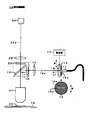
本実施形態は、請求項1〜請求項3,請求項5に対応する。ここでは、図1に示すように、標本20の蛍光観察に用いられる蛍光顕微鏡10に組み込まれ、標本20を照明する落射照明装置(11〜17)の例を説明する。
【0013】
蛍光顕微鏡10には、蛍光観察用の落射照明装置(11〜17)の他に、観察系(21〜24)が設けられている。標本20は、例えば2種類の蛍光物質で標識された生物標本(DNAや蛋白質など)であり、ステージ18上に載置されている。そして、標本20は、落射照明装置(11〜17)によって照明されると、四方八方に2種類の蛍光を発生する(詳細は後述する)。
【0014】
まず初めに、蛍光顕微鏡10の観察系(21〜24)について簡単に説明し、その後で、落射照明装置(11〜17)について詳しく説明する。
観察系(21〜24)は、光軸20aに沿って標本20側から順に、無限遠系の対物レンズ21と、蛍光フィルタ22と、第2対物レンズとして機能する結像レンズ23と、カメラ24とが配置された構成となっている。蛍光フィルタ22は、標本20から発生する2種類の蛍光の波長域を透過する特性の波長選択フィルタである。
【0015】
標本20の蛍光観察時、標本20から発生した2種類の蛍光は、対物レンズ21と後述のビームスプリッタ16と蛍光フィルタ22と結像レンズ23を介してカメラ24の撮影面に集光される。
このとき、カメラ24の撮影面には、対物レンズ21と結像レンズ23の作用によって、2種類の蛍光に基づく標本20の蛍光像が形成される。撮影面の蛍光像は、カメラ24によって撮影され、標本20の蛍光画像として取り込まれる。対物レンズ21および結像レンズ23は、請求項の「結像光学系」に対応する。
【0016】
次に、本実施形態の落射照明装置(11〜17)について説明する。
落射照明装置(11〜17)は、光軸10aに沿って順に、光源11と、開口絞り12と、スペクトル可変フィルタ13と、リレーレンズ14と、励起フィルタ15と、ビームスプリッタ16とが配置され、かつ、スペクトル可変フィルタ13に駆動部17が接続された構成となっている。
【0017】
また、落射照明装置(11〜17)は、光軸10aが観察系(21〜24)の光軸20aに対して直交する向きで、観察系(21〜24)の対物レンズ21と蛍光フィルタ22との間に組み込まれる。このとき、光軸20a上には、落射照明装置(11〜17)のビームスプリッタ16が配置される。
標本20の蛍光観察時、光源11からの照明光は、概略、開口絞り12とスペクトル可変フィルタ13とリレーレンズ14と励起フィルタ15を透過し、ビームスプリッタ16で反射して、対物レンズ21を介して標本20上に導かれる。
【0018】
さらに、本実施形態の落射照明装置(11〜17)では、対物レンズ21の瞳面に共役な基準面がリレーレンズ14によって規定され、この基準面の近傍に、光源11と開口絞り12とスペクトル可変フィルタ13とが近接して配置されている。なお、対物レンズ21の瞳面は、入射瞳面または後側焦点面とも言う。リレーレンズ14は、請求項の「照明光学系」に対応する。
【0019】
光源11は、例えば光ガイドに導かれた水銀やキセノンなどの多波長光源などであり、紫外線や可視光線などの照明光を対物レンズ21側の開口絞り12に向けて射出する。開口絞り12は、リレーレンズ14の光路中に固定的に配置された光学素子である。この開口絞り12には、落射照明装置(11〜17)の光軸10a上に細長いスリット形状(長方形)の開口12aが設けられている。開口12aの長手方向は、紙面に垂直である。
【0020】
このため、光源11からの照明光は、開口絞り12の開口12aを通過することにより、上記した基準面(対物レンズ21の瞳面に共役な面)の近傍において、開口12aに応じた所定の断面となる。この断面は開口12aと同形(相似形)である。なお、光源11は、請求項の「落射照明光源」に対応する。開口絞り12は「開口絞り部材」に対応する。
【0021】
開口絞り12の開口12aを通過した照明光は、次に、スペクトル可変フィルタ13に入射する。このとき、スペクトル可変フィルタ13の開口絞り12側の面には、開口絞り12の開口12aの像(以下「スリット像」という)が形成される。開口絞り12とスペクトル可変フィルタ13が互いに十分近接しているため、スペクトル可変フィルタ13上のスリット像は開口12aと同形(相似形)であると考えられる。
【0022】
本実施形態の落射照明装置(11〜17)では、スペクトル可変フィルタ13に駆動部17が接続され、この駆動部17を手動操作することにより、スペクトル可変フィルタ13を一方向(A)に沿ってスライドさせることができるようになっている。一方向(A)は、光軸10aの方向とスリット像の長手方向との双方に垂直な方向であり、照明光の光路に交差している。駆動部17は、請求項の「調整手段」に対応する。
【0023】
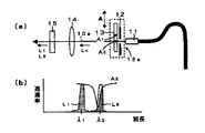
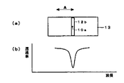
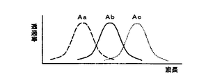
駆動部17を操作してスペクトル可変フィルタ13を一方向(A)にスライドさせると、開口絞り12からの照明光がスペクトル可変フィルタ13に入射する位置が一方向(A)に沿って相対的に変化する。図2(a)〜(c)は、開口絞り12とスペクトル可変フィルタ13を光軸10aの方向から見た図である。そして、図2(a)〜(c)に示すように、スペクトル可変フィルタ13上のスリット像12bの位置も一方向(A)に沿って相対的に変化することになる。
【0024】
さて、スペクトル可変フィルタ13は、スリット像12bを形成する照明光のスペクトルを調整するために設けられた光学素子であり、スペクトル調整後の照明光をリレーレンズ14側へ透過させる。つまり、スペクトル可変フィルタ13は、照明光の光路中に配置されている。
また、このスペクトル可変フィルタ13は、ガラス基板の一方の面(開口絞り12側の面)にコーティングを付けることにより作製された干渉フィルタである。スペクトル可変フィルタ13のコーティング領域は、一方向(A)に関して開口絞り12の開口12a(つまり上記のスリット像12b)より大きく確保されている。コーティングの厚さは、一方向(A)に沿って徐々に変化させてある。
【0025】
さらに、スペクトル可変フィルタ13は、図2(d)に示すように、特定の狭波長域を吸収または反射により遮断して、残りの波長域を透過するノッチ状の分光特性を有すると共に、その特定の狭波長域がコーティング領域内で一方向(A)に沿って連続的に変化するように構成されている。つまり、スペクトル可変フィルタ13の分光特性は、一方向(A)に沿って連続的に変化する。
【0026】
図2(d)の“Aa”〜“Ac”は、各々、図2(a)〜(c)に示すスペクトル可変フィルタ13の位置Aa〜Acにおける分光特性を例示したものである。図2(a)〜(c)と図2(d)との対応から分かるように、スペクトル可変フィルタ13の特定の狭波長域は、スペクトル可変フィルタ13の一端側から他端側に向けて波長が徐々に長くなるような連続変化を示している。
【0027】
スペクトル可変フィルタ13における特定の狭波長域の連続変化の幅は、例えば、短波長(例えば350nm)から長波長(例えば650nm)までの広範囲にわたっている。スペクトル可変フィルタ13は、請求項の「フィルタ部材」に対応する。
【0028】
したがって、上述のようにしてスペクトル可変フィルタ13を一方向(A)にスライドさせると、スリット像12bがスペクトル可変フィルタ13の位置Aaに形成される図2(a)の状態では、図2(d)の“Aa”の分光特性に応じたスペクトルを持つ照明光L0がスペクトル可変フィルタ13から透過することになる。同様に、スリット像12bがスペクトル可変フィルタ13の位置Ab,Acに形成される図2(b),(c)の状態では、図2(d)の“Ab”,“Ac”の分光特性に応じたスペクトルを持つ照明光L0がスペクトル可変フィルタ13から透過することになる。
【0029】
つまり、スペクトル可変フィルタ13を一方向(A)にスライドさせることにより、スペクトル可変フィルタ13の分光特性(特定の狭波長域)の連続的な分布に応じて、スペクトル可変フィルタ13を透過する照明光L0のスペクトルを容易に調整(選択)することができる。なお、スペクトル可変フィルタ13を透過する照明光L0のスペクトル幅は、開口絞り12の開口12aの幅に応じて決まっている。
【0030】
上記のスペクトル可変フィルタ13を透過してスペクトル調整された照明光L0は、次に、リレーレンズ14(図1)に入射する。既に説明したように、リレーレンズ14は、対物レンズ21の瞳面に共役な基準面を規定する光学系である。このため、その基準面の近傍に配置されたスペクトル可変フィルタ13からの照明光L0は、リレーレンズ14の作用によって対物レンズ21の瞳面に集光される。
【0031】
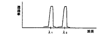
ただし、リレーレンズ14を透過した照明光は、観察系(21〜24)の光軸20a上に導かれる前に、つまり、落射照明装置(11〜17)の光軸10a上を進行している間に、励起フィルタ15を透過する。この励起フィルタ15は、図3に示すように、予め定められた2つの異なる狭波長域λ1,λ2で照明光を透過するフィルタである。
【0032】
ちなみに、励起フィルタ15の2つの狭波長域λ1,λ2のうち一方は、標本20の中の一方の蛍光物質を励起するために適切な狭波長域であり、2つの狭波長域λ1,λ2のうち他方は、標本20の中の他方の蛍光物質を励起するために適切な狭波長域である。
励起フィルタ15に入射する照明光のスペクトルは、スペクトル可変フィルタ13を透過した照明光L0のスペクトルと同じである。つまり、リレーレンズ14によって照明光のスペクトルが変化することはない。このため、励起フィルタ15は、照明光L0の波長域(図2(d)参照)のうち、2つの狭波長域λ1,λ2(図3)のみを同時に抽出する。
【0033】
したがって、励起フィルタ15を透過した照明光は、異なる狭波長域λ1,λ2の2つの照明光L1,L2を含むものとなる。この2つの照明光L1,L2は、励起フィルタ15に入射する照明光L0の一部である。そして、2つの照明光L1,L2が対物レンズ21の瞳面に集光され、対物レンズ21を通過した後、標本20に照射される。
【0034】
標本20の中では、一方の蛍光物質が例えば狭波長域λ1の照明光L1によって励起され、自身の蛍光発生効率(照明光の光量に対する蛍光の光量の比率)に応じた光量の蛍光を発生する。同様に、他方の蛍光物質は例えば狭波長域λ2の照明光L2によって励起され、自身の蛍光発生効率に応じた光量の蛍光を発生する。
これら2種類の蛍光は、上記した観察系(21〜24)のカメラ24に導かれ、カメラ24によって2種類の蛍光に基づく標本20の蛍光像が撮影され、標本20の蛍光画像として取り込まれる。このとき、2種類の蛍光の光量が異なってしまうと、標本20の蛍光画像には明るい像と暗い像が混在することになり、非常に観察し辛い。
【0035】
次に、標本20の各々の蛍光物質から発生する蛍光の光量を等しくするために、本実施形態の落射照明装置(11〜17)を用い、標本20に照射される2つの照明光L1,L2の光量を調整する方法について説明する。
【0036】
上述したように、本実施形態の落射照明装置(11〜17)では、スペクトル可変フィルタ13を一方向(A)にスライドさせることにより、スペクトル可変フィルタ13を透過する照明光L0のスペクトルを容易に調整できる。
このため、例えば図4(a)に示すように、開口12aのスリット像がスペクトル可変フィルタ13の位置A1に形成される状態のとき、図4(b)の“A1”の分光特性に応じたスペクトルを持つ照明光L0がスペクトル可変フィルタ13から透過することになる。
【0037】
図4(b)の“A1”の分光特性とは、その狭波長域が、励起フィルタ15の一方の狭波長域λ1と少し重なり、他方の狭波長域λ2とは重ならないような特性である。したがって、励起フィルタ15を透過する2つの照明光のうち、狭波長域λ1の照明光L1の光量は、図4(b)の斜線ハッチング部に示すように減量され、狭波長域λ2の照明光L2の光量は、点ハッチング部に示すように最大光量のまま保たれる。
【0038】
このような設定は、狭波長域λ1の照明光L1によって励起可能な一方の蛍光物質の蛍光発生効率と比較して、狭波長域λ2の照明光L2によって励起可能な他方の蛍光物質の蛍光発生効率が低い場合に有効である。
また、例えば図5(a)に示すように、開口12aのスリット像がスペクトル可変フィルタ13の位置A2に形成される状態のとき、図5(b)の“A2”の分光特性に応じたスペクトルを持つ照明光L0がスペクトル可変フィルタ13から透過することになる。
【0039】
図5(b)の“A2”の分光特性とは、その狭波長域が、励起フィルタ15の他方の狭波長域λ2と少し重なり、他方の狭波長域λ1とは重ならないような特性である。したがって、励起フィルタ15を透過する2つの照明光のうち、狭波長域λ2の照明光L2の光量は、図5(b)の斜線ハッチング部に示すように減量され、狭波長域λ1の照明光L1の光量は、点ハッチング部に示すように最大光量のまま保たれる。
【0040】
このような設定は、狭波長域λ1の照明光L1によって励起可能な一方の蛍光物質の蛍光発生効率と比較して、狭波長域λ2の照明光L2によって励起可能な他方の蛍光物質の蛍光発生効率が高い場合に有効である。
本実施形態の落射照明装置(11〜17)では、スペクトル可変フィルタ13を一方向(A)にスライドさせるだけで、標本20に照射される2つの照明光L1,L2の光量バランスを容易に調整することができ、標本20の各々の蛍光物質から発生する蛍光の光量を等しくできる。
【0041】
その結果、カメラ24で取り込まれる標本20の蛍光画像には、標本20の異なる部位に関する2種類の蛍光像が共に適切な明るさで混在することになり、良好な蛍光観察が可能となる。
さらに、本実施形態の落射照明装置(11〜17)では、スペクトル可変フィルタ13における特定の狭波長域の連続変化の幅が広範囲にわたっている(例えば350nm〜650nm)ため、スペクトル可変フィルタ13を一方向(A)にスライドさせるだけで、照明光L1,L2の光量バランスを広い波長域で連続的に調整することができる。
【0042】
また、励起フィルタ15を異なる狭波長域のものに交換したときでも、スペクトル可変フィルタ13を交換する必要がない。つまり、スペクトル可変フィルタ13を交換しなくても、任意の蛍光物質の組み合わせにも柔軟に対応することができ、照明光L1,L2の光量バランスを連続的に調整できる。その結果、作業が簡単化すると共に安価に構成でき、汎用性が向上する。
【0043】
さらに、本実施形態の落射照明装置(11〜17)では、スペクトル可変フィルタ13を対物レンズ21の瞳面に共役な基準面の近傍に配置するため、標本20の視野における光学特性の劣化(照明ムラなど)が生じることはない。したがって、照明光L1,L2の光量バランスを連続的に調整した場合でも、高精度な蛍光観察が可能となる。
【0044】
なお、上記した実施形態は、開口絞り12の開口12aの幅(一方向(A)に関する大きさ)が一定である例を説明したが、図6(a),図7(a)に示すように、光軸10aを中心として開口12aの幅を変化させることもできる。このような変化も、上記の駆動部17(図1)を用いた手動操作により簡単に行うことができる。
【0045】
この場合、図6(b),図7(b)に示すように、開口12aの幅に応じて、スペクトル可変フィルタ13を透過する照明光L0のスペクトル幅を容易に調整することができる。開口12aの幅が広いほど、照明光L0のスペクトル幅も広い。そして、標本20に照射される2つの照明光L1,L2の光量を同時に強くしたり弱くしたりすることができる。
【0046】
また、上記した実施形態では、対物レンズ21の瞳面に共役な基準面の近傍に1枚のスペクトル可変フィルタ13を設けたが、図8に示すように、励起フィルタ35が3つの異なる狭波長域λ1,λ2,λ3で照明光を透過するように構成されている場合には、2枚のスペクトル可変フィルタ13(1),13(2)を設けることもできる。スペクトル可変フィルタ13(1),13(2)の分光特性は、上記したスペクトル可変フィルタ13と同じである(図2参照)。スペクトル可変フィルタ13(1),13(2)は、駆動部17によって独立にスライド可能である。
【0047】
この場合、スペクトル可変フィルタ13(1),13(2)を一方向(A)に独立にスライドさせることにより、例えば、開口絞り12の開口12aのスリット像が、スペクトル可変フィルタ13(1)の位置A1とスペクトル可変フィルタ13(2)の位置A2に形成されるような設定とすることができる。
このとき、図8(b)に示すように、スペクトル可変フィルタ13(1)の“A1”の分光特性(励起フィルタ15の狭波長域λ2と少し重なる特性)と、スペクトル可変フィルタ13(2)の“A2”の分光特性(励起フィルタ15の狭波長域λ3と少し重なる特性)とに応じて、次のような照明状態を得ることができる。
【0048】
つまり、狭波長域λ2,λ3の照明光L2,L3の光量を、図8(b)の斜線ハッチング部に示すように減量し、狭波長域λ1の照明光L1の光量を、点ハッチング部に示すように最大光量のまま保つことができる。このような構成および設定は、標本20が3つの蛍光物質で標識され、狭波長域λ1の照明光L1によって励起可能な蛍光物質の蛍光発生効率と比較して、狭波長域λ2,λ3の照明光L2,L3によって励起可能な蛍光物質の蛍光発生効率が高い場合に有効である。
【0049】
また、4つ以上の蛍光物質で標識された標本20の蛍光観察を行う場合にも、本発明は適用できる。この場合には上記と同様に、スペクトル可変フィルタの数を増やせばよい。
さらに、上記した実施形態では、特定の狭波長域を遮断して残りの波長域を透過するノッチ状の分光特性を有するスペクトル可変フィルタの例を説明したが、図9に示すように、特定の狭波長域を透過して残りの波長域を遮断するバリア状の分光特性を有するスペクトル可変フィルタ33(図10,図11)を用いることもできる。
【0050】
このようなバリアフィルタを用いる場合にも、上記のノッチフィルタを用いた場合と同様、スペクトル可変フィルタ33を一方向(A)にスライドさせるだけで、2つの照明光L1,L2の光量バランスを容易に調整することができ、標本20の各々の蛍光物質から発生する蛍光の光量を等しくできる。
さらに、スペクトル可変フィルタ33における特定の狭波長域の連続変化の幅が広範囲にわたっている(例えば350nm〜650nm)ため、スペクトル可変フィルタ33を一方向(A)にスライドさせるだけで、照明光L1,L2の光量バランスを広い波長域で連続的に調整することができる。
【0051】
また、励起フィルタ15を異なる狭波長域のものに交換したときでも、スペクトル可変フィルタ33を交換する必要がない。つまり、スペクトル可変フィルタ33を交換しなくても、任意の蛍光物質の組み合わせにも柔軟に対応することができ、照明光L1,L2の光量バランスを連続的に調整できる。その結果、作業が簡単化すると共に安価に構成でき、汎用性が向上する。
【0052】
さらに、スペクトル可変フィルタ33を対物レンズ21の瞳面に共役な基準面の近傍に配置するため、標本20の視野における照明ムラなどが生じることはない。したがって、照明光L1,L2の光量バランスを連続的に調整した場合でも、高精度な蛍光観察が可能となる。
また、スペクトル可変フィルタ33を用いた場合であっも、図12(a),図13(a)に示すように、光軸10aを中心として開口12aの幅を変化させることで、図12(b),図13(b)に示すように、スペクトル可変フィルタ33を透過する照明光L0のスペクトル幅を容易に調整することができる。開口12aの幅が広いほど、照明光L0のスペクトル幅も広い。そして、標本20に照射される2つの照明光L1,L2の光量を同時に強くしたり弱くしたりすることができる。
【0053】
さらに、上記した実施形態では、1枚のスペクトル可変フィルタ33でバリア状の分光特性(図9参照)を達成する例を説明したが、図14(a)に示すように特定の臨界波長から長波側を透過するスペクトル可変フィルタ33(1)と、図14(b)に示すように特定の臨界波長から短波側を透過するスペクトル可変フィルタ33(2)とを組み合わせることもできる。
【0054】
なお、スペクトル可変フィルタ33(1),(2)の臨界波長は、各々、一方向(A)に沿って連続的に変化するように構成されている。また、スペクトル可変フィルタ33(1),(2)は、駆動部17によって独立にスライド可能である。この場合にも、上記した1枚のバリアフィルタ(スペクトル可変フィルタ33)を用いた場合と同様の効果を得ることができる。
【0055】
さらに、上記した実施形態では、対物レンズ21の瞳面に共役な基準面の近傍に光源11と開口絞り12を配置したが、このような光源手段(11,12)に代えて、光ガイドを用いることもできる。この場合、光ガイドの出射端面をスペクトル可変フィルタの近傍に配置することが好ましい。また、光源手段(11,12)に代えて、水銀ランプと集光レンズを用いることもできる。この場合、集光レンズによってスペクトル可変フィルタの近傍にアーク像を形成することが好ましい。
【0056】
また、上記した実施形態では、光源11,開口絞り12,スペクトル可変フィルタ13の順に配置する例を説明したが、開口絞り12とスペクトル可変フィルタ13の位置関係は逆でもよい。光源手段(11,12)に代えて水銀ランプと集光レンズを用いる場合には、開口絞り12を省略することもできる。
さらに、上記した実施形態では、開口絞り12を固定的に配置すると共にスペクトル可変フィルタ13を一方向(A)に沿ってスライドさせる構成例を説明したが、本発明はこれに限らない。スペクトル可変フィルタ13を固定的に配置すると共に開口絞り12を一方向(A)に沿ってスライドさせてもよいし、スペクトル可変フィルタ13と開口絞り12とを一方向(A)に沿って相対的にスライド(移動)させてもよい。
【0057】
また、上記した実施形態では、落射照明装置(11〜17)と観察系(21〜24)とが交差する箇所にビームスプリッタ16を配置したが、これに代えてダイクロイックミラーを配置しても良い。ダイクロイックミラーは、励起フィルタ15,35を透過した複数の狭波長域の照明光を反射可能で、標本20から発生した複数の蛍光を透過可能な分光特性を有する。
【0058】
さらに、上記した実施形態では、蛍光顕微鏡10に落射照明装置(11〜17)を組み込む例で説明したが、落射照明装置(11〜17)は、蛍光顕微鏡だけでなく、他の蛍光測定装置に組み込むこともできる。
【0059】
【発明の効果】
以上説明したように、本発明によれば、標本に対する複数の照明光の光量を広い波長域で連続的に調整することができると共に安価に構成することもできる。
【図面の簡単な説明】
【図1】蛍光顕微鏡10および落射照明装置(11〜17)の全体構成図である。
【図2】スペクトル可変フィルタ13の分光特性(ノッチ状)を説明する図である。
【図3】励起フィルタ15の分光特性を説明する図である。
【図4】落射照明装置(11〜17)による光量バランスの調整方法を説明する図である。
【図5】落射照明装置(11〜17)による光量バランスの調整方法を説明する図である。
【図6】開口絞り12の開口12aの幅とスペクトル可変フィルタ13の分光特性との関係を説明する図である。
【図7】開口絞り12の開口12aの幅とスペクトル可変フィルタ13の分光特性との関係を説明する図である。
【図8】2枚のスペクトル可変フィルタを設けた落射照明装置を説明する図である。
【図9】他のスペクトル可変フィルタの分光特性(バリア状)を説明する図である。
【図10】ノッチフィルタを用いた落射照明装置による光量バランスの調整方法を説明する図である。
【図11】ノッチフィルタ(33)を用いた落射照明装置による光量バランスの調整方法を説明する図である。
【図12】開口絞り12の開口12aの幅とスペクトル可変フィルタ33の分光特性との関係を説明する図である。
【図13】開口絞り12の開口12aの幅とスペクトル可変フィルタ33の分光特性との関係を説明する図である。
【図14】他のスペクトル可変フィルタの分光特性(臨界波長型)を説明する図である。
【図15】図14の分光特性を有するスペクトル可変フィルタを用いた場合の光量バランスの調整方法を説明する図である。
【符号の説明】
10 蛍光顕微鏡
11 光源
12 開口絞り
13,33 スペクトル可変フィルタ
14 リレーレンズ
15,35 励起フィルタ
16 ビームスプリッタ
17 駆動部
18 ステージ
20 標本
21 対物レンズ
22 蛍光フィルタ
23 結像レンズ
24 カメラ[0001]
TECHNICAL FIELD OF THE INVENTION
The present invention relates to an epi-illumination device for fluorescence observation that illuminates a specimen labeled with a plurality of fluorescent substances, and a fluorescence microscope including the same.
[0002]
[Prior art]
Conventionally, fluorescence observation of a specimen labeled with a plurality of fluorescent substances has been performed using a fluorescence microscope or the like. Each of the plurality of fluorescent substances is attached to a different site in the specimen. For this reason, by taking in the fluorescence image of the specimen based on the fluorescence generated from each fluorescent substance, it is possible to observe a plurality of different parts of the specimen labeled with a plurality of fluorescent substances at the same time.
[0003]
By the way, in order to generate fluorescence from each fluorescent substance in a specimen, each fluorescent substance must be excited with illumination light in an appropriate narrow wavelength range, and an appropriate amount of illumination light for each fluorescent substance Narrow wavelength regions are generally different. For this reason, at the time of fluorescence observation of the sample, the sample labeled with a plurality of fluorescent substances is irradiated with a plurality of illumination lights having different narrow wavelength ranges. Such a plurality of illumination lights are usually generated by an excitation filter that transmits light in a plurality of predetermined narrow wavelength bands.
[0004]
In addition, since each fluorescent substance generally has a different fluorescence generation efficiency (ratio of the amount of fluorescence to the amount of illumination light), when the amount of illumination light (different in a narrow wavelength range) applied to the sample is equal to each other, In this case, the amount of fluorescent light generated from each fluorescent substance is different.
[0005]
Then, in the fluorescent image of the specimen taken in this situation, the site of attachment of the fluorescent substance having high fluorescence generation efficiency appears as a bright image, and the site of attachment of the fluorescent material having low fluorescence generation efficiency appears as a dark image. As described above, when a bright image and a dark image are mixed in the fluorescent image of the specimen, it is very difficult to observe any part of the specimen.
Therefore, in order to equalize the amount of fluorescence generated from each fluorescent substance of the sample, a method of adjusting the amounts of a plurality of illumination lights applied to the sample has been proposed. For example, Japanese Patent No. 3093009 describes a method in which an interference filter is disposed between a light source and an excitation filter, and the incident angle of an incident light beam incident on the interference filter is changed to adjust the light amounts of a plurality of illumination lights. ing. The illumination light transmitted through the interference filter becomes a plurality of illumination lights having different narrow wavelength ranges after passing through the excitation filter.
[0006]
In this adjustment method, the spectrum of the illumination light transmitted through the interference filter shifts according to the rotation angle of the interference filter, and the spectrum of the illumination light incident on the excitation filter also shifts. The amount of light can be adjusted.
In addition, a plurality of interference filters having different transmission wavelength ranges are prepared in advance, and any one of the interference filters is selectively placed in the optical path of the illumination light (the light source and the excitation filter) according to the narrow wavelength range of the excitation filter. A method of changing the spectrum of the illuminating light by arranging the illuminating light at a distance between them and adjusting the light amounts of the plurality of illuminating lights with respect to the sample has also been proposed.
[0007]
[Problems to be solved by the invention]
However, the method of rotating the interference filter has a problem that the wavelength range in which the light amounts of the plurality of illumination lights can be adjusted is narrow because the shift range of the spectrum of the illumination light transmitted through the interference filter is small. In addition, every time the excitation filter is replaced with one having a different narrow wavelength band, it must be replaced with an interference filter having a shift range adapted to the narrow wavelength band of the excitation filter, which complicates the operation and reduces the cost. Will be high.
[0008]
Further, in the above-described method of replacing the interference filters, the light amounts of the plurality of illumination lights cannot be continuously adjusted, and a plurality of interference filters are required for one excitation filter, which increases the cost.
An object of the present invention is to provide an epi-illumination device for fluorescence observation, which can continuously adjust the light amounts of a plurality of illumination lights to a sample in a wide wavelength range and can be configured at low cost, and to provide a fluorescence microscope including the same. It is in.
[0009]
[Means for Solving the Problems]
The invention according to
[0010]
According to a second aspect of the present invention, in the epi-illumination apparatus for fluorescence observation according to the first aspect, the filter member has a notch-like spectrum capable of cutting off a specific narrow wavelength range and extracting a remaining wavelength range. In addition to having the characteristic, the specific narrow wavelength range changes continuously along the one direction.
According to a third aspect of the present invention, in the epi-illumination device for fluorescence observation according to the first or second aspect, the aperture stop member is fixedly arranged, and the adjusting means is arranged along the one direction. The spectrum is adjusted by moving the filter member.
[0011]
According to a fourth aspect of the present invention, in the epi-illumination device for fluorescence observation according to any one of the first to third aspects, the opening of the aperture stop member has a variable size in the one direction. The adjusting means adjusts the spectrum by changing the size of the aperture.
The invention according to claim 5 is an epi-illumination device for fluorescence observation according to any one of
[0012]
BEST MODE FOR CARRYING OUT THE INVENTION
Hereinafter, embodiments of the present invention will be described in detail with reference to the drawings.
This embodiment corresponds to
[0013]
The
[0014]
First, the observation system (21 to 24) of the
The observation system (21 to 24) includes, in order from the
[0015]
When observing the fluorescence of the
At this time, a fluorescent image of the
[0016]
Next, the epi-illumination devices (11 to 17) of the present embodiment will be described.
In the epi-illumination device (11 to 17), a
[0017]
The epi-illumination device (11-17) has an optical axis 10a in a direction orthogonal to an optical axis 20a of the observation system (21-24), and the
At the time of fluorescence observation of the
[0018]
Further, in the epi-illumination device (11 to 17) of the present embodiment, a reference plane conjugate to the pupil plane of the
[0019]
The
[0020]
For this reason, the illumination light from the
[0021]
The illumination light having passed through the aperture 12a of the
[0022]
In the epi-illumination device (11 to 17) of the present embodiment, the driving
[0023]
When the
[0024]
Now, the spectrum
The
[0025]
Further, as shown in FIG. 2D, the spectrum
[0026]
“Aa” to “Ac” in FIG. 2D exemplify the spectral characteristics at the positions Aa to Ac of the
[0027]
The width of the continuous change in the specific narrow wavelength range in the spectrum
[0028]
Therefore, when the spectrum
[0029]
That is, by sliding the spectrum
[0030]
Illumination light L whose spectrum has been adjusted by passing through the above-mentioned spectrum
[0031]
However, the illumination light transmitted through the
[0032]
By the way, the two narrow wavelength ranges λ of the
The spectrum of the illumination light incident on the
[0033]
Therefore, the illumination light transmitted through the
[0034]
In the
These two types of fluorescent light are guided to the
[0035]
Next, in order to equalize the amounts of fluorescent light generated from the respective fluorescent substances of the
[0036]
As described above, in the epi-illumination device (11 to 17) of the present embodiment, the illumination light L transmitted through the spectrum
Therefore, for example, as shown in FIG. 4A, the slit image of the aperture 12a is positioned at the position A of the spectrum
[0037]
“A” in FIG. 1 The spectral characteristic “” indicates that the narrow wavelength range is one of the narrow wavelength ranges λ of the
[0038]
Such setting is performed in a narrow wavelength range λ 1 Illumination light L 1 Compared to the fluorescence generation efficiency of one fluorescent substance that can be excited by 2 Illumination light L 2 This is effective when the fluorescence generation efficiency of the other fluorescent substance that can be excited by light is low.
Also, as shown in FIG. 5A, for example, the slit image of the aperture 12a is positioned at the position A of the spectrum
[0039]
“A” in FIG. 2 The spectral characteristic “” indicates that the narrow wavelength range is the other narrow wavelength range λ of the
[0040]
Such setting is performed in a narrow wavelength range λ 1 Illumination light L 1 Compared to the fluorescence generation efficiency of one fluorescent substance that can be excited by 2 Illumination light L 2 This is effective when the fluorescence generation efficiency of the other fluorescent substance that can be excited by the light is high.
In the epi-illumination devices (11 to 17) of the present embodiment, the two illumination light L illuminated on the
[0041]
As a result, in the fluorescence image of the
Furthermore, in the epi-illumination device (11 to 17) according to the present embodiment, the continuous variable width of the specific narrow wavelength range in the spectrum
[0042]
Further, even when the
[0043]
Further, in the epi-illumination device (11 to 17) of the present embodiment, since the spectrum
[0044]
In the above-described embodiment, an example in which the width (the size in one direction (A)) of the aperture 12a of the
[0045]
In this case, as shown in FIG. 6B and FIG. 7B, the illumination light L transmitted through the spectrum
[0046]
In the above-described embodiment, one
[0047]
In this case, by independently sliding the spectrum variable filters 13 (1) and 13 (2) in one direction (A), for example, the slit image of the aperture 12a of the
At this time, as shown in FIG. 8B, “A” of the spectrum variable filter 13 (1) 1 (The narrow wavelength range λ of the excitation filter 15) 2 And the “A” of the spectrum tunable filter 13 (2). 2 (The narrow wavelength range λ of the excitation filter 15) 3 The following illumination state can be obtained in accordance with the characteristic that slightly overlaps with the above).
[0048]
That is, the narrow wavelength range λ 2 , Λ 3 Illumination light L 2 , L 3 Is reduced as shown by the hatched portion in FIG. 1 Illumination light L 1 Can be maintained at the maximum light amount as shown by the hatched portion. With such a configuration and setting, the
[0049]
The present invention is also applicable to the case where fluorescence observation of the
Furthermore, in the above-described embodiment, an example of a spectrum variable filter having a notch-like spectral characteristic that blocks a specific narrow wavelength band and transmits the remaining wavelength band has been described. However, as illustrated in FIG. It is also possible to use a spectrum variable filter 33 (FIGS. 10 and 11) having a barrier-like spectral characteristic that transmits a narrow wavelength range and blocks the remaining wavelength range.
[0050]
In the case of using such a barrier filter, as in the case of using the above-described notch filter, the two illumination lights L can be obtained simply by sliding the
Further, since the width of the continuous change in the specific narrow wavelength range in the spectrum
[0051]
Further, even when the
[0052]
Further, since the spectrum
Also, even when the spectrum
[0053]
Further, in the above-described embodiment, an example has been described in which a single spectral
[0054]
The critical wavelengths of the spectrum variable filters 33 (1) and (2) are configured to change continuously along one direction (A). Further, the spectrum variable filters 33 (1) and (2) can be independently slid by the
[0055]
Further, in the above-described embodiment, the
[0056]
Further, in the above-described embodiment, an example has been described in which the
Furthermore, in the above-described embodiment, the configuration example in which the
[0057]
Further, in the above-described embodiment, the
[0058]
Furthermore, in the above-described embodiment, an example in which the epi-illumination devices (11 to 17) are incorporated in the
[0059]
【The invention's effect】
As described above, according to the present invention, it is possible to continuously adjust the light amounts of a plurality of illumination lights with respect to a sample in a wide wavelength range, and it is possible to configure the apparatus at low cost.
[Brief description of the drawings]
FIG. 1 is an overall configuration diagram of a
FIG. 2 is a diagram illustrating spectral characteristics (notch shape) of a variable spectrum filter.
FIG. 3 is a diagram illustrating spectral characteristics of an
FIG. 4 is a diagram illustrating a method of adjusting the light amount balance by the epi-illumination devices (11 to 17).
FIG. 5 is a diagram illustrating a method of adjusting the light amount balance by the epi-illumination devices (11 to 17).
FIG. 6 is a diagram for explaining the relationship between the width of the aperture 12a of the
FIG. 7 is a diagram illustrating the relationship between the width of an aperture 12a of an
FIG. 8 is a diagram illustrating an epi-illumination device provided with two spectrum variable filters.
FIG. 9 is a diagram illustrating spectral characteristics (barrier shape) of another spectrum variable filter.
FIG. 10 is a diagram illustrating a method of adjusting a light amount balance by an epi-illumination device using a notch filter.
FIG. 11 is a diagram illustrating a method of adjusting a light amount balance by an epi-illumination device using a notch filter (33).
FIG. 12 is a diagram for explaining the relationship between the width of the aperture 12a of the
FIG. 13 is a diagram illustrating the relationship between the width of the aperture 12a of the
FIG. 14 is a diagram illustrating spectral characteristics (critical wavelength type) of another spectrum variable filter.
FIG. 15 is a diagram illustrating a method of adjusting the light amount balance when the spectrum variable filter having the spectral characteristics of FIG. 14 is used.
[Explanation of symbols]
10 Fluorescence microscope
11 Light source
12 Aperture stop
13,33 Spectrum variable filter
14 relay lens
15,35 Excitation filter
16 Beam splitter
17 Driver
18 stages
20 specimens
21 Objective lens
22 Fluorescent filter
23 Imaging lens
24 Camera
Claims (5)
前記照明光学系の光路中で対物レンズの瞳面と略共役な面に配置された開口絞り部材と、
前記開口絞り部材に近接して配置され、前記光路に直交する一方向に沿って分光特性が連続的に変化するフィルタ部材と、
前記一方向に沿って前記開口絞り部材と前記フィルタ部材とを相対移動させることにより、前記開口絞り部材および前記フィルタ部材を通過した後の光のスペクトルを調整する調整手段とを備えた
ことを特徴とする蛍光観察用の落射照明装置。Epi-illumination light source, an excitation filter that extracts light in a plurality of narrow wavelength ranges, and an epi-illumination device for fluorescence observation including an illumination optical system that guides light from the epi-illumination light source to the excitation filter,
An aperture stop member arranged on a plane substantially conjugate with a pupil plane of the objective lens in an optical path of the illumination optical system,
A filter member that is disposed close to the aperture stop member and has a spectral characteristic that continuously changes along one direction orthogonal to the optical path;
Adjusting means for adjusting the spectrum of light after passing through the aperture stop member and the filter member by relatively moving the aperture stop member and the filter member along the one direction. Epi-illumination device for fluorescence observation.
前記フィルタ部材は、特定の狭波長域を遮断して残りの波長域を抽出可能なノッチ状の分光特性を有すると共に、前記特定の狭波長域が前記一方向に沿って連続的に変化する
ことを特徴とする蛍光観察用の落射照明装置。The epi-illumination device for fluorescence observation according to claim 1,
The filter member has a notch-like spectral characteristic capable of cutting out a specific narrow wavelength range and extracting a remaining wavelength range, and the specific narrow wavelength range changes continuously along the one direction. An epi-illumination device for fluorescence observation, characterized in that:
前記開口絞り部材は、固定的に配置され、
前記調整手段は、前記一方向に沿って前記フィルタ部材を移動させることにより、前記スペクトルを調整する
ことを特徴とする蛍光観察用の落射照明装置。The epi-illumination device for fluorescence observation according to claim 1 or 2,
The aperture stop member is fixedly arranged,
The epi-illumination device for fluorescence observation, wherein the adjusting means adjusts the spectrum by moving the filter member along the one direction.
前記開口絞り部材の開口は、前記一方向に関する大きさが可変であり、
前記調整手段は、前記開口の前記大きさを変化させることにより、前記スペクトルを調整する
ことを特徴とする蛍光観察用の落射照明装置。The epi-illumination device for fluorescence observation according to any one of claims 1 to 3,
The aperture of the aperture stop member has a variable size in the one direction,
The epi-illumination device for fluorescence observation, wherein the adjusting means adjusts the spectrum by changing the size of the aperture.
請求項1から請求項4の何れか1項に記載した蛍光観察用の落射照明装置と、対物レンズを含み、前記標本からの蛍光を集光して前記標本の蛍光像を形成する結像光学系とを備えた
ことを特徴とする蛍光顕微鏡。In a fluorescence microscope used for fluorescence observation of a specimen labeled with a plurality of fluorescent substances,
An imaging optics comprising the epi-illumination device for fluorescence observation according to any one of claims 1 to 4, and an objective lens, and condensing fluorescence from the sample to form a fluorescence image of the sample. A fluorescence microscope, comprising:
Priority Applications (2)
| Application Number | Priority Date | Filing Date | Title |
|---|---|---|---|
| JP2002164633A JP2004012702A (en) | 2002-06-05 | 2002-06-05 | Vertical illuminator for fluorescent observation and fluorescent microscope provided therewith |
| US10/453,660 US6906859B2 (en) | 2002-06-05 | 2003-06-04 | Epi-illumination apparatus for fluorescent observation and fluorescence microscope having the same |
Applications Claiming Priority (1)
| Application Number | Priority Date | Filing Date | Title |
|---|---|---|---|
| JP2002164633A JP2004012702A (en) | 2002-06-05 | 2002-06-05 | Vertical illuminator for fluorescent observation and fluorescent microscope provided therewith |
Publications (1)
| Publication Number | Publication Date |
|---|---|
| JP2004012702A true JP2004012702A (en) | 2004-01-15 |
Family
ID=30432722
Family Applications (1)
| Application Number | Title | Priority Date | Filing Date |
|---|---|---|---|
| JP2002164633A Pending JP2004012702A (en) | 2002-06-05 | 2002-06-05 | Vertical illuminator for fluorescent observation and fluorescent microscope provided therewith |
Country Status (1)
| Country | Link |
|---|---|
| JP (1) | JP2004012702A (en) |
Cited By (6)
| Publication number | Priority date | Publication date | Assignee | Title |
|---|---|---|---|---|
| JP2005321753A (en) * | 2004-04-05 | 2005-11-17 | Olympus Corp | Vertical illumination microscope and fluorescence filter set |
| JP2007333833A (en) * | 2006-06-13 | 2007-12-27 | Olympus Corp | Vertical illumination optical system for microscope |
| JP2012058732A (en) * | 2010-09-06 | 2012-03-22 | Leica Microsystems (Schweiz) Ag | Surgical fluorescence stereomicroscope |
| JP2012247244A (en) * | 2011-05-26 | 2012-12-13 | Fujifilm Corp | Fluorescence analysis device and fluorescence analysis method |
| JP5884021B2 (en) * | 2013-02-13 | 2016-03-15 | パナソニックIpマネジメント株式会社 | Multispectral imaging apparatus and multispectral imaging method |
| JP2018040914A (en) * | 2016-09-07 | 2018-03-15 | ウシオ電機株式会社 | Fluorescence microscope-purpose light source device and fluorescence microscope |
Citations (5)
| Publication number | Priority date | Publication date | Assignee | Title |
|---|---|---|---|---|
| JPH08320437A (en) * | 1995-05-25 | 1996-12-03 | Olympus Optical Co Ltd | Vertically illuminating fluorescent microscope |
| JPH1073768A (en) * | 1996-08-30 | 1998-03-17 | Olympus Optical Co Ltd | Illuminator for microscope |
| JPH10197799A (en) * | 1997-01-08 | 1998-07-31 | Olympus Optical Co Ltd | Optical axis deviation correcting device and scan type optical microscope |
| JPH11211986A (en) * | 1998-01-23 | 1999-08-06 | Olympus Optical Co Ltd | Fluorescence microscope device |
| JP2000098244A (en) * | 1998-09-24 | 2000-04-07 | Olympus Optical Co Ltd | Fluorescent microscope |
-
2002
- 2002-06-05 JP JP2002164633A patent/JP2004012702A/en active Pending
Patent Citations (5)
| Publication number | Priority date | Publication date | Assignee | Title |
|---|---|---|---|---|
| JPH08320437A (en) * | 1995-05-25 | 1996-12-03 | Olympus Optical Co Ltd | Vertically illuminating fluorescent microscope |
| JPH1073768A (en) * | 1996-08-30 | 1998-03-17 | Olympus Optical Co Ltd | Illuminator for microscope |
| JPH10197799A (en) * | 1997-01-08 | 1998-07-31 | Olympus Optical Co Ltd | Optical axis deviation correcting device and scan type optical microscope |
| JPH11211986A (en) * | 1998-01-23 | 1999-08-06 | Olympus Optical Co Ltd | Fluorescence microscope device |
| JP2000098244A (en) * | 1998-09-24 | 2000-04-07 | Olympus Optical Co Ltd | Fluorescent microscope |
Cited By (7)
| Publication number | Priority date | Publication date | Assignee | Title |
|---|---|---|---|---|
| JP2005321753A (en) * | 2004-04-05 | 2005-11-17 | Olympus Corp | Vertical illumination microscope and fluorescence filter set |
| JP2007333833A (en) * | 2006-06-13 | 2007-12-27 | Olympus Corp | Vertical illumination optical system for microscope |
| JP2012058732A (en) * | 2010-09-06 | 2012-03-22 | Leica Microsystems (Schweiz) Ag | Surgical fluorescence stereomicroscope |
| JP2012247244A (en) * | 2011-05-26 | 2012-12-13 | Fujifilm Corp | Fluorescence analysis device and fluorescence analysis method |
| US8658989B2 (en) | 2011-05-26 | 2014-02-25 | Fujifilm Corporation | Fluorometric assay apparatus and fluorometric assay method |
| JP5884021B2 (en) * | 2013-02-13 | 2016-03-15 | パナソニックIpマネジメント株式会社 | Multispectral imaging apparatus and multispectral imaging method |
| JP2018040914A (en) * | 2016-09-07 | 2018-03-15 | ウシオ電機株式会社 | Fluorescence microscope-purpose light source device and fluorescence microscope |
Similar Documents
| Publication | Publication Date | Title |
|---|---|---|
| US5371624A (en) | Reflected fluorescence microscope | |
| EP2315065B1 (en) | Microscope | |
| JP3526489B2 (en) | Epi-fluorescence microscope | |
| US7239384B2 (en) | Laser-scanning fluoroscopy apparatus | |
| US6906859B2 (en) | Epi-illumination apparatus for fluorescent observation and fluorescence microscope having the same | |
| US20070242335A1 (en) | Translational filter, shutter, aperture apparatus for selecting and combining filtered and unfiltered light | |
| EP1918757A1 (en) | Microscope illumination apparatus | |
| JP2000056244A (en) | Laser scanning microscope, and illuminator or detector | |
| JP2002236258A (en) | Total reflection fluorescent microscope having white light source | |
| JP2007334319A (en) | Illuminating device | |
| JP2005121479A (en) | Confocal microscopic spectroscope | |
| US6903869B2 (en) | Illumination system for microscopy and observation or measuring method using the same | |
| JP2004012702A (en) | Vertical illuminator for fluorescent observation and fluorescent microscope provided therewith | |
| JP2001083088A (en) | Quantum dot observation method and device | |
| US20210172876A1 (en) | Light sheet fluorescence microscope | |
| CN108227059A (en) | Optical devices at least one spectral selection component | |
| JP4172212B2 (en) | Microscope specimen illumination method and microscope having illumination apparatus using the same | |
| JP4869606B2 (en) | Laser light irradiation device and microscope device with laser light irradiation device | |
| JP2002267934A (en) | Laser microscope | |
| JP5583515B2 (en) | Laser microscope illumination device and laser microscope | |
| JP2004012961A (en) | Vertical illuminator for observing fluorescence, and fluorescent microscope equipped with the same | |
| JP2006139027A (en) | Illuminator for microscope | |
| JP2003195176A (en) | Confocal microscope | |
| JP2005140956A (en) | Focal point detection device and fluorescent microscope | |
| JP4228134B2 (en) | Microscope capable of observing epifluorescence and reflection contrast and method of using the microscope |
Legal Events
| Date | Code | Title | Description |
|---|---|---|---|
| A621 | Written request for application examination |
Free format text: JAPANESE INTERMEDIATE CODE: A621 Effective date: 20050530 |
|
| A977 | Report on retrieval |
Free format text: JAPANESE INTERMEDIATE CODE: A971007 Effective date: 20060816 |
|
| A131 | Notification of reasons for refusal |
Free format text: JAPANESE INTERMEDIATE CODE: A131 Effective date: 20070807 |
|
| A02 | Decision of refusal |
Free format text: JAPANESE INTERMEDIATE CODE: A02 Effective date: 20071204 |