JP2012024972A - Inkjet recording apparatus, inkjet recording method and program - Google Patents
Inkjet recording apparatus, inkjet recording method and program Download PDFInfo
- Publication number
- JP2012024972A JP2012024972A JP2010163893A JP2010163893A JP2012024972A JP 2012024972 A JP2012024972 A JP 2012024972A JP 2010163893 A JP2010163893 A JP 2010163893A JP 2010163893 A JP2010163893 A JP 2010163893A JP 2012024972 A JP2012024972 A JP 2012024972A
- Authority
- JP
- Japan
- Prior art keywords
- ink
- recording
- data
- specific image
- image
- Prior art date
- Legal status (The legal status is an assumption and is not a legal conclusion. Google has not performed a legal analysis and makes no representation as to the accuracy of the status listed.)
- Pending
Links
Images

Landscapes
- Ink Jet (AREA)
Abstract
【課題】ドットが高密度に形成される特定の画像を記録するときに、浸透性の異なるインクを効果的に用いることができるインクジェット記録装置、インクジェット記録方法、およびプログラムを提供すること。
【解決手段】ドットが高密度に形成される文字および線画の内の少なくとも一方の特定画像を記録するときに、その特定画像の外周領域は浸透性が比較的低いインクを用い、その特定画像の内部領域は浸透性が比較高いインクを用いて記録する。
【選択図】図6To provide an ink jet recording apparatus, an ink jet recording method, and a program capable of effectively using inks having different permeability when recording a specific image in which dots are formed with high density.
When recording a specific image of at least one of characters and line drawings in which dots are formed at a high density, the outer peripheral area of the specific image uses ink with relatively low permeability, and the specific image The internal area is recorded using ink with relatively high permeability.
[Selection] Figure 6
Description
本発明は、記録媒体上にインクのドットを形成することによって画像を記録するインクジェット記録装置、インクジェット記録方法、およびプログラムに関するものである。 The present invention relates to an ink jet recording apparatus, an ink jet recording method, and a program for recording an image by forming ink dots on a recording medium.
インクジェット記録装置は、インクを吐出可能なインクジェット記録ヘッドを用い、その記録ヘッドから吐出したインクによって記録媒体上にドットを形成することにより、記録媒体上に画像を記録する。その記録媒体上のある記録対象の領域(記録対象領域)を一色でほぼ塗りつぶす場合には、その記録対象領域に、ドットを高密度に形成することになる。そのような場合には、その記録対象領域に大量のインクが吐出されるため、記録対象領域の外の領域(記録対象領域外)にまでインクが滲み、記録対象領域の外形が不明確になるおそれがある。 An ink jet recording apparatus records an image on a recording medium by using an ink jet recording head capable of ejecting ink and forming dots on the recording medium with the ink ejected from the recording head. When a certain recording target area (recording target area) on the recording medium is almost completely filled with one color, dots are formed in the recording target area with high density. In such a case, since a large amount of ink is ejected to the recording target area, the ink spreads to an area outside the recording target area (outside the recording target area), and the outline of the recording target area becomes unclear. There is a fear.
特許文献1には、記録対象領域の外形を明確化するために、浸透性が相対的に高いインクと、浸透性が相対的に低いインクと、を用いる記録方法が提案されている。浸透性が相対的に高いインクは、記録媒体に比較的浸透しやすいインク(以下、「超浸透インク」ともいう)であり、浸透性が相対的に低いインクは、記録媒体に比較的浸透しにくいインク(以下、「緩浸透インク」ともいう)である。特許文献1に記載の記録方法においては、記録対象領域を外周領域と内部領域とに分け、内部領域には超浸透インクによってドットを形成し、外周領域には緩浸透インクによってドットを形成する。
しかし、写真のような自然画や黒色のグラデーション画像に対して、その外周領域と内部領域とを浸透性の異なるインクを用いて記録するような処理を行った場合には、記録画像の明部と暗部では視覚上の見え方が異なってしまう。これは、画像の明部では緩浸透インクが主に用いられ、一方、画像の暗部では、ドットが集中するために超浸透インクが用いられるからである。特に、画像の中間から暗部にかかる領域において、ドットの固まりが生じる部分では、超浸透インクと緩浸透インクとが混在することとなり、階調の段差の発生、および画像の均一性の低下等によって、画像品位の低下を招くおそれがある。 However, when a natural image such as a photograph or a black gradation image is subjected to a process of recording the outer peripheral area and the inner area with inks having different permeability, the bright portion of the recorded image Visual appearance will be different in dark areas. This is because the slow penetration ink is mainly used in the bright part of the image, while the super penetration ink is used in the dark part of the image because the dots are concentrated. In particular, in the area from the middle to the dark part of the image, in the portion where the dot clumps are generated, super penetrating ink and slow penetrating ink are mixed, resulting in the occurrence of a gradation step and a decrease in image uniformity. There is a risk of degrading the image quality.
本発明の目的は、ドットが高密度に形成される特定の画像を記録するときに、浸透性の異なるインクを効果的に用いることができるインクジェット記録装置、インクジェット記録方法、およびプログラムを提供することにある。 An object of the present invention is to provide an ink jet recording apparatus, an ink jet recording method, and a program capable of effectively using inks having different penetrability when recording a specific image in which dots are formed with high density. It is in.
本発明のインクジェット記録装置は、記録データに基づいて記録ヘッドからインクを吐出して、記録媒体上にドットを形成することにより画像を記録するインクジェット記録装置において、前記記録ヘッドは、第1のインクと、当該第1のインクと同色系のインクで且つ前記第1のインクよりも浸透性が低い第2のインクと、を吐出可能であり、前記インクジェット記録装置は、文字および線画の特定画像を前記第1および第2のインクを用いて記録記録し、記録前記特定画像以外の画像を前記第2のインクを用いずに第1のインクを用いて記録するための制御手段を備え、前記制御手段は、前記特定画像の外周領域を前記第1のインクは用いずに前記第2のインクによって記録し、前記特定画像の内部領域を前記第2のインクは用いずに前記第1のインクによって記録することを特徴とする。 The inkjet recording apparatus of the present invention is an inkjet recording apparatus that records an image by ejecting ink from a recording head based on recording data and forming dots on a recording medium. And a second ink having the same color system as the first ink and having a lower permeability than the first ink. The inkjet recording apparatus can print a specific image of characters and line drawings. Control means for recording and recording using the first and second inks and recording an image other than the recorded specific image using the first ink without using the second ink, the control The means records the outer peripheral area of the specific image with the second ink without using the first ink, and the inner area of the specific image without using the second ink. Recording is performed using the first ink.
本発明によれば、文字および線画の特定画像を記録するときに、その特定画像の外周領域は浸透性が比較的低いインクを用い、その特定画像の内部領域は浸透性が比較高いインクを用いて記録する。このように、ドットが高密度に形成される特定画像を記録するときに、浸透性の異なるインクを効果的に用いることにより、その特定画像の外形を明確に記録することができる。 According to the present invention, when a specific image of a character and a line drawing is recorded, an ink having a relatively low permeability is used for an outer peripheral area of the specific image, and an ink having a relatively high permeability is used for an internal area of the specific image. Record. Thus, when recording a specific image in which dots are formed with high density, the outer shape of the specific image can be clearly recorded by effectively using inks having different penetrability.
以下、本発明の実施形態を図面に基づいて説明する。 Hereinafter, embodiments of the present invention will be described with reference to the drawings.
(第1の実施形態)
図1は、本発明を適用可能なインクジェット記録装置100の一例を示す要部の斜視図である。6つのインクタンク27〜32は、それぞれエッジ用ブラック、非エッジ用ブラック、エッジ用ブラック、シアン、マゼンタ、黄のインク(Ke、Km、Ke、C、M、Y)を収容している。エッジ用ブラックのインクは、後述するように浸透性が比較的低いインク(第2のインク)であり、非エッジ用ブラックのインクは、後述するように浸透性が比較的高いインク(第1のインク)である。これらのエッジ用ブラックおよび非エッジ用ブラックのインクは、略同一の色相を有する同色系のインクであり、記録媒体上に付与されたときにいずれも黒と認識される。これら6つのインクは、対応する6つの記録ヘッド21〜26のそれぞれに供給される。記録ヘッド21〜26は、インクタンク27〜32から供給されるインクを吐出可能に構成されている。記録ヘッドには、インクを吐出可能なノズルが複数形成されており、これらのノズルは、後述する副走査方向と交差(本例の場合は、直交)する方向に沿って並ぶノズル列を形成する。ノズルは、インクタンクから供給されるインクを吐出エネルギー発生素子を用いて、吐出口から吐出する構成となっている。吐出エネルギー発生素子としては、電気熱変換素子(ヒータ)やピエゾ素子などを用いることができる。電気熱変換素子を用いた場合には、その電気熱変換素子が発生する熱によりインクを発泡させ、その発泡エネルギーを利用して、吐出口からインクを吐出することができる。
(First embodiment)
FIG. 1 is a perspective view of a main part showing an example of an ink
搬送ローラ13は、補助ローラ14と共に記録媒体(記録用紙)17を挟持しながら回転することにより、記録媒体17を矢印Yの副走査方向に搬送する。給紙ローラ15は、補助ローラ16と共に記録媒体(記録用紙)17を挟持しながら回転することにより、記録媒体17を副走査方向に給紙する。これらのローラ13〜16は、記録媒体17を保持する役割も担っている。キャリッジ18は、インクタンク27〜32および記録ヘッド21〜26を搭載可能であって、これら記録ヘッドおよびインクタンクを搭載したまま、副走査方向と交差(本例の場合は、直交)する矢印Xの主走査方向に移動可能に構成されている。キャリッジ18は、主走査方向に延在する不図示のガイドシャフトなどによって、主走査方向に沿って、矢印X1の往方向と矢印X2の復方向に往復移動可能にガイドされている。キャリッジ18の移動中に記録ヘッドからインクが吐出されることにより、記録媒体に画像が記録される。キャリッジ18は、記録ヘッド21〜26の回復動作時等の非記録動作時には、図中の点線で示すホームポジション位置hに待機するように制御される。
The
キャリッジ18と共にホームポジションhに待機している記録ヘッド21〜26は、記録開始命令が入力されると、キャリッジ18と共に矢印X1の往方向に移動しつつ、インクを吐出して記録媒体17上に画像を記録(往走査記録)する。この記録ヘッドの1回の移動(走査)によって、記録ヘッドにおける吐出口の配列範囲(ノズル列の形成範囲)に対応した幅の記録領域に対して記録が行われる。キャリッジ18の往方向の1回の走査に伴う記録が終了すると、キャリッジ18は、ホームポジションhへ向かって矢印X2の復方向に移動し、その移動中に、記録ヘッドがインクヲ吐出することにより記録媒体17上に画像を記録(復走査記録)する。往走査記録が終了してから、復走査記録を開始する前には、搬送ローラ13が回転して、記録媒体17を矢印Yの副走査方向へ所定量搬送する。このように、記録ヘッドによる記録動作と、記録媒体の搬送動作と、を繰り返すことにより、記録媒体17上に画像の順次記録する。記録ヘッドからインクを吐出する記録動作は、後述する制御手段によって制御される。
The recording heads 21 to 26 waiting at the home position h together with the
インクタンク27〜32と記録ヘッド21〜26は、それぞれ分離可能にキャリッジ18に搭載することができる。しかし、インクタンク27〜32と記録ヘッド21〜26とを一体化したカートリッジを用い、そのカートリッジをキャリッジに搭載する形態を採用してもよい。さらに、1つの記録ヘッドに、複数色のインクを吐出可能な複数のノズル列が形成された複数色一体型の記録ヘッドを用い、その記録ヘッドをキャリッジに搭載する形態を採用してもよい。
The
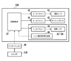
図2は、図1のインクジェット記録装置100の制御系のブロック構成図である。インクジェット記録装置100は、インターフェイス40を介して、ホスト装置としてのホストコンピュータ(以下、「ホストPC」という)110等のデータ供給装置に接続されている。データ供給装置から送信される各種データ、および記録に関連する制御信号等は、インクジェット記録装置100の記録制御部47に入力される。記録制御部47は、インターフェイス40を介して入力された制御信号にしたがって、後述のモータドライバ43,44およびヘッドドライバ45を制御する。また、記録制御部47は、入力される画像データの処理、および後述のヘッド種別信号発生回路46より入力される信号の処理を行う。41は、記録媒体17を搬送させるための搬送ローラ13を回転させる搬送モータである。42は、記録ヘッド21〜26を搭載するキャリッジ18を往復移動させるためのキャリッジモータである。43,44は、搬送モータ41,キャリッジモータ42をそれぞれ駆動するためのモータドライバである。45は、記録ヘッド21〜26を駆動するためのヘッドドライバであり、記録ヘッドの数に対応して複数設けられている。また、46はヘッド種別信号発生回路であり、キャリッジ18に搭載されている記録ヘッド21〜26の種類や数を示す信号を記録制御部47に供給する。
FIG. 2 is a block configuration diagram of a control system of the
図3は、インクジェット記録装置とホストPCとで構成される画像処理システムにおいて、画像データの処理系の機能ブロック図である。インクジェット記録装置100の記録制御部47は、プリンタドライバがインストールされたホストPC110から、インターフェイス40を介して転送されるデータを処理する。
FIG. 3 is a functional block diagram of an image data processing system in an image processing system including an inkjet recording apparatus and a host PC. The
ホストPC110は、アプリケーションから入力画像データD1を受け取る。この入力画像データD1は、後述する画像構成要素の種類に関する情報(画像の属性情報)関する情報を含んでいる。まず、受け取った入力画像データD1に対して、1200dpiの解像度でレンダリング処理51をすることにより、記録用の多値のRGBデータD2を生成する。本実施形態では、RGBデータD2は256値のデータである。一方、入力画像データD1に基づいて、記録すべき画像内に含まれる複数種の画像構成要素を判別するためのオブジェクト判別処理52を行う。本例の場合は、属性情報に基づいて、記録すべき画像が文字、線画、および純黒の画像であるか否かを判別する。純黒の画像は、R=0,G=0,B=0で、Kの値が最大の画像である。本例では、文字、線画および純黒の画像は、「特定画像」ともいう。オブジェクト判別処理52により判別された文字データD10、線画データD20、純黒データD30のそれぞれに対して、レンダリング処理53,54,55を施す。これにより、解像度1200dpiの2値の文字オブジェクトデータD11、2値の線画オブジェクトデータD21、および2値の純黒オブジェクトデータD31が生成される。以上のように生成された多値のRGBデータD2、および2値のオブジェクトデータD11,D21,D31は、記録制御部47に転送される。以下においては、文字の属性情報が付与された文字データD10、線画の属性情報が付与された線画データD20、および純黒データD30のそれぞれを「属性データ」、他の入力画像データを「無属性データ」ともいう。
The
記録制御部47は、多値のRGBデータD2を多値(256値)のKCMYデータD3に変換するための色変換処理61を行う。次いで、量子化処理(例えば、誤差拡散処理)62によって、多値(256値)のKCMYデータD3を量子化(2値化)する。これにより、解像度1200dpiの2値のKCMYデータD4が生成される。一方、記録制御部47に転送された2値のオブジェクトデータD11,D21,D31のそれぞれに対して、非エッジ部検出処理63,64,65を行う。これにより、エッジ部に関する2値のデータD12,D22,D32と、非エッジ部に関する2値のデータD13,D23,D33が生成される。データD12は文字のエッジ部データ、データD13は文字の非エッジ部のデータ、データD22は線画のエッジ部データ、データD23は線画の非エッジ部のデータ、データD32は純黒のエッジ部データ、データD33は純黒の非エッジ部のデータである。
The
2値のデータD4,D12,D13,D22,D23,D32,D33の内のK(ブラック)に関するデータに対しては、後述するK(ブラック)に関してのオブジェクト別データ処理が施される。このように処理されたインク色毎の記録データに基づいて、ヘッドドライバ45が記録ヘッド21〜24を制御して、各色のインクによって画像を記録する。
Of the binary data D4, D12, D13, D22, D23, D32, D33, data related to K (black), which will be described later, is subjected to object-specific data processing. Based on the recording data for each ink color processed in this way, the
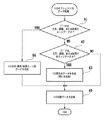
図4は、Kに関してのオブジェクト別データ処理を説明するためのフローチャートである。このオブジェクト別データ処理は、2値のデータD12,D13,D22,D23,D32,D33と、2値のKCMYデータD4の内のKデータと、を処理対象とする。 FIG. 4 is a flowchart for explaining object-specific data processing relating to K. This object-specific data processing targets binary data D12, D13, D22, D23, D32, D33 and K data in binary KCMY data D4.
まず、処理対象のデータの内、着目画素のデータ(画像データ)が文字のエッジ部のデータ(エッジデータ)、線画のエッジデータ、または純黒のエッジデータのいずれかであるか否かを判定する(ステップS1)。文字、線画、および純黒のいずれのエッジデータでもないと判定されたデータに関しては、それが文字の非エッジ部のデータ(非エッジデータ)、線画の非エッジデータ、または純黒の非エッジデータのいずれかであるか否かを判定する(ステップS2)。このように文字、線画、および純黒のいずれかの非エッジデータと判定されたデータに対して、後述するように、間引きマスクを用いる間引き処理を施す。これにより、Kの文字、線画、および純黒の非エッジ部の間引きデータを生成する(ステップS3)。一方、注目画素のデータが属性データ(文字データ、線画データ、純黒データ)でないと判断された場合(S1でNo且つS2でNo)、S2からS5へと進む。このデータは多値のKデータにおいてその値が最大とならないデータであって、2値のKCMYデータD4の内のKデータに該当する。このようなデータの一例としては、写真やコンピュータグラフィックに含まれるKデータである。 First, it is determined whether or not the data of the target pixel (image data) is one of the edge data of the character (edge data), the edge data of the line drawing, or the edge data of pure black. (Step S1). For data determined not to be edge data of character, line drawing, or pure black, it is non-edge data (non-edge data) of character, non-edge data of line drawing, or non-edge data of pure black It is determined whether or not any of the above (step S2). As described later, thinning processing using a thinning mask is performed on data determined as non-edge data of any one of characters, line drawings, and pure black in this way. As a result, thinned data of K characters, line drawings, and non-edge portions of pure black is generated (step S3). On the other hand, when it is determined that the data of the pixel of interest is not attribute data (character data, line drawing data, pure black data) (No in S1 and No in S2), the process proceeds from S2 to S5. This data is data whose value does not become maximum in multi-value K data, and corresponds to K data in binary KCMY data D4. An example of such data is K data included in photographs and computer graphics.
ステップS1において、文字、線画、または純黒のエッジデータと判定された画像データは、Kの文字,線画,および純黒のエッジデータが合成される(ステップS4)。ステップS3およびS4にて生成されデータと、ステップS2において文字、線画、および純黒のいずれの非エッジデータではないと判定されたデータ(2値のKCMYデータD4の内のKデータ)は、Kの記録データを生成するように合成される(ステップS5)。 In step S1, the image data determined as character, line drawing, or pure black edge data is combined with K character, line drawing, and pure black edge data (step S4). The data generated in steps S3 and S4 and the data determined as not non-edge data of character, line drawing, or pure black in step S2 (K data in binary KCMY data D4) are K Are combined so as to generate recording data (step S5).
このように生成されたKの記録データに基づいて、後述するように、エッジ用黒、非エッジ用黒、エッジ用黒のインクを吐出する記録ヘッド21,22,23からブラックインクを吐出する。 Based on the K recording data generated in this way, black ink is ejected from the recording heads 21, 22, and 23 that eject ink for black for edges, black for non-edges, and black for edges, as will be described later.
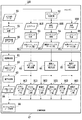
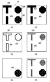
図5は、入力画像データD1からオブジェクト別データ処理によってKの記録データが生成されるまでの処理の概略を説明するための図である。入力画像D1が入力されると、オブジェクト判別処理52によって、入力画像データD1に含まれる属性データが判別される。同図(a)は、入力画像データD1に対するオブジェクト判別処理52の判定結果を図示しており、入力画像データD1には、文字データD10、線画データD20、純黒データD30が含まれている。また、エッジ部検出処理63〜65により、文字データD10、線画データD20、純黒データD30はそれぞれ、エッジ部データと非エッジ部データとに判別される。
FIG. 5 is a diagram for explaining the outline of the processing from the input image data D1 until the K recording data is generated by the object-specific data processing. When the input image D1 is input, the
次に、オブジェクト別データ処理66では、属性データは、S1およびS2を経ることにより、エッジ部に関するデータD12,D22,D32(図5(b))と、非エッジ部に関するデータD13,D23,D33(図5(c))とに分けられる。図5(c)に示す非エッジ部に関するデータD13,D23,D33に対して、図4のS3において間引き処理が行われて、間引きデータD14,D24,D34が生成される(図5(d))。本例の間引きデータは、間引きマスクを用いて非エッジ部データを50%間引くことによって生成される。
Next, in the object-
そして、このようにして生成された非エッジ部の間引きデータは、図4のS5においてエッジデータと合成され、Kの記録データが生成される。尚、入力画像データD1に特定画像以外の画像(2値のKCMYデータD4の内のKデータD41)が含まれる場合には、このタイミングでデータD41も合成される。そして、Kの記録データに基づいて記録ヘッドが駆動され記録が行われる。 Then, the non-edge portion thinned data generated in this way is combined with the edge data in S5 of FIG. 4, and K recording data is generated. When the input image data D1 includes an image other than the specific image (K data D41 of the binary KCMY data D4), the data D41 is also synthesized at this timing. Based on the K recording data, the recording head is driven to perform recording.
画像データからのエッジデータの抽出、および非エッジデータ生成方法は、当該事業者らにおいては周知であるため、ここでは説明を省略する。また本例では、入力データを多値のRGBデータD2とした。しかし、入力データを多値のCMYKデータ、または2値のCMYKデータなどとしてもよく、この場合にも同様の効果を得ることができる。 The extraction of edge data from image data and the method for generating non-edge data are well known to the business operators, and thus the description thereof is omitted here. In this example, the input data is multi-value RGB data D2. However, the input data may be multivalued CMYK data, binary CMYK data, or the like. In this case, the same effect can be obtained.
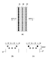
図6(a)は、記録ヘッド21〜26の内のブラックインクに関する3つの記録ヘッド21,22,23を示し、これらは、前述したKの記録データに基づいてインクを吐出する。記録ヘッド21および23から吐出されるエッジ用の黒インクは緩浸透インクであり、記録ヘッド22から吐出される非エッジ用の黒インクは超浸透インクである。記録ヘッドを矢印X2の復方向に走査させる場合には、記録ヘッド22,23を用いる。すなわち、図6(b)のように、まずは、画像の内部領域(非エッジデータによる記録領域、および無属性データによる記録領域)を記録ヘッド22から吐出する超浸透インクにより記録する。その後、画像の外周領域(エッジデータによる記録領域)を記録ヘッド23から吐出する緩浸透インクにより記録する。一方、記録ヘッドを矢印X1の往方向に走査させる場合には、記録ヘッド21,22を用いる。すなわち、図6(c)のように、まずは、内部領域(非エッジデータによる記録領域、および無属性データによる記録領域)を記録ヘッド22から吐出する超浸透インクにより記録する。その後、外周領域(エッジデータによる記録領域)を記録ヘッド21から吐出する緩浸透インクにより記録する。一方、特定画像以外の画像に対しては、記録ヘッド22から吐出する超浸透インクにより記録し、滲みのない高品位の画像を記録することができる。尚、以上の説明では、文字、線画、純黒画像を「特定画像」とし、これらにエッジ処理を行うようにした。しかし、純黒画像は写真やグラフィック中のKの値が最大となるの領域(画素領域)であり、写真やグラフィック中のこの領域だけエッジ処理を行うと、画像の均一性の低下を招くおそれがある。そのため、文字、線画のみを「特定画像」としてエッジ処理するようにしてもよい。
FIG. 6A shows three recording heads 21, 22, and 23 relating to black ink among the recording heads 21 to 26, and these eject ink based on the K recording data described above. The black ink for edges discharged from the recording heads 21 and 23 is a slowly penetrating ink, and the black ink for non-edge discharged from the
以上のとおり、ドットが高密度に形成される特定画像(文字、線画)を記録するときには、浸透性の異なるインクを効果的に用いることにより、その特定画像の外形を明確に記録することができる。また一方で、写真、グラフィック等の画像に対しては、Kの値が最大となる画素領域(純黒)にのみエッジ処理を行うか、または全くエッジ処理を行わないため、階調の段差の発生などの影響を軽減することが可能となる。 属性データによる記録領域との関連において、外周領域は、その属性データによる記録領域に含まれ、かつドットが形成されない不記録領域と接し、内部領域は、その属性データによる記録領域に含まれ、かつ外周領域と接する。 As described above, when recording a specific image (characters, line drawings) in which dots are formed with high density, the outer shape of the specific image can be clearly recorded by effectively using inks having different permeability. . On the other hand, for images such as photographs and graphics, edge processing is performed only on the pixel region (pure black) where the value of K is the maximum, or no edge processing is performed at all, so that there is no level difference in gradation. It is possible to reduce the influence such as occurrence. In relation to the recording area by the attribute data, the outer peripheral area is included in the recording area by the attribute data and touches the non-recording area in which dots are not formed, the inner area is included in the recording area by the attribute data, and It touches the outer peripheral area.
本例において使用する超浸透インクおよび緩浸透インクの組成は、次の通りである。なお、各成分の割合は質量部で示したものである(各成分の合計は100質量部)。 The composition of the super-penetration ink and the slow-penetration ink used in this example is as follows. In addition, the ratio of each component is shown by the mass part (the sum total of each component is 100 mass parts).
(超浸透インク)
顔料分散液 50質量部
グリセリン 6質量部
ジエチレングリコール 5質量部
アセチレノールEH(川研ファインケミカル製) 1質量部
水 残部
(Super penetrating ink)
Pigment dispersion 50 parts by weight Glycerin 6 parts by
(緩浸透インク)
顔料分散液 50質量部
グリセリン 6質量部
ジエチレングリコール 5質量部
アセチレノールEH(川研ファインケミカル製) 0.1質量部
水 残部
また、上記顔料分散液次のようにして得た。
(Slow penetration ink)
Pigment dispersion 50 parts by weight Glycerin 6 parts by
[顔料分散液]
表面積が230m2/gでDBP吸油量が70ml/100gのカーボンブラック10gと、p−アミノ安息香酸3.41gと、を水72gによく混合した後、これに硝酸1.62gを滴下して70℃で攪拌した。数分後、5gの水に1.07gの亜硝酸ナトリウムを溶かした溶液を加え、更に1時間攪拌した。得られたスラリーを東洋濾紙No.2(アドバンティス社製)でろ過し、顔料粒子を十分に水洗し、90℃のオーブンで乾燥させた後、この顔料に水を足して顔料濃度10質量%の顔料水溶液を作成した。以上の方法により、表面にフェニル基を介して親水性基が結合して、アニオン性に帯電した自己分散型カーボンブラックが分散された顔料分散液を得た。
[Pigment dispersion]
10 g of carbon black having a surface area of 230 m2 / g and a DBP oil absorption of 70 ml / 100 g and 3.41 g of p-aminobenzoic acid were mixed well with 72 g of water, and then 1.62 g of nitric acid was added dropwise thereto at 70 ° C. And stirred. Several minutes later, a solution of 1.07 g of sodium nitrite dissolved in 5 g of water was added, and the mixture was further stirred for 1 hour. The obtained slurry was Toyo Filter Paper No. The mixture was filtered through 2 (manufactured by Advantis), the pigment particles were sufficiently washed with water and dried in an oven at 90 ° C., and water was added to the pigment to prepare an aqueous pigment solution having a pigment concentration of 10% by mass. By the above method, a pigment dispersion in which a hydrophilic group was bonded to the surface via a phenyl group and an anionically charged self-dispersing carbon black was dispersed was obtained.
本例においては、アセチレノールEH(商品名;川研ファインケミカル社製)(エチレンオキサイド−2,4,7,9−テトラメチル−5−デシン−4,7−ジオール(ethylene oxide−2,4,7,9−tetramethyl−5−decyne−4,7−diol))という界面活性剤によって、超浸透インクと緩浸透インクの浸透性を相対的に変化させている。しかし、他の溶剤によって浸透性を変化させてもよい。 In this example, acetylenol EH (trade name; manufactured by Kawaken Fine Chemical Co., Ltd.) (ethylene oxide-2,4,7,9-tetramethyl-5-decyne-4,7-diol (ethylene oxide-2,4,7) , 9-tetramethyl-5-decyne-4,7-diol)), the permeability of the super-penetrating ink and the slow-penetrating ink is relatively changed. However, the permeability may be changed by another solvent.
インクの組成は、記録装置の型式や記録媒体の種類などによって選択すべきである。上記組成は一例であり、本発明は、同一色相であって、相対的な浸透性が異なる2つのインクを用いることができればよい。 The composition of the ink should be selected depending on the type of recording apparatus and the type of recording medium. The above composition is an example, and the present invention only needs to be able to use two inks having the same hue and different relative penetrability.
緩浸透インクによる記録領域は、超浸透インクによる記録領域と比較して、記録媒体上に露出する顔料分散体が多いため耐擦過性や耐マーカー性は劣る。そのため、緩浸透インクの顔料分散液重量比を超浸透性インクよりも少なくして、記録媒体上に露出する顔料分散体を減らすことにより、耐擦過性能と耐マーカー性を向上させることができる。超浸透インクに対する緩浸透インクの顔料分散液の重量比低減の程度は、記録装置の型式などに応じて調整すればよい。 The recording area with the slowly penetrating ink is inferior in scratch resistance and marker resistance because there are more pigment dispersions exposed on the recording medium than the recording area with the super penetrating ink. Therefore, the scratch resistance and marker resistance can be improved by reducing the pigment dispersion weight ratio of the slowly penetrating ink to less than the super penetrating ink and reducing the pigment dispersion exposed on the recording medium. The degree of reduction in the weight ratio of the pigment dispersion of the slow osmosis ink to the super osmosis ink may be adjusted according to the type of the recording apparatus.
本例で用いた色材は自己分散型顔料と称されるものであり、顔料粒子に親水基が付いている。一方、樹脂分散型顔料と称される色材は、顔料粒子に樹脂が付いており、その樹脂の親水基が水溶性を発揮する。発明者らの実験では、樹脂分散型顔料を用いた場合でも発明の効果は得られたが、自己分散型顔料を使用した場合にはより望ましい効果が得られた。 The color material used in this example is called a self-dispersing pigment, and the pigment particles have a hydrophilic group. On the other hand, in a coloring material called a resin dispersion type pigment, a resin is attached to pigment particles, and the hydrophilic group of the resin exhibits water solubility. In the experiments conducted by the inventors, the effect of the invention was obtained even when the resin-dispersed pigment was used, but a more desirable effect was obtained when the self-dispersed pigment was used.
以上のように、画像構成要素の種類に関する情報(属性データ)に基づいて、超浸透性インクと緩浸透インクを選択的に用いる。すなわち、エッジ処理によって、文字、線画、純黒の画像の内部領域(非エッジ部)を浸透速度が速いインクを用いて記録することにより、耐擦過性や耐マーカー性を向上させることができる。さらに、画像の外周領域(エッジ部)は浸透速度が遅いインクを用いて記録することにより、画像端部のシャープネスを向上させることができ、文字品位や線品位が向上する。また、内部領域(非エッジ部)の記録データが間引かれることにより、記録媒体上でブリードやフェザリングを発生させずに、高品位の画像を記録することができる。さらに無属性データによって記録される写真のような自然画や黒色のグラデーション画像などにおいては、超浸透インクのみを使用することによって、画像品位を低下させることなく記録媒体に画像を記録することができる。 As described above, the super-penetrating ink and the slow-penetrating ink are selectively used based on the information (attribute data) regarding the type of the image component. That is, the scratch resistance and the marker resistance can be improved by recording the inner region (non-edge portion) of the character, line drawing, and pure black image by using the ink having a high permeation speed. Furthermore, the outer peripheral area (edge portion) of the image is recorded using ink having a low permeation speed, whereby the sharpness of the image edge can be improved, and the character quality and line quality are improved. Further, by thinning out the recording data in the internal area (non-edge portion), it is possible to record a high-quality image without causing bleeding or feathering on the recording medium. Furthermore, in natural images such as photographs and black gradation images recorded by attribute-free data, images can be recorded on a recording medium without degrading image quality by using only super-penetrating ink. .
また、オブジェクト判別処理52などのホストPC110の機能は、それらの全て、または一部を記録装置100の記録制御部47に持たせてもよい。ホストPC110と記録装置100は記録システムとして機能してもよく、図3の種々の処理部はホストPC110と記録装置100に分けて備えることができる。
Further, all or some of the functions of the
(第2の実施形態)
第1の実施形態においては、属性データの非エッジ部に対して、間引きマスクを用いて間引き処理(ステップS3)を行った。本実施形態では、その間引き処理における間引き率を記録媒体の浸透性に応じて変更する。そのために、記録媒体の浸透性に応じて間引きマスクを変更する。
(Second Embodiment)
In the first embodiment, the thinning process (step S3) is performed on the non-edge portion of the attribute data using the thinning mask. In the present embodiment, the thinning rate in the thinning process is changed according to the permeability of the recording medium. Therefore, the thinning mask is changed according to the permeability of the recording medium.
記録媒体の種類に応じて間引きマスクを変更する理由は、記録媒体として、インク吸収特性がさまざまなものが上市されているためである。本発明者らによる動的浸透性テスター(EMCO社製)を用いての実験の結果、記録媒体としての普通紙は、インクの浸透性に応じて概ね3つのタイプに分類することができた。浸透性の高い記録媒体は、インクの吸収が速やかであるため、ブリードやフェザリングの発生が少ない。一方、浸透率の低い記録媒体は、インクの吸収が緩やかであるため、ブリードやフェザリングが発生しやすい傾向にある。 The reason why the thinning mask is changed according to the type of the recording medium is that various types of ink absorption characteristics are marketed as recording media. As a result of an experiment using a dynamic permeability tester (manufactured by EMCO) by the present inventors, plain paper as a recording medium could be roughly classified into three types according to ink permeability. A recording medium with high penetrability absorbs ink quickly, so that bleeding and feathering are less likely to occur. On the other hand, a recording medium with a low permeability tends to cause bleeding and feathering because ink absorption is gradual.
記録媒体の浸透性に関するデータ(浸透性属性データ)は、ユーザ指示により、ホストPC110上のプリンタドライバから、インターフェイス40を介して記録制御部47に入力される。図4のステップS2において、属性データ(文字、線画、純黒データ)の非エッジ部と判定された画像データは、ステップS3において間引き処理される。その間引き処理における間引き率は、記録媒体の浸透性に応じて予め設定されている。本例においては、浸透率の高い記録媒体の群をA、それが中間の群をB、それが低い群をCとした。A群の記録媒体を用いた場合の間引き率は0%(間引かない)、B群の場合は25%、C群の場合は50%とした(A=0%(間引かない)、B=25%、C=50%)。
Data relating to the permeability of the recording medium (penetration attribute data) is input from the printer driver on the
図7は、本実施形態において、入力画像データD1からオブジェクト別データ処理によってKの記録データが生成されるまでの処理の概略を説明するための図である。同図は、文字、線画、および純黒の画像の非エッジ部に対する間引き処理において、浸透性属性データとしてC=50%が選択されたときの説明図である。 FIG. 7 is a diagram for explaining the outline of the processing until K recording data is generated from the input image data D1 by the object-specific data processing in the present embodiment. This figure is an explanatory diagram when C = 50% is selected as the permeability attribute data in the thinning process for the non-edge portion of the character, line drawing, and pure black image.
図7(a)は、入力画像D1を図示しており、この入力画像D1には文字データD10、線画データD20、純黒データD30、および無属性データ(2値のKCMYデータD4の内のKデータD41)が含まれている。入力画像データD1は、オブジェクト判別処理52によって、入力画像データD1に含まれる属性データが判別され、同図(b)のように、文字データD10、線画データD20、純黒データD30が判別される。また、これら属性データは、エッジ部検出処理63〜65により、エッジ部データと非エッジ部データとに判別される。
FIG. 7A shows an input image D1, which includes character data D10, line drawing data D20, pure black data D30, and non-attribute data (K in binary KCMY data D4). Data D41) is included. In the input image data D1, attribute data included in the input image data D1 is determined by the
次に、オブジェクト別データ処理66では、属性データは、S1およびS2を経ることにより、エッジ部に関するデータD12,D22,D32(図7(c))と、非エッジ部に関するデータD13,D23,D33とに分けて生成される。非エッジ部のデータは、図7(b)のデータと、図7(c)のデータと、の否定論理積によって得ることができる。この非エッジ部のデータは、間引き率50%のマスクとの論理積をとる間引き処理(ステップS3)が行われて、間引きデータD14,D24,D34が得られる(図7(d))。図7(e)は、無属性データである2値のKデータD41を示している。
Next, in the
そして、このようにして生成されたエッジ部のデータ、非エッジ部の間引きデータ、および無属性データである2値のKデータD41は合成生成され(ステップS5)、このKの記録データに基づいて記録ヘッドが駆動され記録が実行される。具体的には、記録データのうち、図7(c)のエッジデータが緩浸透インクによって記録され、図7(f)のデータが超浸透インクによって記録される。 この非エッジデータと、間引き率50%のマスクと、の論理積をとる間引き処理(ステップS3)によって、図7(d)のデータ34a,34b,34c)が得られる。図7(e)は、無属性データである2値のKデータD41である。図7(f)は、図7(d)のデータと、図7(e)のデータD41と、の論理和をとったデータである。 Then, the edge portion data, the non-edge portion thinned data, and the binary K data D41, which are non-attribute data, are synthesized and generated (step S5). The recording head is driven and recording is performed. Specifically, among the recording data, the edge data in FIG. 7C is recorded with the slow penetrating ink, and the data in FIG. 7F is recorded with the super penetrating ink. Data 34a, 34b, 34c) of FIG. 7D is obtained by thinning processing (step S3) that takes the logical product of this non-edge data and a mask with a thinning rate of 50%. FIG. 7E shows binary K data D41, which is attribute-free data. FIG. 7 (f) is data obtained by ORing the data of FIG. 7 (d) and the data D41 of FIG. 7 (e).
本実施形態においては、使用する記録媒体の浸透性をユーザがドライバ上で選択することにより、記録媒体の浸透性に適した非エッジデータの間引き処理(間引き率が異なる間引き処理)を行う。これにより、記録媒体上でのブリードやフェザリングの発生を抑えて、高品位の画像を記録することができる。なお、記録媒体の情報を取得する方法は、上記実施形態に限定されるものではない。例えば、発光素子と受光素子とから成る光学センサを記録装置に設けて、記録媒体の正反射光や拡散反射光に基づいて記録媒体の種類を判別し、その判別結果から記録媒体の浸透性を推定するようにしてもよい。 In this embodiment, when the user selects the permeability of the recording medium to be used on the driver, non-edge data thinning processing (thinning processing with different thinning rates) suitable for the permeability of the recording medium is performed. As a result, it is possible to record high-quality images while suppressing the occurrence of bleeding and feathering on the recording medium. Note that the method for acquiring information on the recording medium is not limited to the above embodiment. For example, an optical sensor composed of a light emitting element and a light receiving element is provided in the recording apparatus, the type of the recording medium is determined based on the regular reflection light or diffuse reflection light of the recording medium, and the permeability of the recording medium is determined from the determination result. You may make it estimate.
(第3の実施形態)
前述した第1および第2の実施形態1,2においては、マスクを用いて属性データの非エッジデータを間引き処理した後に、その間引かれた非エッジデータを超浸透性インクのみによって記録した。本実施形態では、非エッジデータを記録するために、超浸透性インクのみならず緩浸透インクをも用いる。
(Third embodiment)
In the first and
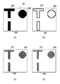
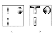
本例においては、図7(d)のような間引き率50%の非エッジデータとは別に、間引き率が25%のマスクを用いる間引き処理(ステップS3)によって、図8(a)のような間引き率20%の非エッジデータを生成する。図8(b)は、図8(a)の非エッジデータと図6(c)のエッジデータとの論理和をとったデータである。 In this example, apart from non-edge data with a thinning rate of 50% as shown in FIG. 7D, thinning processing using a mask with a thinning rate of 25% (step S3), as shown in FIG. Non-edge data with a thinning rate of 20% is generated. FIG. 8B shows data obtained by ORing the non-edge data of FIG. 8A and the edge data of FIG. 6C.
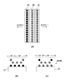
図9(a)は、記録ヘッド21〜26の内のブラックインクに関する3つの記録ヘッド21,22,23を示す。前述したように、記録ヘッド21および23から吐出されるエッジ用の黒インクは緩浸透インクであり、記録ヘッド22から吐出される非エッジ用の黒インクは超浸透インクである。図9(b)は、復方向の走査時における記録ヘッド21〜23からのインクの吐出順序の説明図であり、図9(c)は、往方向の走査時における記録ヘッド21〜23からのインクの吐出順序の説明図である。
FIG. 9A shows three recording heads 21, 22, and 23 related to black ink among the recording heads 21 to 26. As described above, the black ink for edges ejected from the recording heads 21 and 23 is a slow penetration ink, and the black ink for non-edges ejected from the
復方向の走査時には、図9(b)のように、まず、図8(b)のデータによって記録ヘッド21から緩浸透インクを吐出して、外周領域(エッジ部)および内部領域(非エッジ部)を記録する。次に、図8(a)のデータによって記録ヘッド22から超浸透インクを吐出して、内部領域(非エッジ部)にのみを記録する。その後、図7(c)のデータによって記録ヘッド23から緩浸透インクを吐出して、外周領域(エッジ部)にのみを記録する。
At the time of scanning in the backward direction, as shown in FIG. 9B, first, slowly penetrating ink is ejected from the
一方、往方向の走査時には、図9(c)のように、まず、図8(b)のデータによって記録ヘッド23から緩浸透インクを吐出して、外周領域(エッジ部)および内部領域(非エッジ部)を記録する。次に、図8(a)のデータによって記録ヘッド22から超浸透インクを吐出して、内部領域(非エッジ部)にのみを記録する。その後、図7(c)のデータによって記録ヘッド21から緩浸透インクを吐出して、外周領域(エッジ部)にのみを記録する。
On the other hand, when scanning in the forward direction, as shown in FIG. 9C, first, slowly penetrating ink is ejected from the
このような往方向および復方向の走査時に、記録ヘッド22から吐出された超浸透インクは、それよりも先行して記録媒体17に付与されている緩浸透インクの上に付与される。緩浸透インクは、浸透しにくいインクであって浸透速度が遅いため、記録ヘッド22から吐出される超浸透インクが記録媒体17の表面に着弾するまで、記録媒体の表面に留まっている。そのため、緩浸透インクと超浸透インクとが記録媒体の表面上で混合することになり、両者の浸透速度が平均化されて、緩浸透インクのみで記録した領域よりはインクの浸透速度が速くなる。このように、浸透速度が速いインク(緩浸透インクと超浸透インクとの混合インク)によって、画像の内部領域(非エッジ部)を記録することにより、耐擦過性や耐マーカー性を向上させることができる。
During such forward and backward scans, the super-penetrating ink ejected from the
往方向および復方向の走査時において、最後続の記録ヘッド(往方向の走査時は記録ヘッド21、復方向の記録時は記録ヘッド23)から吐出される緩浸透インクは、それよりも先に記録媒体状に着弾している緩浸透インクの上に着弾する。緩浸透インクは、浸透しにくいインクであって浸透速度が遅いため、その緩浸透インクが最後続の記録ヘッドから吐出されて記録媒体の表面に着弾するまでは、それよりも先に着弾している緩浸透インクが記録媒体の表面に留まっている。先に着弾した緩浸透インクと、後に着弾した緩浸透インクと、が記録媒体の表面で混合しても浸透速度は速くはならない。このように、画像の外周領域(エッジ部)を浸透速度が遅いインクによって記録することにより、画像端部のシャープネスを向上させて、文字や線の記録画像の品位を向上させることができる。
During forward scanning and backward scanning, the slowly penetrating ink ejected from the last recording head (the
なお、本例では、内部領域(非エッジ部)に対しては、最後続の記録ヘッド(往方向の走査時は記録ヘッド21、復方向の記録時は記録ヘッド23)から緩浸透インクを吐出しないが、それを吐出してもよい。その場合には、内部領域の光学濃度が上がるものの、耐擦過性や耐マーカー性が若干低下するおそれがある。最後続の記録ヘッドからインクを付与するか否かは、記録装置毎に設定することができる。先行の記録ヘッド(往方向の走査時は記録ヘッド23、復方向の記録時は記録ヘッド21)から吐出する緩浸透インクによって記録される内部領域の記録率は、超浸透インクで記録される内部領域の記録率以下であることが望ましい。記録率は、単位記録領域に対するインクの付与量に相当し、記録データの間引き率に対応する。
In this example, the slow penetration ink is ejected from the last recording head (the
本実施形態の場合は、内部領域において超浸透インクと緩浸透インクとを記録媒体上で混合することにより、記録濃度の向上を図りながら、記録媒体上でのブリードやフェザリングの発生を抑えて、高品位の画像を記録することができる。 In the case of the present embodiment, super-penetrating ink and slow-penetrating ink are mixed on the recording medium in the inner region, thereby suppressing the occurrence of bleeding and feathering on the recording medium while improving the recording density. High-quality images can be recorded.
(他の実施形態)
前述した実施形態においては、浸透性が比較的高いインク(第1のインク)および浸透性が比較的低いインク(第2のインク)として、ブラックのインクを用いた。しかし、このような第1および第2のインクはブラックインクのみに特定されず、略同一色相を有する同色系のインクであればよい。所定の色の文字および線図の内の少なくとも一方を特定画像として、その特定画像を浸透性の異なる第1および第2のインクによって記録することができる。また、第1のインクの色材濃度は、第2のインクの色材濃度よりも高くてもよい。
(Other embodiments)
In the embodiment described above, black ink is used as the ink having a relatively high permeability (first ink) and the ink having a relatively low permeability (second ink). However, such first and second inks are not limited to black inks, and may be inks of the same color having substantially the same hue. It is possible to record at least one of a character and a diagram of a predetermined color as a specific image, and the specific image can be recorded by the first and second inks having different permeability. The color material concentration of the first ink may be higher than the color material concentration of the second ink.
前述した実施形態の機能は、コンピュータがプログラムを実行することにより実現することができ、そのプログラムおよびそのプログラムを記憶した記憶媒体は本発明を構成することになる。 The functions of the above-described embodiments can be realized by a computer executing a program, and the program and a storage medium storing the program constitute the present invention.
17 記録媒体
21〜26 記録ヘッド
47 記録制御部
100 記録装置
110 ホストPC(ホスト装置)
17 Recording Medium 21-26
Claims (11)
前記記録ヘッドは、第1のインクと、当該第1のインクと同色系のインクで且つ前記第1のインクよりも浸透性が低い第2のインクと、を吐出可能であり、
前記インクジェット記録装置は、文字および線画により構成される特定画像を前記第1および第2のインクを用いて記録し、前記特定画像以外の画像を前記第2のインクを用いずに第1のインクを用いて記録するための制御手段を備え、
前記制御手段は、前記特定画像の外周領域を前記第1のインクは用いずに前記第2のインクによって記録し、前記特定画像の内部領域を前記第2のインクは用いずに前記第1のインクによって記録する
ことを特徴とするインクジェット記録装置。 In an inkjet recording apparatus that records an image by ejecting ink from a recording head based on recording data and forming dots on a recording medium,
The recording head is capable of ejecting a first ink and a second ink having the same color as the first ink and having a lower permeability than the first ink.
The inkjet recording apparatus records a specific image composed of characters and line drawings using the first and second inks, and images other than the specific image are printed using the first ink without using the second ink. Control means for recording using,
The control unit records the outer peripheral area of the specific image with the second ink without using the first ink, and the inner area of the specific image without using the second ink. An ink jet recording apparatus for recording with ink.
前記制御手段は、前記間引き手段によって間引かれた記録データに基づいて、前記内部領域を記録することを特徴とする請求項1に記載のインクジェット記録装置。 Comprising thinning means for thinning out the recording data corresponding to the internal area;
2. The ink jet recording apparatus according to claim 1, wherein the control unit records the internal area based on the recording data thinned out by the thinning unit.
前記制御手段は、前記特定画像に関する属性情報が付与された前記記録データに基づいて、前記特定画像を記録する
ことを特徴とする請求項1から3のいずれかに記載のインクジェット記録装置。 A discriminator for discriminating attribute information relating to the specific image given to the recording data;
4. The inkjet recording apparatus according to claim 1, wherein the control unit records the specific image based on the recording data to which attribute information related to the specific image is added. 5.
前記特定画像は、R=0,G=0,B=0の画像を含む
ことを特徴とする請求項1から5のいずれかに記載のインクジェット記録装置。 The first and second inks are black inks,
The inkjet recording apparatus according to claim 1, wherein the specific image includes an image of R = 0, G = 0, and B = 0.
前記記録ヘッドは、第1のインクと、当該第1のインクと同色系のインクで且つ前記第1のインクよりも浸透性が低い第2のインクと、を吐出可能であり、
前記インクジェット記録装置は、文字および線画の特定画像を前記第1および第2のインクを用いて記録し、記録前記特定画像以外の画像を前記第2のインクを用いずに第1のインクを用いて記録するための制御手段を備え、
前記制御手段は、前記特定画像の外周領域を前記第1のインクは用いずに前記第2のインクによって記録し、前記特定画像の内部領域を前記第1のインクおよび前記第2のインクによって記録し、
前記内部領域における前記第2のインクの記録率は、前記内部領域における前記第1のインクの記録率以下である
ことを特徴とするインクジェット記録装置。 In an inkjet recording apparatus that records an image by ejecting ink from a recording head based on recording data and forming dots on a recording medium,
The recording head is capable of ejecting a first ink and a second ink having the same color as the first ink and having a lower permeability than the first ink,
The inkjet recording apparatus records a specific image of characters and line drawings using the first and second inks, and uses the first ink for images other than the recorded specific image without using the second ink. Control means for recording,
The control means records the outer peripheral area of the specific image with the second ink without using the first ink, and records the inner area of the specific image with the first ink and the second ink. And
The inkjet recording apparatus, wherein a recording rate of the second ink in the inner region is equal to or lower than a recording rate of the first ink in the inner region.
前記記録ヘッドは、第1のインクと、当該第1のインクと同色系のインクで且つ前記第1のインクよりも浸透性が低い第2のインクと、を吐出可能であり、
前記インクジェット記録方法は、文字および線画の特定画像を前記第1および第2のインクを用いて記録記録し、記録前記特定画像以外の画像を前記第2のインクを用いずに第1のインクを用いて記録するための制御工程を含み、
前記制御工程では、前記特定画像の外周領域を前記第1のインクは用いずに前記第2のインクによって記録し、前記特定画像の内部領域を前記第2のインクは用いずに前記第1のインクによって記録する
ことを特徴とするインクジェット記録方法。 In an inkjet recording method for recording an image by ejecting ink from a recording head based on recording data and forming dots on a recording medium,
The recording head is capable of ejecting a first ink and a second ink having the same color as the first ink and having a lower permeability than the first ink.
In the inkjet recording method, a specific image of characters and line drawings is recorded and recorded using the first and second inks, and an image other than the recorded specific image is printed using the first ink without using the second ink. Including a control step for recording using
In the control step, the outer peripheral area of the specific image is recorded by the second ink without using the first ink, and the inner area of the specific image is recorded by using the first ink without using the second ink. An ink-jet recording method comprising recording with ink.
前記記録ヘッドは、第1のインクと、当該第1のインクと同色系のインクで且つ前記第1のインクよりも浸透性が低い第2のインクと、を吐出可能であり、
前記インクジェット記録装置は、文字および線画の特定画像を前記第1および第2のインクを用いて記録記録し、記録前記特定画像以外の画像を前記第2のインクを用いずに第1のインクを用いて記録するための制御工程を含み、
前記制御工程では、前記特定画像の外周領域を前記第1のインクは用いずに前記第2のインクによって記録し、前記特定画像の内部領域を前記第1のインクおよび前記第2のインクによって記録し、
前記内部領域における前記第2のインクの記録率は、前記内部領域における前記第1のインクの記録率以下である
ことを特徴とするインクジェット記録方法。 In an inkjet recording method for recording an image by ejecting ink from a recording head based on recording data and forming dots on a recording medium,
The recording head is capable of ejecting a first ink and a second ink having the same color as the first ink and having a lower permeability than the first ink.
The inkjet recording apparatus records and records a specific image of characters and line drawings using the first and second inks, and records the first ink on an image other than the recorded specific image without using the second ink. Including a control step for recording using
In the control step, an outer peripheral area of the specific image is recorded with the second ink without using the first ink, and an inner area of the specific image is recorded with the first ink and the second ink. And
The inkjet recording method, wherein a recording rate of the second ink in the internal region is equal to or less than a recording rate of the first ink in the internal region.
Priority Applications (1)
| Application Number | Priority Date | Filing Date | Title |
|---|---|---|---|
| JP2010163893A JP2012024972A (en) | 2010-07-21 | 2010-07-21 | Inkjet recording apparatus, inkjet recording method and program |
Applications Claiming Priority (1)
| Application Number | Priority Date | Filing Date | Title |
|---|---|---|---|
| JP2010163893A JP2012024972A (en) | 2010-07-21 | 2010-07-21 | Inkjet recording apparatus, inkjet recording method and program |
Publications (1)
| Publication Number | Publication Date |
|---|---|
| JP2012024972A true JP2012024972A (en) | 2012-02-09 |
Family
ID=45778517
Family Applications (1)
| Application Number | Title | Priority Date | Filing Date |
|---|---|---|---|
| JP2010163893A Pending JP2012024972A (en) | 2010-07-21 | 2010-07-21 | Inkjet recording apparatus, inkjet recording method and program |
Country Status (1)
| Country | Link |
|---|---|
| JP (1) | JP2012024972A (en) |
Cited By (1)
| Publication number | Priority date | Publication date | Assignee | Title |
|---|---|---|---|---|
| JP2023096573A (en) * | 2021-12-27 | 2023-07-07 | セイコーエプソン株式会社 | Recording device and recording method |
-
2010
- 2010-07-21 JP JP2010163893A patent/JP2012024972A/en active Pending
Cited By (1)
| Publication number | Priority date | Publication date | Assignee | Title |
|---|---|---|---|---|
| JP2023096573A (en) * | 2021-12-27 | 2023-07-07 | セイコーエプソン株式会社 | Recording device and recording method |
Similar Documents
| Publication | Publication Date | Title |
|---|---|---|
| JP4328580B2 (en) | Ink jet recording method, program for carrying out the method, and ink jet recording apparatus | |
| JP5539122B2 (en) | Image processing method and image processing apparatus | |
| US8721021B2 (en) | Inkjet printing apparatus and printing method | |
| JP5791242B2 (en) | Inkjet recording apparatus, inkjet recording method, and inkjet recording head | |
| JP2010052244A (en) | Printing apparatus | |
| JP2011025693A (en) | Inkjet recording device, inkjet recording method, and program | |
| JPH10226055A (en) | Ink jet recording apparatus and recording method | |
| EP0845356B1 (en) | Ink-jet printing apparatus for performing printing with ink and printing ability improving liquid | |
| JP3313977B2 (en) | Ink jet recording method and ink jet recording apparatus | |
| JP2010052248A (en) | Printing apparatus | |
| JP5473257B2 (en) | Inkjet recording apparatus and inkjet recording method | |
| JP2010052208A (en) | Apparatus and method of printing | |
| JP2006326913A (en) | Image processing method, image forming apparatus, and program | |
| JP2010052245A (en) | Apparatus and head for printing | |
| JP6161282B2 (en) | Image processing method and image processing apparatus | |
| JP2005007649A (en) | Inkjet recording method, recording system, and printer driver | |
| JP6141124B2 (en) | Inkjet recording method and inkjet recording system | |
| JP4602805B2 (en) | Image processing method, image forming apparatus, image processing apparatus, program, and image forming system | |
| JP2005096365A (en) | Inkjet recording method, recording system, and printer driver | |
| JP2000037890A (en) | Ink printing method and inkjet printing apparatus | |
| JP2012024972A (en) | Inkjet recording apparatus, inkjet recording method and program | |
| JP2005088208A (en) | Inkjet recording apparatus and inkjet recording method | |
| JP2012024971A (en) | Recording apparatus and recording method | |
| JP2010143134A (en) | Inkjet recording apparatus, and inkjet recording method | |
| JP2008142972A (en) | Ink jet recording apparatus and ink jet recording method |