JP2012024970A - Ink jet printing apparatus and ink jet printing method - Google Patents
Ink jet printing apparatus and ink jet printing method Download PDFInfo
- Publication number
- JP2012024970A JP2012024970A JP2010163890A JP2010163890A JP2012024970A JP 2012024970 A JP2012024970 A JP 2012024970A JP 2010163890 A JP2010163890 A JP 2010163890A JP 2010163890 A JP2010163890 A JP 2010163890A JP 2012024970 A JP2012024970 A JP 2012024970A
- Authority
- JP
- Japan
- Prior art keywords
- recording
- ink
- recording head
- data
- recorded
- Prior art date
- Legal status (The legal status is an assumption and is not a legal conclusion. Google has not performed a legal analysis and makes no representation as to the accuracy of the status listed.)
- Granted
Links
Images
Classifications
-
- B—PERFORMING OPERATIONS; TRANSPORTING
- B41—PRINTING; LINING MACHINES; TYPEWRITERS; STAMPS
- B41J—TYPEWRITERS; SELECTIVE PRINTING MECHANISMS, i.e. MECHANISMS PRINTING OTHERWISE THAN FROM A FORME; CORRECTION OF TYPOGRAPHICAL ERRORS
- B41J2/00—Typewriters or selective printing mechanisms characterised by the printing or marking process for which they are designed
- B41J2/005—Typewriters or selective printing mechanisms characterised by the printing or marking process for which they are designed characterised by bringing liquid or particles selectively into contact with a printing material
- B41J2/01—Ink jet
- B41J2/21—Ink jet for multi-colour printing
- B41J2/2107—Ink jet for multi-colour printing characterised by the ink properties
-
- B—PERFORMING OPERATIONS; TRANSPORTING
- B41—PRINTING; LINING MACHINES; TYPEWRITERS; STAMPS
- B41J—TYPEWRITERS; SELECTIVE PRINTING MECHANISMS, i.e. MECHANISMS PRINTING OTHERWISE THAN FROM A FORME; CORRECTION OF TYPOGRAPHICAL ERRORS
- B41J2/00—Typewriters or selective printing mechanisms characterised by the printing or marking process for which they are designed
- B41J2/005—Typewriters or selective printing mechanisms characterised by the printing or marking process for which they are designed characterised by bringing liquid or particles selectively into contact with a printing material
- B41J2/01—Ink jet
- B41J2/205—Ink jet for printing a discrete number of tones
- B41J2/2052—Ink jet for printing a discrete number of tones by dot superpositioning, e.g. multipass doubling
-
- B—PERFORMING OPERATIONS; TRANSPORTING
- B41—PRINTING; LINING MACHINES; TYPEWRITERS; STAMPS
- B41J—TYPEWRITERS; SELECTIVE PRINTING MECHANISMS, i.e. MECHANISMS PRINTING OTHERWISE THAN FROM A FORME; CORRECTION OF TYPOGRAPHICAL ERRORS
- B41J2/00—Typewriters or selective printing mechanisms characterised by the printing or marking process for which they are designed
- B41J2/005—Typewriters or selective printing mechanisms characterised by the printing or marking process for which they are designed characterised by bringing liquid or particles selectively into contact with a printing material
- B41J2/01—Ink jet
- B41J2/205—Ink jet for printing a discrete number of tones
- B41J2/2056—Ink jet for printing a discrete number of tones by ink density change
-
- B—PERFORMING OPERATIONS; TRANSPORTING
- B41—PRINTING; LINING MACHINES; TYPEWRITERS; STAMPS
- B41J—TYPEWRITERS; SELECTIVE PRINTING MECHANISMS, i.e. MECHANISMS PRINTING OTHERWISE THAN FROM A FORME; CORRECTION OF TYPOGRAPHICAL ERRORS
- B41J2/00—Typewriters or selective printing mechanisms characterised by the printing or marking process for which they are designed
- B41J2/005—Typewriters or selective printing mechanisms characterised by the printing or marking process for which they are designed characterised by bringing liquid or particles selectively into contact with a printing material
- B41J2/01—Ink jet
- B41J2/21—Ink jet for multi-colour printing
- B41J2/2132—Print quality control characterised by dot disposition, e.g. for reducing white stripes or banding
Landscapes
- Engineering & Computer Science (AREA)
- Quality & Reliability (AREA)
- Ink Jet (AREA)
- Ink Jet Recording Methods And Recording Media Thereof (AREA)
Abstract
【課題】超浸透インクと緩浸透インクとを用いて記録を行う記録方法及び記録装置において、光学濃度の低下を抑制するインクジェット記録装置及びインクジェット記録方法を提供する。
【解決手段】本発明のインクジェット記録装置は、内部領域へ、相対的に記録媒体への浸透性が低い緩浸透インクと、緩浸透インクよりも記録媒体への浸透性の高い超浸透インクとを記録媒体に吐出して記録を行う。緩浸透インクと超浸透インクは同系色である。緩浸透インクによって記録される記録領域と、超浸透インクによって記録される記録領域とが、少なくとも接し、緩浸透インクを超浸透インクよりも先に記録媒体に吐出して記録を行う。
【選択図】図6Provided are an ink jet recording apparatus and an ink jet recording method for suppressing a decrease in optical density in a recording method and a recording apparatus for performing recording using super permeation ink and slow permeation ink.
An ink jet recording apparatus according to the present invention includes a slowly penetrating ink having a relatively low permeability to a recording medium and a super penetrating ink having a higher penetrability to the recording medium than a slowly penetrating ink. Recording is performed by discharging onto a recording medium. Slow penetrating ink and super penetrating ink are similar colors. The recording area recorded with the slow-penetrating ink and the recording area recorded with the super-penetrating ink are at least in contact with each other, and recording is performed by discharging the slow-penetrating ink onto the recording medium before the super-penetrating ink.
[Selection] Figure 6
Description
本発明は、記録媒体上にインクを吐出することによって画像を記録するインクジェット記録装置及びインクジェット記録方法に関する。 The present invention relates to an ink jet recording apparatus and an ink jet recording method for recording an image by ejecting ink onto a recording medium.
近年、出力装置として、インクを記録ヘッドから吐出して記録を行う形式の記録装置が広く普及している。このような記録装置の中には、記録ヘッドに形成されている吐出口からインク滴を吐出し、記録媒体上にドットを形成することによって画像を記録するものがある。インク滴で記録媒体上にドットを形成する記録では、ある領域を一色でほぼ塗りつぶす場合には、高いドット記録密度で一定の記録領域にドットが打ち込まれる。そのような場合に、一定の大きさの記録領域に対して過度に大量のインク滴が吐出されると、インクが記録領域外に滲み、記録画像の外形が明確に示された記録を行うことができないという課題があった。 2. Description of the Related Art In recent years, recording apparatuses of a type that perform recording by ejecting ink from a recording head have become widespread as output devices. Some of such recording apparatuses record an image by ejecting ink droplets from ejection ports formed in a recording head and forming dots on a recording medium. In recording in which dots are formed on a recording medium with ink droplets, when a certain area is substantially filled with one color, dots are driven into a fixed recording area with a high dot recording density. In such a case, if an excessively large amount of ink droplets are ejected to a recording area of a certain size, the ink oozes out of the recording area, and recording is performed in which the outline of the recorded image is clearly shown. There was a problem that it was not possible.
このような課題を解決するために、特許文献1には、記録領域が外周領域と内部領域とに分けられ、それぞれの記録領域に応じて記録に用いるインクを異ならせる形式のインクジェット記録装置について開示されている。特許文献1に開示された記録装置においては、外周領域では相対的に浸透性の低いインク(比較的記録媒体に浸透しにくいインク;以下、緩浸透インク)が用いられてドットが形成される。また、内部領域では相対的に浸透性の高いインク(比較的記録媒体に浸透しやすいインク;以下、超浸透インク)と、浸透性の低い緩浸透インクの両方が用いられてドットが形成される。このように、内部領域に対しては記録媒体への浸透性の異なる二種類のインクが用いられて記録が行われるので、浸透性の低い緩浸透インクのみによって記録が行われる場合に比べて記録媒体の乾燥に必要な時間が短縮され記録の高速化を図ることができる。また、内部領域が超浸透インクのみによって記録が行われる場合に比べて滲みを少なくすることができ、記録によって得られる画像の品質の低下を抑えることができる。
In order to solve such a problem,
特許文献1に開示された記録装置によって記録が行われる場合には、内部領域で浸透性の異なる二種類のインクが交互に千鳥状に並べられるようにドットが形成されて記録が行われている。そのため、内部領域では、超浸透インクによって形成されたドットと、緩浸透インクによって形成されたドットとが混在している。しかしながら、特許文献1に開示された記録装置による記録画像の内部領域では、記録媒体への浸透性の異なるインクによるドットが交互に並べられているが、記録媒体に対してインクを打ち込む順番については規定されていない。従って、記録領域に、超浸透インクが打ち込まれた後に、緩浸透インクが打ち込まれる可能性がある。そのような場合には、内部領域で、記録媒体に打ち込まれた超浸透インクにおける染料や顔料等の色材成分が記録媒体の中の深い部分へ引き込まれてしまい、ドットの濃度が低くなってしまう場合がある。そのため、記録画像の一部で濃度が不足し、これによって記録画像の品質が低下する虞がある。このような課題は、インクに含まれる色材が染料の場合にも発生することがあるが、顔料を色材に利用した場合に顕著であった。
When recording is performed by the recording apparatus disclosed in
そこで、本発明は上記の事情に鑑み、超浸透インクと緩浸透インクとを用いて記録を行うインクジェット記録装置及びインクジェット記録方法において、光学濃度の低下を抑制する記録方法および記録装置を提供することを目的とする。 Therefore, in view of the above circumstances, the present invention provides a recording method and a recording apparatus that suppress a decrease in optical density in an ink jet recording apparatus and an ink jet recording method that perform recording using super penetrating ink and slow penetrating ink. With the goal.
本発明のインクジェット記録装置は、第1のインクと、前記第1のインクと同系色で且つ前記第1のインクよりも浸透性の高い第2のインクとを吐出可能な記録ヘッドを、記録媒体に対して相対走査させることにより前記記録媒体に画像の記録を行うインクジェット記録装置であって、前記記録媒体において、記録が行われない非記録領域と隣接する外周領域に対して前記第2のインクを用いずに前記第1のインクを用いて記録を行い、前記外周領域と隣接する内部領域に対して前記第1のインクと前記第2のインクを用い、かつ、前記第1のインクを前記第2のインクよりも先に前記内部領域に吐出して記録を行うように、前記記録ヘッドからのインクの吐出を制御する記録制御手段を備えることを特徴とする。 An ink jet recording apparatus according to the present invention includes a recording head capable of ejecting a first ink and a second ink having the same color as the first ink and having a higher permeability than the first ink. An inkjet recording apparatus that records an image on the recording medium by performing relative scanning with respect to the recording medium, wherein the second ink is applied to an outer peripheral area adjacent to a non-recording area on which the recording is not performed. Recording is performed using the first ink without using the first ink, the first ink and the second ink are used for the inner region adjacent to the outer peripheral region, and the first ink is used as the first ink. It is characterized by comprising a recording control means for controlling the ejection of ink from the recording head so as to perform recording by ejecting it to the internal region prior to the second ink.
本発明のインクジェット記録装置及びインクジェット記録方法によれば、光学濃度の低下を抑制することができるので、記録画像の品質の低下を抑えることができる。 According to the ink jet recording apparatus and the ink jet recording method of the present invention, it is possible to suppress a decrease in optical density, and thus it is possible to suppress a decrease in quality of a recorded image.
以下、本発明の実施形態に係るインクジェット記録装置について、図面を参照しながら説明する。 Hereinafter, an ink jet recording apparatus according to an embodiment of the present invention will be described with reference to the drawings.
(第一実施形態)
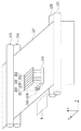
図1は、本発明を適用可能なカラーインクジェット記録装置の第一実施形態に係る構成を示す模式的な斜視図である。インクタンク207〜212は、6つのインク(ブラック(緩浸透インク)、ブラック(超浸透インク)、ブラック(緩浸透インク)、シアン、マゼンタ、イエロー:Ke、Km、Ke、C、M、Y)をそれぞれ収容している。これら6つのインクタンク207〜212からのインクを記録ヘッド201〜206に対して供給可能に構成されている。記録ヘッド201〜206は、6つのインクに対応して設けられ、インクタンク207〜212から供給されるインクをそれぞれ吐出できるように構成されている。6つの記録ヘッド201〜206のうち、ブラックのインクを吐出する記録ヘッドは、記録ヘッド201、202、203である。さらにこれらのブラックのインクを吐出する記録ヘッドのうち、本実施形態では、記録ヘッド201、203が、比較的記録媒体に浸透しにくいインク(以下、緩浸透インク)を吐出する。また、記録ヘッド202が、比較的記録媒体に浸透しやすいインク(以下、超浸透インク)を吐出する。
(First embodiment)
FIG. 1 is a schematic perspective view showing a configuration according to a first embodiment of a color inkjet recording apparatus to which the present invention is applicable. The ink tanks 207 to 212 include six inks (black (slow penetrating ink), black (super penetrating ink), black (slow penetrating ink), cyan, magenta, yellow: Ke, Km, Ke, C, M, and Y). Each housed. The inks from these six ink tanks 207 to 212 can be supplied to the
搬送ローラ103は、補助ローラ104とともに記録媒体(記録用紙)107を挟持しながら回転して記録媒体107を搬送するとともに、記録媒体107を保持する役割も担っている。キャリッジ106は、インクタンク207〜212及び記録ヘッド201〜206を搭載可能であって、これら記録ヘッド及びインクタンクを搭載しながらX方向沿って往復移動可能に構成されている。このキャリッジ106の往復移動中に記録ヘッドからインクが吐出され、これにより記録媒体に画像が記録される。記録ヘッド201〜204の回復動作時等の非記録動作時には、このキャリッジ106は図中の点線で示したホームポジション位置hに待機するように制御される。
The
図1に示すホームポジションhに待機している記録ヘッド201〜206は、記録開始命令が入力されると、キャリッジ106と共に図中X方向に移動しつつ、インクを吐出して記録媒体107上に画像を記録する。この記録ヘッドの1回の移動(走査)によって、記録ヘッド201〜206の吐出口の配列範囲に対応した幅を有する領域に対して記録が行われる。
The
キャリッジ106の主走査方向(Xの正の方向)への1回の走査に伴う記録が終了すると、キャリッジ106はホームポジションhへ向かう、主走査方向の逆方向(Xの負の方向)へ走査する。そこでまた記録ヘッド201〜206が走査を行いながら、記録ヘッド201〜206から記録媒体へインクを吐出することによって記録を行う。前回の記録走査が終了してから続く記録走査が始まる前には、搬送ローラ103が回転して、主走査方向と交差する副走査方向(Y方向)へと記録媒体が搬送される。このように記録ヘッドの記録走査と記録媒体の搬送とを繰り返すことにより記録媒体107に対する画像の記録が完成する。記録ヘッド201〜206からインクを吐出する記録動作は、後述の制御手段による制御に基づいて行われる。
When the printing accompanying one scan in the main scanning direction (X positive direction) of the
上記の例では、インクタンク207〜212と記録ヘッド201〜206とを分離可能にキャリッジ106に搭載する構成を示した。しかし、インクタンク207〜212と記録ヘッド201〜206とが一体となったカートリッジをキャリッジに搭載する形態を採用してもよい。さらに、一つの記録ヘッドから複数色のインクを吐出可能な複数色一体型の記録ヘッドをキャリッジに搭載する形態を採用してもよい。
In the above example, the configuration in which the ink tanks 207 to 212 and the recording heads 201 to 206 are detachably mounted on the
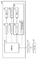
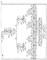
以下、記録装置のデータ生成方法を説明する。図3は、図1に示したインクジェット記録装置の記録制御系回路の概略構成を示すブロック図である。インクジェット記録装置600は、インターフェイス400を介して、ホストコンピュータ(以下、ホストPC)1200等のデータ供給装置に接続されている。データ供給装置から送信される各種データや記録に関連する制御信号等は、インクジェット記録装置600の記録制御部500に入力される。記録制御部500は、インターフェイス400を介して入力された制御信号に従って後述のモータドライバ403、404やヘッドドライバ405を制御する。また、記録制御部500は、入力される画像データの処理や後述のヘッド種別信号発生回路405より入力される信号の処理を行う。401は、記録媒体107の搬送のために搬送ローラ103を回転させるための搬送モータである。402は、記録ヘッド201〜206を搭載するキャリッジ106を往復移動させるためのキャリッジモータである。403、404は、搬送モータ401、キャリッジモータ402をそれぞれ駆動するためのモータドライバである。405は記録ヘッド201〜206を駆動するヘッドドライバであり、記録ヘッドの数に対応して複数設けられている。また、406はヘッド種別信号発生回路であり、キャリッジ106に搭載されている記録ヘッド201〜206の種類や数を示す信号を記録制御部500に供給する。
Hereinafter, a data generation method of the recording apparatus will be described. 3 is a block diagram showing a schematic configuration of a recording control system circuit of the ink jet recording apparatus shown in FIG. The ink
図4はインクジェット記録装置とホストPCとで構成される画像処理システムにおける画像データ処理を行う概略構成を示す機能ブロック図である。インクジェット記録装置の記録制御部500は、インターフェイス400を介して、プリンタドライバがインストールされたホストPC1200より転送されるデータ処理を行う。
FIG. 4 is a functional block diagram showing a schematic configuration for performing image data processing in an image processing system including an inkjet recording apparatus and a host PC. The
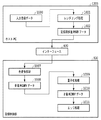
ホストPC1200では、アプリケーションから入力画像データ1000を受け取り、受け取った入力画像データ1000を1200dpi(dots/inch)の解像度でレンダリング処理1001を行う。これによって、記録用多値RGBデータ1002が生成される。本実施形態では、記録用多値RGBデータ1002は256値のデータである。生成された記録用多値RGBデータ1002は、記録制御部500に転送される。記録制御部500では、記録用多値RGBデータ1002を多値(256値)KCMYデータ1008に変換するための色変換処理1007を行う。次いで、多値(256値)KCMYデータ1008を量子化処理1009(例えば、誤差拡散)によって量子化(2値化)する。これにより、2値化されたKCMYデータが生成される。本実施形態では、解像度1200dpiの2値化されたKCMYデータが生成される。
The
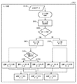
このうちの2値化されたブラックデータに対して、エッジ処理を行う。図5はエッジ処理を示す図である。まず、非エッジ部検出処理2001を行う。2値ブラックデータのうちの、非エッジ部のデータ、つまり、非エッジ部データ2003が生成される。2値ブラックデータのうちの、非エッジ部データに該当しなかったデータを、エッジ部データ2103とする。エッジ部は、記録が行われない非記録領域に隣接する外周領域であり、その外周領域に囲まれた内部領域が非エッジ部である。本実施形態では、2値化されたブラックデータのうち、エッジ部を形成するために記録されるエッジ画素として、記録対象領域の最も外側の部分(外縁)から1画素(1ドット)が選択される。それ以外のデータについては、非エッジ部データとして記録に用いられる。
Edge processing is performed on the binarized black data. FIG. 5 is a diagram showing edge processing. First, non-edge
エッジ部データ及び非エッジ部データが生成されると、エッジ部データ及び非エッジ部データのそれぞれのデータに基づいて、インクが吐出されて記録が行われる。ここで、記録媒体へインクを吐出する順序について図2を参照して説明する。 When the edge portion data and the non-edge portion data are generated, ink is ejected and recording is performed based on the data of the edge portion data and the non-edge portion data. Here, the order of ejecting ink onto the recording medium will be described with reference to FIG.
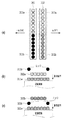
図2(a)に、図1の記録ヘッド201〜206のうちブラックのインクを吐出する記録ヘッド201〜203について示す。記録ヘッド201、203から記録するインクは緩浸透インク(比較的記録媒体に浸透しにくいインク;以下、緩浸透インク)(第1のインク)である。また、記録ヘッド202から記録するインクは超浸透インク(比較的記録媒体に浸透しやすいインク;以下、超浸透インク)(第2のインク)である。これらの緩浸透インクと超浸透インクとは、記録媒体に記録されたときに同一の色として視認される。本実施形態では、記録ヘッドとして、緩浸透インクを吐出可能な記録ヘッド201(第1の記録ヘッド)と、超浸透インクを吐出可能な記録ヘッド202(第2の記録ヘッド)と、緩浸透インクを吐出可能な記録ヘッド203(第3の記録ヘッド)とを有している。すなわち、本実施形態では、吐出口列として、緩浸透インクを吐出可能な吐出口列(第1の吐出口列、第3の吐出口列)と、超浸透インクを吐出可能な吐出口列(第2の吐出口列)とを有している。
FIG. 2A shows the recording heads 201 to 203 that discharge black ink among the recording heads 201 to 206 shown in FIG. The ink that is recorded from the recording heads 201 and 203 is a slowly penetrating ink (ink that is relatively difficult to penetrate the recording medium; hereinafter referred to as a slowly penetrating ink) (first ink). The ink to be recorded from the
図2(b)に示されるように、−X方向に記録ヘッドを走査させる場合には、記録ヘッド201から内部領域(非エッジ部)と外周領域(エッジ部)の両方に対して緩浸透インク(図の211)を記録する。その後、内部領域(非エッジ部)に対して、記録ヘッド202から超浸透インク(図の212)を記録する。そして、外周領域(エッジ部)に対して、記録ヘッド203から緩浸透インク(図の213)を記録する。一方、X方向に記録ヘッドを走査させる場合には、図2(c)に示されるように、記録ヘッド203から内部領域(非エッジ部)と外周領域(エッジ部)の両方に対して緩浸透インク(図の223)を記録する。その後、内部領域(非エッジ部)に対して記録ヘッド202から超浸透インク(図の222)を記録する。そして、外周領域(エッジ部)に対して記録ヘッド201から緩浸透インク(図の221)を記録する。
As shown in FIG. 2B, when the recording head is scanned in the −X direction, the slowly penetrating ink from the
内部領域への記録では、−X方向への記録時に記録ヘッド202から吐出した超浸透インク212は、先行して記録されている緩浸透インク211の上へ重ねて記録される。また、X方向への記録時に記録ヘッド202から吐出される超浸透インク222は、先行して記録されている緩浸透インク223の上へ重ねて記録される。このとき、緩浸透インク211、223は浸透しにくいインクであるから浸透速度は遅く、超浸透インク212、222が記録媒体表面に着弾するまで、記録媒体表面に留まっている。緩浸透インク211、223と超浸透インク212、222が記録媒体表面で混合することにより、両者の浸透速度が平均化される。このとき、緩浸透インクのみで記録した箇所よりも浸透速度が速くなる。すなわち、画像の内部領域に対し、浸透速度が遅い緩浸透インクで記録した後に浸透速度が速い超浸透インクで記録することで、緩浸透インクのみで記録した場合よりも色材が記録媒体の内部に浸透するため、耐擦過性や耐マーカー性を向上させることができる。
In recording in the internal area, the
このように、内部領域への記録を行う場合、緩浸透インクと超浸透インクとが記録媒体上で少なくとも接するように、緩浸透インクを超浸透インクよりも先に記録媒体に吐出して記録を行う(内部領域記録シーケンス)。 As described above, when recording in the inner region, the slow penetration ink is ejected onto the recording medium before the super penetration ink so that the slow penetration ink and the super penetration ink are at least in contact with each other on the recording medium. Perform (internal area recording sequence).
また、外周領域については、緩浸透インクを吐出する記録ヘッド201及び記録ヘッド203からインクを吐出して記録を行う(外周領域記録シーケンス)。
In the outer peripheral area, recording is performed by ejecting ink from the
仮にインクの色材が記録媒体の表面を越えて過度に盛り上がっている場合には、記録媒体上における色材の盛り上がった部分が指等に対して接触する虞がある。記録媒体の表面よりも上方に大きく盛り上がった部分の色材が指等に接触すると、記録画像が汚れ、記録画像の品質が低下する可能性がある。また、文字を形成する色材が記録媒体の表面よりも上方に過度に盛り上がった状態で、マーカーによってその文字が上からなぞられた場合、記録媒体の表面から盛り上がった部分の色材がマーカーによって汚され、記録画像の品質が低下する可能性がある。インクの色材が記録媒体内部に十分に浸透していれば、記録媒体の表面から過度に盛り上がることが抑えられ、指等の接触があった場合や記録画像の上をマーカーによってなぞられた場合にも、記録画像は汚されずに記録画像の品質が高く保たれる。 If the color material of the ink is excessively raised beyond the surface of the recording medium, the raised portion of the color material on the recording medium may come into contact with a finger or the like. If the color material of the portion that bulges above the surface of the recording medium comes into contact with a finger or the like, the recorded image may become dirty and the quality of the recorded image may be reduced. In addition, when the color material forming the character is excessively raised above the surface of the recording medium and the character is traced from above by the marker, the color material of the portion raised from the surface of the recording medium is There is a possibility that the quality of the recorded image is deteriorated. If the ink coloring material penetrates sufficiently inside the recording medium, it can be prevented from excessively rising from the surface of the recording medium, and when there is contact with a finger or when the recorded image is traced with a marker In addition, the quality of the recorded image is kept high without being contaminated.
また、内部領域に対し、緩浸透インクに続いて超浸透インクで記録することで、超浸透インクに続いて緩浸透インクを吐出して記録を行う場合や、超浸透インクのみによって記録を行う場合よりも記録画像の光学濃度を上げることができる。 In addition, when recording is performed by recording super-penetrating ink followed by super-penetrating ink on the inner area, and when recording is performed by ejecting slow-penetrating ink following super-penetrating ink, or when recording is performed only with super-penetrating ink As a result, the optical density of the recorded image can be increased.
非エッジ部データ2003は、緩浸透インクを吐出する記録ヘッドと超浸透インクを吐出する記録ヘッドとの両方の記録ヘッドによって記録される。このうち、緩浸透インクを吐出する記録ヘッドについては、キャリッジ及び記録ヘッドの走査方向に応じて記録を担当する記録ヘッドを異ならせる。記録ヘッドの走査方向がX方向のときは、図2(c)のように記録ヘッド203によって緩浸透インク223を吐出する。また、記録ヘッドの走査方向が−X方向であれば、図2(b)のように記録ヘッド201によって緩浸透インク211を吐出する。このように、緩浸透インクの吐出を二つの記録ヘッドに振り分けて記録が行われている。こうすることで、図2(a)に示されるように、記録ヘッドの走査方向に関わらず、超浸透インクを吐出する記録ヘッド202よりも走査方向の前方に、緩浸透インクを吐出する記録ヘッド201、203のうちのいずれかが位置することになる。従って、記録ヘッド202から記録されるよりも前に、記録ヘッド201もしくは記録ヘッド203からの記録を行うことができる。このように、記録ヘッドの走査方向に関わらず、緩浸透インクで記録した後に超浸透インクで記録することができる。このように、内部領域への記録においては、記録ヘッド201が走査方向の前方にあるときには、記録ヘッド201及び記録ヘッド202からインクを吐出して記録を行う記録シーケンス(第1の記録シーケンス)を行う。また、記録ヘッド203が走査方向の前方にあるときには、記録ヘッド202及び記録ヘッド203からインクを吐出して記録を行う記録シーケンス(第2の記録シーケンス)を実行させる。
The
本実施形態では、エッジ部データ2003の記録においては、緩浸透インクを吐出する2つの記録ヘッドを用いて記録したが、1つの記録ヘッドのみによって記録することも可能である。例えば、エッジ部データ2003は、ヘッド走査方向がX方向である場合には記録ヘッド201のみから記録し、−X方向である場合には記録ヘッド203のみから記録する。これにより、既に超浸透インクが着弾した内部領域の滲みを視認しにくくすることができる効果もある。
In this embodiment, the
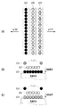
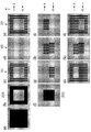
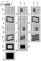
図6を用いて、それぞれの領域ごとに、データを記録ヘッド201、202、203に振り分けてデータの分配を行う工程について説明する。本図において、1マスは記録データ上の1画素を示しており、1画素に1つのインクドットが打ち込まれる。詳しくは後述するが、図6は記録ヘッド201〜203にデータを振り分けるための説明図であり、図6(c)、(g)、(j)は、記録ヘッド201に対応している。同様に、図6(d)、(h)、(k)は記録ヘッド202、図6(e)、(i)、(l)は記録ヘッド203に対応している。図6(a)は、本実施形態で記録される記録領域の記録データの全体について示した図である。図6(a)に示される記録対象領域は、外縁から所定の画素数だけ内側の領域である外周領域と、外周領域よりも内側の内部領域とを有している。図6(a)〜(l)の中央部横方向に示される点線は、記録ヘッドの走査方向が異なる領域の境界を示す。点線より上部は、記録ヘッドの走査方向がX方向(図6での右方向)の際に記録される画素であり、点線より下部は、記録ヘッドの走査方向が−X方向(図6での左方向)の際に記録される画素である。非エッジ部検出処理2001が行われると、2値化された記録データから、図6(f)に示す画素を形成するための非エッジ部データ2003と図6(b)に示す画素を形成するためのエッジ部データ2103が生成される。
A process of distributing data by distributing data to the recording heads 201, 202, and 203 for each area will be described with reference to FIG. In this figure, one square indicates one pixel on the recording data, and one ink dot is driven into one pixel. Although details will be described later, FIG. 6 is an explanatory diagram for distributing data to the recording heads 201 to 203, and FIGS. 6C, 6 G, and 6 J correspond to the
図6(b)〜(e)に示されるエッジ部データ2103の記録について説明する。図6(b)に示されるエッジ部データ2103は、緩浸透インクを吐出する記録ヘッド201及び203によって記録される。X方向への走査時には、記録ヘッド203が記録ヘッド201よりも走査方向の前方に位置する。従って、一回の走査で記録領域の記録を行いながら、図6(e)の上半分に示される画像が記録ヘッド203によって記録され、次いで同じ領域に対して、図6(c)の上半分に示される画像が記録ヘッド201によって記録される。X方向への走査が行われると、記録ヘッドの移動方向が折り返されて−X方向への走査が行われる。記録ヘッドの−X方向の走査時には、記録ヘッド201が記録ヘッド203よりも走査方向前方に位置している。従って、図6(c)の下半分に示される画像が記録ヘッド201によって記録され、次いで同じ領域に対して、図6(e)の下半分に示される画像が記録ヘッド203によって記録される。
The recording of the
次に、図6(f)〜(i)に示される非エッジ部データ2003の記録について説明する。図6(f)に、非エッジ部データ2003を示す。非エッジ部データ2003は、図6(a)に示される記録データ全体からエッジ部データ2103の部分を除いた領域の記録データである。
Next, recording of the
図6(f)の非エッジ部データ2003は、緩浸透インクを吐出する記録ヘッド201及び記録ヘッド203と、超浸透インクを吐出する記録ヘッド202との両方が用いられて記録が行われる。このとき、非エッジ部データ2003については、それぞれの記録領域で、記録される順序として、先に緩浸透インクによって記録された後に超浸透インクによる記録が行われる。
The
記録ヘッドがX方向へ走査する際には、図6(f)〜(i)の上半分の領域に対して記録が行われる。このとき、記録ヘッド203から緩浸透インクが吐出されると共に、記録ヘッド202から超浸透インクが吐出されて記録が行われる。このとき、記録ヘッド203は、記録ヘッド201よりも走査方向の前方に位置することになる。従って、一回の走査で記録領域の記録を行いながら、緩浸透インクを記録ヘッド203から所定領域に吐出し、続いてその部分に記録ヘッド202によって超浸透インクを吐出することが可能である。
When the recording head scans in the X direction, recording is performed on the upper half area of FIGS. At this time, the slow penetration ink is discharged from the
X方向への走査が行われると、記録ヘッドの移動方向が折り返されて−X方向への走査が行われる。−X方向へ記録ヘッドの走査が行われる際には、緩浸透インクを吐出する記録ヘッド201と、超浸透インクを吐出する記録ヘッド202が用いられて記録が行われる。このとき、記録ヘッド201は、記録ヘッド202よりも走査方向の前方に位置することになる。従って、−X方向への走査においても、一回の走査で記録領域の記録を行いながら、緩浸透インクを記録ヘッド201から所定領域に吐出し、続いてその部分に記録ヘッド202によって超浸透インクを吐出することができる。このように、図6(f)に示される非エッジ部データ2003のうちのX方向に走査する際に記録される上半分のデータは、超浸透インクを吐出する記録ヘッド202及び緩浸透インクを吐出する記録ヘッド203へ振り分けられる。このとき、記録ヘッド202へ振り分けられるデータは図6(h)の上半分であり、記録ヘッド203へ振り分けられるデータは図6(i)の上半分である。また、非エッジ部データ2003のうちの−X方向に走査する際に記録される下半分のデータは、緩浸透インクを吐出する記録ヘッド201及び超浸透インクを吐出する記録ヘッド202へ振り分けられる。同様に、記録ヘッド201に振り分けられるデータは図6(g)の下半分であり、記録ヘッド202へ振り分けられるデータは図6(h)の下半分である。
When scanning in the X direction is performed, the moving direction of the recording head is turned back and scanning in the -X direction is performed. When the recording head is scanned in the −X direction, recording is performed using the
以上から、それぞれの記録ヘッドが記録するデータは、以下の通りである。記録ヘッド201で記録するデータは、エッジ部データ図6(c)と非エッジ部データ図6(g)の論理和(図6(j))である。記録ヘッド202で記録するデータは、エッジ部データ図6(d)と非エッジ部データ図6(h)の論理和(図6(k))である。記録ヘッド203で記録するデータは、エッジ部データ図6(e)と非エッジ部データ図6(i)の論理和(図6(l))である。
From the above, the data recorded by each recording head is as follows. The data to be recorded by the
また、本発明には、上述のようなインクジェット記録方法により、記録媒体の記録対象領域に対しインクジェット記録装置によってインクを吐出させて記録を行う際に、インクジェット記録装置を制御させるプログラムが含まれる。 Further, the present invention includes a program for controlling an ink jet recording apparatus when recording is performed by ejecting ink to the recording target area of the recording medium by the ink jet recording apparatus by the above-described ink jet recording method.
本実施形態で使用されるインクの組成は次の通りである。なお、各成分の割合は質量部で示したものである(各成分の合計は100質量部)。 The composition of the ink used in this embodiment is as follows. In addition, the ratio of each component is shown by the mass part (the sum total of each component is 100 mass parts).
(超浸透インク)
顔料分散液 50質量部
グリセリン 10質量部
ポリエチレングリコール1000 1質量部
アセチレノールE100(川研ファインケミカル製) 1質量部
水 残部
(Super penetrating ink)
Pigment dispersion 50 parts by weight glycerin 10 parts by
(緩浸透インク)
顔料分散液 50質量部
グリセリン 10質量部
ポリエチレングリコール1000 1質量部
アセチレノールE100(川研ファインケミカル製) 0.03質量部
水 残部
また、上記顔料分散液は、次のようにして得たものである。
(Slow penetration ink)
Pigment dispersion liquid 50 parts by mass Glycerin 10 parts by
[顔料分散液]
表面積が230m2/gでDBP吸油量が70ml/100gのカーボンブラック10gとp−アミノ安息香酸3.41gとを水72gによく混合した後、これに硝酸1.62gを滴下して70℃で攪拌した。数分後5gの水に1.07gの亜硝酸ナトリウムを溶かした溶液を加え、更に1時間攪拌した。得られたスラリーを東洋濾紙No.2(アドバンティス社製)でろ過し、顔料粒子を十分に水洗し、90℃のオーブンで乾燥させた後、この顔料に水を足して顔料濃度10質量%の顔料水溶液を作成した。以上の方法により、表面にフェニル基を介して親水性基が結合したアニオン性に帯電した自己分散型カーボンブラックが分散した顔料分散液を得た。
[Pigment dispersion]
10 g of carbon black having a surface area of 230 m @ 2 / g and DBP oil absorption of 70 ml / 100 g and 3.41 g of p-aminobenzoic acid were mixed well with 72 g of water, and then 1.62 g of nitric acid was added dropwise thereto and stirred at 70.degree. did. Several minutes later, a solution prepared by dissolving 1.07 g of sodium nitrite in 5 g of water was added, and the mixture was further stirred for 1 hour. The obtained slurry was Toyo Filter Paper No. The mixture was filtered through 2 (manufactured by Advantis), the pigment particles were sufficiently washed with water and dried in an oven at 90 ° C., and water was added to the pigment to prepare an aqueous pigment solution having a pigment concentration of 10% by mass. By the above method, a pigment dispersion liquid in which an anionically charged self-dispersing carbon black having a hydrophilic group bonded to the surface via a phenyl group was dispersed was obtained.
本実施形態で採用したインク組成は、本発明が適用できる1例であり、同系色で、相対的な浸透性が異なる2つのインクを用いればよい。 The ink composition employed in the present embodiment is an example to which the present invention can be applied. Two inks having similar colors and different relative penetrabilities may be used.
本実施形態で用いた色材は自己分散型顔料と呼ばれるものであり、顔料粒子に親水基が付いたものである。一方で、樹脂分散型顔料と呼ばれる、顔料粒子に樹脂が付いており、その樹脂の親水基が水溶性を発揮するものもある。発明者らの検討によれば、本発明を適用するためには、より望ましくは自己分散型顔料を使用した方が良いが、樹脂分散型顔料でも発明の効果は得られた。 The color material used in the present embodiment is called a self-dispersing pigment, and has pigment groups with hydrophilic groups. On the other hand, there is also a resin called a resin dispersion type pigment in which a resin is attached to pigment particles and the hydrophilic group of the resin exhibits water solubility. According to the studies by the inventors, in order to apply the present invention, it is more desirable to use a self-dispersing pigment, but the effect of the invention was obtained even with a resin-dispersed pigment.
超浸透インクおよび緩浸透インクの浸透性の違いは、表面張力によって規定される。超浸透インクの表面張力は緩浸透インクの表面張力よりも小さく、かつ、超浸透インクの表面張力は20mN/m以上40mN/m以下、緩浸透インクの表面張力は40mN/m以上 60mN/m以下であれば、本発明の効果が得られた。表面張力を制御するために、本実施形態においては、アセチレノールE100(商品名;川研ファインケミカル社製)(エチレンオキサイド−2,4,7,9−テトラメチル−5−デシン−4,7−ジオール(ethylene oxide−2,4,7,9−tetramethyl−5−decyne−4,7−diol))という界面活性剤が用いられる。この界面活性剤によって、超浸透インクと緩浸透インクの浸透性を相対的に変化させているが、そのほかの溶剤によって変化させても良い。 The difference in permeability between super penetrating ink and slow penetrating ink is defined by the surface tension. The surface tension of the super-penetrating ink is smaller than the surface tension of the slow-penetrating ink, the surface tension of the super-penetrating ink is 20 mN / m or more and 40 mN / m or less, and the surface tension of the slow-penetrating ink is 40 mN / m or more and 60 mN / m or less. Then, the effect of the present invention was obtained. In order to control the surface tension, in this embodiment, acetylenol E100 (trade name; manufactured by Kawaken Fine Chemical Co., Ltd.) (ethylene oxide-2,4,7,9-tetramethyl-5-decyne-4,7-diol) (Ethylene oxide-2,4,7,9-tetramethyl-5-decyne-4,7-diol)) is used. This surfactant relatively changes the permeability of the super-penetrating ink and the slow-penetrating ink, but it may be changed by another solvent.
このように、外周領域(エッジ部)に対しては緩浸透インクによって記録を行うことで、記録画像の滲みが低減されて記録画像の品質の低下を抑えつつ、画像の濃度を上げることができる。また、内部領域(非エッジ部)に対しては、緩浸透インクに続いて超浸透インクで記録することで、超浸透インクの記録媒体内部への浸透の度合いを抑制させることができる。従って、記録媒体の表面にインクの色材を多く残留させることができるので、内部領域の光学濃度を上げることができる。また、緩浸透インクのみによって記録が行われる場合に比べて、インクの色材が記録媒体の表面から盛り上がって残ることが抑えられる。従って、記録媒体の表面よりも上方に残ったインクの色材が、ユーザーの手やその他のものに接触することによって記録画像が汚れ、記録画像の品質を低下させることを抑えることができる。このように、記録媒体の表面よりも上方に盛り上がって残るインクを低減させることで、記録画像の耐擦過性及び耐マーカー性を向上させることができる。 As described above, by performing recording on the outer peripheral region (edge portion) with the slowly penetrating ink, it is possible to increase the image density while suppressing the deterioration of the recorded image by reducing the bleeding of the recorded image. . Further, by recording the inner region (non-edge portion) with the super-penetrating ink subsequent to the slow-penetrating ink, the degree of permeation of the super-penetrating ink into the recording medium can be suppressed. Accordingly, a large amount of ink coloring material can remain on the surface of the recording medium, so that the optical density of the internal region can be increased. Further, it is possible to suppress the ink coloring material from rising and remaining from the surface of the recording medium as compared with the case where recording is performed using only the slowly penetrating ink. Accordingly, it is possible to prevent the ink coloring material remaining above the surface of the recording medium from coming into contact with the user's hand or other objects to contaminate the recorded image and reduce the quality of the recorded image. Thus, by reducing the ink that rises above the surface of the recording medium and remains, the scratch resistance and marker resistance of the recorded image can be improved.
(第二実施形態)
次に、本発明の第二実施形態に係るインクジェット記録装置による記録について説明する。なお、上記第一実施形態と同様に構成される部分については図中同一符号を付して説明を省略し、異なる部分についてのみ説明する。
(Second embodiment)
Next, recording by the ink jet recording apparatus according to the second embodiment of the present invention will be described. In addition, about the part comprised similarly to said 1st embodiment, the same code | symbol is attached | subjected in a figure, description is abbreviate | omitted, and only a different part is demonstrated.
第一実施形態では、エッジ部で緩浸透インクが打ち込まれると共に、非エッジ部の全てにおいて、先に緩浸透インクが打ち込まれ、その後に同一領域に対してインクを重ねるように超浸透インクが打ち込まれて記録が行われている。これに対して第二実施形態では、スループットを向上させるために、エッジ部及び非エッジ部で、一部のデータが間引かれて記録されている。そして、非エッジ部において、緩浸透インクにより記録されたドットと超浸透インクにより記録されたドットとが合わせられて互いに補完することで全体の記録画像が得られるように記録が行われている。本実施形態では、非エッジ部において、緩浸透インクによって記録された領域と超浸透インクによって記録された領域とが隣接するように記録が行われている。 In the first embodiment, the slowly penetrating ink is driven at the edge portion, and the slow penetrating ink is driven first in all the non-edge portions, and then the super penetrating ink is driven so as to overlap the ink in the same region. Recording has been done. On the other hand, in the second embodiment, in order to improve the throughput, a part of data is thinned and recorded at the edge portion and the non-edge portion. Then, in the non-edge portion, the recording is performed so that the dots recorded with the slowly penetrating ink and the dots recorded with the super penetrating ink are combined and complemented with each other to obtain an entire recorded image. In the present embodiment, the recording is performed so that the region recorded with the slow penetrating ink and the region recorded with the super penetrating ink are adjacent to each other at the non-edge portion.
個々の吐出口から連続的にインクを吐出する際には、インクの吐出を行うために記録素子に一旦エネルギーが加えられ、それから再度エネルギーが記録素子に加えられるのに一定の時間が必要となる。また、インクを吐出した後に、個々のノズルへインクを補給するためにインクのリフィル時間が必要となる。また、一定の時間ごとに、一定量の記録データを記憶領域に送信するための時間が必要になる。ここで、1回の走査で1つの記録ヘッドが記録可能なドットの数(以下、走査解像度とも言う)は、記録ヘッドの構成に強く依存する。記録ヘッドの構成を変えてその記録ヘッドの走査解像度を上げようとすると、記録ヘッドの構造を大きく変える必要があり、そこでコストアップをもたらしてしまう。 When ink is continuously ejected from the individual ejection ports, energy is temporarily applied to the recording element in order to eject ink, and then a certain amount of time is required for energy to be reapplied to the recording element. . Also, after ink is ejected, ink refill time is required to replenish ink to individual nozzles. Further, a certain amount of time is required for transmitting a certain amount of recording data to the storage area every certain time. Here, the number of dots that can be recorded by one recording head in one scan (hereinafter also referred to as scanning resolution) strongly depends on the configuration of the recording head. If an attempt is made to increase the scanning resolution of a recording head by changing the configuration of the recording head, the structure of the recording head needs to be greatly changed, which results in an increase in cost.
そこで、本実施形態では、1つの記録ヘッドが一回の走査で分担する記録ヘッドの走査方向(X方向又は−X方向)に関する記録可能なドットの数を、一つの記録ヘッドのみで記録する場合のn分の1としている。これだけではデータが欠落してしまうため、本実施形態では複数並べられた記録ヘッドに記録データを振り分けることにより、記録データを複数の記録ヘッドによって相互に補うこととしている。本実施形態では特に、1つの記録ヘッドが一回の走査で分担する記録ヘッドの走査方向に関する記録可能なドットの数を、一つの記録ヘッドのみで記録する場合の2分の1としている。そして、記録ヘッドのそれぞれにおける画素の数を、単一の記録ヘッドからインクを吐出することで形成される画素の数の2分の1としている。このように、本実施形態では、記録媒体に記録ヘッドからインクを吐出させる記録データを、それぞれの記録ヘッドに振り分けることで、一つの記録ヘッド当たりのインクの吐出数に対応する記録データの画素数を減少させている。 Therefore, in the present embodiment, the number of dots that can be recorded in the scanning direction (X direction or -X direction) of the recording head shared by one recording head in one scan is recorded by only one recording head. 1 / n. In this embodiment, recording data is distributed to a plurality of recording heads so that the recording data is supplemented by the plurality of recording heads. In the present embodiment, in particular, the number of dots that can be recorded in the scanning direction of the recording head shared by one recording head in one scan is one-half that when recording is performed with only one recording head. The number of pixels in each of the recording heads is set to one half of the number of pixels formed by ejecting ink from a single recording head. As described above, in this embodiment, the recording data for ejecting ink from the recording head to the recording medium is distributed to the respective recording heads, so that the number of pixels of the recording data corresponding to the number of ink ejections per recording head. Is decreasing.
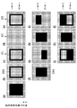
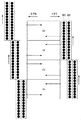
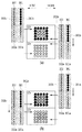
第二実施形態のフローでは、第一実施形態のフローと比較してエッジ処理以降が異なるので、図7および図8を用いてエッジ処理について説明する。ここで、2値化されたブラックデータについて、図8(a)に示す。図8(a)の中央部から横方向に示される点線は、記録ヘッドの走査方向が異なる領域の境界を示す。点線より上部は、記録ヘッドの走査方向がX方向(図8での右方向)のときに記録される画素であり、点線より下部は、記録ヘッドの走査方向が−X方向(図8での左方向)のときに記録される画素である。本実施形態では、記録ヘッド201、202、203における記録媒体の搬送方向に沿った長さは、図8(a)の縦方向の両端部の間の長さの半分であり、点線から縦方向の一方の端部までの長さである。 Since the flow of the second embodiment differs from the flow of the first embodiment after the edge processing, the edge processing will be described with reference to FIGS. 7 and 8. Here, the binarized black data is shown in FIG. A dotted line shown in the horizontal direction from the center of FIG. 8A indicates a boundary between regions where the scanning direction of the recording head is different. Above the dotted line is a pixel recorded when the scanning direction of the recording head is the X direction (right direction in FIG. 8), and below the dotted line, the scanning direction of the recording head is the −X direction (in FIG. 8). This is a pixel recorded in the (left direction). In the present embodiment, the length of the recording heads 201, 202, and 203 along the recording medium conveyance direction is half of the length between both ends in the vertical direction of FIG. It is the length to one edge part of.
また、詳しくは後述するが、図8は記録ヘッド201〜203にデータを振り分けるための説明図であり、図8(c)、(g)、(j)は、記録ヘッド201に対応している。同様に、図8(d)、(h)、(k)は記録ヘッド202に、図8(e)、(i)、(l)は記録ヘッド203に対応している。
Although details will be described later, FIG. 8 is an explanatory diagram for distributing data to the recording heads 201 to 203, and FIGS. 8C, 8 G, and 8 J correspond to the
まず、非エッジ部検出処理2001を行う。2値化されたブラックデータのうちの、内部領域のデータ、つまり、非エッジ部データ2003が生成される。2値ブラックデータのうちの、非エッジ部データに該当しなかったデータを、エッジ部データ2103とする。非エッジ部検出処理2001を行って得られた非エッジ部データ2003及びエッジ部データ2103について、図8(f)及び図8(b)に示す。本実施形態では、外周領域(エッジ部)の幅を2画素分とする。
First, non-edge
本実施形態のエッジ部データ2103は、そのデータのカラム位置に応じて、2つの記録ヘッドへ振り分けられる。エッジ部データ2103のうち奇数カラムのデータについては記録ヘッド201によって記録され、偶数カラムのデータについては記録ヘッド203によって記録される。ここでは、「奇数カラム」、「偶数カラム」とは、データにおけるカラムの位置について、左端部のカラムから奇数番目のカラムか偶数番目のカラムかのことを言うものとする。
The
非エッジ部データ2003においては、そのデータのカラム位置だけでなく、キャリッジ106及び記録ヘッド201〜206の走査方向に応じて、3つの記録ヘッドへデータが振り分けられる。非エッジ部への記録において走査方向がX方向である場合には、図8(h)、(i)に示されるように、奇数カラムのデータを記録ヘッド202、偶数カラムのデータを記録ヘッド203で記録する。走査方向が−X方向である場合には、図8(g)、(h)に示されるように、奇数カラムのデータを記録ヘッド201、偶数カラムのデータを記録ヘッド202で記録する。
In the
図8(b)のエッジ部データ2103を記録する場合には、そのカラム位置に応じて、図8(c)の奇数カラムのデータを記録ヘッド201によって記録し、図8(e)の偶数カラムのデータを記録ヘッド203で記録する。従って、エッジ部データ2103は、全て緩浸透インクによって記録される。
When the
図8(f)の非エッジ部データ2103の記録においては、走査方向がX方向(点線よりも上部の領域)の記録の際には、偶数カラムのデータを記録ヘッド203によってまず記録し、同じ走査で奇数カラムのデータを記録ヘッド202によって記録する。走査方向が−X方向(点線よりも下部の領域)の記録の際には、奇数カラムのデータを記録ヘッド201によって記録し、偶数カラムのデータを記録ヘッド202によって記録する。このように、走査方向の前方の記録ヘッドで緩浸透インクによる記録が行われ、それと同じ走査で走査方向の後方の記録ヘッドで超浸透インクによる記録が行われる。従って、先に緩浸透インクにより記録が行われ、その後に超浸透インクによる記録が行われる。
In the recording of the
非エッジ部データ2103の上部下部を合わせて、図8(g)〜(i)に示す。また、非エッジ部データ2103の記録において、記録ヘッド201で記録するデータを図8(g)に示し、記録ヘッド202で記録するデータを図8(h)に示し、記録ヘッド203で記録するデータを図8(i)に示す。以上から、第二実施形態において、それぞれの記録ヘッドが記録するデータは、以下の通りである。記録ヘッド201で記録するデータは、エッジ部データ図8(c)と非エッジ部データ図8(g)の論理和(図8(j))である。記録ヘッド202で記録するデータは、エッジ部データ図8(d)と非エッジ部データ図8(h)の論理和(図8(k))である。記録ヘッド203で記録するデータは、エッジ部データ図8(e)と非エッジ部データ図8(i)の論理和(図8(l))である。
The upper and lower portions of the
図8に示されるように、それぞれの記録ヘッド201〜203がそれぞれの走査で記録するデータは走査方向に関して間引かれており、第一実施形態と比較して、一回の走査で記録可能なデータのうちの半分のデータを記録する。このため、走査ごとの、記録データをデータ記憶領域に転送するデータ転送のための時間やインクのリフィル時間が半分で済むため、記録ヘッドの走査速度を2倍に上げることができる。例えば、走査解像度が1200dpiである構成をとった場合の走査速度が25ips(inches/second)である場合には、走査解像度を600dpiへ下げることができる。このため、記録ヘッドの走査速度を50ipsまで上げることが可能となり、記録にかかる時間も短くなる。従って、本実施形態の記録方法によって記録を行うことにより、記録ヘッドの走査速度を向上させることができるので、記録のスループットを向上させることができる。また、それと共に、内部領域の耐擦過性を向上させることができる。
As shown in FIG. 8, the data recorded by each
本実施形態では、非エッジ部(内部領域)に対して、先行して緩浸透インクを吐出し、カラム位置によって間引かれたデータを記録する。その後、緩浸透インクの吐出が間引かれた部分に対し、超浸透インクを吐出して記録する。このとき、緩浸透インクで記録される記録領域(第1の記録領域)と、超浸透インクで記録される記録領域(第2の記録領域)とが、少なくとも一部が接するように記録されている。緩浸透インクによって記録される記録領域と、超浸透インクによって記録される記録領域とが接することで、記録媒体表面で緩浸透インクと超浸透インクとが混合される。これにより、内部領域の耐擦過性及び耐マーカー性を向上させると共に、記録画像の光学濃度を増大させることができる。 In the present embodiment, the slowly penetrating ink is discharged in advance to the non-edge portion (inner region), and the data thinned out by the column position is recorded. Thereafter, the super-penetrating ink is discharged and recorded on the portion where the slow-penetrating ink is thinned. At this time, the recording area (first recording area) recorded with the slow-penetrating ink and the recording area (second recording area) recorded with the super-penetrating ink are recorded so as to be at least partially in contact with each other. Yes. The recording area recorded with the slow penetration ink and the recording area recorded with the super penetration ink come into contact with each other, so that the slow penetration ink and the super penetration ink are mixed on the surface of the recording medium. As a result, the scratch resistance and marker resistance of the internal region can be improved, and the optical density of the recorded image can be increased.
また、スループットの向上のために、X方向と−X方向の両方の双方向記録で、緩浸透インクの後に超浸透インクを吐出するのであれば、それぞれの方向への記録で緩浸透インクと超浸透インクとを吐出するための二つの記録ヘッドが必要である。従って、X方向への記録と、−X方向への記録との両方で、緩浸透インクを吐出した後に超浸透インクを吐出するためには、通常、合計4つの記録ヘッドが必要とされると考えられる。しかしながら、本実施形態のインクジェット記録装置における記録ヘッドの配置構成では、超浸透インクを吐出する記録ヘッドが一つ配置されているだけである。すなわち、X方向への走査の際の記録と、−X方向への走査の際の記録とで、超浸透インクを吐出する記録ヘッドを共用している。これにより、超浸透インクを吐出する記録ヘッドの個数を減少させ、インクジェット記録装置の構成を簡素化させている。これにより、インクジェット記録装置を小型化すると共に、インクジェット記録装置の製造コストを低く抑えることができる。 In addition, in order to improve the throughput, if the super-penetrating ink is ejected after the slow-penetrating ink in bidirectional recording in both the X direction and the -X direction, the super-penetrating ink and super-superimposed ink are recorded in each direction. Two recording heads for ejecting penetrating ink are required. Therefore, in order to eject the super-penetrating ink after ejecting the slowly penetrating ink in both the recording in the X direction and the recording in the −X direction, a total of four recording heads are usually required. Conceivable. However, in the arrangement configuration of the recording head in the ink jet recording apparatus of this embodiment, only one recording head that discharges the super-penetrating ink is arranged. That is, the recording head that discharges the super-penetrating ink is shared by the recording at the time of scanning in the X direction and the recording at the time of scanning in the -X direction. This reduces the number of recording heads that discharge super-penetrating ink and simplifies the configuration of the ink jet recording apparatus. Thereby, it is possible to reduce the size of the ink jet recording apparatus and reduce the manufacturing cost of the ink jet recording apparatus.
なお、本実施形態では、内部領域(非エッジ部)への記録において、最後続の記録ヘッド、すなわち−X方向への走査での記録ヘッド203、X方向への走査での記録ヘッド201からは、インクの吐出を行っていないが、本発明はこれに限定されない。最後続の記録ヘッドからインクの吐出を行う場合、耐擦過性及び耐マーカー性が低下する可能性があるが、それを許容できるのであれば、最後続の記録ヘッドからインクの吐出を行っても良い。その場合には、記録画像の光学濃度をさらに増加させることができる。最後続の記録ヘッドを用いて記録を行うかどうかについては、設計時に、記録装置の製品ごとに調整すれば良い。
In the present embodiment, in the recording to the internal region (non-edge portion), from the last recording head, that is, the
このように、本実施形態では、内部領域(非エッジ部)への記録において、緩浸透インク及び超浸透インクの記録を、カラムごとに分けて記録を行う。このとき、内部領域においては、記録媒体にインクが付与される際に、第一実施形態のように、緩浸透インクの上に超浸透インクが重ねられるように記録媒体上の同じ位置(画素)にインクの吐出が行われなくとも良く、異なる位置でもよい。本発明は、緩浸透インクが超浸透インクよりも先に内部領域に吐出されればよいため、記録媒体上で緩浸透インクのドットと超浸透インクのドットとが隣接するようにインクの吐出が行われれば良い。緩浸透インクのドットと超浸透インクのドットが、記録媒体上で少なくとも一部が重なるようにそれぞれの記録ヘッドからインクを吐出するためのデータを生成しても良い。このように記録が行われることでも本発明の効果を得ることができる。なお、本実施形態では、カラムごとに超浸透インクによって形成されるドットと緩浸透インクにより形成されるドットが使い分けられているが、本発明はこれに限定されない。超浸透インクによって形成されるドットと緩浸透インクにより形成されるドットが、千鳥格子状に分けられても良いし、その他の分け方が採用されても良い。 As described above, in the present embodiment, in the recording in the internal region (non-edge portion), the recording of the slowly penetrating ink and the super penetrating ink is performed separately for each column. At this time, in the internal region, when ink is applied to the recording medium, as in the first embodiment, the same position (pixel) on the recording medium so that the super-penetrating ink is superimposed on the slow-penetrating ink. Further, the ink does not have to be ejected, and may be at a different position. According to the present invention, since the slow penetration ink only needs to be ejected to the internal region before the super penetration ink, the ink is ejected so that the slow penetration ink dot and the super penetration ink dot are adjacent to each other on the recording medium. It only has to be done. Data for ejecting ink from each recording head may be generated so that the dots of the slowly penetrating ink and the dots of the super penetrating ink overlap at least partially on the recording medium. The effect of the present invention can also be obtained by recording in this way. In this embodiment, the dots formed by the super-penetrating ink and the dots formed by the slow osmotic ink are separately used for each column, but the present invention is not limited to this. Dots formed by super-penetrating ink and dots formed by slow-penetrating ink may be divided into a staggered pattern, or other division methods may be employed.
(第三実施形態)
次に、本発明の第三実施形態に係るインクジェット記録装置による記録について説明する。なお、上記第一実施形態及び第二実施形態と同様に構成される部分については図中同一符号を付して説明を省略し、異なる部分についてのみ説明する。
(Third embodiment)
Next, recording by the ink jet recording apparatus according to the third embodiment of the present invention will be described. In addition, about the part comprised similarly to said 1st embodiment and 2nd embodiment, the same code | symbol is attached | subjected in a figure, description is abbreviate | omitted, and only a different part is demonstrated.
第一実施形態及び第二実施形態では、外周の縁部から1画素もしくは2画素の幅を記録領域におけるエッジ部として記録画像を形成している。これに対して本実施形態では、エッジ部として4画素が選択されて記録を行う。図9を用いて、それぞれのデータの記録ヘッドへの分配について説明する。 In the first embodiment and the second embodiment, a recorded image is formed with the width of one pixel or two pixels from the outer peripheral edge as the edge in the recording area. In contrast, in the present embodiment, recording is performed with four pixels selected as the edge portion. The distribution of each data to the recording head will be described with reference to FIG.
画像の記録がより高解像度になると、エッジ部の幅(以下、エッジ画素数と呼ぶ)もそれに応じてより増加させた方が望ましい。エッジ画素数は、解像度によっておおよそ決定される記録ヘッドからのインクの吐出量に依存する。例えば、600×600dpiの解像度でインクの吐出を行う記録ヘッドによって画像を形成する場合には、記録ヘッドから吐出するインクの量(すなわち吐出量)として、15〜30pl程度のインク吐出量が選択されて記録装置が設計されることが多い。この場合の普通紙でのドット径は、60μm程度であることが多い。 As the image recording becomes higher resolution, it is desirable to increase the width of the edge portion (hereinafter referred to as the number of edge pixels) accordingly. The number of edge pixels depends on the amount of ink ejected from the recording head, which is roughly determined by the resolution. For example, when an image is formed by a recording head that ejects ink at a resolution of 600 × 600 dpi, an ink ejection amount of about 15 to 30 pl is selected as the amount of ink ejected from the recording head (ie, ejection amount). Recording devices are often designed. In this case, the dot diameter of plain paper is often about 60 μm.
また、例えば1200×1200dpiの解像度でインクの吐出を行うことのできる記録ヘッドによって画像を形成する場合には、記録ヘッドから吐出するインクの量(すなわち吐出量)として、4〜15pl程度が選択されて記録装置が設計されることが多い。この場合、記録媒体上に吐出されたインクによるドット径は、普通紙上で30μm程度であることが多い。 For example, when an image is formed by a recording head capable of ejecting ink at a resolution of 1200 × 1200 dpi, about 4 to 15 pl is selected as the amount of ink ejected from the recording head (that is, the ejection amount). Recording devices are often designed. In this case, the dot diameter of the ink ejected on the recording medium is often about 30 μm on plain paper.
内部領域のインクが外周領域を超えて記録したい画像よりもはみ出ることは望ましくない。そのため、緩浸透インクによって形成された外周領域がある程度の幅を有していることが好ましい。内部領域の外側にある程度の幅を有する外周領域が形成されていることで、内部領域に吐出される超浸透インクによる滲みが外周領域を超えて、外周領域の外側にはみ出すことが抑えられる。解像度が高くなっても、超浸透インクによる滲みが外周領域を超えないように、外周領域の幅が保たれることが望ましい。上述の例の600×600dpiと1200×1200dpiとの解像度の記録の例で考慮すると、600×600dpiの場合にエッジ画素数が十分であれば、1200×1200dpiでのエッジ画素数は600×600dpiの場合の2倍程度であれば良い。このように解像度に応じて画素数を選択することで、外周領域(エッジ部)の幅が保たれ、外周領域を超える内部領域からの超浸透インクによる滲みを抑えることができる。そのため、記録画像の品質の低下を抑えることができる。このように、エッジ部の領域の幅(外周領域の幅)が内部領域に打ち込まれる超浸透インクと外部領域に打ち込まれる緩浸透インクの浸透性の差によって決められ、画素数は解像度に応じて決定されることが望ましい。そのため、記録ヘッドによるインク吐出の解像度が高解像度に設定されている場合には、それに応じてエッジ部を形成する画素数を増加させることが望ましい。 It is not desirable that the ink in the inner area protrude beyond the image to be recorded beyond the outer peripheral area. For this reason, it is preferable that the outer peripheral region formed by the slowly penetrating ink has a certain width. By forming the outer peripheral region having a certain width outside the inner region, it is possible to suppress the bleeding due to the super-penetrating ink discharged to the inner region from exceeding the outer peripheral region and to the outside of the outer peripheral region. Even if the resolution is increased, it is desirable to maintain the width of the outer peripheral region so that bleeding due to the super-penetrating ink does not exceed the outer peripheral region. Considering the example of recording with resolutions of 600 × 600 dpi and 1200 × 1200 dpi in the above example, if the number of edge pixels is sufficient in the case of 600 × 600 dpi, the number of edge pixels at 1200 × 1200 dpi is 600 × 600 dpi. It may be about twice as much as the case. Thus, by selecting the number of pixels according to the resolution, the width of the outer peripheral region (edge portion) is maintained, and bleeding due to the super-penetrating ink from the inner region exceeding the outer peripheral region can be suppressed. For this reason, it is possible to suppress a decrease in the quality of the recorded image. As described above, the width of the edge region (the width of the outer peripheral region) is determined by the difference in permeability between the super-penetrating ink driven into the inner region and the slow-penetrating ink driven into the outer region, and the number of pixels depends on the resolution. It is desirable to be determined. Therefore, when the resolution of ink ejection by the recording head is set to a high resolution, it is desirable to increase the number of pixels forming the edge portion accordingly.
(第四実施形態)
次に、本発明の第四実施形態に係るインクジェット記録装置による記録について説明する。なお、上記第一実施形態ないし第三実施形態と同様に構成される部分については図中同一符号を付して説明を省略し、異なる部分についてのみ説明する。
(Fourth embodiment)
Next, recording by the ink jet recording apparatus according to the fourth embodiment of the present invention will be described. In addition, about the part comprised similarly to said 1st embodiment thru | or 3rd embodiment, the same code | symbol is attached | subjected in a figure, description is abbreviate | omitted, and only a different part is demonstrated.
第一実施形態ないし第三実施形態における記録装置では、緩浸透インクを吐出する二つの記録ヘッドと、超浸透インクを吐出する一つの記録ヘッドとの計三つの記録ヘッドが用いられて記録が行われている。これに対して本実施形態における記録装置では、緩浸透インクを吐出する一つの記録ヘッドと、超浸透インクを吐出する一つの記録ヘッドとの計二つの記録ヘッドのみを用いて記録を行う。本実施形態では、第一実施形態ないし第三実施形態の記録ヘッドと比較して若干スループットが落ちるが、記録ヘッドの数が少なくて済むため、記録装置のコストを低減させることができる。 In the recording apparatus according to the first to third embodiments, recording is performed by using a total of three recording heads, that is, two recording heads that discharge the slow-penetrating ink and one recording head that discharges the super-penetrating ink. It has been broken. On the other hand, in the recording apparatus according to the present embodiment, recording is performed using only two recording heads, that is, one recording head that discharges the slowly penetrating ink and one recording head that discharges the super-penetrating ink. In this embodiment, the throughput is slightly lower than that of the recording heads of the first to third embodiments, but the number of recording heads can be reduced, so that the cost of the recording apparatus can be reduced.
以下、本実施形態に係る記録装置の記録ヘッド301〜305について説明する。本実施形態の記録ヘッド301〜305は、それぞれ5つのインク(ブラック(緩浸透インク)、ブラック(超浸透インク)、シアン、マゼンタ、イエロー:Ke、Km、Ke、C、M、Y)を吐出可能に構成されている。記録ヘッド301〜305のうち、ブラックのインクを吐出する記録ヘッドは、記録ヘッド301、302である。さらにこれらのブラックのインクを吐出する記録ヘッドのうち、記録ヘッド301が、比較的記録媒体に浸透しにくい緩浸透インクを吐出する。また、記録ヘッド302が、比較的記録媒体に浸透しやすい超浸透インクを吐出する。
Hereinafter, the recording heads 301 to 305 of the recording apparatus according to the present embodiment will be described. Each of the recording heads 301 to 305 of the present embodiment ejects five inks (black (slow penetrating ink), black (super penetrating ink), cyan, magenta, yellow: Ke, Km, Ke, C, M, and Y). It is configured to be possible. Among the recording heads 301 to 305, the recording heads that discharge black ink are the recording heads 301 and 302. Further, among the recording heads that discharge these black inks, the
また、説明のため、記録ヘッド301、302を記録媒体の搬送方向に2分割し、領域ごとにインクを吐出する2パス記録の形態を用いて説明する。記録ヘッド301の上半分(記録媒体の搬送方向の上流側)を301aとし、下半分(記録媒体の搬送方向の下流側)を301b、記録ヘッド302の上半分を302a、下半分を302bとする。
For the sake of explanation, the recording heads 301 and 302 are divided into two in the conveyance direction of the recording medium, and a two-pass recording mode in which ink is ejected for each region will be described. The upper half of the recording head 301 (upstream in the conveyance direction of the recording medium) is 301a, the lower half (downstream of the recording medium in the conveyance direction) is 301b, the upper half of the
ここで、走査開始方向という判断基準について説明する。例えば本実施形態の記録装置が2パス双方向記録の形式である場合には、記録ヘッドの一回の走査が終わるごとに、記録ヘッドが記録できる幅の半分の距離だけ、記録媒体を搬送する。記録媒体を固定して考えた方が理解し易いので、記録媒体を固定として、図11を用いて説明する。 Here, the criteria for determining the scanning start direction will be described. For example, when the recording apparatus of the present embodiment is a two-pass bidirectional recording format, the recording medium is transported by a distance that is half the width that can be recorded by the recording head every time scanning of the recording head is completed. . Since it is easier to understand if the recording medium is fixed, the description will be given with reference to FIG. 11 assuming that the recording medium is fixed.
本実施形態では、同一の記録対象領域に対して記録ヘッドが複数回走査することで記録対象領域上を複数回通過し、その度にインクの吐出が行われ、複数回の走査によって画像が記録されるマルチパス方式のインクジェット記録装置を用いている。本実施形態の2パス記録では、記録ヘッドが同一の記録対象領域に対して2回の走査を行うことで画像を記録する。 In the present embodiment, the recording head scans the same recording target region a plurality of times so that the recording head region passes a plurality of times, and ink is ejected each time, and an image is recorded by the plurality of scanning operations. The multi-pass inkjet recording apparatus is used. In the two-pass printing according to the present embodiment, the print head scans the same print target area twice to print an image.
また、本実施形態では、記録ヘッドに形成された複数の吐出口が、複数の領域に区画されている。記録媒体の搬送方向に沿って区画された半分の吐出口が一回目の走査で記録対象領域上を通過し、二回目の走査で残りの吐出口が記録対象領域上を通過する。そのため、二回の走査で記録対象領域の画像の記録が完成する。この記録対象領域における画像のうち、内部領域に対しては、先に緩浸透インクを吐出する記録ヘッドに形成された複数の吐出口のうち、区画された一部の吐出口からインクを吐出して記録が行われる(第3の記録シーケンス)。そして、その後に、超浸透インクを吐出する記録ヘッドに形成された複数の吐出口のうち、区画された一部の吐出口からインクを吐出して記録が行われる(第4の記録シーケンス)。 In the present embodiment, a plurality of ejection openings formed in the recording head are partitioned into a plurality of regions. Half of the ejection openings defined along the recording medium conveyance direction pass over the recording target area in the first scan, and the remaining ejection openings pass over the recording target area in the second scanning. For this reason, the recording of the image of the recording target area is completed by two scans. Among the images in the recording target area, ink is ejected from a part of the plurality of ejection openings formed in the recording head that ejects the slowly penetrating ink to the internal area. Recording is performed (third recording sequence). After that, recording is performed by ejecting ink from some of the partitioned ejection openings formed in the recording head that ejects the super-penetrating ink (fourth recording sequence).
記録ヘッドをX方向に走査させて領域(1)を記録した後、記録媒体を搬送させて、その後、記録ヘッドを−X方向に走査させて領域(1)および(2)を記録する。それから再び記録媒体を搬送し、記録ヘッドをX方向に走査して領域(2)および(3)を記録する。これらの走査と記録媒体の搬送とを繰り返すことで、画像データを記録媒体へ記録する。 After the recording head is scanned in the X direction to record the area (1), the recording medium is conveyed, and then the recording head is scanned in the −X direction to record the areas (1) and (2). Then, the recording medium is conveyed again, and the recording head is scanned in the X direction to record the areas (2) and (3). By repeating these scans and conveyance of the recording medium, the image data is recorded on the recording medium.
ここで、領域(1)に着目すると、記録ヘッドのX方向の走査による記録に引き続いて、−X方向の走査による記録が行われる。また、領域(2)に着目すると、記録ヘッドの−X方向の走査による記録に引き続いて、X方向の走査による記録が行われる。すなわち、記録媒体に対して最初に記録が行われるときの記録ヘッドの走査方向は、記録媒体上の領域によって異なる。領域(1)や(3)のように、最初に記録が行われる際の記録ヘッドの走査方向がX方向である場合、本明細書上では、「走査開始方向がX方向である」と表現する。同様に、領域(2)や(4)のように、最初に記録が行われる際の記録ヘッドの走査方向が−X方向である場合、本明細書上では、「走査開始方向が−X方向である」と表現する。 Here, focusing on the area (1), recording by scanning in the −X direction is performed following recording by scanning in the X direction of the recording head. Focusing on the area (2), recording by scanning in the X direction is performed following recording by scanning in the −X direction of the recording head. That is, the scanning direction of the recording head when recording is first performed on the recording medium differs depending on the area on the recording medium. When the scanning direction of the recording head when recording is first performed is the X direction as in the areas (1) and (3), it is expressed as “the scanning start direction is the X direction” in this specification. To do. Similarly, as in the areas (2) and (4), when the scanning direction of the recording head when recording is first performed is the −X direction, in this specification, “the scanning start direction is the −X direction”. It is expressed.
ここで図10を参照して、記録媒体にインクを付与する順序について説明する。図10(a)に記録ヘッド301〜305のうちブラックのインクを吐出する記録ヘッド301、302を示す。このうち、記録ヘッド301は緩浸透インクを吐出する記録ヘッドであり、記録ヘッド302は超浸透インクを吐出する記録ヘッドである。図10(b)、(c)にそれぞれの記録ヘッドからインクを吐出する順序について示す。図10(b)は−X方向への走査によって記録が開始された記録領域のインクが付与される順序について示されている。また、図10(c)はX方向への走査によって記録が開始された記録領域のインクが付与される順序について示されている。
Now, with reference to FIG. 10, the order of applying ink to the recording medium will be described. FIG. 10A shows recording heads 301 and 302 that discharge black ink among the recording heads 301 to 305. Among these, the
図10(b)を用いて、記録媒体における走査開始方向が−X方向である領域に対する記録について説明する。一回目の走査で、内部領域と外周領域に記録ヘッド301aから緩浸透インク311aを吐出すると共に、内部領域に記録ヘッド302aから超浸透インク312aを吐出する。一回の走査を終えると、記録媒体が所定距離搬送され、そこで走査方向が切り替わり、記録ヘッド301〜305はX方向へ走査しながらインクの吐出を行う。記録ヘッドがX方向へ走査を行う際には、外周領域に対し、記録ヘッド301bによって緩浸透インク311bの吐出を行いながら記録が行われる。
With reference to FIG. 10B, recording in an area where the scanning start direction on the recording medium is the −X direction will be described. In the first scan, the slowly penetrating
次に、図10(c)を用いて、記録媒体における走査開始方向がX方向である領域に対する記録について説明する。一回目の走査で、内部領域と外周領域に記録ヘッド301aから緩浸透インク321aを吐出する。一回の走査が終わると、記録媒体が所定距離搬送され、そこで走査方向が切り替わり、記録ヘッドが−X方向に走査しながらインクの吐出を行う。記録ヘッドが−X方向へ走査を行う際には、外周領域に記録ヘッド301bから緩浸透インク321bを吐出すると共に、内部領域に記録ヘッド302bから超浸透インク322bを吐出する。本実施形態では、緩浸透インクを吐出する記録ヘッド301bは、外周領域のみにインクの吐出を行い、超浸透インクを吐出する記録ヘッド302a、302bは、内部領域にのみインクの吐出を行う。
Next, with reference to FIG. 10C, recording in an area where the scanning start direction in the recording medium is the X direction will be described. In the first scan, the slowly penetrating
次に、2値化されたブラックデータについて行われるエッジ処理について説明する。図12に、エッジ処理の工程の図を示す。まず、非エッジ部検出処理5001を行う。2値化されたブラックデータのうちの、非エッジ部のデータ、つまり、非エッジ部データ5003が生成される。2値化されたブラックデータのうちの、非エッジ部データに該当しなかったデータを、エッジ部データ5103とする。本実施形態では、エッジ画素として、2画素を選択する。本実施形態では、記録ヘッドの走査開始方向に応じて、データをそれぞれの記録ヘッドに分配する。
Next, edge processing performed on the binarized black data will be described. FIG. 12 shows a diagram of the edge processing steps. First, non-edge
エッジ部データ5103は、記録ヘッド走査開始方向がX方向の領域であれば、奇数カラムのデータは記録ヘッド301aで記録し、偶数カラムのデータは記録ヘッド301bで記録する。記録ヘッド走査開始方向が−X方向の領域であれば、奇数カラムのデータは記録ヘッド301bで記録し、偶数カラムのデータは記録ヘッド301aで記録する。
In the
非エッジ部データ5003は、記録ヘッドの走査開始方向がX方向の領域であれば、奇数カラムのデータは記録ヘッド301aで記録し、偶数カラムのデータは記録ヘッド302bで記録する。記録ヘッドの走査開始方向が−X方向の領域であれば、奇数カラムのデータは記録ヘッド302aで記録し、偶数カラムのデータは記録ヘッド301aで記録する。
In the
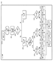
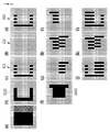
図13を用いて、これらの関係を説明する。前述の実施形態と同様に、図13(c)、(h)、(l)は、記録ヘッド301aに対応している。同様に、図13(d)、(i)、(m)は記録ヘッド302aに、図13(e)、(j)、(n)は記録ヘッド301bに、図13(f)、(k)、(o)は記録ヘッド302bに対応している。
These relationships will be described with reference to FIG. As in the above-described embodiment, FIGS. 13C, 13H, and 13 correspond to the
2値化されたブラックデータにより記録媒体に打ち込まれる画素について図13(a)に示す。図13(a)から中央部横方向に延びるように示される点線は、記録ヘッドの走査開始方向が変化する位置を示す。 FIG. 13A shows a pixel driven into a recording medium by binarized black data. A dotted line shown so as to extend in the horizontal direction from the center in FIG. 13A indicates a position where the scanning start direction of the recording head changes.
点線より上部は、図11での領域(1)や(3)のような記録ヘッドの走査開始方向がX方向(図13での右方向)の領域であり、点線より下部は、図11での領域(2)や(4)のような記録ヘッドの走査開始方向が−X方向(図13での左方向)の領域である。記録データは、非エッジ部検出処理2001が行われて、非エッジ部データ5003とエッジ部データ5103が生成される。
The area above the dotted line is an area where the scanning start direction of the recording head is the X direction (right direction in FIG. 13) as in areas (1) and (3) in FIG. 11, and the area below the dotted line is in FIG. The scanning start direction of the recording head as in the areas (2) and (4) is the area in the −X direction (left direction in FIG. 13). The recording data undergoes non-edge
図13(b)に、図13(a)に示される2値化されたブラックデータのうち、エッジ部データ5103について示す。エッジ部データ5103のうち、記録ヘッドの走査開始方向がX方向の領域(点線より上部)であれば、奇数カラムのデータは記録ヘッド301aに振り分けられて記録される(図13(c))。また、エッジ部データ5103のうち、記録ヘッドの走査開始方向がX方向の領域における偶数カラムのデータは記録ヘッド301bに振り分けられて記録される(図13(e))。エッジ部データ5103のうち、記録ヘッドの走査開始方向が−X方向の領域(点線より下部)であれば、奇数カラムのデータは記録ヘッド301bに振り分けられて記録される(図13(e))。また、エッジ部データ5103のうち、記録ヘッドの走査開始方向が−X方向の領域における偶数カラムのデータは記録ヘッド301aに振り分けられて記録される(図13(c))。
FIG. 13B shows
図13(g)に、図13(a)に示される2値化されたブラックデータのうち、非エッジ部データ5003について示す。図13(g)に示される非エッジ部データ5003のうち、記録ヘッドの走査開始方向がX方向の領域(点線より上部)における、奇数カラムのデータについては記録ヘッド301aに振り分けられる。そして、記録ヘッド301aに振り分けられたデータに応じて、記録ヘッド301aによって記録される(図13(h))。また、非エッジ部データ5003のうち、記録ヘッドの走査開始方向がX方向の領域における、偶数カラムのデータについては記録ヘッド302bに振り分けられ、記録ヘッド302bによって記録される(図13(k))。
FIG. 13G shows
また、非エッジ部データ5003のうち、記録ヘッドの走査開始方向が−X方向の領域(点線より下部)であれば、奇数カラムのデータについては記録ヘッド302aに振り分けられて記録される(図13(i))。非エッジ部データ5003のうち、記録ヘッドの走査開始方向が−X方向の領域における偶数カラムのデータについては、記録ヘッド301aに振り分けられて記録される(図13(h))。
Further, in the
以上から、それぞれの記録ヘッドが記録するデータは、以下の通りである。記録ヘッド301aによって記録されるデータは、エッジ部データ図13(c)と非エッジ部データ図13(h)との論理和の図13(l)である。記録ヘッド302aによって記録されるデータは、エッジ部データ図13(d)と非エッジ部データ図13(i)との論理和の図13(m)である。また、記録ヘッド301bによって記録されるデータは、エッジ部データ図13(e)と非エッジ部データ図13(j)との論理和の図13(n)である。また、記録ヘッド302bによって記録されるデータは、エッジ部データ図13(f)と非エッジ部データ図13(k)との論理和の図13(o)である。
From the above, the data recorded by each recording head is as follows. The data recorded by the
図13に示されるように、それぞれの記録ヘッド301、302によって記録されるデータは主走査方向(図1のX方向、図13での横方向)に関して間引かれており、一回の走査につき、記録されるデータのうちの半分のデータについての記録が行われる。このため、一回の走査で全ての記録データについての記録が行われる場合に比べて記録ヘッドへのデータ転送にかかる時間やリフィル時間が半分で済む。そのため、記録ヘッドの主走査速度を2倍に上げることができる。例えば、記録ヘッドの走査解像度が1200dpiである構成をとった場合の主走査速度が25ipsである場合には、一回の走査で記録される記録データが間引かれることで記録されるドット数が600dpiに下げることができる。これにより、記録ヘッドの主走査速度を50ipsまで上げることが可能となる。このため、記録全体にかかる時間が短縮化され、記録のスループットが向上する。 As shown in FIG. 13, the data recorded by the respective recording heads 301 and 302 are thinned out in the main scanning direction (the X direction in FIG. 1 and the horizontal direction in FIG. 13). Recording is performed for half of the data to be recorded. For this reason, the time required for data transfer to the recording head and the refilling time are halved compared to the case where all the recording data is recorded in one scan. Therefore, the main scanning speed of the recording head can be doubled. For example, when the main scanning speed when the scanning resolution of the recording head is 1200 dpi is 25 ips, the number of dots to be recorded is reduced by thinning out the recording data recorded in one scan. It can be lowered to 600 dpi. As a result, the main scanning speed of the recording head can be increased to 50 ips. For this reason, the time required for the entire recording is shortened, and the recording throughput is improved.
図14を参照してさらに説明する。図14(a)及び図14(b)において、走査開始方向は、領域(1)及び領域(3)ではX方向、領域(2)では−X方向である。本実施形態では、走査開始方向がX方向か−X方向かに関わらず、外周領域(エッジ部)への記録においては、記録ヘッド301aからのインクの吐出に引き続いて記録ヘッド301bからインクの吐出を行う。記録ヘッド301a及び記録ヘッド301bの両方の記録ヘッドからインクの吐出を行って記録が行われることで、一回の走査で記録されるドット数を低減させても、その分をお互いの記録ヘッドからのインクの吐出によって補完できる。内部領域への記録においては、全ての領域で記録ヘッド301aから緩浸透インクの吐出が行われる。ここでの記録では、データの半分が間引かれており、記録ヘッド301aからのインクの吐出によって記録されなかった部分について補完するために、他の記録ヘッドによってインクの吐出が行われる。
This will be further described with reference to FIG. 14A and 14B, the scanning start direction is the X direction in the region (1) and the region (3), and the −X direction in the region (2). In the present embodiment, regardless of whether the scanning start direction is the X direction or the −X direction, in the recording on the outer peripheral area (edge portion), the ink is ejected from the
図14(a)の領域(1)に示されるように、走査開始方向が−X方向である場合には、記録ヘッド301aからのインクの吐出が行われる走査と同一の走査のときに記録ヘッド302aからのインクの吐出によって記録が行われる。このとき、記録ヘッド302aは、記録ヘッド301aよりも走査方向の後方に位置しているので、記録ヘッド301aからの緩浸透インクによるインクの吐出が行われてから、記録ヘッド302aからの超浸透インクによるインクの吐出が行われる。そのため、記録媒体へのインクの吐出が行われる順序としては、緩浸透インクによるインクの吐出が行われた後に超浸透インクによるインクの吐出が行われる。
As shown in the area (1) of FIG. 14A, when the scanning start direction is the −X direction, the recording head is in the same scanning as the scanning in which ink is ejected from the
また、図14(a)、(b)に示されるように、走査開始方向がX方向である場合には、一回目の走査での記録の際に、記録ヘッド302aからのインクの吐出は行われずに、記録ヘッド301aからのインクの吐出が行われる。走査開始方向がX方向である場合に、記録ヘッド302aからのインクの吐出によって記録が行われないのは、記録ヘッド301aから緩浸透インクを記録する以前に、超浸透インクを吐出する記録ヘッド302aが記録対象領域を通過してしまうからである。すなわち、このような場合には、本発明の構成要件であるところの、緩浸透インクに続いての超浸透インクによる記録を行うことができない。
Further, as shown in FIGS. 14A and 14B, when the scanning start direction is the X direction, ink is ejected from the
記録ヘッド301aからのインクの吐出による記録が行われ、一回の走査を終えると、走査方向が切り替えられて−X方向に走査する。このとき、図14(b)の領域(2)に示されるように、内部領域では記録ヘッド302bによって超浸透インクによるインクの吐出が行われて記録が行われる。
Recording is performed by ejecting ink from the
このように、走査開始方向がX方向であっても−X方向であっても、記録ヘッド302a、302bから吐出される超浸透インクは、先行して記録されている緩浸透インクの後に記録される。本実施形態において、先に吐出されている緩浸透インクのドットと、後から吐出される超浸透インクのドットとは、記録データ上で重複あるいは隣接しており、それぞれの記録データが少なくとも相互に接している。 In this way, regardless of whether the scanning start direction is the X direction or the −X direction, the super-penetrating ink ejected from the recording heads 302a and 302b is recorded after the previously recorded slow-penetrating ink. The In the present embodiment, the dots of the slowly penetrating ink ejected first and the dots of the super penetrating ink ejected later overlap or are adjacent on the recording data, and the respective recording data are at least mutually. It touches.
このとき、緩浸透インクは浸透速度が相対的に遅いインクであるから、記録ヘッド302a、302bから吐出される超浸透インクが記録媒体表面に着弾するまで、記録媒体表面に留まっている。緩浸透インクと超浸透インクがお互いに接することで、それぞれが混合されて両者の浸透速度が平均化される。すなわち、緩浸透インクのみで記録した箇所よりも、浸透速度が速くなる。このように、画像の内部領域(非エッジ部)の一部に対して、浸透速度が遅いインクの後に浸透速度が速いインクを用いて記録を行うことにより、浸透速度が遅い緩浸透インクのみで記録する場合よりも耐擦過性を向上させることができる。 At this time, since the slowly penetrating ink is a relatively slow penetrating ink, it stays on the surface of the recording medium until the super-penetrating ink ejected from the recording heads 302a and 302b lands on the surface of the recording medium. When the slowly penetrating ink and the super penetrating ink are in contact with each other, they are mixed and the permeation speed of both is averaged. That is, the permeation speed is faster than the portion recorded with only the slow permeation ink. In this way, by recording on a part of the inner area (non-edge portion) of the image using an ink with a low penetration speed followed by an ink with a high penetration speed, only a slow penetration ink with a low penetration speed can be used. The scratch resistance can be improved as compared with the case of recording.
また、さらに記録ヘッド301bから吐出した緩浸透インクは、記録ヘッド301aによって先行して記録されている緩浸透インクの上へ記録される。このとき緩浸透インクは浸透速度が遅いインクであるから、最後続の記録ヘッドから吐出されるインクが記録媒体表面に着弾するまで、記録媒体表面に留まっている。緩浸透インクと緩浸透インクが記録媒体表面で混合しても、浸透速度は速くはならず、遅い浸透速度のインクが2滴記録されただけである。画像の外周領域(エッジ部)に、浸透速度が遅いインクで記録することにより、画像端部のシャープネスを向上させることができ、文字品位や線品位が向上する。また、内部領域へ緩浸透インクに続いて超浸透インクで記録することで、超浸透インクのみによって記録が行われる場合と比較して内部領域の光学濃度を増大させることができる。
Further, the slowly penetrating ink discharged from the
以上説明したように、本実施形態では、緩浸透インクを吐出する記録ヘッドと超浸透インクを吐出する記録ヘッドとのそれぞれの記録ヘッドについて、記録ヘッドを複数の領域に分割している。これにより、それぞれの記録ヘッドに形成された複数の吐出口が複数の領域に区画される。そして、内部領域への記録においては、緩浸透インクを吐出する記録ヘッドのうちの一部の領域が先に記録対象領域上を通過し、その後超浸透インクを吐出する記録ヘッドの一部が記録対象領域上を通過する。それぞれの記録ヘッドが記録領域上を通過するときにインクを記録領域に吐出することで記録が行われる。 As described above, in the present embodiment, the recording head is divided into a plurality of regions for each of the recording head that discharges the slowly penetrating ink and the recording head that discharges the super-penetrating ink. Thereby, a plurality of ejection openings formed in each recording head are partitioned into a plurality of regions. In recording to the internal area, a part of the recording head that discharges the slowly penetrating ink first passes over the recording target area, and then a part of the recording head that discharges the super penetrating ink records. Pass over the target area. Recording is performed by ejecting ink to the recording area when each recording head passes over the recording area.
記録ヘッドが走査を行いながら走査方向に関わらず記録対象領域に緩浸透インクを先に吐出し、その後記録対象領域に超浸透インクを吐出する場合には、通常、記録ヘッドが4つ必要とされると考えられる。しかしながら、第四実施形態では複数回の走査によって記録画像が形成されるマルチパス形式の記録装置が用いられ、それぞれの記録ヘッドに形成された複数の吐出口が複数の領域に区画されている。そして、記録ヘッドの走査方向に関わらず、緩浸透インクを吐出する記録ヘッドの一部によって記録対象領域を記録した後に、超浸透インクを吐出する記録ヘッドの一部によって記録対象領域を記録することが可能に形成されている。 When the recording head performs scanning, the slow penetrating ink is first ejected to the recording target area regardless of the scanning direction, and then the super penetrating ink is ejected to the recording target area, usually four recording heads are required. It is thought. However, in the fourth embodiment, a multi-pass printing apparatus that forms a print image by a plurality of scans is used, and a plurality of ejection openings formed in each print head are partitioned into a plurality of regions. Then, regardless of the scanning direction of the recording head, after the recording target area is recorded by a part of the recording head that discharges the slowly penetrating ink, the recording target area is recorded by a part of the recording head that discharges the super-penetrating ink. Is made possible.
このように、本実施形態では、緩浸透インクを吐出する一つの記録ヘッドと、超浸透インクを吐出する一つの記録ヘッドとの計二つの記録ヘッドを用いて記録を行う。第一実施形態ないし第三実施形態の記録ヘッドに比較して若干スループットが低下するが、記録ヘッドの数が少なくて済むため、記録装置のコストを低減させることができる。 As described above, in the present embodiment, recording is performed using a total of two recording heads, that is, one recording head that discharges the slowly penetrating ink and one recording head that discharges the super-penetrating ink. Although the throughput is slightly reduced as compared with the recording heads of the first to third embodiments, since the number of recording heads is small, the cost of the recording apparatus can be reduced.
なお、緩浸透インクを吐出する記録ヘッドと超浸透インクを吐出する記録ヘッドとのそれぞれの記録ヘッドにおいて、複数の吐出口が二つの領域に区分されて分割されることとしたが、本発明はこれに限定されない。緩浸透インクを吐出する記録ヘッドと超浸透インクを吐出する記録ヘッドのそれぞれが、二つ以上の領域に分割されたとしても良い。このとき、緩浸透インクを吐出した後に超浸透インクを吐出するように順序が定められるのであれば、それぞれの記録ヘッドの領域の分割は二つでなくとも良い。また、本実施形態では2パス記録の例を用いて説明したが、本実施形態はこれに限るものではなく、3パス記録や4パス記録のような場合であってもよい。この場合も、記録対象領域に対する1走査目の記録において、先に緩浸透インクを吐出し、その後に超浸透インクを吐出するように記録ヘッドを制御すればよい。 In each recording head of the recording head that discharges the slowly penetrating ink and the recording head that discharges the super-penetrating ink, the plurality of discharge ports are divided into two regions and divided. It is not limited to this. Each of the recording head that discharges the slowly penetrating ink and the recording head that discharges the super penetrating ink may be divided into two or more regions. At this time, if the order is determined so that the super-penetrating ink is ejected after the slow-penetrating ink is ejected, the division of the area of each recording head may not be two. Further, although the present embodiment has been described by using an example of two-pass printing, the present embodiment is not limited to this and may be a case such as three-pass printing or four-pass printing. In this case as well, the recording head may be controlled so that the slowly penetrating ink is discharged first and then the super penetrating ink is discharged in the first scan of the recording target area.
(第五実施形態)
次に、本発明の第五実施形態に係るインクジェット記録装置による記録について説明する。なお、上記第一実施形態ないし第四実施形態と同様に構成される部分については図中同一符号を付して説明を省略し、異なる部分についてのみ説明する。
(Fifth embodiment)
Next, recording by the ink jet recording apparatus according to the fifth embodiment of the present invention will be described. In addition, about the part comprised similarly to said 1st embodiment thru | or 4th embodiment, the same code | symbol is attached | subjected in a figure, description is abbreviate | omitted, and only a different part is demonstrated.
上述した第一実施形態ないし第四実施形態では、記録ヘッドから吐出されるインクの種類としてブラックのみが吐出される例について説明した。第五実施形態では、カラーインクによる記録と並行してブラックインクによる記録が行われる場合について説明する。 In the first to fourth embodiments described above, the example in which only black is ejected as the type of ink ejected from the recording head has been described. In the fifth embodiment, a case where recording with black ink is performed in parallel with recording with color ink will be described.
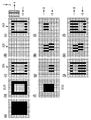
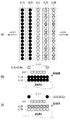
カラーインクによって記録された画像とブラックインクによって記録された画像とがお互いに隣接して記録される場合には、それぞれの画像が隣接している部分については、エッジ部として記録するのではなく非エッジ部として記録を行う方が良いことが多い。カラー画像の記録と並行してブラックインクの記録を行う場合の、記録データの生成方法について図15に示す。 When the image recorded with the color ink and the image recorded with the black ink are recorded adjacent to each other, the portion where each image is adjacent is not recorded as an edge portion but is not recorded. It is often better to record as an edge. FIG. 15 shows a method for generating recording data when black ink recording is performed in parallel with color image recording.
図15(a)において、斜線部はカラー画像のデータであり、黒塗り部は図8(a)と同様に、ブラックインクにより記録される部分の2値化された記録データである。図15(b)にエッジ部データ2103について示し、図15(f)に非エッジ部データ2003について示す。第二実施形態の図8と比較すると、図15(b)に示されるように、カラーインクによる記録される記録データと隣接している部分において、ブラック単独のデータではエッジと考えられていた部分の一部(右端部)が非エッジ部としてデータ生成されている。
In FIG. 15A, the shaded portion is color image data, and the blacked portion is binarized recording data of a portion recorded with black ink, as in FIG. 8A. FIG. 15B shows the
また、カラーの緩浸透インクとブラックの緩浸透インクとで記録媒体への浸透性ついて比較したときにカラーインクの浸透性の方が高い場合には、ブラックインクにおける相対的な浸透性をより高くした方が望ましい。そのような場合には、記録媒体に浸透しなかったブラックインクがカラーインクによって記録される部分のインクに混じり、ブラックインクがカラーインクによって記録される領域に流れ出してしまう可能性がある。そのため、ブラックインクとカラーインクとが隣接する領域でブラックインクによる記録対象領域を緩浸透インクのみで記録すると、記録画像の品質が低下する可能性がある。このような事態が発生することを防ぐために、ブラックインクの記録領域とカラーインクの記録領域とが隣接している場合には、ブラックインクにおける相対的な浸透性をより高くした方が画像品位が向上すると考えられる。 Also, if the color ink has a higher permeability when compared with the color slow penetration ink and the black slow penetration ink, the relative permeability in the black ink is higher. It is better to do it. In such a case, there is a possibility that the black ink that has not penetrated into the recording medium is mixed with the ink in the portion recorded with the color ink, and the black ink flows out to the area recorded with the color ink. For this reason, if the black ink and the color ink are adjacent to each other and the area to be recorded with the black ink is recorded with only the slowly penetrating ink, the quality of the recorded image may be deteriorated. In order to prevent such a situation from occurring, when the black ink recording area and the color ink recording area are adjacent to each other, the image quality is improved by increasing the relative permeability of the black ink. It is thought to improve.
(第六実施形態)
次に、本発明の第六実施形態に係るインクジェット記録装置による記録について説明する。なお、上記第一実施形態ないし第五実施形態と同様に構成される部分については図中同一符号を付して説明を省略し、異なる部分についてのみ説明する。
(Sixth embodiment)
Next, recording by the ink jet recording apparatus according to the sixth embodiment of the present invention will be described. In addition, about the part comprised similarly to said 1st embodiment thru | or 5th embodiment, the same code | symbol is attached | subjected in a figure, description is abbreviate | omitted, and only a different part is demonstrated.
第二実施形態ないし第五実施形態では、記録データを複数の記録ヘッドに振り分けることで、1つの記録ヘッドが分担する一回の走査での記録の際の走査方向(主走査方向)に関する記録可能なデータ上のドット数をデータ記録解像度の2分の1とした。こうすることで、記録ヘッドの走査速度を増大させ、記録の際のスループットを向上させている。これに加え、本実施形態では、緩浸透インクを吐出するための記録ヘッドの個数を増加させることで1つの記録ヘッドが分担する記録ヘッドの主走査方向(X方向)における記録すべきドット数をさらに減少させている。これにより、記録ヘッドの走査速度をさらに向上させ、記録のスループットを向上させることができる。 In the second embodiment to the fifth embodiment, printing data can be recorded with respect to the scanning direction (main scanning direction) at the time of printing in one scan shared by one printing head by distributing printing data to a plurality of printing heads. The number of dots on the correct data was set to one half of the data recording resolution. By doing so, the scanning speed of the recording head is increased, and the throughput during recording is improved. In addition to this, in this embodiment, the number of dots to be recorded in the main scanning direction (X direction) of the recording head shared by one recording head is increased by increasing the number of recording heads for discharging the slowly penetrating ink. It is further reduced. Thereby, the scanning speed of the recording head can be further improved, and the recording throughput can be improved.
図16を用いて、記録ヘッドの構成と、インクの付与順序について説明する本実施形態では、記録ヘッドを計5つ用いている。超浸透インクを吐出する記録ヘッド412を挟むように、緩浸透インクを吐出する記録ヘッド411L、411R、413L、413Rが、記録ヘッド412の両側部に配置されている。本実施形態では、記録ヘッド412の図16における左側に記録ヘッド411L、411Rが配置され、記録ヘッド412の図16における右側に記録ヘッド413L、413Rが配置されている。
In this embodiment, which describes the configuration of the recording head and the ink application sequence with reference to FIG. 16, a total of five recording heads are used. The recording heads 411L, 411R, 413L, and 413R that discharge slowly penetrating ink are disposed on both sides of the
本実施形態の記録装置によって記録されるときには、内部領域(非エッジ部)へは、先に緩浸透インクを吐出する2つの記録ヘッドによるインクの吐出が行われる。このとき、記録ヘッドの走査方向がX方向であれば記録ヘッド413R及び記録ヘッド413Lが用いられ、−X方向であれば411L及び記録ヘッド411Rが用いられる。そして、その後に、記録ヘッド412から超浸透インクを吐出して記録を行う。また、外周領域への記録においては、緩浸透インクを吐出する記録ヘッドのうち走査方向の後方に配置された記録ヘッド(X方向であれば411Rもしくは411L、−X方向であれば413Lもしくは413R)からインクを吐出して記録を行う。
When recording is performed by the recording apparatus of the present embodiment, ink is ejected into the internal region (non-edge portion) by the two recording heads that eject the slowly penetrating ink first. At this time, if the scanning direction of the recording head is the X direction, the
(第七実施形態)
次に、本発明の第七実施形態に係るインクジェット記録装置による記録について説明する。なお、上記第一実施形態ないし第六実施形態と同様に構成される部分については図中同一符号を付して説明を省略し、異なる部分についてのみ説明する。
(Seventh embodiment)
Next, recording by the ink jet recording apparatus according to the seventh embodiment of the present invention will be described. In addition, about the part comprised similarly to said 1st embodiment thru | or 6th embodiment, the same code | symbol is attached | subjected in a figure, description is abbreviate | omitted, and only a different part is demonstrated.
本実施形態では、緩浸透インクの色材濃度を、超浸透インクの色材濃度よりも薄くすることとする。記録画像の外周領域においては、緩浸透インクのみが記録されることになる。そのため、記録媒体の表面を越えて盛り上がった部分が発生し易い。そのような部分においては、記録媒体上の色材が指等に対して接触し、記録画像が汚れ、記録画像の品質が低下する可能性がある。また、マーカーによって画像上をなぞったときに、色材がマーカーによって汚され、記録画像の品質が低下する可能性がある。 In the present embodiment, the color material concentration of the slowly penetrating ink is made thinner than the color material concentration of the super penetrating ink. Only the slowly penetrating ink is recorded in the outer peripheral area of the recorded image. Therefore, a portion that rises beyond the surface of the recording medium is likely to occur. In such a portion, there is a possibility that the color material on the recording medium comes into contact with the finger or the like, the recorded image becomes dirty, and the quality of the recorded image is deteriorated. Further, when the image is traced with the marker, the color material may be stained with the marker, and the quality of the recorded image may be deteriorated.
従って、外周領域において記録媒体の表面よりも色材が盛り上がることを防ぐために、本実施形態では外周領域へ記録する緩浸透インクの色材濃度を減少させている。これにより、記録画像における外周部分の耐マーカー性や擦過性を向上させることができる。本実施形態で使用したインクの組成は次に示す通りである。なお、各成分の割合は質量部で示したものである(各成分の合計は100質量部)。 Therefore, in order to prevent the color material from rising above the surface of the recording medium in the outer peripheral area, the color material concentration of the slowly penetrating ink recorded in the outer peripheral area is reduced in this embodiment. Thereby, the marker resistance and scratch resistance of the outer peripheral portion in the recorded image can be improved. The composition of the ink used in this embodiment is as follows. In addition, the ratio of each component is shown by the mass part (the sum total of each component is 100 mass parts).
(緩浸透インク2)
顔料分散液 20質量部
グリセリン 10質量部
ポリエチレングリコール1000 1質量部
アセチレノールE100(川研ファインケミカル製) 0.03質量部
水 残部
(Slow penetration ink 2)
Pigment dispersion 20 parts by weight glycerin 10 parts by
(第八実施形態)
次に、本発明の第八実施形態に係るインクジェット記録装置による記録について説明する。なお、上記第一実施形態ないし第七実施形態と同様に構成される部分については図中同一符号を付して説明を省略し、異なる部分についてのみ説明する。
(Eighth embodiment)
Next, recording by the ink jet recording apparatus according to the eighth embodiment of the present invention will be described. In addition, about the part comprised similarly to said 1st embodiment thru | or 7th embodiment, the same code | symbol is attached | subjected in a figure, description is abbreviate | omitted, and only a different part is demonstrated.
本実施形態では、第七実施形態のインク組成によって形成されたインクを採用しつつ、ブラックインクによる記録とカラーインクによる記録とが並行して行われる場合について説明する。第五実施形態で説明したように、ブラックインクによって記録される領域とカラーインクによって記録される領域とが隣接している場合には、それらの領域が接している部分については、エッジ部とせずに非エッジ部とする方が良いことが多い。本実施形態においても、ブラックインクによって記録される領域とカラーインクによって記録される領域とが接している部分については、エッジ部とせずに非エッジ部として記録し、緩浸透インクだけでなく超浸透インクも用いて記録を行う。 In the present embodiment, a case where recording with black ink and recording with color ink are performed in parallel while employing the ink formed by the ink composition of the seventh embodiment will be described. As described in the fifth embodiment, when an area recorded with black ink and an area recorded with color ink are adjacent to each other, the portion in contact with these areas is not an edge portion. It is often better to use a non-edge portion. Also in the present embodiment, the portion where the region recorded with the black ink and the region recorded with the color ink are in contact is recorded as a non-edge portion instead of an edge portion. Recording is also performed using ink.
(第九実施形態)
次に、本発明の第九実施形態に係るインクジェット記録装置による記録について説明する。なお、上記第一実施形態ないし第八実施形態と同様に構成される部分については図中同一符号を付して説明を省略し、異なる部分についてのみ説明する。
(Ninth embodiment)
Next, recording by the ink jet recording apparatus according to the ninth embodiment of the present invention will be described. In addition, about the part comprised similarly to said 1st embodiment thru | or 8th embodiment, the same code | symbol is attached | subjected in a figure, description is abbreviate | omitted, and only a different part is demonstrated.
本実施形態においても、第七実施形態のインク組成によって形成されたインクを採用しつつ、ブラックインクによる記録とカラーインクによる記録とが並行して行われる場合について説明する。第五実施形態及び第八実施形態のように、ブラックインクによって記録される領域とカラーインクによって記録される領域とが隣接している場合には、それらの領域が接している部分については、エッジ部とせずに非エッジ部とする方が良いことが多い。 In the present embodiment as well, a case will be described in which the black ink recording and the color ink recording are performed in parallel while employing the ink formed by the ink composition of the seventh embodiment. As in the fifth embodiment and the eighth embodiment, when an area recorded with black ink and an area recorded with color ink are adjacent to each other, an edge is in contact with a portion where these areas are in contact with each other. It is often better to use a non-edge part instead of a part.
しかしながら、本実施形態のように色材濃度が低い緩浸透インクを用いた記録装置においては、ブラックインクによって記録される領域とカラーインクによって記録される領域とが隣接しているかどうかを判定する機能が省略されても良い。通常、ブラックインクの記録領域とカラーインクの記録領域とが隣接している部分において、ブラックインクによって記録される領域のエッジ部へ緩浸透インクを用いて記録が行われると、緩浸透インクがブラック側からカラー側へにじみ出す場合がある。そのため、ブラックインクのキレが低下する場合が生じることが多い。しかしながら、本実施形態のように、色材濃度が低い緩浸透インクが用いられた場合には、カラーインク側にブラックインクが滲み出した場合に記録画像の品質の低下が目立ち難い。従って、ブラックインクがカラーインクに滲み出した場合の記録画像の品質の低下を抑えることができる。 However, in the recording apparatus using the slowly penetrating ink having a low color material density as in the present embodiment, the function of determining whether the area recorded by the black ink and the area recorded by the color ink are adjacent to each other. May be omitted. Normally, when recording is performed using the slowly penetrating ink at the edge portion of the area where the black ink recording area and the color ink recording area are adjacent to each other, the slowly penetrating ink is black. It may ooze from the side to the color side. For this reason, the sharpness of the black ink often decreases. However, as in the present embodiment, when a slowly penetrating ink having a low color material density is used, when the black ink oozes out to the color ink side, it is difficult to notice a decrease in the quality of the recorded image. Therefore, it is possible to suppress the deterioration of the recorded image quality when the black ink oozes into the color ink.
(他の実施形態)
なお、上述の実施形態では、同系色のインクとしてブラックインクについて緩浸透インクと超浸透インクとを用いて記録を行う例について説明した。この同系色のインクとは、色材濃度が異なっていてもよく、前述したように緩浸透インクの色材濃度が超浸透インクの色材濃度よりも低くなっていることが好ましい。また、本発明は上述の実施形態に限定されず、他の色についても緩浸透インクと超浸透インクとを用いて記録を行うこととしても良い。このとき、緩浸透インクによる記録が行われた後に超浸透インクによる記録が行われるようにすれば良い。
(Other embodiments)
In the above-described embodiment, an example has been described in which recording is performed using a slowly penetrating ink and a super penetrating ink for a black ink as a similar color ink. The same color ink may have a different color material concentration, and as described above, the color material concentration of the slowly penetrating ink is preferably lower than the color material concentration of the super-penetrating ink. Further, the present invention is not limited to the above-described embodiment, and recording may be performed for other colors using the slowly penetrating ink and the super penetrating ink. At this time, the recording with the super-penetrating ink may be performed after the recording with the slowly penetrating ink.
また、上述の実施形態では、双方向記録を行う場合について説明したが、本発明はこれに限るものではなく、双方向記録よりもスループットが低下することを考慮すれば、片方向記録でもよい。この場合、緩浸透インクを吐出する記録ヘッドが、超浸透インクを吐出する記録ヘッドよりも走査方向前方に位置する構成であれば、内部領域に対して超浸透インクよりも緩浸透インクを先に吐出することができるため、本発明の効果を得ることができる。 Further, in the above-described embodiment, the case where bidirectional recording is performed has been described. However, the present invention is not limited to this, and unidirectional recording may be performed considering that the throughput is lower than that of bidirectional recording. In this case, if the recording head that discharges the slowly penetrating ink is positioned in front of the recording head that discharges the super penetrating ink in the scanning direction, the slow penetrating ink is put in front of the super penetrating ink in the internal region. Since it can discharge, the effect of this invention can be acquired.
また、上述の実施形態は、記録媒体に対して記録ヘッドが走査して記録を行う例を用いて説明したが、本発明はこれに限るものではなく、記録ヘッドと記録媒体の相対走査により記録が行われるものであればよい。すなわち、記録ヘッドに対して記録媒体が移動するものであってもよい。また、本発明は、上述の実施形態のように記録ヘッドをインク色毎に備える形態に限るものではなく、インクを吐出する吐出口列をインク色ごとに有する1つまたは複数の記録ヘッドの形態であってもよい。 Further, although the above-described embodiment has been described using an example in which the recording head scans the recording medium and performs recording, the present invention is not limited to this, and recording is performed by relative scanning of the recording head and the recording medium. As long as the is performed. That is, the recording medium may move relative to the recording head. In addition, the present invention is not limited to the form in which the recording head is provided for each ink color as in the above-described embodiment, but the form of one or a plurality of recording heads having an ejection port array for ejecting ink for each ink color. It may be.
また、本明細書において、「記録」とは、文字、図形等有意の情報を形成する場合のみならず、有意無意を問わずに用いられる。また、人間が視覚で知覚し得るように顕在化したものであるか否かを問わず、広く記録媒体上に画像、模様、パターン等を形成する、または記録媒体の加工を行う場合も表すものとする。 Further, in this specification, “recording” is used not only for forming significant information such as characters and figures but also regardless of significance. It also represents the case where images, patterns, patterns, etc. are widely formed on a recording medium, or the recording medium is processed, regardless of whether it is manifested so that it can be perceived by human eyes. And
また、「記録装置」とは、プリンタ、プリンタ複合機、複写機、ファクシミリ装置などのプリント機能を有する装置、ならびにインクジェット技術を用いて物品の製造を行なう製造装置を含む。 The “recording device” includes a device having a printing function such as a printer, a printer multifunction device, a copying machine, and a facsimile device, and a manufacturing device that manufactures an article using an ink jet technique.
また、「記録媒体」とは、一般的な記録装置で用いられる紙のみならず、広く、布、プラスチック・フィルム、金属板、ガラス、セラミックス、木材、皮革等、インクを受容可能なものを表すものとする。 “Recording medium” means not only paper used in general recording apparatuses but also a wide range of materials that can accept ink, such as cloth, plastic film, metal plate, glass, ceramics, wood, leather, etc. Shall.
さらに、「インク」(「液体」と言う場合もある)とは、上記「記録」の定義と同様広く解釈されるべきものである。記録媒体上に付与されることによって、画像、模様、パターン等の形成または記録媒体の加工、或いはインクの処理(例えば記録媒体に付与されるインク中の色材の凝固または不溶化)に供され得る液体を表すものとする。 Furthermore, “ink” (sometimes referred to as “liquid”) should be interpreted widely as in the definition of “recording”. By being applied on the recording medium, it can be used for formation of images, patterns, patterns, etc., processing of the recording medium, or ink processing (for example, solidification or insolubilization of the coloring material in the ink applied to the recording medium). It shall represent a liquid.
201、202、203、301、302、401L、401R、402、403L、403R 記録ヘッド
2103、5103 エッジ部データ
2003、5003 非エッジ部データ
201, 202, 203, 301, 302, 401L, 401R, 402, 403L,
Claims (11)
前記記録媒体において、記録が行われない非記録領域と隣接する外周領域に対して前記第2のインクを用いずに前記第1のインクを用いて記録を行い、前記外周領域と隣接する内部領域に対して前記第1のインクと前記第2のインクを用い、かつ、前記第1のインクを前記第2のインクよりも先に前記内部領域に吐出して記録を行うように、前記記録ヘッドからのインクの吐出を制御する記録制御手段
を備えることを特徴とするインクジェット記録装置。 By causing the recording head capable of ejecting the first ink and the second ink having the same color as the first ink and having a higher permeability than the first ink to scan relative to the recording medium. An inkjet recording apparatus for recording an image on the recording medium,
In the recording medium, recording is performed using the first ink without using the second ink on an outer peripheral area adjacent to a non-recording area where no recording is performed, and an inner area adjacent to the outer peripheral area. The recording head uses the first ink and the second ink, and discharges the first ink to the internal region before the second ink for recording. An ink jet recording apparatus comprising: a recording control unit that controls ejection of ink from the ink.
前記記録制御手段は、前記複数回の走査のうち前記所定領域に対して前記第1のインク及び第2のインクを用いて記録を行う最初の走査では、前記内部領域に対して前記第1のインクを前記第2のインクよりも先に前記内部領域に吐出して記録を行うように、前記記録ヘッドからのインクの吐出を制御することを特徴とする請求項1に記載のインクジェット記録装置。 The recording head performs recording by scanning a predetermined area of the recording medium a plurality of times,
In the first scan in which the first ink and the second ink are recorded on the predetermined area in the plurality of scans, the recording control unit performs the first scan on the inner area. 2. The ink jet recording apparatus according to claim 1, wherein ejection of ink from the recording head is controlled so that ink is ejected to the internal region before the second ink and recording is performed.
前記記録媒体において、記録が行われない非記録領域と隣接する外周領域に対して前記第2のインクを用いずに前記第1のインクを用いて記録を行い、前記外周領域と隣接する内部領域に対して前記第1のインクと前記第2のインクを用い、かつ、前記第1のインクを前記第2のインクよりも先に前記内部領域に吐出して記録を行うように、前記記録ヘッドからのインクの吐出を制御する記録制御工程
を備えることを特徴とするインクジェット記録方法。 By causing the recording head capable of ejecting the first ink and the second ink having the same color as the first ink and having a higher permeability than the first ink to scan relative to the recording medium. An inkjet recording method for recording an image on the recording medium,
In the recording medium, recording is performed using the first ink without using the second ink on an outer peripheral area adjacent to a non-recording area where no recording is performed, and an inner area adjacent to the outer peripheral area. The recording head uses the first ink and the second ink, and discharges the first ink to the internal region before the second ink for recording. An ink jet recording method comprising: a recording control step for controlling ejection of ink from the ink.
Priority Applications (5)
| Application Number | Priority Date | Filing Date | Title |
|---|---|---|---|
| JP2010163890A JP5791242B2 (en) | 2010-07-21 | 2010-07-21 | Inkjet recording apparatus, inkjet recording method, and inkjet recording head |
| US13/183,604 US8740336B2 (en) | 2010-07-21 | 2011-07-15 | Ink jet printing apparatus and ink jet printing method |
| CN201110199734.3A CN102343712B (en) | 2010-07-21 | 2011-07-18 | Ink jet printing apparatus and ink jet printing method |
| EP11005960.7A EP2409843B1 (en) | 2010-07-21 | 2011-07-20 | Ink jet printing apparatus and ink jet printing method |
| RU2011130377/12A RU2505415C2 (en) | 2010-07-21 | 2011-07-20 | Ink jet printing device and method of ink jet |
Applications Claiming Priority (1)
| Application Number | Priority Date | Filing Date | Title |
|---|---|---|---|
| JP2010163890A JP5791242B2 (en) | 2010-07-21 | 2010-07-21 | Inkjet recording apparatus, inkjet recording method, and inkjet recording head |
Publications (3)
| Publication Number | Publication Date |
|---|---|
| JP2012024970A true JP2012024970A (en) | 2012-02-09 |
| JP2012024970A5 JP2012024970A5 (en) | 2013-09-05 |
| JP5791242B2 JP5791242B2 (en) | 2015-10-07 |
Family
ID=44545422
Family Applications (1)
| Application Number | Title | Priority Date | Filing Date |
|---|---|---|---|
| JP2010163890A Active JP5791242B2 (en) | 2010-07-21 | 2010-07-21 | Inkjet recording apparatus, inkjet recording method, and inkjet recording head |
Country Status (5)
| Country | Link |
|---|---|
| US (1) | US8740336B2 (en) |
| EP (1) | EP2409843B1 (en) |
| JP (1) | JP5791242B2 (en) |
| CN (1) | CN102343712B (en) |
| RU (1) | RU2505415C2 (en) |
Cited By (1)
| Publication number | Priority date | Publication date | Assignee | Title |
|---|---|---|---|---|
| JP2013166368A (en) * | 2012-01-20 | 2013-08-29 | Canon Inc | Image processing method and image processing apparatus |
Families Citing this family (8)
| Publication number | Priority date | Publication date | Assignee | Title |
|---|---|---|---|---|
| US12330178B2 (en) | 2012-12-27 | 2025-06-17 | Kateeva, Inc. | Techniques for arrayed printing of a permanent layer with improved speed and accuracy |
| KR20190123811A (en) | 2012-12-27 | 2019-11-01 | 카티바, 인크. | Techniques for print ink volume control to deposit fluids within precise tolerances |
| US11673155B2 (en) | 2012-12-27 | 2023-06-13 | Kateeva, Inc. | Techniques for arrayed printing of a permanent layer with improved speed and accuracy |
| KR102034420B1 (en) | 2013-12-12 | 2019-11-08 | 카티바, 인크. | Ink-based layer fabrication using halftoning to control thickness |
| JP6593622B2 (en) * | 2015-03-20 | 2019-10-23 | セイコーエプソン株式会社 | Recording device |
| JP2020015225A (en) * | 2018-07-25 | 2020-01-30 | キヤノン株式会社 | Recording device and recording method |
| US11642880B2 (en) * | 2020-09-14 | 2023-05-09 | Assa Abloy Ab | Ink jet printer overspray techniques |
| CN117460624B (en) * | 2021-06-04 | 2026-02-27 | 惠普发展公司,有限责任合伙企业 | Printing system for producing optimized images |
Citations (5)
| Publication number | Priority date | Publication date | Assignee | Title |
|---|---|---|---|---|
| JPH07149036A (en) * | 1993-08-26 | 1995-06-13 | Fuji Xerox Co Ltd | Ink jet recording method, color image processing method, color image processor, ink jet recorder |
| JPH08281975A (en) * | 1995-02-13 | 1996-10-29 | Canon Inc | Inkjet head, inkjet cartridge, printing apparatus, and inkjet printing method |
| JPH08295034A (en) * | 1995-04-27 | 1996-11-12 | Canon Inc | Color recorder |
| JP2002113850A (en) * | 2000-10-06 | 2002-04-16 | Fuji Xerox Co Ltd | Ink jet recorder |
| JP2009234273A (en) * | 2009-07-14 | 2009-10-15 | Canon Inc | Inkjet recorder and recording head |
Family Cites Families (12)
| Publication number | Priority date | Publication date | Assignee | Title |
|---|---|---|---|---|
| US5568169A (en) | 1994-10-19 | 1996-10-22 | Xerox Corporation | Method and apparatus using two different black inks to reduce intercolor bleeding and provide high quality edge definition with thermal ink jet systems |
| JP3320292B2 (en) | 1995-02-13 | 2002-09-03 | キヤノン株式会社 | INK JET PRINTING APPARATUS AND INK JET PRINTING METHOD |
| JPH10100452A (en) | 1996-09-28 | 1998-04-21 | Seiko Epson Corp | Ink jet recording device |
| JP4683585B2 (en) * | 1999-09-17 | 2011-05-18 | キヤノン株式会社 | Ink set |
| JP4194226B2 (en) | 2000-06-27 | 2008-12-10 | キヤノン株式会社 | Ink jet recording apparatus and image data correction method |
| US6805422B2 (en) | 2000-06-27 | 2004-10-19 | Canon Kabushiki Kaisha | Ink jet recording method, recording apparatus and data processing method |
| JP2003220693A (en) * | 2002-01-29 | 2003-08-05 | Fuji Xerox Co Ltd | Image forming method and image forming apparatus |
| JP2004291627A (en) | 2003-03-11 | 2004-10-21 | Canon Inc | Ink jet recording apparatus and ink recording method |
| JP4315207B2 (en) | 2007-03-08 | 2009-08-19 | セイコーエプソン株式会社 | Printing control device, printing device |
| US7988277B2 (en) | 2007-05-11 | 2011-08-02 | Canon Kabushiki Kaisha | Ink set, ink jet recording method, ink cartridge, recording unit, ink jet recording method, and aqueous ink |
| JP5932199B2 (en) | 2007-05-11 | 2016-06-08 | キヤノン株式会社 | Ink set, ink jet recording method, ink cartridge, recording unit, ink jet recording method, and water-based ink |
| JP5164826B2 (en) | 2008-12-25 | 2013-03-21 | キヤノン株式会社 | Image processing apparatus and image processing method |
-
2010
- 2010-07-21 JP JP2010163890A patent/JP5791242B2/en active Active
-
2011
- 2011-07-15 US US13/183,604 patent/US8740336B2/en active Active
- 2011-07-18 CN CN201110199734.3A patent/CN102343712B/en active Active
- 2011-07-20 RU RU2011130377/12A patent/RU2505415C2/en active
- 2011-07-20 EP EP11005960.7A patent/EP2409843B1/en not_active Not-in-force
Patent Citations (5)
| Publication number | Priority date | Publication date | Assignee | Title |
|---|---|---|---|---|
| JPH07149036A (en) * | 1993-08-26 | 1995-06-13 | Fuji Xerox Co Ltd | Ink jet recording method, color image processing method, color image processor, ink jet recorder |
| JPH08281975A (en) * | 1995-02-13 | 1996-10-29 | Canon Inc | Inkjet head, inkjet cartridge, printing apparatus, and inkjet printing method |
| JPH08295034A (en) * | 1995-04-27 | 1996-11-12 | Canon Inc | Color recorder |
| JP2002113850A (en) * | 2000-10-06 | 2002-04-16 | Fuji Xerox Co Ltd | Ink jet recorder |
| JP2009234273A (en) * | 2009-07-14 | 2009-10-15 | Canon Inc | Inkjet recorder and recording head |
Cited By (1)
| Publication number | Priority date | Publication date | Assignee | Title |
|---|---|---|---|---|
| JP2013166368A (en) * | 2012-01-20 | 2013-08-29 | Canon Inc | Image processing method and image processing apparatus |
Also Published As
| Publication number | Publication date |
|---|---|
| US20120019583A1 (en) | 2012-01-26 |
| JP5791242B2 (en) | 2015-10-07 |
| RU2505415C2 (en) | 2014-01-27 |
| EP2409843A1 (en) | 2012-01-25 |
| US8740336B2 (en) | 2014-06-03 |
| RU2011130377A (en) | 2013-01-27 |
| EP2409843B1 (en) | 2014-09-10 |
| CN102343712B (en) | 2014-10-22 |
| CN102343712A (en) | 2012-02-08 |
Similar Documents
| Publication | Publication Date | Title |
|---|---|---|
| JP5791242B2 (en) | Inkjet recording apparatus, inkjet recording method, and inkjet recording head | |
| US7625065B2 (en) | Ink jet print head and ink jet printing apparatus | |
| US20100328388A1 (en) | Inkjet printer, inkjet printing method and program | |
| JP4383778B2 (en) | Inkjet recording apparatus and recording head | |
| JP2006341406A (en) | Inkjet recording system | |
| JP4208652B2 (en) | Inkjet recording apparatus and inkjet recording method | |
| JP2004058284A (en) | Ink jet recording method and ink jet recording apparatus | |
| JPH10226055A (en) | Ink jet recording apparatus and recording method | |
| US8721021B2 (en) | Inkjet printing apparatus and printing method | |
| JP2004338312A (en) | Image forming method | |
| EP0845356B1 (en) | Ink-jet printing apparatus for performing printing with ink and printing ability improving liquid | |
| US6585363B1 (en) | Ink-jet printing apparatus and printing method | |
| JP2011177967A (en) | Inkjet printing apparatus and inkjet printing method | |
| JP2006168073A (en) | Inkjet recording system | |
| JP2008307722A (en) | Recording apparatus and recording method therefor | |
| CN100569529C (en) | Printing apparatus and printing method | |
| JP5063506B2 (en) | Inkjet recording apparatus and inkjet recording method | |
| JP5570107B2 (en) | Inkjet recording apparatus and inkjet recording method | |
| US6231175B1 (en) | Ink-jet printing apparatus and ink-jet printing method | |
| JP2006256009A (en) | Inkjet recording method | |
| JP2007038671A (en) | Inkjet recording apparatus and inkjet recording method | |
| JP3367963B2 (en) | Inkjet recording method | |
| JP4850935B2 (en) | Inkjet recording apparatus and recording head | |
| JP2012024971A (en) | Recording apparatus and recording method | |
| JP2012024973A (en) | Ink jet printing apparatus and ink jet printing method |
Legal Events
| Date | Code | Title | Description |
|---|---|---|---|
| A521 | Written amendment |
Free format text: JAPANESE INTERMEDIATE CODE: A523 Effective date: 20130722 |
|
| A621 | Written request for application examination |
Free format text: JAPANESE INTERMEDIATE CODE: A621 Effective date: 20130722 |
|
| A977 | Report on retrieval |
Free format text: JAPANESE INTERMEDIATE CODE: A971007 Effective date: 20140213 |
|
| A131 | Notification of reasons for refusal |
Free format text: JAPANESE INTERMEDIATE CODE: A131 Effective date: 20140218 |
|
| A521 | Written amendment |
Free format text: JAPANESE INTERMEDIATE CODE: A523 Effective date: 20140418 |
|
| A131 | Notification of reasons for refusal |
Free format text: JAPANESE INTERMEDIATE CODE: A131 Effective date: 20150120 |
|
| A521 | Written amendment |
Free format text: JAPANESE INTERMEDIATE CODE: A523 Effective date: 20150319 |
|
| TRDD | Decision of grant or rejection written | ||
| A01 | Written decision to grant a patent or to grant a registration (utility model) |
Free format text: JAPANESE INTERMEDIATE CODE: A01 Effective date: 20150707 |
|
| A61 | First payment of annual fees (during grant procedure) |
Free format text: JAPANESE INTERMEDIATE CODE: A61 Effective date: 20150804 |
|
| R151 | Written notification of patent or utility model registration |
Ref document number: 5791242 Country of ref document: JP Free format text: JAPANESE INTERMEDIATE CODE: R151 |