JP2012024957A - Information processor, printer, and data management method - Google Patents

Information processor, printer, and data management method Download PDF

Info

Publication number
JP2012024957A
JP2012024957A JP2010163653A JP2010163653A JP2012024957A JP 2012024957 A JP2012024957 A JP 2012024957A JP 2010163653 A JP2010163653 A JP 2010163653A JP 2010163653 A JP2010163653 A JP 2010163653A JP 2012024957 A JP2012024957 A JP 2012024957A
Authority
JP
Japan
Prior art keywords
data
processing
ink
unit
printing
Prior art date
Legal status (The legal status is an assumption and is not a legal conclusion. Google has not performed a legal analysis and makes no representation as to the accuracy of the status listed.)
Withdrawn
Application number
JP2010163653A
Other languages
Japanese (ja)
Inventor
Hirotsuna Miura
弘綱 三浦
Current Assignee (The listed assignees may be inaccurate. Google has not performed a legal analysis and makes no representation or warranty as to the accuracy of the list.)
Seiko Epson Corp
Original Assignee
Seiko Epson Corp
Priority date (The priority date is an assumption and is not a legal conclusion. Google has not performed a legal analysis and makes no representation as to the accuracy of the date listed.)
Filing date
Publication date
Application filed by Seiko Epson Corp filed Critical Seiko Epson Corp
Priority to JP2010163653A priority Critical patent/JP2012024957A/en
Publication of JP2012024957A publication Critical patent/JP2012024957A/en
Withdrawn legal-status Critical Current

Links

Images

Landscapes

  • Accessory Devices And Overall Control Thereof (AREA)
  • Record Information Processing For Printing (AREA)

Abstract

【課題】書き換え可能なデータ領域に記憶される処理データの一部が書き換えられたことに基づく誤作動を抑制できる情報処理装置、印刷装置及びデータ管理方法を提供する。
【解決手段】コントローラーは、検査プログラムを記憶するROMと、ROMに記憶される検査プログラムが書き込まれる第1領域を有する第2メモリーと、第1領域の検査プログラムが書き換えられたか否かを判定する判定部150と、判定部150によって第1領域の検査プログラムが書き換えられていないと判定された場合に、検査プログラムに基づいたチェック処理を行う検査部152と、判定部150によって第1領域の検査プログラムが書き換えられたと判定された場合に、チェック処理とは異なる再書き込み処理を行うリード部151とを備えている。
【選択図】図6
An information processing apparatus, a printing apparatus, and a data management method are provided that can suppress malfunction caused by rewriting part of processing data stored in a rewritable data area.
A controller determines a ROM for storing an inspection program, a second memory having a first area in which an inspection program stored in the ROM is written, and whether or not the inspection program in the first area has been rewritten. When the determination unit 150 determines that the inspection program for the first area has not been rewritten by the determination unit 150, the inspection unit 152 performs a check process based on the inspection program, and the determination unit 150 performs the inspection for the first area. A read unit 151 that performs a rewrite process different from the check process when it is determined that the program has been rewritten.
[Selection] Figure 6

Description

本発明は、情報処理装置、該情報処理装置を備える印刷装置に関する。また、本発明は、情報処理装置におけるデータ管理方法に関する。   The present invention relates to an information processing apparatus and a printing apparatus including the information processing apparatus. The present invention also relates to a data management method in an information processing apparatus.

従来、印刷媒体に印刷を施す大型の印刷装置として、例えば特許文献1に記載の印刷装置が提案されている。この印刷装置は、複数の印刷ヘッドと、該各印刷ヘッドに個別対応する駆動制御部とを備えている。こうした各印刷ヘッド及び各駆動制御部は、1つのキャリッジにそれぞれ搭載されている。また、印刷装置の本体には、各駆動制御部に個別対応する複数のデータ処理部と、該各データ処理部を統括して制御する主制御部とが設けられている。データ処理部は、個別対応する駆動制御部にデータを転送する。すなわち、上記印刷装置は、1つの駆動制御部と1つのデータ処理部とを1組とする回路セットを印刷ヘッド毎に設けた構成である。   Conventionally, as a large-sized printing apparatus that performs printing on a printing medium, for example, a printing apparatus described in Patent Document 1 has been proposed. This printing apparatus includes a plurality of print heads and a drive control unit individually corresponding to each print head. Each print head and each drive control unit are mounted on one carriage. Further, the main body of the printing apparatus is provided with a plurality of data processing units individually corresponding to the respective drive control units, and a main control unit that controls the respective data processing units in an integrated manner. The data processing unit transfers data to the individually corresponding drive control unit. That is, the printing apparatus has a configuration in which a circuit set including one drive control unit and one data processing unit is provided for each print head.

ところで、印刷装置では、一般的に、インクが収容されるインクカートリッジ(収容容器)が交換された場合には、該インクカートリッジが不適切カートリッジであるか否かが検査される。不適切カートリッジとは、空インクのインクカートリッジなどの使用不能なカートリッジを指すものではなく、印刷に使用できるものの印刷品質を保証する観点から適切ではないインクカートリッジを示している。例えば使用期限が過ぎたインクカートリッジが「不適切カートリッジ」に該当する。こうした検査時に実行される検査プログラム(処理データ)は、RAMなどで構成される所定のデータ領域に書き込まれている。   By the way, in a printing apparatus, generally, when an ink cartridge (container) that contains ink is replaced, it is inspected whether or not the ink cartridge is an inappropriate cartridge. The inappropriate cartridge does not indicate an unusable cartridge such as an empty ink cartridge, but indicates an ink cartridge that can be used for printing but is not appropriate from the viewpoint of guaranteeing the print quality. For example, an ink cartridge whose expiration date has passed corresponds to “unsuitable cartridge”. The inspection program (process data) executed at the time of such inspection is written in a predetermined data area constituted by a RAM or the like.

なお、印刷装置には、不揮発性のメモリーなどで構成される記憶手段が設けられており、該記憶手段には、上記検査プログラムを含め複数種類のプログラムが記憶されている。そして、印刷装置の電源がオンになった場合に、記憶手段に記憶される検査プログラムが、上記データ領域に書き込まれる。   Note that the printing apparatus is provided with storage means including a non-volatile memory, and the storage means stores a plurality of types of programs including the inspection program. When the printing apparatus is turned on, the inspection program stored in the storage unit is written in the data area.

特開2004−25551号公報JP 2004-25551 A

ところで、検査プログラムが書き込まれるデータ領域には、通常、印刷時に必要な印刷データなどが書き込まれることはない。しかしながら、印刷装置を制御するためのプログラムに、バグが潜んでいる可能性がある。こうしたバグによって予期せぬ事態が発生した場合には、上記データ領域に検査プログラムではない他のデータが書き込まれ、検査プログラムが壊れるおそれがある。特に、データ領域がRAMの先頭アドレスから設定されている場合には、バグによって、データ領域に他のデータが書き込まれる可能性が高い。   By the way, normally, print data required at the time of printing is not written in the data area in which the inspection program is written. However, there is a possibility that a bug is hidden in the program for controlling the printing apparatus. When an unexpected situation occurs due to such a bug, data other than the inspection program is written in the data area, and the inspection program may be broken. In particular, when the data area is set from the start address of the RAM, there is a high possibility that other data is written to the data area due to a bug.

インクカートリッジが交換されない間では、インクカートリッジの検査が行われないため、印刷装置が正常に動作する。しかし、インクカートリッジが交換され、上記検査を行う場合には、少なくとも一部が書き換えられた検査プログラムに基づいた処理が行われるため、印刷装置が誤作動を起こす可能性があった。   Since the ink cartridge is not inspected while the ink cartridge is not replaced, the printing apparatus operates normally. However, when the ink cartridge is replaced and the above inspection is performed, processing based on an inspection program in which at least a part has been rewritten is performed, which may cause the printing apparatus to malfunction.

なお、こうした問題は、印刷装置を制御する情報処理装置に限らず、書き換え可能な記憶手段に書き込まれるデータに基づいた処理を行う情報処理装置であれば、印刷装置以外の他の装置を制御する情報処理装置でも発生し得る。   Such a problem is not limited to the information processing apparatus that controls the printing apparatus, but controls other apparatuses other than the printing apparatus as long as the information processing apparatus performs processing based on data written in the rewritable storage unit. It can also occur in an information processing device.

本発明は、上記問題点に鑑みてなされたものであり、その目的は、書き換え可能なデータ領域に記憶される処理データの一部が書き換えられたことに基づく誤作動を抑制できる情報処理装置、印刷装置及びデータ管理方法を提供することにある。   The present invention has been made in view of the above problems, and an object of the present invention is to provide an information processing apparatus that can suppress a malfunction based on a part of processing data stored in a rewritable data area being rewritten, To provide a printing apparatus and a data management method.

上記目的を達成するために、本発明の情報処理装置は、処理データを記憶する第1の記憶手段と、前記第1の記憶手段に記憶される前記処理データが書き込まれるデータ領域を有する第2の記憶手段と、前記データ領域の処理データが書き換えられたか否かを判定する判定手段と、前記判定手段によって前記データ領域の処理データが書き換えられていないと判定された場合に、前記データ領域に記憶される処理データに基づいた第1の処理を行う第1の処理手段と、前記判定手段によって前記データ領域の処理データが書き換えられたと判定された場合に、前記第1の処理とは異なる第2の処理を行う第2の処理手段と、を備える。   In order to achieve the above object, an information processing apparatus according to the present invention includes a first storage unit that stores processing data, and a second data area in which the processing data stored in the first storage unit is written. Storage means, determination means for determining whether or not the processing data in the data area has been rewritten, and when the determination means determines that the processing data in the data area has not been rewritten, A first processing unit that performs a first process based on the stored processing data, and a first process that is different from the first process when the determination unit determines that the process data in the data area has been rewritten. Second processing means for performing the second processing.

上記構成によれば、データ領域に書き込まれた処理データが書き換えられた場合には、データ領域に書き込まれているデータに基づいた第1の処理を行わずに、第2の処理が行われる。そのため、書き換え可能なデータ領域に記憶される処理データの一部が書き換えられたことに基づく誤作動を抑制できる。   According to the above configuration, when the process data written in the data area is rewritten, the second process is performed without performing the first process based on the data written in the data area. For this reason, it is possible to suppress malfunction due to a part of the processing data stored in the rewritable data area being rewritten.

本発明の情報処理装置は、出力手段による出力態様を制御する制御手段をさらに備え、前記第2の処理手段は、前記判定手段によって前記データ領域の処理データが書き換えられたと判定された場合において、前記制御手段による前記出力手段の制御の終了後に、前記第1の記憶手段に記憶される処理データを前記データ領域に書き込む前記第2の処理を行う。   The information processing apparatus of the present invention further includes a control unit that controls an output mode by the output unit, and the second processing unit is configured such that when the determination unit determines that the processing data in the data area has been rewritten, After the control of the output unit by the control unit, the second process of writing the processing data stored in the first storage unit to the data area is performed.

制御手段による出力手段の制御中に、データ領域に書き込まれた処理データが書き換えられる可能性がある。そのため、制御手段による出力手段の制御中に、第1の記憶手段に記憶される処理データをデータ領域に再度書き込ませたとしても、データ領域に書き込まれた処理データが再度書き換えられる可能性がある。そこで、本発明では、制御手段による出力手段の制御終了後に、第1の記憶手段に記憶される処理データがデータ領域に再度書き込まれる。この状態でデータ領域の処理データに基づいた第1の処理を行うことにより、情報処理装置を正常に動作させることができる。   During the control of the output means by the control means, the processing data written in the data area may be rewritten. Therefore, even if the processing data stored in the first storage unit is rewritten in the data area during the control of the output unit by the control unit, the processing data written in the data area may be rewritten again. . Therefore, in the present invention, after the control of the output unit by the control unit, the processing data stored in the first storage unit is rewritten in the data area. By performing the first process based on the process data in the data area in this state, the information processing apparatus can be operated normally.

本発明の情報処理装置において、前記出力手段は、流体を収容する収容容器から供給された流体を一時的に貯留する貯留部と、前記収容容器から前記貯留部に流体を供給する際に駆動する供給装置と、前記貯留部から供給された流体を用いて印刷媒体に印刷を施す印刷ヘッドと、を有しており、前記制御手段は、前記判定手段によって前記データ領域の処理データが書き換えられたと判定された場合に、前記供給装置の駆動を禁止し、この状態で前記貯留部内に貯留される流体の残量が多いと判定した場合には印刷媒体への印刷を行う一方、前記貯留部内に貯留される流体の残量が少ないと判定した場合には印刷媒体への印刷を中止する。   In the information processing apparatus of the present invention, the output means is driven when the fluid supplied from the storage container that stores the fluid is temporarily stored and when the fluid is supplied from the storage container to the storage section. A supply device, and a print head that prints on a print medium using the fluid supplied from the storage unit, and the control unit rewrites the processing data in the data area by the determination unit. When it is determined, the driving of the supply device is prohibited, and in this state, when it is determined that the remaining amount of fluid stored in the storage unit is large, printing on a print medium is performed, while in the storage unit When it is determined that the remaining amount of fluid stored is small, printing on the print medium is stopped.

上記構成によれば、データ領域の処理データが書き換えられた場合には、供給装置の駆動が停止され、収容容器から貯留部に流体が供給されなくなる。すると、貯留部に貯留される流体を用いて印刷媒体に印刷を行うことになる。しかし、印刷に必要な流体量によっては、貯留部に貯留される流体だけでは印刷を完了させることができないおそれがある。この場合、印刷媒体への印刷が中止される。そのため、印刷媒体への印刷が中途半端な状態で中断される可能性を抑制できる。   According to the above configuration, when the processing data in the data area is rewritten, the driving of the supply device is stopped, and the fluid is not supplied from the storage container to the storage unit. Then, printing is performed on the print medium using the fluid stored in the storage unit. However, depending on the amount of fluid required for printing, there is a possibility that printing cannot be completed with only the fluid stored in the storage unit. In this case, printing on the print medium is stopped. Therefore, it is possible to suppress the possibility that the printing on the printing medium is interrupted in a halfway state.

本発明の情報処理装置は、前記出力手段を駆動させるために必要な駆動データを他の情報処理装置から受信する通信手段をさらに備え、前記第1の処理手段は、前記判定手段によって前記データ領域の処理データが書き換えられたと判定された場合には、前記第2の処理手段による前記第2の処理の終了後に前記第1の処理を行い、前記通信手段は、前記第2の処理手段による前記第2の処理の開始前から前記出力手段を次回駆動させるために必要な駆動データの受信を開始していた場合には、前記第1の処理手段による前記第1の処理の終了後に、前記他の情報処理装置からの駆動データの再送信を要求する。   The information processing apparatus of the present invention further includes communication means for receiving drive data necessary for driving the output means from another information processing apparatus, and the first processing means is configured to receive the data area by the determination means. If it is determined that the processing data has been rewritten, the first processing is performed after the second processing by the second processing means ends, and the communication means performs the first processing by the second processing means. If reception of drive data necessary to drive the output means next time has started before the start of the second process, the other process is performed after the first process by the first process means is completed. Requesting retransmission of drive data from the information processing apparatus.

上記構成によれば、データ領域の処理データが書き換えられた場合には、第1の記憶手段に記憶される処理データがデータ領域に再度書き込まれ(第2の処理)、該処理データに基づいた第1の処理が行われる。このとき、他の情報処理装置からの駆動データの受信を第2の処理の開始前から行っていた場合には、処理データをデータ領域に再度書き込ませたことによって、受信した駆動データの少なくとも一部が書き換えられた可能性がある。そのため、データ領域に再度書き込まれた処理データに基づいた第1の処理の実行後には、他の情報処理装置に対して駆動データの再送信が要求される。そして、再送信された駆動データに基づいて出力手段の駆動が制御される。そのため、出力手段の誤作動を抑制できる。   According to the above configuration, when the processing data in the data area is rewritten, the processing data stored in the first storage unit is rewritten in the data area (second processing), and based on the processing data A first process is performed. At this time, if the drive data has been received from the other information processing apparatus before the start of the second processing, at least one of the received drive data is obtained by rewriting the processing data in the data area. The part may have been rewritten. Therefore, after execution of the first process based on the process data rewritten in the data area, another information processing apparatus is requested to retransmit the drive data. Then, the drive of the output means is controlled based on the retransmitted drive data. Therefore, malfunction of the output means can be suppressed.

本発明の情報処理装置において、前記第2の処理手段は、前記判定手段によって前記データ領域の処理データが書き換えられたと判定された場合に、前記第1の記憶手段に記憶される処理データを前記データ領域に書き込む前記第2の処理を行う。   In the information processing apparatus according to the aspect of the invention, the second processing unit may store the processing data stored in the first storage unit when the determination unit determines that the processing data in the data area has been rewritten. The second process of writing to the data area is performed.

上記構成によれば、データ領域内が書き換えられた場合には、第1の記憶手段に記憶される処理データがデータ領域に再度書き込まれ、該処理データに基づいた第1の処理が実行される。そのため、第1の処理を正常に実行させることができる。   According to the above configuration, when the data area is rewritten, the processing data stored in the first storage unit is rewritten in the data area, and the first processing based on the processing data is executed. . Therefore, the first process can be executed normally.

本発明の情報処理装置において、前記第2の処理手段は、該第1の処理手段による前記第1の処理よりも優先順位の高い第3の処理が存在する場合には、該第3の処理の実行中に、前記第2の処理を行わない。   In the information processing apparatus according to the aspect of the invention, the second processing unit may perform the third process when there is a third process having a higher priority than the first process performed by the first processing unit. During the execution of the above, the second process is not performed.

一般的に、複数の処理が同時に実行される場合、各処理には優先順位が設定される。そこで、本発明では、データ領域の処理データが書き換えられた場合において第1の処理よりも優先順位の高い第3の処理がある場合には、該第3の処理が終了するまで第2の処理が行われない。そのため、第3の処理を正確に実行させることができる。   Generally, when a plurality of processes are executed simultaneously, a priority order is set for each process. Therefore, in the present invention, when the processing data in the data area is rewritten and there is a third process having a higher priority than the first process, the second process is performed until the third process is completed. Is not done. Therefore, the third process can be executed accurately.

本発明の情報処理装置において、前記第2の処理手段は、前記第3の処理の終了後に前記第2の処理を行い、その後、前記第1の処理手段は、前記第1の処理を行った後、異常が発生した旨を報知する報知処理を行う。   In the information processing apparatus according to the aspect of the invention, the second processing unit performs the second processing after the end of the third processing, and then the first processing unit performs the first processing. Thereafter, a notification process for notifying that an abnormality has occurred is performed.

上記構成によれば、データ領域に処理データが再度書き込まれ(第2の処理)、該処理データに基づいた第1の処理が行われた後では、情報処理装置が正常に動作しないおそれがある。そのため、情報処理装置内で異常が発生した旨の報知処理が行われる。すなわち、報処理装置内で異常が発生したことを、ユーザーに認識させることができる。   According to the above configuration, after the processing data is rewritten in the data area (second processing) and the first processing based on the processing data is performed, the information processing apparatus may not operate normally. . Therefore, a notification process is performed to the effect that an abnormality has occurred in the information processing apparatus. That is, it is possible to make the user recognize that an abnormality has occurred in the information processing apparatus.

本発明の情報処理装置は、流体を用いて印刷媒体に印刷を行う出力手段を制御する情報処理装置であって、前記第3の処理は、前記出力手段による流体の消費量を取得する。
上記構成によれば、印刷で消費された流体の消費量を正確に取得させることができる。
The information processing apparatus of the present invention is an information processing apparatus that controls an output unit that performs printing on a print medium using a fluid, and the third process acquires the amount of fluid consumed by the output unit.
According to the said structure, the consumption of the fluid consumed by printing can be acquired correctly.

本発明の情報処理装置において、前記処理データは、プログラムである。
上記構成によれば、第1の処理手段の誤作動を抑制できる。
本発明の印刷装置は、着脱可能な状態で装着された収容容器から供給された流体を貯留する貯留部、及び該貯留部から供給された流体を用いて印刷媒体に印刷を施す印刷ヘッドを有する出力手段と、上記情報処理装置と、を備える。
In the information processing apparatus of the present invention, the processing data is a program.
According to the above configuration, malfunction of the first processing unit can be suppressed.
A printing apparatus according to the present invention includes a storage unit that stores fluid supplied from a storage container that is mounted in a detachable state, and a print head that performs printing on a print medium using the fluid supplied from the storage unit. Output means and the information processing apparatus.

上記構成によれば、データ領域内に処理データ以外のデータが書き込まれたとしても、印刷装置の誤作動を抑制できる。
本発明の情報処理方法は、処理データを記憶する第1の記憶手段と、前記第1の記憶手段に記憶される前記処理データが書き込まれるデータ領域を有する第2の記憶手段とを備えた情報処理装置におけるデータ管理方法であって、前記データ領域の処理データが書き換えられたか否かを判定させる判定ステップと、前記判定ステップで前記データ領域の処理データが書き換えられていないと判定した場合に、前記第2の記憶手段の前記データ領域の処理データに基づいた第1の処理を行わせる第1のステップと、前記判定ステップで前記データ領域の処理データが書き換えられたと判定した場合には、前記第1の処理とは異なる第2の処理を行わせる第2のステップと、を有する。
According to the above configuration, even if data other than the processing data is written in the data area, malfunction of the printing apparatus can be suppressed.
An information processing method according to the present invention includes information including first storage means for storing processing data, and second storage means having a data area in which the processing data stored in the first storage means is written. In the data management method in the processing apparatus, when it is determined that the processing data in the data area has been rewritten, and in the determination step, it is determined that the processing data in the data area has not been rewritten in the determination step. When it is determined in the first step that the first processing is performed based on the processing data in the data area of the second storage unit and the processing data in the data area is rewritten in the determination step, And a second step for performing a second process different from the first process.

上記構成によれば、上記情報処理装置と同等の作用・効果を得ることができる。   According to the said structure, the effect | action and effect equivalent to the said information processing apparatus can be acquired.

第1の実施形態における印刷システムを模式的に示す側面図。1 is a side view schematically showing a printing system according to a first embodiment. 記録ヘッドのノズル形成面とインク供給装置の構成を模式的に示す模式図。FIG. 3 is a schematic diagram schematically illustrating the configuration of a nozzle formation surface of a recording head and an ink supply device. 印刷システムの電気的構成を示すブロック図。1 is a block diagram showing an electrical configuration of a printing system. マスター/スレーブの各コントローラーの構成を説明するブロック図。The block diagram explaining the structure of each controller of a master / slave. RAMの構成と不揮発性メモリーの構成との要部を説明するブロック図。The block diagram explaining the principal part of the structure of RAM and the structure of a non-volatile memory. インク管理部の構成を説明するブロック図。FIG. 3 is a block diagram illustrating a configuration of an ink management unit. 第1の実施形態のインク検査処理ルーチンを説明するフローチャート。6 is a flowchart illustrating an ink inspection processing routine according to the first embodiment. 第1の実施形態の印刷処理ルーチンを説明するフローチャート。6 is a flowchart for explaining a print processing routine according to the first embodiment. 第2の実施形態のインク検査処理ルーチンを説明するフローチャート。9 is a flowchart for explaining an ink inspection processing routine according to the second embodiment.

(第1の実施形態)
以下、本発明をラテラル方式のインクジェット式プリンターに具体化した第1の実施形態を図1〜図8に従って説明する。
(First embodiment)
A first embodiment in which the present invention is embodied in a lateral type ink jet printer will be described below with reference to FIGS.

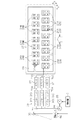
図1は、ラテラル方式のインクジェット式プリンターを備えた印刷システムの模式図である。図1に示すように、印刷システム100は、画像データを生成する画像生成装置110と、画像生成装置110から受信した画像データを基に印刷データを生成するホスト装置120と、ホスト装置120から受信した印刷データに基づく画像を印刷する印刷装置の一例としてのラテラル方式のインクジェット式プリンター(以下、単に「プリンター」ともいう。)11とを備えている。   FIG. 1 is a schematic diagram of a printing system including a lateral type ink jet printer. As illustrated in FIG. 1, the printing system 100 includes an image generation device 110 that generates image data, a host device 120 that generates print data based on the image data received from the image generation device 110, and a reception from the host device 120. A lateral ink jet printer (hereinafter also simply referred to as “printer”) 11 is provided as an example of a printing apparatus that prints an image based on the print data.

画像生成装置110は、例えばパーソナルコンピューターにより構成され、その本体111内のCPUが画像作成用ソフトウェアを実行することで構築される画像生成部112を備えている。ユーザーは、画像生成部112を起動させて入力装置113を操作することにより、モニター114上で画像を作成し、画像の印刷を指示する。すると、その画像に係る画像データは、所定の通信インターフェイスを介してホスト装置120へ送信される。   The image generation device 110 is configured by a personal computer, for example, and includes an image generation unit 112 that is constructed by a CPU in the main body 111 executing image generation software. The user activates the image generation unit 112 and operates the input device 113 to create an image on the monitor 114 and instruct printing of the image. Then, the image data relating to the image is transmitted to the host device 120 via a predetermined communication interface.

ホスト装置120は、例えばパーソナルコンピューターにより構成され、その本体121内のCPUがプリンタードライバー用ソフトウェアを実行することで構築されるプリンタードライバー122と、ユーザーによって操作される操作部124とを備えている。プリンタードライバー122は、画像生成装置110から受信した画像データを基に印刷データを生成し、プリンター11に設けられた情報処理システムの一例としての制御装置Cへ送信する。制御装置Cは、プリンタードライバー122から受信した印刷データに基づいてプリンター11を制御し、プリンター11に印刷データに基づく画像を印刷させる。なお、モニター123には、プリンター11に制御用設定値を入力設定するためのメニュー画面、プリンター11で発生したエラーを報知するエラー画面及び印刷対象の画像などが表示される。   The host device 120 is configured by a personal computer, for example, and includes a printer driver 122 constructed by a CPU in the main body 121 executing printer driver software, and an operation unit 124 operated by a user. The printer driver 122 generates print data based on the image data received from the image generation apparatus 110 and transmits the print data to the control apparatus C as an example of an information processing system provided in the printer 11. The control device C controls the printer 11 based on the print data received from the printer driver 122 and causes the printer 11 to print an image based on the print data. The monitor 123 displays a menu screen for inputting control setting values to the printer 11, an error screen for notifying an error that has occurred in the printer 11, an image to be printed, and the like.

次に、図1に示すプリンター11の構成について説明する。なお、以下における明細書中の説明において、「左右方向」、「上下方向」をいう場合は、図1等の図面に矢印で示した方向を基準として示すものとする。また、図1において手前側を前側、奥側を後側とする。   Next, the configuration of the printer 11 shown in FIG. 1 will be described. In the following description in the specification, the terms “left-right direction” and “up-down direction” refer to the direction indicated by the arrow in the drawing such as FIG. In FIG. 1, the front side is the front side, and the back side is the rear side.

図1に示すように、プリンター11は、直方体状の本体ケース12を備えている。本体ケース12内には、印刷媒体の一例としての長尺状のシート13を繰り出す繰出し部14と、そのシート13にインク(流体)の噴射により印刷を施す印刷室15と、その印刷によりインクが付着したシート13に乾燥処理を施す乾燥装置16と、乾燥処理が施されたシート13を巻き取る巻取り部17とが設けられている。   As shown in FIG. 1, the printer 11 includes a rectangular parallelepiped main body case 12. In the main body case 12, a feeding portion 14 that feeds out a long sheet 13 as an example of a printing medium, a printing chamber 15 that performs printing by ejecting ink (fluid) on the sheet 13, and ink by the printing are provided. A drying device 16 that performs a drying process on the attached sheet 13 and a winding unit 17 that winds the sheet 13 that has been subjected to the drying process are provided.

すなわち、本体ケース12内におけるやや上寄りの位置には、本体ケース12内を上下に区画する平板状の基台18が設けられており、この基台18よりも上側の領域が矩形板状の支持部材19を基台18上に支持してなる印刷室15となっている。そして、基台18よりも下側の領域において、シート13の搬送方向で上流側となる左側寄りの位置に、繰出し部14が配設されると共に、下流側となる右側寄りの位置に、乾燥装置16及び巻取り部17が配設されている。   That is, a flat base 18 that vertically divides the inside of the main body case 12 is provided at a position slightly above in the main body case 12, and a region above the base 18 has a rectangular plate shape. The printing chamber 15 is formed by supporting the support member 19 on the base 18. In the region below the base 18, the feeding unit 14 is disposed at a position on the left side on the upstream side in the conveyance direction of the sheet 13, and is dried at a position on the right side on the downstream side. A device 16 and a winding part 17 are arranged.

繰出し部14には、前後方向に延びる巻き軸20が回転自在に設けられ、その巻き軸20に対してシート13が予めロール状に巻かれた状態で一体回転可能に支持されている。すなわち、シート13は、巻き軸20が回転することにより、繰出し部14から繰り出される。また、繰出し部14から繰り出されたシート13は、巻き軸20の右側に位置する第1ローラー21に巻き掛けられて上方へ案内される。   A winding shaft 20 extending in the front-rear direction is rotatably provided in the feeding portion 14, and the sheet 13 is supported on the winding shaft 20 so as to be integrally rotatable in a state of being wound in a roll shape in advance. That is, the sheet 13 is fed out from the feeding unit 14 as the winding shaft 20 rotates. Further, the sheet 13 fed out from the feeding unit 14 is wound around the first roller 21 located on the right side of the winding shaft 20 and guided upward.

一方、支持部材19の左側であって下側の第1ローラー21と上下方向で対応する位置には、第2ローラー22が下側の第1ローラー21と平行な状態で設けられている。そして、第1ローラー21によって搬送方向が鉛直上方向に変換されたシート13は、第2ローラー22に左側下方から巻き掛けられることにより、その搬送方向が水平右方向に変換されて支持部材19の上面に摺接する。   On the other hand, a second roller 22 is provided in parallel with the lower first roller 21 at a position corresponding to the lower first roller 21 in the vertical direction on the left side of the support member 19. And the sheet | seat 13 by which the conveyance direction was converted into the vertically upward direction by the 1st roller 21 is wound around the 2nd roller 22 from the lower left side, The conveyance direction is converted into the horizontal right direction, and the support member 19 of FIG. Touch the upper surface.

また、支持部材19の右側には、左側の第2ローラー22と支持部材19を挟んで対向する第3ローラー23が第2ローラー22と平行な状態で設けられている。なお、第2ローラー22及び第3ローラー23は、各々の周面の頂部が支持部材19の上面と同一高さとなるように位置調整されている。   Further, on the right side of the support member 19, a third roller 23 facing the second roller 22 on the left side and the support member 19 is provided in parallel with the second roller 22. The positions of the second roller 22 and the third roller 23 are adjusted so that the tops of the respective peripheral surfaces are at the same height as the upper surface of the support member 19.

印刷室15内で左側の第2ローラー22により搬送方向が水平右方向に変換されたシート13は、支持部材19の上面に摺接しつつ下流側となる右側に搬送された後、第3ローラー23に右側上方から巻き掛けられることにより搬送方向が鉛直下方向に変換されて基台18よりも下側の乾燥装置16に向けて搬送される。そして、乾燥装置16内を通過することにより乾燥処理が施されたシート13は、更に鉛直下方向に搬送された後、第4ローラー24に巻き掛けられて搬送方向を水平右方向に変換され、第4ローラー24の右側に配設された巻取り部17の巻取り軸25が搬送モーター61(図3参照)の駆動力に基づいて回転することによりロール状に巻き取られる。   The sheet 13 whose conveyance direction is changed to the horizontal right direction by the left second roller 22 in the printing chamber 15 is conveyed to the right side which is the downstream side while being in sliding contact with the upper surface of the support member 19, and then the third roller 23. By being wound from above the right side, the conveying direction is changed to the vertically downward direction and conveyed toward the drying device 16 below the base 18. The sheet 13 that has been dried by passing through the drying device 16 is further transported vertically downward, and is then wound around the fourth roller 24 to change the transport direction to the horizontal right direction. The winding shaft 25 of the winding unit 17 disposed on the right side of the fourth roller 24 rotates based on the driving force of the transport motor 61 (see FIG. 3) to be wound into a roll.

印刷室15内における支持部材19の前後両側には、左右方向に延びるガイドレール26(図1では2点鎖線で示す。)が対をなすように設けられている。ガイドレール26の上面は支持部材19の上面よりも高くなっており、両ガイドレール26の上面には、矩形状のキャリッジ27が第1及び第2キャリッジモーター62,63(図3参照)の駆動に基づき両ガイドレール26に沿って主走査方向X(図1では左右方向)への往復移動が可能な状態で支持されている。そして、このキャリッジ27の下面側には支持板28を介して複数の記録ヘッド(印刷ヘッド)29が支持されている。なお、本実施形態では、第1キャリッジモーター62を「第1CRモーター62」というと共に、第2キャリッジモーター63を「第2CRモーター63」というものとする。   Guide rails 26 (indicated by a two-dot chain line in FIG. 1) extending in the left-right direction are provided on both front and rear sides of the support member 19 in the printing chamber 15 so as to form a pair. The upper surface of the guide rail 26 is higher than the upper surface of the support member 19, and a rectangular carriage 27 is driven on the upper surfaces of both guide rails 26 to drive the first and second carriage motors 62 and 63 (see FIG. 3). Is supported in a state in which reciprocation in the main scanning direction X (left-right direction in FIG. 1) is possible along both guide rails 26. A plurality of recording heads (printing heads) 29 are supported on the lower surface side of the carriage 27 via support plates 28. In the present embodiment, the first carriage motor 62 is referred to as a “first CR motor 62”, and the second carriage motor 63 is referred to as a “second CR motor 63”.

支持部材19の左端から右端までの一定範囲が印刷領域とされており、この印刷領域単位でシート13は間欠的に搬送される。そして、支持部材19上に停止したシート13に対してキャリッジ27の往復移動に伴い記録ヘッド29からインクが噴射されることでシート13に印刷が施される。   A fixed range from the left end to the right end of the support member 19 is a printing area, and the sheet 13 is intermittently conveyed in units of the printing area. Then, printing is performed on the sheet 13 by ejecting ink from the recording head 29 as the carriage 27 reciprocates on the sheet 13 stopped on the support member 19.

なお、印刷時には、支持部材19の下側に設けられた吸引装置30が駆動され、支持部材19の上面に開口する多数の吸引孔に及ぶ負圧による吸引力により、シート13が支持部材19の上面に吸着される。そして、シート13への1回分の印刷が終わると、吸引装置30の負圧が解除され、シート13の搬送が行われる。   At the time of printing, the suction device 30 provided on the lower side of the support member 19 is driven, and the sheet 13 is attached to the support member 19 by suction force due to negative pressure that reaches a large number of suction holes opened on the upper surface of the support member 19. Adsorbed on the top surface. Then, when one printing on the sheet 13 is finished, the negative pressure of the suction device 30 is released, and the sheet 13 is conveyed.

また、印刷室15内において、第3ローラー23よりも右側となる非印刷領域には、非印刷時に記録ヘッド29のメンテナンスを行うためのメンテナンス装置32が設けられている。メンテナンス装置32は、記録ヘッド29毎にキャップ33と昇降装置34とを備えている。各キャップ33は、昇降装置34の駆動により、記録ヘッド29のノズル形成面35(図2参照)に当接するキャッピング位置と、ノズル形成面35から離間する退避位置との間を移動する。   In the printing chamber 15, a maintenance device 32 for performing maintenance of the recording head 29 at the time of non-printing is provided in a non-printing region on the right side of the third roller 23. The maintenance device 32 includes a cap 33 and a lifting device 34 for each recording head 29. Each cap 33 moves between a capping position that contacts the nozzle forming surface 35 (see FIG. 2) of the recording head 29 and a retracted position that is separated from the nozzle forming surface 35 by driving the lifting device 34.

また、本体ケース12内には、異なる色のインクをそれぞれ収容した複数(例えば8個)のインクカートリッジ(収容容器)IC1,IC2,IC3,IC4,IC5,IC6,IC7,IC8が着脱可能に装着されている。これら各インクカートリッジIC1〜IC8は、インク供給路70A(図2参照)などを通じて記録ヘッド29に接続され、各記録ヘッド29は、各インクカートリッジIC1〜IC8から供給されたインクを噴射する。すなわち、本実施形態のプリンター11では、8色のインクを用いたカラー印刷が可能となっている。なお、図1及び図2に示すように、本体ケース12においてインクカートリッジIC1〜IC8の配置位置と対応する箇所には、開閉式のカバー38が設けられている。そして、インクカートリッジIC1〜IC8の交換作業は、カバー38を開けた状態で行われる。   In the main body case 12, a plurality of (for example, eight) ink cartridges (containers) IC1, IC2, IC3, IC4, IC5, IC6, IC7, and IC8, each containing ink of different colors, are detachably mounted. Has been. Each of these ink cartridges IC1 to IC8 is connected to the recording head 29 through an ink supply path 70A (see FIG. 2) or the like, and each recording head 29 ejects ink supplied from each of the ink cartridges IC1 to IC8. That is, the printer 11 according to the present embodiment can perform color printing using eight colors of ink. As shown in FIGS. 1 and 2, an openable / closable cover 38 is provided at a position corresponding to the arrangement position of the ink cartridges IC <b> 1 to IC <b> 8 in the main body case 12. The ink cartridges IC1 to IC8 are exchanged with the cover 38 opened.

8個のインクカートリッジIC1〜IC8は、例えば黒(K)、シアン(C)、マゼンタ(M)、イエロー(Y)等の各インクを収容する。なお、保湿液を収容する保湿液カートリッジが装填される構成も採用できる。もちろん、インクの種類(色数)は適宜設定でき、黒インクだけでモノクロ印刷する構成や、インクを2色としたり、8色以外で3色以上の任意の色数としたりした構成も採用できる。   The eight ink cartridges IC1 to IC8 contain inks such as black (K), cyan (C), magenta (M), and yellow (Y). A configuration in which a moisturizing liquid cartridge that stores the moisturizing liquid is loaded can also be employed. Of course, the type (number of colors) of the ink can be set as appropriate, and a configuration in which monochrome printing is performed using only black ink, or a configuration in which the ink is set to two colors, or an arbitrary number of colors other than eight colors such as three or more can be employed. .

各インクカートリッジIC1〜IC8は、図示しないカートリッジホルダーを介して制御装置Cと電気的にそれぞれ接続されている。そして、各インクカートリッジIC1〜IC8に実装された不揮発性の記憶素子47(図3参照)には、対応する色のインク残量情報が書き込まれる。   Each of the ink cartridges IC1 to IC8 is electrically connected to the control device C via a cartridge holder (not shown). Then, ink remaining amount information of the corresponding color is written in the non-volatile storage element 47 (see FIG. 3) mounted in each of the ink cartridges IC1 to IC8.

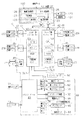
図2は、キャリッジの底面に設けられた複数の記録ヘッドと、各記録ヘッドへインクを供給するインク供給装置とを示す模式図である。図2に示すように、キャリッジ27の下面側に支持された支持板28には、複数個(本実施形態では15個)の記録ヘッド29がシート13の搬送方向(図2において白抜き矢印で示す方向)と直交する幅方向(前後方向)に亘って千鳥状の配置パターンで支持されている。そして、各記録ヘッド29の下面となるノズル形成面35には、多数のノズル36が前後方向(副走査方向Y)に沿って1列に配置されてなるノズル列37が主走査方向Xに所定間隔をおいて複数列(本実施形態では8列)形成されている。   FIG. 2 is a schematic diagram illustrating a plurality of recording heads provided on the bottom surface of the carriage and an ink supply device that supplies ink to each recording head. As shown in FIG. 2, on the support plate 28 supported on the lower surface side of the carriage 27, a plurality (15 in this embodiment) of recording heads 29 are conveyed in the sheet 13 conveyance direction (indicated by white arrows in FIG. 2). It is supported in a staggered arrangement pattern in the width direction (front-rear direction) orthogonal to the direction shown. A nozzle array 37 in which a large number of nozzles 36 are arranged in a line along the front-rear direction (sub-scanning direction Y) is predetermined in the main scanning direction X on the nozzle forming surface 35 that is the lower surface of each recording head 29. A plurality of rows (eight rows in this embodiment) are formed at intervals.

本実施形態のプリンター11には、各インクカートリッジIC1〜IC8に個別対応する複数(本実施形態では8個)のサブタンク(貯留部)67と、図示しないカートリッジホルダーに装着されたインクカートリッジIC1〜IC8からインクをサブタンク67に供給するためのインク供給装置39とが設けられている。このインク供給装置39は、ポンプモーター65、加圧ポンプ66及び図示しないカートリッジホルダーを備えている。   In the printer 11 of the present embodiment, a plurality (eight in this embodiment) of sub-tanks (reservoirs) 67 individually corresponding to the ink cartridges IC1 to IC8, and ink cartridges IC1 to IC8 mounted on a cartridge holder (not shown). And an ink supply device 39 for supplying ink to the sub tank 67. The ink supply device 39 includes a pump motor 65, a pressure pump 66, and a cartridge holder (not shown).

カートリッジホルダーに装着されたインクカートリッジIC1〜IC8は、インク供給路70A(例えばチューブ)を通じてサブタンク67に接続されている。また、サブタンク67は、インクカートリッジIC1〜IC8から供給されたインクを一時的に貯留するタンクであって、インク供給路70B(例えばチューブ)を通じて各記録ヘッド29に接続されている。但し、図2では、複数(例えば8個)のサブタンク67は1つの記録ヘッド29との接続関係のみ示している。実際には、8個のサブタンク67からは記録ヘッド29と同数本のインク供給路70B(例えばチューブ)が延びており、各インク供給路70Bそれぞれ対応する記録ヘッド29に接続されている。インクカートリッジIC1〜IC8からの各色のインクは、サブタンク67及びインク供給路70Bを通じて各記録ヘッド29に供給される。   The ink cartridges IC1 to IC8 mounted on the cartridge holder are connected to the sub tank 67 through the ink supply path 70A (for example, a tube). The sub tank 67 is a tank that temporarily stores ink supplied from the ink cartridges IC1 to IC8, and is connected to each recording head 29 through an ink supply path 70B (for example, a tube). However, in FIG. 2, a plurality of (for example, eight) sub tanks 67 show only the connection relationship with one recording head 29. Actually, the same number of ink supply paths 70B (for example, tubes) as the recording heads 29 extend from the eight sub-tanks 67 and are connected to the corresponding recording heads 29. The inks of the respective colors from the ink cartridges IC1 to IC8 are supplied to the recording heads 29 through the sub tanks 67 and the ink supply paths 70B.

また、カートリッジホルダーに装着されたインクカートリッジIC1〜IC8は、加圧ポンプ66の吐出口と空気供給路71を通じて接続される。制御装置Cがポンプモーター65を駆動して加圧ポンプ66がポンプ駆動されることにより、加圧ポンプ66から吐出された加圧空気が空気供給路71を通じてインクカートリッジIC1〜IC8内に供給される。したがって、本実施形態では、インク供給装置39、サブタンク67及び記録ヘッド29により、印刷媒体に印刷を行う出力手段が構成される。   The ink cartridges IC <b> 1 to IC <b> 8 mounted on the cartridge holder are connected to the discharge port of the pressure pump 66 through the air supply path 71. When the control device C drives the pump motor 65 and the pressure pump 66 is pump-driven, the pressurized air discharged from the pressure pump 66 is supplied into the ink cartridges IC1 to IC8 through the air supply path 71. . Therefore, in the present embodiment, the ink supply device 39, the sub tank 67, and the recording head 29 constitute an output unit that performs printing on a print medium.

また、本体ケース12において図2に実線で示す閉状態にあるカバー38の回動端と対応する位置には、カバー38を閉状態にロックするための電磁ロック68が設けられている。例えば本体ケース12におけるカバー38の近傍位置には、ユーザーがカバー38のロック/ロック解除の操作をするための操作スイッチ72(図3参照)が設けられている。制御装置Cは、操作スイッチ72からカバー38をロックさせる操作がなされた際のロック信号を入力すると、電磁ロック68を励磁駆動させることによりカバー38を閉状態にロックさせる。また、制御装置Cは、操作スイッチ72からカバー38のロックを解除させる操作がなされた際のロック解除信号を入力すると、電磁ロック68を消磁させることによりカバー38をロック解除させる。カートリッジ交換を行う際は、図2に示すように、カバー38を二点鎖線で示す開状態(但し最大開度は図2の状態より大きい)で、インクカートリッジIC1〜IC8のうち少なくとも1個の交換を行って再びカバー38を図2に実線で示す閉状態とした後、操作スイッチ72を操作することでカバー38を閉状態にロックさせる。なお、カバーロックを指示する方式は、操作スイッチ72による操作方式に限定されず、カバー38が閉状態にあることを検知するセンサーから制御装置Cが閉検知信号を入力したときに電磁ロック68を励磁駆動させる構成も採用できる。   Further, an electromagnetic lock 68 for locking the cover 38 in the closed state is provided at a position corresponding to the rotation end of the cover 38 in the closed state shown by a solid line in FIG. For example, an operation switch 72 (see FIG. 3) for the user to lock / unlock the cover 38 is provided at a position near the cover 38 in the main body case 12. When the control device C receives a lock signal when the operation of locking the cover 38 is performed from the operation switch 72, the control device C locks the cover 38 in the closed state by exciting the electromagnetic lock 68. In addition, when the control device C inputs an unlock signal when an operation for unlocking the cover 38 is performed from the operation switch 72, the control device C unlocks the cover 38 by demagnetizing the electromagnetic lock 68. When the cartridge is replaced, as shown in FIG. 2, the cover 38 is in an open state indicated by a two-dot chain line (however, the maximum opening is larger than the state shown in FIG. 2), and at least one of the ink cartridges IC1 to IC8 is used. After the replacement, the cover 38 is again closed as shown by the solid line in FIG. 2, and then the cover 38 is locked in the closed state by operating the operation switch 72. The method of instructing the cover lock is not limited to the operation method by the operation switch 72, and the electromagnetic lock 68 is set when the control device C inputs a close detection signal from a sensor that detects that the cover 38 is in the closed state. A configuration in which excitation drive is performed can also be adopted.

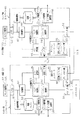
図3は、印刷システム100の電気構成を示すブロック図である。図3に示すホスト装置(他の情報処理装置)120内のプリンタードライバー122は、モニター123に表示させるべきメニュー画面などの各種画面の表示制御を行うと共に、各画面の表示状態において操作部124から入力した操作信号に応じた所定処理を行うホスト制御部125を備えている。このホスト制御部125は、プリンタードライバー122を統括的に制御する。また、プリンタードライバー122は、上位の画像生成装置110から受信した画像データに対して印刷データの生成に必要な画像処理を施す、解像度変換部126、色変換部127及びハーフトーン処理部128を備えている。解像度変換部126は、画像データを表示解像度から印刷解像度へ変換する解像度変換処理を行う。色変換部127は、表示用の表色系(例えばRGB表色系やYCbCr表色系)から印刷用の表色系(例えばCMYK表色系)に色変換する色変換処理を行う。さらにハーフトーン処理部128は、表示用の高階調(例えば256階調)の画素データを印刷用の低階調(例えば2階調又は4階調)の画素データに階調変換するハーフトーン処理などを行う。そして、プリンタードライバー122は、これらの画像処理によって生成された印刷画像データに、印刷制御コード(例えばESC/P)で記述されたコマンドを付して駆動データの一例としての印刷ジョブデータ(以下、単に「印刷データ」ともいう。)を生成する。   FIG. 3 is a block diagram illustrating an electrical configuration of the printing system 100. The printer driver 122 in the host apparatus (another information processing apparatus) 120 illustrated in FIG. 3 performs display control of various screens such as a menu screen to be displayed on the monitor 123, and from the operation unit 124 in the display state of each screen. A host control unit 125 that performs a predetermined process according to the input operation signal is provided. The host control unit 125 controls the printer driver 122 in an integrated manner. In addition, the printer driver 122 includes a resolution conversion unit 126, a color conversion unit 127, and a halftone processing unit 128 that perform image processing necessary for generating print data on the image data received from the higher-level image generation apparatus 110. ing. The resolution conversion unit 126 performs resolution conversion processing for converting image data from display resolution to print resolution. The color conversion unit 127 performs color conversion processing for color conversion from a display color system (for example, RGB color system or YCbCr color system) to a print color system (for example, CMYK color system). Furthermore, the halftone processing unit 128 converts halftone processing for converting high gradation (for example, 256 gradation) pixel data for display into low gradation (for example, two or four gradations) pixel data for printing. And so on. Then, the printer driver 122 attaches a command described by a print control code (for example, ESC / P) to the print image data generated by the image processing, and print job data (hereinafter referred to as drive data) (hereinafter referred to as drive data). Simply referred to as "print data").

ホスト装置120は、データの転送制御を行う転送制御部129を備えている。この転送制御部129は、プリンタードライバー122で生成された印刷データを所定容量のパケットデータずつ制御装置Cへ順次シリアル転送する。   The host device 120 includes a transfer control unit 129 that performs data transfer control. The transfer control unit 129 serially transfers the print data generated by the printer driver 122 to the control device C sequentially for each predetermined amount of packet data.

プリンター11側の制御装置Cは、ホスト装置120から印刷データを受信して記録系の制御をはじめとする各種制御を行う一対のコントローラー(情報処理装置)41,42を備えている。一対のコントローラー41,42は、複数個(本例では15個)の記録ヘッド29を所定個数(本例では7個と8個)の2つに分けて分担して制御する。すなわち、マスター側コントローラー41が7個の記録ヘッド29Bの制御を受け持ち、スレーブ側コントローラー42が8個の記録ヘッド29Aの制御を受け持つ。   The control device C on the printer 11 side includes a pair of controllers (information processing devices) 41 and 42 that receive print data from the host device 120 and perform various controls including control of the recording system. The pair of controllers 41 and 42 divide and control a plurality (15 in this example) of recording heads 29 by dividing them into a predetermined number (7 and 8 in this example). That is, the master-side controller 41 is responsible for controlling the seven recording heads 29B, and the slave-side controller 42 is responsible for controlling the eight recording heads 29A.

なお、図2に示すキャリッジ27に設けられた15個の記録ヘッド29は、副走査方向Yに沿って2列で配列された記録ヘッド29A,29Bが副走査方向Yに半ピッチ分ずつずれた千鳥配置をとっている。そして、図3に示す各コントローラー41,42は、2列のうち1列分ずつの記録ヘッド29A,29Bをそれぞれ分担する。   Note that the fifteen recording heads 29 provided on the carriage 27 shown in FIG. 2 have recording heads 29A and 29B arranged in two rows along the sub-scanning direction Y shifted by a half pitch in the sub-scanning direction Y. Staggered arrangement. Each of the controllers 41 and 42 shown in FIG. 3 shares the recording heads 29A and 29B for each of the two rows.

さらに、制御装置Cは、マスター側コントローラー41の出力側(制御下流側)に通信線SL1を通じて接続されたメカコントローラー43を備えている。メカコントローラー43は、主に搬送系及びキャリッジ駆動系を含むメカニカル機構部44の制御を司る。マスター側コントローラー41は、自身が受け持つ7個の記録ヘッド29Bの印刷準備ができ(つまりインク滴噴射制御に使用する印刷画像データが揃っており)、且つスレーブ側コントローラー42が受け持つ8個の記録ヘッド29Aも印刷準備ができた段階でキャリッジ起動コマンドをメカコントローラー43へ送信する。これにより、コントローラー41,42のうち一方の印刷準備完了前にキャリッジ27が起動されてしまうことに起因し、記録ヘッド29が噴射位置に到達したにも拘わらずインク滴が噴射されない噴射ミスが防止される。   Furthermore, the control device C includes a mechanical controller 43 connected to the output side (control downstream side) of the master controller 41 through the communication line SL1. The mechanical controller 43 mainly controls the mechanical mechanism unit 44 including a transport system and a carriage drive system. The master-side controller 41 is ready for printing of the seven recording heads 29B that it is responsible for (that is, print image data used for ink droplet ejection control is ready), and the eight recording heads that the slave-side controller 42 is responsible for. 29A also sends a carriage activation command to the mechanical controller 43 when printing is ready. This prevents an ejection error in which ink droplets are not ejected even though the recording head 29 has reached the ejection position, due to the carriage 27 being activated before one of the controllers 41 and 42 is ready for printing. Is done.

また、マスター側コントローラー41は、自身が受け持つ7個の記録ヘッド29Bの印刷を完了し、且つスレーブ側コントローラー42が受け持つ8個の記録ヘッド29Aも印刷を完了した段階で、シート13の搬送を指令する搬送コマンドをメカコントローラー43へ送信する。これにより、コントローラー41,42のうち一方が印刷完了前の段階でシート13が搬送開始(又は支持部材19上のシートの吸着解除)されてしまうことに起因し、記録ヘッド29から噴射されたインク滴のシート13に対する着弾位置のずれ(印刷位置ずれ)が防止される。このようにマスター側コントローラー41は、スレーブ側コントローラー42と進捗の同期をとってコマンドを送信する機能を備えている。そして、両コントローラー41,42は、制御上の同期をとるために、他方のコントローラーへコマンドを出力するスレーブ側と、スレーブ側から受け付けたコマンドと自身のコマンドとが揃い且つコマンド内容が一致することを確認した時点でメカコントローラー43へコマンドを出力するマスター側とに分かれる。本実施形態では、制御上の同期をとるための仕組みの部分でマスター側とスレーブ側とで異なる部分があっても、マスター側コントローラー41とスレーブ側コントローラー42とを同じプログラムの構成で実現している。この特徴部分については後述する。   In addition, the master-side controller 41 completes printing of the seven recording heads 29B that it is responsible for, and instructs the conveyance of the sheet 13 when the eight recording heads 29A that are handled by the slave-side controller 42 are also completed. The conveyance command to be transmitted is transmitted to the mechanical controller 43. As a result, the ink ejected from the recording head 29 due to one of the controllers 41 and 42 starting to convey the sheet 13 (or releasing the suction of the sheet on the support member 19) before the printing is completed. Deviation of the landing position of the droplet on the sheet 13 (print position deviation) is prevented. Thus, the master-side controller 41 has a function of transmitting a command in synchronization with the progress of the slave-side controller 42. Then, in order to synchronize the control, both the controllers 41 and 42 are configured so that the slave side that outputs a command to the other controller, the command received from the slave side, and its own command are aligned and the command contents are the same. Is confirmed, the master side that outputs a command to the mechanical controller 43 is divided. In the present embodiment, the master controller 41 and the slave controller 42 are realized by the same program configuration even if there is a difference between the master side and the slave side in the mechanism for synchronization in control. Yes. This characteristic part will be described later.

図3に示すホスト装置120内のプリンタードライバー122は、2つのコントローラー41,42のそれぞれが受け持つ記録ヘッド29の配置位置に応じて印刷画像データを2つに分割し、分割した各印刷画像データに同一のコマンドを付して2つの印刷データを生成する。   The printer driver 122 in the host device 120 shown in FIG. 3 divides the print image data into two according to the arrangement position of the recording head 29 which each of the two controllers 41 and 42 is responsible for. Two print data are generated with the same command.

図3に示すように、ホスト装置120は、2つのシリアル通信ポートU1,U2を備えている。また、2つのコントローラー41,42もそれぞれシリアル通信ポートU3,U4を備えている。そして、転送制御部129は、シリアル通信ポートU1,U3間の通信を介してマスター側コントローラー41へ対応する印刷データをシリアル転送すると共に、シリアル通信ポートU2,U4間の通信を介してスレーブ側コントローラー42へ対応する印刷データをシリアル転送する。本実施形態では、シリアル通信ポートU1〜U4として、例えばUSB(Universal Serial Bus)ポートが用いられる。ホスト装置120は、2つのシリアル通信ポートU1,U2を構成する2つのUSBホストによって2系統でシリアル転送を行って、各コントローラー41,42へ比較的高速に印刷データを転送する。   As shown in FIG. 3, the host device 120 includes two serial communication ports U1 and U2. The two controllers 41 and 42 also have serial communication ports U3 and U4, respectively. Then, the transfer control unit 129 serially transfers the print data corresponding to the master controller 41 via the communication between the serial communication ports U1 and U3, and at the same time the slave controller via the communication between the serial communication ports U2 and U4. The print data corresponding to 42 is serially transferred. In the present embodiment, for example, USB (Universal Serial Bus) ports are used as the serial communication ports U1 to U4. The host device 120 performs serial transfer in two systems by two USB hosts constituting the two serial communication ports U1 and U2, and transfers print data to the controllers 41 and 42 at a relatively high speed.

但し、2系統であるものの比較的遅いシリアル転送であるため、本実施形態のラテラル式のプリンター11では、1回分(1頁分)の印刷データを全て受信し終わってから印刷が開始される。これは、例えば1パス分の印刷データ受信完了段階で印刷を開始すると、途中で次パスの印刷データの受信完了を待つ待機時間ができ、このときノズル36内におけるインクの増粘によるノズル36の目詰まりを回避すべく、キャリッジ27を非印刷領域内のホーム位置(待機位置)へ一時退避させて、記録ヘッド29をキャップ33でキャッピングする必要が生じるからである。このように1回の印刷途中でキャリッジ27をホーム位置に退避させていると、却って印刷所要時間が長くなってしまうので、1回分(1頁分)の印刷データを全て受信してから、印刷を開始するようにしている。   However, because of the relatively slow serial transfer of the two systems, the lateral printer 11 of this embodiment starts printing after receiving all the print data for one time (for one page). For example, when printing is started at the completion stage of reception of print data for one pass, a waiting time can be waited for the completion of reception of print data for the next pass in the middle. This is because it is necessary to temporarily retract the carriage 27 to the home position (standby position) in the non-printing area and capping the recording head 29 with the cap 33 in order to avoid clogging. If the carriage 27 is retracted to the home position in the middle of one printing in this way, the time required for printing becomes longer on the contrary. Therefore, after all the printing data for one time (for one page) is received, printing is performed. Like to start.

2つのコントローラー41,42には、複数個(N個(本例では4個))ずつのヘッド制御ユニット(以下、「HCU」ともいう。)45が接続され、各HCU45にはそれ一個につき記録ヘッド29が複数個(M個(本例では2個))ずつ接続されている。   A plurality of (N (4 in this example)) head control units (hereinafter also referred to as “HCUs”) 45 are connected to the two controllers 41, 42, and each HCU 45 is recorded for each one. A plurality of heads 29 (M (two in this example)) are connected.

また、2つのコントローラー41,42に接続された各通信回路46には、8個のインクカートリッジIC1〜IC8に実装された8個の記憶素子47のうち半分の4個ずつがそれぞれ接続されている。マスター側コントローラー41は、4個のインクカートリッジIC1〜IC4に実装された記憶素子47と通信可能であり、スレーブ側コントローラー42は、4個のインクカートリッジIC5〜IC8に実装された記憶素子47と通信可能である。記憶素子47には、対応するインクカートリッジICのインク残量情報、インク色、使用期限、メンテナンス情報、品番などの各種のインク関連情報が記憶される。   In addition, each communication circuit 46 connected to the two controllers 41 and 42 is connected to each of four half of the eight storage elements 47 mounted on the eight ink cartridges IC1 to IC8. . The master controller 41 can communicate with the storage elements 47 mounted on the four ink cartridges IC1 to IC4, and the slave controller 42 communicates with the storage elements 47 mounted on the four ink cartridges IC5 to IC8. Is possible. The storage element 47 stores various ink-related information such as ink remaining amount information, ink color, expiration date, maintenance information, and product number of the corresponding ink cartridge IC.

マスター側コントローラー41は、4個のインクカートリッジIC1〜IC4のインク残量を管理し、一方のスレーブ側コントローラー42は、残り4個のインクカートリッジIC5〜IC8のインク残量を管理する。マスター側コントローラー41は、通信回路46を介してインクカートリッジIC1〜IC4の各記憶素子47と通信してそのメモリーに記憶されたインク情報及びインク残量情報の読み出し及びインク残量情報の書込みが可能となっている。同様に、スレーブ側コントローラー42は、通信回路46を介して各インクカートリッジIC5〜IC8に実装された記憶素子47と通信してそのメモリーに記憶されたインク情報及びインク残量情報の読み出し及びインク残量情報の書込みが可能となっている。   The master controller 41 manages the remaining ink levels of the four ink cartridges IC1 to IC4, and the slave controller 42 manages the remaining ink levels of the remaining four ink cartridges IC5 to IC8. The master-side controller 41 can communicate with the storage elements 47 of the ink cartridges IC1 to IC4 via the communication circuit 46 to read out the ink information and the remaining ink information stored in the memory and write the remaining ink information. It has become. Similarly, the slave-side controller 42 communicates with the storage elements 47 mounted on the ink cartridges IC5 to IC8 via the communication circuit 46, reads out the ink information and the ink remaining amount information stored in the memory, and the ink remaining amount. Quantity information can be written.

各コントローラー41,42は、プリンター11の起動時に記憶素子47のメモリーからインク残量を読み出し、管理対象のインクカートリッジで消費されたインク消費量を所定の時期に算出し、各インクカートリッジの現在のインク残量を逐次算出する。そして、各コントローラー41,42は、例えばプリンター11の電源遮断時にその管理している現在のインク残量情報を記憶素子47に書き込む処理を行う。例えばホスト装置120は、プリンター11の各コントローラー41,42と通信してインク残量情報を取得し、そのモニター123(図1参照)に各インクカートリッジIC1〜IC8のインク残量を表示する。   Each controller 41, 42 reads the remaining amount of ink from the memory of the storage element 47 when the printer 11 is activated, calculates the amount of ink consumed by the management target ink cartridge at a predetermined time, and determines the current amount of each ink cartridge. The remaining amount of ink is calculated sequentially. Each of the controllers 41 and 42 performs a process of writing the current ink remaining amount information managed in the storage element 47 when the printer 11 is turned off, for example. For example, the host device 120 communicates with the controllers 41 and 42 of the printer 11 to acquire ink remaining amount information, and displays the ink remaining amounts of the ink cartridges IC1 to IC8 on the monitor 123 (see FIG. 1).

2つのコントローラー41,42は、プリンター11に複数個設けられた記録ヘッド29及びインクカートリッジIC1〜IC8を分担して制御又は管理することにより、負担の軽減を図っている。   The two controllers 41 and 42 share the control head 29 and the ink cartridges IC <b> 1 to IC <b> 8 provided in the printer 11, thereby reducing the burden.

図3に示すように、マスター側コントローラー41には、リニアエンコーダー50が接続されている。このリニアエンコーダー50はキャリッジ27の移動経路に沿って設けられ、マスター側コントローラー41には、このリニアエンコーダー50からキャリッジ27の移動距離に比例する数のパルスをもつ検出信号(エンコーダーパルス信号)が入力される。マスター側コントローラー41に入力されたエンコーダーパルス信号は、両コントローラー41,42間に接続された信号線SL2を通じてスレーブ側コントローラー42へ伝達される。さらに、マスター側コントローラー41とスレーブ側コントローラー42は、通信線SL3を通じて互いに接続されている。   As shown in FIG. 3, a linear encoder 50 is connected to the master controller 41. The linear encoder 50 is provided along the movement path of the carriage 27, and a detection signal (encoder pulse signal) having a number of pulses proportional to the movement distance of the carriage 27 from the linear encoder 50 is input to the master-side controller 41. Is done. The encoder pulse signal input to the master controller 41 is transmitted to the slave controller 42 through the signal line SL2 connected between the controllers 41 and 42. Further, the master controller 41 and the slave controller 42 are connected to each other through the communication line SL3.

各コントローラー41,42は、CPU53(中央処理装置)、ASIC54(Application Specific IC(特定用途向け集積回路))、RAM55、及び不揮発性メモリー56をそれぞれ備えている。CPU53は、不揮発性メモリー56に記憶されたプログラムを実行することにより、印刷制御に必要な各種タスク(各種処理)を実行する。また、ASIC54は、印刷データの処理など記録系のデータ処理などを行う。ASIC54は、印刷画像データに基づき記録ヘッド29のインク滴噴射回数に相当するドット数を色別に計数し、記録ヘッド29毎の各色のドット数を合計して色別のインク消費量も算出する。このとき、マスター側のASIC54は、7個の記録ヘッド29Bのインク消費量を色別に算出し、一方のスレーブ側のASIC54は、8個の記録ヘッド29Aのインク消費量を色別に算出する。   Each of the controllers 41 and 42 includes a CPU 53 (central processing unit), an ASIC 54 (Application Specific IC), a RAM 55, and a nonvolatile memory 56, respectively. The CPU 53 executes various tasks (various processes) necessary for print control by executing a program stored in the nonvolatile memory 56. The ASIC 54 performs recording data processing such as print data processing. The ASIC 54 counts the number of dots corresponding to the number of ink droplet ejections of the recording head 29 based on the print image data, and calculates the ink consumption for each color by summing the number of dots of each color for each recording head 29. At this time, the ASIC 54 on the master side calculates the ink consumption of the seven recording heads 29B by color, and the ASIC 54 on the slave side calculates the ink consumption of the eight recording heads 29A by color.

そして、マスター側コントローラー41は、7個の記録ヘッド29Bが消費した8色分のインク消費量のうち、スレーブ側に接続された記憶素子47に保存すべき4色分のインク消費量をスレーブ側コントローラー42へ送る。一方、スレーブ側コントローラー42は、8個の記録ヘッド29Aが消費した8色分のインク消費量のうち、マスター側に接続された記憶素子47に保存すべき4色分のインク消費量をマスター側コントローラー41へ送る。そして、各コントローラー41,42は、自身のASIC54が算出した未送信の4色分のインク消費量と、相手側のコントローラーから受信した同色の4色分のインク消費量を色別に加算して、自身が受け持つ4個のインクカートリッジICのインク消費量をそれぞれ求める。そして、記憶素子47に記憶されたそれまでのインク残量から今回求めたインク消費量を減算し、その時々のインク残量を色毎に取得する。   Then, the master-side controller 41 sets the ink consumption for four colors to be stored in the storage element 47 connected to the slave side out of the ink consumption for eight colors consumed by the seven recording heads 29B. Send to controller 42. On the other hand, the slave controller 42 determines the ink consumption for four colors to be stored in the storage element 47 connected to the master side out of the ink consumption for eight colors consumed by the eight recording heads 29A. Send to controller 41. Then, each controller 41, 42 adds the ink consumption for four untransmitted colors calculated by its ASIC 54 and the ink consumption for the four colors of the same color received from the controller on the other side for each color, The respective ink consumptions of the four ink cartridge ICs that it handles are obtained. Then, the ink consumption determined this time is subtracted from the ink remaining amount stored so far stored in the storage element 47, and the ink remaining amount at that time is acquired for each color.

例えばホスト装置120のプリンタードライバー122からインク残量情報の要求を受け付けると、各コントローラー41,42は、互いに自身が管理する4色分のインク残量を相手側に送信する。そして、各コントローラー41,42は、相手側から受信した4色分のインク残量と、自身管理の4色分のインク残量との合計8色分のインク残量情報をホスト装置120のプリンタードライバー122へ送信する。プリンタードライバー122は、各コントローラー41,42のそれぞれから8色分のインク残量情報を受信し、そのうち一方(例えばマスター側)から受信した8色分のインク残量情報に基づいて、モニター123に8色分のインク残量を示すインジケーターを含む印刷条件設定画面を表示する。   For example, when a request for remaining ink information is received from the printer driver 122 of the host device 120, the controllers 41 and 42 transmit the remaining ink amounts for four colors managed by themselves to the other party. Each of the controllers 41 and 42 outputs the remaining ink information for the total of eight colors, including the remaining ink amount for the four colors received from the other party and the remaining ink amount for the four colors managed by the controller. Transmit to the driver 122. The printer driver 122 receives the remaining amount of ink information for eight colors from each of the controllers 41 and 42, and sends it to the monitor 123 based on the remaining amount of ink information for eight colors received from one of them (for example, the master side). A print condition setting screen including an indicator showing the remaining amount of ink for eight colors is displayed.

一方、メカコントローラー43には、モーター駆動回路60を介してメカニカル機構部44を構成する搬送モーター61、第1CRモーター62及び第2CRモーター63がそれぞれ接続されている。また、メカコントローラー43には、メンテナンス装置32及び電磁ロック68がそれぞれ接続されている。さらに、メカコントローラー43には、モーター駆動回路76を介してインク供給装置39を構成するポンプモーター65が接続されており、ポンプモーター65が駆動されることにより加圧ポンプ66が駆動される。   On the other hand, a transport motor 61, a first CR motor 62, and a second CR motor 63 constituting the mechanical mechanism unit 44 are connected to the mechanical controller 43 via a motor drive circuit 60, respectively. In addition, the maintenance device 32 and the electromagnetic lock 68 are connected to the mechanical controller 43, respectively. Further, a pump motor 65 constituting the ink supply device 39 is connected to the mechanical controller 43 via a motor drive circuit 76, and the pressure pump 66 is driven by driving the pump motor 65.

また、メカコントローラー43には、入力系として、前述の操作スイッチ72及びエンコーダー73がそれぞれ接続されている。メカコントローラー43は、操作スイッチ72からロック操作信号を入力すると電磁ロック68を励磁し、操作スイッチ72から解除操作信号を入力すると電磁ロック68を消磁する。なお、メカコントローラー43は、電磁ロック68を励磁させてカバー38をロックすると、カバー38が閉じていることを示す正常情報をマスター側コントローラー41に出力する。   Further, the operation switch 72 and the encoder 73 are connected to the mechanical controller 43 as an input system. The mechanical controller 43 energizes the electromagnetic lock 68 when a lock operation signal is input from the operation switch 72, and demagnetizes the electromagnetic lock 68 when a release operation signal is input from the operation switch 72. When the mechanical controller 43 excites the electromagnetic lock 68 and locks the cover 38, the mechanical controller 43 outputs normal information indicating that the cover 38 is closed to the master-side controller 41.

こうしたメカコントローラー43は、マスター側コントローラー41から通信線SL1を通じて受信した各種コマンドに従って、各モーター61〜63,65、メンテナンス装置32及び電磁ロック68を駆動制御する。   The mechanical controller 43 drives and controls the motors 61 to 63, 65, the maintenance device 32, and the electromagnetic lock 68 in accordance with various commands received from the master controller 41 through the communication line SL1.

制御装置Cは、印刷時に、搬送モーター61を駆動してシート13の次の被印刷領域を支持部材19上に配置すべくシート13を搬送する搬送動作と、シート搬送後に次の被印刷領域を支持部材19に吸着させる吸着動作と、記録ヘッド29によるシート13への印刷動作と、1回分(1頁分)の印刷終了後にシート13の吸着を解除する吸着解除動作とを行う。このとき、印刷動作は、キャリッジ27の主走査方向Xへの移動中に記録ヘッド29からインク滴を噴射することにより行われる。この印刷動作は、各CRモーター62,63の駆動によるキャリッジ27の主走査方向への移動(1パス動作)と、1パス終了毎に行われるキャリッジ27の副走査方向Yへの移動とを、所定回数繰り返すことにより行われる。   At the time of printing, the control device C drives the transport motor 61 to transport the sheet 13 so as to place the next print area of the sheet 13 on the support member 19, and the next print area after the sheet is transported. An adsorption operation for adsorbing to the support member 19, a printing operation on the sheet 13 by the recording head 29, and an adsorption releasing operation for releasing the adsorption of the sheet 13 after completion of printing for one time (one page) are performed. At this time, the printing operation is performed by ejecting ink droplets from the recording head 29 during the movement of the carriage 27 in the main scanning direction X. In this printing operation, the carriage 27 is moved in the main scanning direction by driving the CR motors 62 and 63 (one-pass operation), and the carriage 27 is moved in the sub-scanning direction Y every time one pass is completed. It is performed by repeating a predetermined number of times.

図4は、マスター側コントローラー41とスレーブ側コントローラー42の機能構成を説明するブロック図である。図4に示すように、両コントローラー41,42は、互いに対称な構成を有している。なお、対称な構成(ほぼ同じ機能構成)であるので、以下、マスター側コントローラー41の構成を説明し、これと対比してスレーブ側コントローラー42の一部異なる構成を説明する。   FIG. 4 is a block diagram illustrating functional configurations of the master controller 41 and the slave controller 42. As shown in FIG. 4, both controllers 41 and 42 have a symmetrical configuration. Since the configuration is symmetric (substantially the same functional configuration), the configuration of the master-side controller 41 will be described below, and the configuration of the slave-side controller 42 that is partially different will be described.

マスター側コントローラー41は、通信手段の一例としてのシリアル通信ポートU3、画像処理部81、主制御部82、制御手段の一例としてのメカ制御部83、メカI/F部84、仮想メカコントローラー85を備えている。さらに、マスター側コントローラー41は、エラー管理部86、通信I/F部87、画像バッファー88、ヘッド制御部89及びインク管理部90を備えている。一方、スレーブ側コントローラー42は、仮想メカコントローラー85に替えて、仮想駆動制御手段の一例としてのダミーメカコントローラー95を備える点が異なるだけで、その他の構成はマスター側コントローラー41と同様である。なお、主制御部82は、各部83〜90を統括的に制御する機能を有する。   The master-side controller 41 includes a serial communication port U3 as an example of a communication unit, an image processing unit 81, a main control unit 82, a mechanical control unit 83 as an example of a control unit, a mechanical I / F unit 84, and a virtual mechanical controller 85. I have. Further, the master-side controller 41 includes an error management unit 86, a communication I / F unit 87, an image buffer 88, a head control unit 89, and an ink management unit 90. On the other hand, the slave-side controller 42 is the same as the master-side controller 41 except that the slave-side controller 42 includes a dummy mechanical controller 95 as an example of virtual drive control means instead of the virtual mechanical controller 85. The main control unit 82 has a function of comprehensively controlling the units 83 to 90.

また、スレーブ側コントローラー42のメカI/F部84は、マスター側コントローラー41の仮想メカコントローラー85と通信線SL3を通じて接続されている。すなわち、マスター側コントローラー41のメカI/F部84が実際のメカコントローラー43に接続されているのに対して、スレーブ側コントローラー42のメカI/F部84はマスター側コントローラー41内に設けられた仮想メカコントローラー85に接続されている。つまり、スレーブ側のメカI/F部84は、メカコントローラー43へコマンドを出力したつもりで実際は仮想メカコントローラー85へコマンドを送信している。   Further, the mechanical I / F unit 84 of the slave controller 42 is connected to the virtual mechanical controller 85 of the master controller 41 through the communication line SL3. That is, the mechanical I / F unit 84 of the master-side controller 41 is connected to the actual mechanical controller 43, whereas the mechanical I / F unit 84 of the slave-side controller 42 is provided in the master-side controller 41. It is connected to the virtual mechanical controller 85. That is, the slave-side mechanical I / F unit 84 actually transmits a command to the virtual mechanical controller 85 with the intention of outputting the command to the mechanical controller 43.

図4に示すマスター側コントローラー41においてシリアル通信ポートU3は、ホスト装置120のプリンタードライバー122(図1、図3参照)から印刷データを入力する。マスター側の画像処理部81は、印刷データの解凍処理、コマンド解析、マイクロウィーブ処理及び縦横変換処理などの画像処理を行う。同様に、図4に示すスレーブ側コントローラー42においてシリアル通信ポート(通信手段)U4は、ホスト装置120のプリンタードライバー122(図1、図3参照)から印刷データを入力する。スレーブ側の画像処理部81は、印刷データの解凍処理、コマンド解析、マイクロウィーブ処理及び縦横変換処理などの画像処理を行う。   In the master controller 41 shown in FIG. 4, the serial communication port U <b> 3 inputs print data from the printer driver 122 (see FIGS. 1 and 3) of the host device 120. The master-side image processing unit 81 performs image processing such as print data decompression processing, command analysis, microweave processing, and vertical / horizontal conversion processing. Similarly, in the slave-side controller 42 shown in FIG. 4, the serial communication port (communication means) U4 inputs print data from the printer driver 122 (see FIGS. 1 and 3) of the host device 120. The image processing unit 81 on the slave side performs image processing such as decompression processing of print data, command analysis, microweave processing, and vertical / horizontal conversion processing.

画像処理部81は、解凍後の印刷データを画像バッファー88に一時格納し、画像バッファー88から読み出した印刷データに対してコマンド解析を行う。印刷データは、印刷画像データと印刷言語記述コマンドとを含む。画像処理部81は、解凍後の印刷データ中の印刷言語記述コマンドを解析してコマンドを取得し、その取得したコマンドをメカ制御部83へ送る。また、画像処理部81は、印刷画像データに対してドットをノズルに割り付ける割付処理(マイクロウィーブ処理)及び縦横変換処理などの必要な画像処理を順次施し、記録ヘッド29の制御に使用するヘッド制御データを生成して画像バッファー88に格納する。   The image processing unit 81 temporarily stores the decompressed print data in the image buffer 88 and performs command analysis on the print data read from the image buffer 88. The print data includes print image data and a print language description command. The image processing unit 81 analyzes the print language description command in the decompressed print data, acquires the command, and sends the acquired command to the mechanical control unit 83. The image processing unit 81 sequentially performs necessary image processing such as allocation processing (microweave processing) for allocating dots to nozzles and vertical / horizontal conversion processing for print image data, and is used to control the recording head 29. Data is generated and stored in the image buffer 88.

ヘッド制御部89は、画像バッファー88からヘッド制御データを読み出し、このヘッド制御データを記録ヘッド29毎に分割して各HCU45へ割り振りつつ転送する。さらに、HCU45は、記録ヘッド29へ対応するヘッド制御データを逐次送信する。記録ヘッド29内の不図示のヘッド駆動回路は、ヘッド制御データに基づきノズル36毎の噴射駆動素子を駆動制御し、ノズル36からインク滴を噴射させる。このとき、ヘッド制御部89は、リニアエンコーダー50から入力されるエンコーダーパルス信号を基に噴射タイミング信号を生成し、ヘッド駆動回路はこの噴射タイミング信号に基づき噴射駆動素子を駆動させる。   The head control unit 89 reads the head control data from the image buffer 88, divides the head control data for each recording head 29, and transfers the data while allocating it to each HCU 45. Further, the HCU 45 sequentially transmits head control data corresponding to the recording head 29. A head drive circuit (not shown) in the recording head 29 drives and controls the ejection drive element for each nozzle 36 based on the head control data, and ejects ink droplets from the nozzle 36. At this time, the head controller 89 generates an ejection timing signal based on the encoder pulse signal input from the linear encoder 50, and the head drive circuit drives the ejection drive element based on the ejection timing signal.

メカ制御部83は、画像処理部81から受け付けたコマンドをメカI/F部84へ送る。このとき、メカ制御部83は、例えばヘッド制御部89の処理の進捗を監視しており、次パスの印刷に使用するヘッド制御データが揃い印刷準備ができた段階でコマンドをメカI/F部84へ送る。   The mechanical control unit 83 sends the command received from the image processing unit 81 to the mechanical I / F unit 84. At this time, the mechanical control unit 83 monitors the progress of the processing of the head control unit 89, for example, and when the head control data used for the next pass printing is ready and ready for printing, the command is sent to the mechanical I / F unit. 84.

メカI/F部84は、メカ制御部83からコマンドを受け付けると、仮想メカコントローラー85に問合せをする。そして、メカI/F部84は、仮想メカコントローラー85から問合せの応答としてAck信号(肯定信号)を受信すると、コマンドをメカコントローラー43へ送信する。つまり、メカI/F部84は、仮想メカコントローラー85への問合せの応答としてAck信号を受信しなければ、Ack信号を受信するまで待機し、Ack信号を受信するとコマンドをメカコントローラー43へ送信する。但し、待機時間が予め設定時間に達してタイムアウトとなった場合は、その旨をメカ制御部83を経由して主制御部82へ送信する。   When the mechanical I / F unit 84 receives a command from the mechanical control unit 83, it makes an inquiry to the virtual mechanical controller 85. When the mechanical I / F unit 84 receives an Ack signal (positive signal) as a response to the inquiry from the virtual mechanical controller 85, the mechanical I / F unit 84 transmits a command to the mechanical controller 43. That is, if the mechanical I / F unit 84 does not receive the Ack signal as a response to the inquiry to the virtual mechanical controller 85, the mechanical I / F unit 84 waits until the Ack signal is received, and transmits the command to the mechanical controller 43 when the Ack signal is received. . However, if the waiting time reaches the preset time and times out, the fact is transmitted to the main control unit 82 via the mechanical control unit 83.

一方のスレーブ側コントローラー42においても画像処理部81、メカ制御部83、メカI/F部84は同様の処理を行う。但し、ダミーメカコントローラー95は、仮想メカコントローラー85と異なる機能をもつ。ダミーメカコントローラー95は、メカI/F部84から問合せを受け付けると、無条件で直ちにAck信号を返す。このため、スレーブ側コントローラー42におけるメカI/F部84は、メカ制御部83からコマンドを受け付けて問合せをすると、ダミーメカコントローラー95から直ぐにAck信号を受信するので、コマンドの受付けからほぼ待ち時間なくそのコマンドを出力できる。   In one slave-side controller 42, the image processing unit 81, the mechanical control unit 83, and the mechanical I / F unit 84 perform the same processing. However, the dummy mechanical controller 95 has a different function from the virtual mechanical controller 85. When receiving an inquiry from the mechanical I / F unit 84, the dummy mechanical controller 95 immediately returns an Ack signal unconditionally. For this reason, when the mechanical I / F unit 84 in the slave-side controller 42 receives a command from the mechanical control unit 83 and makes an inquiry, the mechanical I / F unit 84 receives the Ack signal immediately from the dummy mechanical controller 95, so there is almost no waiting time after receiving the command. The command can be output.

これに対して、マスター側コントローラー41における仮想メカコントローラー85は、メカI/F部84から問合せを受け付けると、通信線SL3に接続された入力端子としての入力ポート(シリアル通信ポートU3とは異なる入力ポート)で通信線SL3を通じて送られてきたコマンドを受信していることを条件に、メカI/F部84にAck信号を返す。このため、マスター側コントローラー41におけるメカI/F部84は、マスター側とスレーブ側の両メカI/F部84が共にコマンドを受け付けるまで待ち、マスター側とスレーブ側の両方でコマンドが揃ってからメカコントローラー43へコマンドを出力する。このため、マスターとスレーブの両コントローラー41,42間で同期をとってコマンドをメカコントローラー43へ送信できる。   In contrast, when the virtual mechanical controller 85 in the master-side controller 41 receives an inquiry from the mechanical I / F unit 84, an input port (an input different from the serial communication port U3) as an input terminal connected to the communication line SL3. Ack signal is returned to the mechanical I / F unit 84 on the condition that the command transmitted through the communication line SL3 is received at the port). For this reason, the mechanical I / F unit 84 in the master-side controller 41 waits until both the master-side and slave-side mechanical I / F units 84 accept commands, and after the commands are prepared on both the master side and the slave side. A command is output to the mechanical controller 43. Therefore, the command can be transmitted to the mechanical controller 43 in synchronization between the master and slave controllers 41 and 42.

図4に示すように、仮想メカコントローラー85とダミーメカコントローラー95は同じ構成であり、共に仮想メカコン部96とダミーメカコン部97を備えている。仮想メカコン部96が起動されると仮想メカコントローラー85として機能し、ダミーメカコン部97が起動されるとダミーメカコントローラー95として機能する。仮想メカコン部96とダミーメカコン部97のうちどちらを起動するかは、主制御部82が、自身がマスターであるかスレーブであるかを判定して決める。主制御部82は、マスターであると判定した場合、仮想メカコン部96を有効としこれを起動するとともに、ダミーメカコン部97を無効としこれを起動させない。一方、主制御部82は、スレーブであると判定した場合、ダミーメカコン部97を有効としこれを起動するとともに、仮想メカコン部96を無効としこれを起動させない。   As shown in FIG. 4, the virtual mechanical controller 85 and the dummy mechanical controller 95 have the same configuration, and both include a virtual mechanical controller unit 96 and a dummy mechanical controller unit 97. When the virtual mechanical control unit 96 is activated, it functions as the virtual mechanical controller 85, and when the dummy mechanical control unit 97 is activated, it functions as the dummy mechanical controller 95. Which of the virtual mechanical control unit 96 and the dummy mechanical control unit 97 is activated is determined by determining whether the main control unit 82 is a master or a slave. If the main control unit 82 determines that it is the master, the virtual mechanical control unit 96 is enabled and activated, and the dummy mechanical control unit 97 is disabled and is not activated. On the other hand, when determining that the main control unit 82 is a slave, the dummy mechanical control unit 97 is validated and activated, and the virtual mechanical control unit 96 is invalidated and is not activated.

通信I/F部87は、マスターとスレーブにおける各ヘッド制御部89及び各インク管理部90が、処理の同期をとったり、互いの情報を交換し合ったりするための通信を行うために設けられたものである。   The communication I / F unit 87 is provided so that each head control unit 89 and each ink management unit 90 in the master and slave perform communication for synchronizing processing and exchanging information with each other. Is.

インク管理部90は、ASIC54内のインク消費量演算部(図示せず)から約半数の記録ヘッド29A(又は29B)が消費した8色分のインク消費量を取得する。そして、インク管理部90は、ホスト装置120のプリンタードライバー122からインク残量情報の要求を受け付けたとき、1回の印刷が終わったとき、電源が遮断されたときなどの所定時期に、相手側管理の4色分のインク消費量情報をメカ制御部83及び通信I/F部87を経由して相手側コントローラーのインク管理部90へ送信する。また、インク管理部90は、インク残量演算部98を備え、受信した4色分のインク消費量と、自身が受け持つ4色分のインク消費量とを色別に加算して、全ての記録ヘッド29で消費された4色分のインク消費量を算出する。さらに、インク残量演算部98は、この4色分のインク消費量を前回のインク残量から減算することで、現在のインク残量を算出する。現在のインク残量情報は、RAM55の所定記憶領域に一時記憶され、例えば電源遮断時などの所定時期に、インク管理部90がRAM55から読み出した現在のインク残量を不揮発性メモリー56に書き込むと共に記憶素子47のメモリーに書き込む。   The ink management unit 90 acquires the ink consumption for eight colors consumed by about half of the recording heads 29A (or 29B) from the ink consumption calculation unit (not shown) in the ASIC 54. Then, the ink management unit 90 receives a request for the remaining ink amount information from the printer driver 122 of the host device 120, finishes one printing, or shuts off the power supply at a predetermined time such as Ink consumption information for four colors for management is transmitted to the ink management unit 90 of the counterpart controller via the mechanical control unit 83 and the communication I / F unit 87. Further, the ink management unit 90 includes an ink remaining amount calculation unit 98, and adds the received ink consumption for four colors and the ink consumption for the four colors that the ink management unit has for each color to thereby add all the recording heads. The ink consumption for the four colors consumed in 29 is calculated. Further, the ink remaining amount calculation unit 98 calculates the current ink remaining amount by subtracting the ink consumption amounts for the four colors from the previous ink remaining amount. The current ink remaining amount information is temporarily stored in a predetermined storage area of the RAM 55, and the current ink remaining amount read from the RAM 55 by the ink management unit 90 is written in the nonvolatile memory 56 at a predetermined time such as when the power is shut off. Write to the memory of the storage element 47.

また、プリンタードライバー122からインク残量情報の要求を受け付けた場合、インク管理部90は、RAM55に記憶した現在のインク残量を相手側コントローラーのインク管理部90に送信する。そして、インク管理部90は、自身が受け持つ4色と相手側が受け持つ4色とを合わせた合計8色分のインク残量情報をシリアル通信ポートU3,U4を介してプリンタードライバー122へ送信する。このとき、プリンタードライバー122は、マスターとスレーブの両コントローラー41,42からそれぞれ8色分のインク残量情報(同一情報)を受信するが、異なる通信経路で受信した2つのインク残量情報のうち一方のインク残量情報を用いてモニター123へのインク残量表示を行う。但し、2つのインク残量情報が異なる場合は、マスター側コントローラー41から受信したインク残量情報を採用する。   Further, when a request for ink remaining amount information is received from the printer driver 122, the ink management unit 90 transmits the current ink remaining amount stored in the RAM 55 to the ink management unit 90 of the counterpart controller. Then, the ink management unit 90 transmits ink remaining amount information for a total of eight colors including the four colors handled by itself and the four colors handled by the other party to the printer driver 122 via the serial communication ports U3 and U4. At this time, the printer driver 122 receives ink remaining amount information (identical information) for eight colors from both the master and slave controllers 41 and 42, but of the two ink remaining amount information received through different communication paths. The remaining ink amount is displayed on the monitor 123 using the remaining ink amount information. However, if the two remaining ink information is different, the remaining ink information received from the master-side controller 41 is employed.

また、インク管理部90は、例えば、プリンター11が起動された最初の初期化動作時や、インクカートリッジICの交換直後には、インクカートリッジICの適切性を判断(チェック)するチェック処理(第1の処理)を行う。そして、インク管理部90は、不適切なインクカートリッジを検出した場合、その旨を示すエラーコードをメカ制御部83に出力する。ここで、不適切なインクカートリッジとは、空インクのインクカートリッジなどの使用不能なカートリッジを指すものではなく、印刷に使用できるものの印刷品質を保証する観点から適切ではないインクカートリッジを指す。例えば使用期限が過ぎたインクカートリッジなどが「不適切カートリッジ」に該当する。   In addition, the ink management unit 90 performs a check process (first check) for determining (checking) the appropriateness of the ink cartridge IC, for example, at the time of the initial initialization operation when the printer 11 is activated or immediately after the replacement of the ink cartridge IC. Process). When the ink management unit 90 detects an inappropriate ink cartridge, the ink management unit 90 outputs an error code indicating that fact to the mechanical control unit 83. Here, the inappropriate ink cartridge does not refer to an unusable cartridge such as an empty ink cartridge, but refers to an ink cartridge that can be used for printing but is not appropriate from the viewpoint of ensuring print quality. For example, an ink cartridge whose expiration date has passed corresponds to an “unsuitable cartridge”.

メカ制御部83は、コマンドの実行順を制御するジョブ制御部93と、ジョブ制御部93で制御された順番でコマンドを出力することでシーケンス制御を行うシーケンス制御部94とを備えている。そして、メカ制御部83は、メカI/F部84、ヘッド制御部89及びインク管理部90からエラーコードが入力された場合、該エラーコードをエラー管理部86に転送する。   The mechanical control unit 83 includes a job control unit 93 that controls the execution order of commands, and a sequence control unit 94 that performs sequence control by outputting commands in the order controlled by the job control unit 93. Then, when an error code is input from the mechanical I / F unit 84, the head control unit 89, and the ink management unit 90, the mechanical control unit 83 transfers the error code to the error management unit 86.

エラー管理部86は、入力されたエラーコードに基づきエラーコマンドを生成し、該エラーコマンドを主制御部82に出力する。エラーコマンドが入力された主制御部82は、該エラーコマンドを、シリアル通信ポートU3(又はU4)を介してホスト装置120側に転送する。   The error management unit 86 generates an error command based on the input error code and outputs the error command to the main control unit 82. The main control unit 82, to which the error command has been input, transfers the error command to the host device 120 side via the serial communication port U3 (or U4).

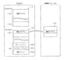
次に、本実施形態のRAM55及び不揮発性メモリー56のうち要部について、図5に基づき説明する。
図5に示すように、不揮発性メモリー56は、第1の記憶手段の一例としてのROM140を有しており、該ROM140には、インクカートリッジICの適切性を検査するための検査プログラム(処理データ)が予め記憶されている。RAM55は、複数(例えば2つ)のメモリーを有している。例えば、RAM55は、第1メモリー141と、第2の記憶手段の一例としての第2メモリー142とを有している。第1メモリー141は、一例として、SDRAM(Synchronous DRAM)であり、その先頭アドレスは、「50000000(16進数)」に設定されている。また、第2メモリー142は、一例として、DDR2(Double Data Rate 2)−SDRAMであり、その先頭アドレスは、「60000000(16進数)」に設定されている。
Next, main parts of the RAM 55 and the nonvolatile memory 56 of the present embodiment will be described with reference to FIG.
As shown in FIG. 5, the non-volatile memory 56 includes a ROM 140 as an example of a first storage unit. The ROM 140 includes an inspection program (processing data) for inspecting the suitability of the ink cartridge IC. ) Is stored in advance. The RAM 55 has a plurality of (for example, two) memories. For example, the RAM 55 includes a first memory 141 and a second memory 142 as an example of a second storage unit. The first memory 141 is, for example, an SDRAM (Synchronous DRAM), and its head address is set to “50000000 (hexadecimal number)”. The second memory 142 is, for example, a DDR2 (Double Data Rate 2) -SDRAM, and its head address is set to “60000000 (hexadecimal number)”.

第1メモリー141には、メカコントローラー43を介してメカニカル機構部44を駆動させるための各種プログラムが記憶される第1領域143と、プリンター11の動作中に各種情報が適宜書き込まれる第2領域144とが形成されている。第2領域144は、第1領域143の最終アドレスの次のアドレス以降に位置している。   The first memory 141 stores a first area 143 in which various programs for driving the mechanical mechanism unit 44 via the mechanical controller 43 are stored, and a second area 144 in which various information is appropriately written during the operation of the printer 11. And are formed. The second area 144 is located after the address next to the last address of the first area 143.

第2メモリー142には、検査プログラムが書き込まれる第1領域(データ領域)145と、画像バッファー88とが形成されている。第1領域145は、第2メモリー142の先頭に配置されると共に、画像バッファー88は、第2メモリー142の最終アドレスを含む位置に位置している。第1領域145には、プリンター11の電源がオンになった場合にROM140に記憶される検査プログラムがCPU53によって書き込まれる。   In the second memory 142, a first area (data area) 145 where an inspection program is written and an image buffer 88 are formed. The first area 145 is arranged at the head of the second memory 142, and the image buffer 88 is located at a position including the final address of the second memory 142. In the first area 145, the CPU 53 writes an inspection program stored in the ROM 140 when the printer 11 is turned on.

画像バッファー88は、プレーンバッファー88aと、ヘッドイメージバッファー88bと、受信バッファー88cとを含んでいる。プレーンバッファー88aは、各種割付処理(マイクロウィーブ処理)及び縦横変換処理などの必要な画像処理が施される前のデータが格納される領域であるとともに、ヘッドイメージバッファー88bは、各種画像処理が施されたヘッド制御データが格納される領域である。さらに、受信バッファー88cは、ホスト制御部125側から受信した印刷データが格納される領域である。ちなみに、ホスト装置120側からの印刷データの受信時に受信バッファー88cがオーバーフローを起こした場合には、第2メモリー142の先頭アドレスを含んだ第1領域145に、印刷データの一部が格納される。その結果、第1領域145に元々書き込まれていたデータが書き換えられてしまう。   The image buffer 88 includes a plane buffer 88a, a head image buffer 88b, and a reception buffer 88c. The plane buffer 88a is an area in which data before necessary image processing such as various assignment processing (microweave processing) and vertical / horizontal conversion processing is stored, and the head image buffer 88b performs various image processing. This is an area for storing the head control data. Further, the reception buffer 88c is an area for storing print data received from the host controller 125 side. Incidentally, when the reception buffer 88c overflows when the print data is received from the host device 120, a part of the print data is stored in the first area 145 including the start address of the second memory 142. . As a result, the data originally written in the first area 145 is rewritten.

次に、インク管理部90の要部について図6に基づき説明する。
図6に示すように、インク管理部90は、インク残量演算部98に加え、判定部150、リード部151及び検査部152をさらに有している。
Next, the main part of the ink management unit 90 will be described with reference to FIG.
As shown in FIG. 6, the ink management unit 90 further includes a determination unit 150, a lead unit 151, and an inspection unit 152 in addition to the ink remaining amount calculation unit 98.

判定部150は、第2メモリー142の第1領域145に記憶される検査プログラムが正常であるか否かを判定する。第2メモリー142の第1領域145には、プリンター11の電源がオンになった場合に、ROM140の検査プログラムが書き込まれる。換言すると、第1領域145に記憶される検査プログラムは、ROM140に記憶される検査プログラム(「オリジナルプログラム」ともいう。)と同一であるはずである。そこで、一例として、判定部150は、第1領域145に記憶される検査プログラムの一部(例えば、先頭の一部分)と、ROM140に記憶される検査プログラムの一部(例えば、先頭の一部分)とが同一である場合には正常であると判定し、同一ではない場合には検査プログラムが正常ではないと判定する。そして、判定部150は、第1領域145に記憶される検査プログラムの少なくとも一部が書き換えられたと判定した場合には、その旨をリード部151に出力する。したがって、本実施形態では、判定部150が、判定手段として機能する。なお、このように検査プログラムの少なくとも一部が他のデータに書き換えられたことを、「検査プログラムに異常が発生した」ということとする。   The determination unit 150 determines whether or not the inspection program stored in the first area 145 of the second memory 142 is normal. In the first area 145 of the second memory 142, the inspection program of the ROM 140 is written when the printer 11 is turned on. In other words, the inspection program stored in the first area 145 should be the same as the inspection program stored in the ROM 140 (also referred to as “original program”). Therefore, as an example, the determination unit 150 includes a part of the inspection program stored in the first area 145 (for example, a part of the head) and a part of the inspection program stored in the ROM 140 (for example, a part of the head). Are the same, it is determined that the inspection program is not normal. If the determination unit 150 determines that at least a part of the inspection program stored in the first area 145 has been rewritten, the determination unit 150 outputs a message to that effect to the read unit 151. Therefore, in this embodiment, the determination unit 150 functions as a determination unit. It should be noted that the fact that at least a part of the inspection program is rewritten with other data in this way is referred to as “an abnormality has occurred in the inspection program”.

リード部151は、判定部150から検査プログラムが異常である旨が入力された場合に、ROM140に記憶される検査プログラムを第2メモリー142の第1領域145に再度書き込ませる第2の処理を行う。この点で、本実施形態では、リード部151が、第2の処理手段として機能する。なお、リード部151は、プリンター11の電源がオンになった場合にも、ROM140に記憶される検査プログラムを、第2メモリー142の第1領域145に書き込ませる。   The lead unit 151 performs a second process for causing the inspection program stored in the ROM 140 to be rewritten in the first area 145 of the second memory 142 when the determination unit 150 inputs that the inspection program is abnormal. . In this regard, in the present embodiment, the lead portion 151 functions as a second processing unit. Note that the read unit 151 causes the inspection program stored in the ROM 140 to be written in the first area 145 of the second memory 142 even when the printer 11 is turned on.

検査部152は、第1領域145に記憶される検査プログラムが正常である場合に、インクカートリッジICの適切性を判断(チェック)するチェック処理(第1の処理)を行う。この点で、本実施形態では、検査部152が、第1の処理手段として機能する。   When the inspection program stored in the first area 145 is normal, the inspection unit 152 performs a check process (first process) for determining (checking) the suitability of the ink cartridge IC. In this regard, in the present embodiment, the inspection unit 152 functions as a first processing unit.

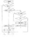
次に、インク管理部90が実行するインク検査処理ルーチンについて、図7に示すフローチャートに基づき説明する。
さて、インク管理部90は、インク検査処理ルーチンを予め設定された所定周期毎に行う。初めのステップS100において、インク管理部90は、インクカートリッジICが交換されたか否かを判定する。マスター側で管理するインクカートリッジIC1〜IC4が交換された場合、マスター側コントローラー41は、インクカートリッジIC1〜IC4の少なくとも一つが交換された旨を、通信I/F部87を通じてスレーブ側コントローラー42に送信する。同様に、スレーブ側で管理するインクカートリッジIC5〜IC8が交換された場合、スレーブ側コントローラー42は、インクカートリッジIC5〜IC8の少なくとも一つが交換された旨を、通信I/F部87を通じてマスター側コントローラー41に送信する。そのため、マスター側のインク管理部90は、スレーブ側で管理するインクカートリッジIC5〜IC8の交換も検知できると共に、スレーブ側のインク管理部90は、マスター側で管理するインクカートリッジIC1〜IC4の交換も検知できる。そのため、ステップS100の判定結果は、マスター側でもスレーブ側でも同一の判定結果となる。そして、インク管理部90は、インクカートリッジICが交換されていない場合(ステップS100;NO)にはインク検査処理ルーチンを終了する一方、インクカートリッジICが交換された場合(ステップS100;YES)にはその処理を次のステップS110に移行する。
Next, an ink inspection processing routine executed by the ink management unit 90 will be described based on the flowchart shown in FIG.
The ink management unit 90 performs an ink inspection processing routine at predetermined intervals set in advance. In the first step S100, the ink management unit 90 determines whether or not the ink cartridge IC has been replaced. When the ink cartridges IC1 to IC4 managed on the master side are replaced, the master controller 41 transmits to the slave controller 42 through the communication I / F unit 87 that at least one of the ink cartridges IC1 to IC4 has been replaced. To do. Similarly, when the ink cartridges IC5 to IC8 managed on the slave side are replaced, the slave side controller 42 notifies the master side controller through the communication I / F unit 87 that at least one of the ink cartridges IC5 to IC8 has been replaced. 41. Therefore, the ink management unit 90 on the master side can detect the replacement of the ink cartridges IC5 to IC8 managed on the slave side, and the ink management unit 90 on the slave side can also replace the ink cartridges IC1 to IC4 managed on the master side. It can be detected. Therefore, the determination result in step S100 is the same determination result on both the master side and the slave side. Then, the ink management unit 90 ends the ink inspection processing routine when the ink cartridge IC has not been replaced (step S100; NO), whereas when the ink cartridge IC has been replaced (step S100; YES). The process proceeds to the next step S110.

ステップS110において、インク管理部90は、第2メモリー142の第1領域145に記憶される検査プログラムが正常であるか否かを判定する。そして、インク管理部90は、第1領域145に記憶される検査プログラムが正常である場合(ステップS110;YES)にはその処理を後述するステップS115に移行する一方、正常ではない場合(ステップS110;NO)にはその処理を後述するステップS120に移行する。したがって、本実施形態では、ステップS110が、判定ステップに相当する。   In step S110, the ink management unit 90 determines whether or not the inspection program stored in the first area 145 of the second memory 142 is normal. Then, when the inspection program stored in the first area 145 is normal (step S110; YES), the ink management unit 90 shifts the process to step S115, which will be described later, whereas when the inspection program is not normal (step S110). NO), the process proceeds to step S120 described later. Therefore, in this embodiment, step S110 corresponds to a determination step.

ここで、第1領域145に記憶される検査プログラムが異常となる場合の一例について説明する。第2メモリー142の第1領域145には、本来、検査プログラム以外の他のコードが書き込まれることはないはずである。しかし、コントローラー41,42は、設計者やユーザーの予期しない動作を行う可能性がある。一例として、ファームプログラム内などにバグが存在する場合、該バグに基づく誤作動が発生し得る。こうしたバグに基づく誤作動によって、例えば、本来は受信バッファー88cに格納させるべきデータが、第2メモリー142の第1領域145に書き込まれたり、他のデータ領域に書き込むべきデータが、第2メモリー142の第1領域145に書き込まれたりすることがある。これは、指定するアドレスの下位側が誤って「0000(16進数)」に設定されたことにより発生し得る。また、第1メモリー141の第2領域144がオーバーフローを起こし、本来は第1メモリー141の第2領域144に格納すべきデータが、第2メモリー142の第1領域145に書き込まれることがある。こうした場合には、第2メモリー142の第1領域145に書き込まれた検査プログラムが異常となり得る。   Here, an example in which the inspection program stored in the first area 145 becomes abnormal will be described. In the first area 145 of the second memory 142, codes other than the inspection program should not be written. However, the controllers 41 and 42 may perform an unexpected operation of the designer or user. As an example, if a bug exists in a farm program or the like, a malfunction based on the bug may occur. Due to such a malfunction based on the bug, for example, data that should be stored in the reception buffer 88c is written to the first area 145 of the second memory 142, or data to be written to another data area is stored in the second memory 142. May be written to the first area 145. This can occur when the lower side of the address to be specified is erroneously set to “0000 (hexadecimal number)”. Further, the second area 144 of the first memory 141 may overflow, and data that should originally be stored in the second area 144 of the first memory 141 may be written to the first area 145 of the second memory 142. In such a case, the inspection program written in the first area 145 of the second memory 142 may become abnormal.

ステップS115において、インク管理部90は、第2メモリー142の第1領域145に記憶される検査プログラムが正常であるため、再書き込みフラグFLG2をオフにセットし、その処理を後述するステップS140に移行する。   In step S115, since the inspection program stored in the first area 145 of the second memory 142 is normal, the ink management unit 90 sets the rewrite flag FLG2 to OFF, and the process proceeds to step S140 described later. To do.

一方、ステップS120において、インク管理部90は、サブタンク残量フラグFLG1がオンであるか否かを判定する。このサブタンク残量フラグFLG1は、詳しくは後述するが、ホスト装置120から受信した印刷データに基づいた印刷時におけるインク使用量の推定値が、サブタンク67内のインク残量未満である場合にはオンにセットされ、インク使用量の推定値がサブタンク67内のインク残量以上である場合にはオフにセットされるフラグである。そして、インク管理部90は、サブタンク残量フラグFLG1がオフである場合(ステップS120;NO)には、サブタンク67内のインク残量が少ないと判断し、その処理を後述するステップS130に移行する。一方、インク管理部90は、サブタンク残量フラグFLG1がオンである場合(ステップS120;YES)には、サブタンク67内のインク残量が多いと判断し、その処理を次のステップS125に移行する。   On the other hand, in step S120, the ink management unit 90 determines whether or not the sub tank remaining amount flag FLG1 is ON. As will be described in detail later, the sub tank remaining amount flag FLG1 is turned on when the estimated value of ink usage during printing based on the print data received from the host device 120 is less than the remaining amount of ink in the sub tank 67. This flag is set to OFF when the estimated value of ink usage is equal to or greater than the remaining amount of ink in the sub-tank 67. When the sub tank remaining amount flag FLG1 is OFF (step S120; NO), the ink management unit 90 determines that the remaining amount of ink in the sub tank 67 is small, and the process proceeds to step S130 described later. . On the other hand, if the sub tank remaining amount flag FLG1 is ON (step S120; YES), the ink management unit 90 determines that the remaining amount of ink in the sub tank 67 is large, and shifts the processing to the next step S125. .

ステップS125において、インク管理部90は、印刷中であるか否かを判定する。そして、インク管理部90は、印刷中である場合(ステップS125;YES)にはインク検査処理ルーチンを一旦終了し、印刷中ではない場合(ステップS125;NO)にはその処理を次のステップS130に移行する。   In step S125, the ink management unit 90 determines whether printing is in progress. Then, the ink management unit 90 ends the ink inspection processing routine once when printing is in progress (step S125; YES), and when not printing (step S125; NO), the processing is performed at the next step S130. Migrate to

ステップS130において、インク管理部90は、再書き込み処理(第2の処理)を行う。したがって、本実施形態では、ステップS130が、第2のステップに相当する。次のステップS135において、インク管理部90は、再書き込みフラグFLG2をオンにセットし、その処理を次のステップS140に移行する。すなわち、本実施形態では、印刷が行われていない場合(印刷終了後も含む。)に、第2の処理が行われる。   In step S130, the ink management unit 90 performs a rewriting process (second process). Therefore, in the present embodiment, step S130 corresponds to the second step. In the next step S135, the ink management unit 90 sets the rewrite flag FLG2 to ON, and proceeds to the next step S140. That is, in the present embodiment, the second process is performed when printing is not performed (including after printing is completed).

ステップS140において、インク管理部90は、上記チェック処理を行う。すなわち、インク管理部90の検査部152は、第2メモリー142の第1領域145に記憶される検査プログラムを実行し、各インクカートリッジIC1〜IC8の適切性を判断(チェック)するチェック処理を行う。このとき、検査部152は、自身が管理する全てのインクカートリッジICに対してチェック(検査)を行ってもよいし、今回交換されたインクカートリッジICにのみチェックを行ってもよい。そして、検査部152は、不適切カートリッジの存在を検知した場合には、その旨を示すエラーコードをメカ制御部83に出力する。その後、インク管理部90は、インク検査処理ルーチンを終了する。したがって、本実施形態では、ステップS140が、第1のステップに相当する。   In step S140, the ink management unit 90 performs the above check process. That is, the inspection unit 152 of the ink management unit 90 executes an inspection program stored in the first area 145 of the second memory 142, and performs a check process for determining (checking) the appropriateness of each of the ink cartridges IC1 to IC8. . At this time, the inspection unit 152 may check (inspect) all the ink cartridge ICs managed by the inspection unit 152, or may check only the ink cartridge ICs replaced this time. When the inspection unit 152 detects the presence of an inappropriate cartridge, the inspection unit 152 outputs an error code indicating that fact to the mechanical control unit 83. Thereafter, the ink management unit 90 ends the ink inspection processing routine. Therefore, in the present embodiment, step S140 corresponds to the first step.

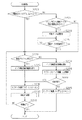
次に、主制御部82が実行する印刷処理ルーチンについて、図8に示すフローチャートに基づき説明する。
さて、主制御部82は、ホスト装置120からの印刷データの受信が完了したタイミングで、印刷処理ルーチンを行う。初めのステップS200において、主制御部82は、再書き込みフラグFLG2がオフであるか否かを判定する。このとき、マスター側の主制御部82は、スレーブ側の再書き込みフラグFLG2がオフであるか否かの情報を通信I/F部87を介して要求し、スレーブ側の再書き込みフラグFLG2を取得する。同様に、スレーブ側の主制御部82は、マスター側の再書き込みフラグFLG2がオフであるか否かの情報を通信I/F部87を介して要求し、マスター側の再書き込みフラグFLG2を取得する。そして、主制御部82は、マスター側及びスレーブ側の各再書き込みフラグFLG2が共にオフである場合(ステップS200;YES)には、その処理を後述するステップS220に移行する。これは、マスター側でもスレーブ側でも、第1メモリー141の第1領域145に書き込まれた検査プログラムが異常ではない、又は異常が検知されていないと判断されたためである。一方、主制御部82は、マスター側及びスレーブ側のうち少なくとも一方の再書き込みフラグFLG2がオンである場合には、その処理を次のステップS205に移行する。これは、マスター側及びスレーブ側のうち少なくとも一方で、第1メモリー141の第1領域145に書き込まれた検査プログラムの異常が検知されたためである。
Next, a print processing routine executed by the main control unit 82 will be described based on the flowchart shown in FIG.
The main control unit 82 performs a print processing routine at a timing when reception of print data from the host device 120 is completed. In the first step S200, the main control unit 82 determines whether or not the rewrite flag FLG2 is off. At this time, the master-side main control unit 82 requests information on whether or not the slave-side rewrite flag FLG2 is OFF via the communication I / F unit 87, and acquires the slave-side rewrite flag FLG2. To do. Similarly, the slave-side main control unit 82 requests information on whether or not the master-side rewrite flag FLG2 is OFF via the communication I / F unit 87, and acquires the master-side rewrite flag FLG2. To do. When the master side and slave side rewrite flags FLG2 are both OFF (step S200; YES), the main control unit 82 shifts the process to step S220 described later. This is because it is determined that the inspection program written in the first area 145 of the first memory 141 is not abnormal or no abnormality is detected on either the master side or the slave side. On the other hand, when at least one rewrite flag FLG2 of the master side and the slave side is on, the main control unit 82 shifts the process to the next step S205. This is because an abnormality in the inspection program written in the first area 145 of the first memory 141 is detected on at least one of the master side and the slave side.

ステップS205において、主制御部82は、上記ステップS140のチェック処理の開始前から、次回用の印刷データの受信が開始されていたか否かを判定する。そして、主制御部82は、次回用の印刷データを受信していない場合(ステップS205;NO)にはその処理を後述するステップS220に移行する一方、次回用の印刷データの受信が開始されていた場合(ステップS205;YES)にはその処理を次のステップS210に移行する。   In step S205, the main control unit 82 determines whether or not reception of print data for the next time has been started before the start of the check process in step S140. When the next print data has not been received (step S205; NO), the main control unit 82 shifts the process to step S220, which will be described later, while reception of the next print data has started. If YES (step S205; YES), the process proceeds to the next step S210.

ステップS210において、主制御部82は、ホスト装置120側に次回用の印刷データの送信を再要求する。次のステップS215において、主制御部82は、次回用の印刷データの受信が完了したか否かを判定する。そして、主制御部82は、次回用の印刷データの受信が完了するまでステップS210の判定処理を繰り返し、次回用の印刷データの受信が完了した場合(ステップS215;YES)には、その処理を次のステップS220に移行する。   In step S210, the main control unit 82 re-requests the host device 120 side to transmit print data for the next time. In the next step S215, the main control unit 82 determines whether or not reception of print data for the next time is completed. Then, the main control unit 82 repeats the determination process of step S210 until reception of the next print data is completed, and when reception of the next print data is completed (step S215; YES), the process is performed. Control proceeds to the next step S220.

ステップS220において、主制御部82は、現時点で、第2メモリー142の第1領域145に書き込まれた検査プログラムが正常であるか否かを、インク管理部90に問い合わせて判定する。そして、主制御部82は、検査プログラムが正常である場合(ステップS220;YES)にはその処理を次のステップS225に移行する一方、検査プログラムが異常である場合(ステップS220;NO)にはその処理を後述するステップS250に移行する。   In step S220, the main control unit 82 inquires of the ink management unit 90 to determine whether or not the inspection program written in the first area 145 of the second memory 142 is normal at this time. When the inspection program is normal (step S220; YES), the main control unit 82 shifts the process to the next step S225, while when the inspection program is abnormal (step S220; NO). The process proceeds to step S250 described later.

ステップS225において、主制御部82は、インク供給装置39の駆動を許可する。次のステップS230において、主制御部82は、サブタンク残量フラグFLG1をオンにセットする。そして、次のステップS235において、主制御部82は、印刷を許可する旨をメカ制御部83に出力する印刷許可処理を行う。次のステップS240において、主制御部82は、印刷が終了したか否かを判定する。そして、主制御部82は、印刷が終了した場合(ステップS240;YES)には印刷処理ルーチンを終了する一方、印刷中である場合(ステップS240;NO)にはその処理を前述したステップS220に移行する。第2メモリー142の第1領域145の検査プログラムが正常である場合には、インク供給装置39の駆動が許可された状態、即ちインクカートリッジIC1〜IC8からサブタンク67にインクを供給させつつシート13に対して印刷が行われる。   In step S225, the main controller 82 permits the ink supply device 39 to be driven. In next step S230, main controller 82 sets sub-tank remaining amount flag FLG1 to ON. In the next step S235, the main control unit 82 performs a print permission process for outputting to the mechanical control unit 83 that printing is permitted. In the next step S240, the main control unit 82 determines whether printing has been completed. Then, the main control unit 82 ends the print processing routine when the printing is finished (step S240; YES), while if the printing is in progress (step S240; NO), the process goes to the above-described step S220. Transition. When the inspection program in the first area 145 of the second memory 142 is normal, the ink supply device 39 is allowed to be driven, that is, the ink is supplied to the subtank 67 from the ink cartridges IC1 to IC8. On the other hand, printing is performed.

ステップS250において、主制御部82は、インク供給装置39の駆動を禁止する。すなわち、第2メモリー142の第1領域145の検査プログラムが異常である場合には、インクカートリッジIC1〜IC8からサブタンク67へのインク供給が禁止される。次のステップS255において、主制御部82は、各サブタンク67内におけるインク残量Izを取得する。このとき、マスター側コントローラー41の主制御部82は、スレーブ側コントローラー42側から該スレーブ側コントローラー42で管理するサブタンク67のインク残量Izも取得する。同様に、スレーブ側コントローラー42の主制御部82は、マスター側コントローラー41側から該マスター側コントローラー41で管理するサブタンク67のインク残量Izも取得する。   In step S <b> 250, the main control unit 82 prohibits driving of the ink supply device 39. That is, when the inspection program in the first area 145 of the second memory 142 is abnormal, ink supply from the ink cartridges IC1 to IC8 to the sub tank 67 is prohibited. In the next step S <b> 255, the main control unit 82 acquires the ink remaining amount Iz in each sub tank 67. At this time, the main control unit 82 of the master-side controller 41 also acquires the remaining ink amount Iz of the sub tank 67 managed by the slave-side controller 42 from the slave-side controller 42 side. Similarly, the main control unit 82 of the slave-side controller 42 also acquires the ink remaining amount Iz of the sub tank 67 managed by the master-side controller 41 from the master-side controller 41 side.

次のステップS260において、主制御部82は、各サブタンク67内のインク残量Izだけで、受信した印刷データに基づいた印刷が可能であるか否かを判定する。そして、主制御部82は、印刷可能と判定した場合(ステップS260;YES)にはその処理を前述したステップS230に移行する。すなわち、第2メモリー142の第1領域145の検査プログラムが異常である場合には、サブタンク67内に貯留されるインクのみで、シート13に対して印刷が行われる。一方、主制御部82は、印刷不能と判定した場合(ステップS260;NO)にはその処理を次のステップS265に移行する。   In the next step S260, the main control unit 82 determines whether printing based on the received print data is possible with only the ink remaining amount Iz in each sub tank 67. If the main control unit 82 determines that printing is possible (step S260; YES), the process proceeds to step S230 described above. That is, when the inspection program in the first area 145 of the second memory 142 is abnormal, printing is performed on the sheet 13 with only the ink stored in the sub tank 67. On the other hand, when the main control unit 82 determines that printing is not possible (step S260; NO), the main control unit 82 shifts the processing to the next step S265.

ステップS265において、主制御部82は、サブタンク残量フラグFLG1をオフにセットし、その後、印刷を行わせることなく、印刷処理ルーチンを終了する。すなわち、印刷が中止される。   In step S265, the main control unit 82 sets the sub-tank remaining amount flag FLG1 to OFF, and thereafter ends the print processing routine without performing printing. That is, printing is stopped.

上記実施形態によれば、以下のような効果を得ることができる。
(1)第2メモリー142の第1領域145に書き込まれた検査プログラムの少なくとも一部が書き換えられた場合には、上記チェック処理が行われない。そのため、書き換えられた検査プログラム、即ち異常と診断された検査プログラムの実行を回避でき、プリンター11の制御装置Cの誤作動を抑制できる。
According to the above embodiment, the following effects can be obtained.
(1) When at least part of the inspection program written in the first area 145 of the second memory 142 is rewritten, the above check process is not performed. Therefore, execution of the rewritten inspection program, that is, the inspection program diagnosed as abnormal can be avoided, and malfunction of the control device C of the printer 11 can be suppressed.

(2)印刷中では、第2メモリー142の第1領域145に書き込まれた検査プログラムが誤って書き換えられる可能性がある。そのため、印刷中に、ROM140に記憶される検査プログラムを第2メモリー142の第1領域145に再度書き込ませたとしても、第1領域145に書き込まれた検査プログラムが再び書き換えられる可能性がある。そこで、本実施形態では、印刷終了後に、ROM140に記憶される検査プログラムが第2メモリー142の第1領域145に再度書き込まれる。その結果、印刷中に印刷に直接関係のないデータの書き換えが行われることが抑制され、印刷時においてプリンター11を正常に動作させることができる。   (2) During printing, the inspection program written in the first area 145 of the second memory 142 may be erroneously rewritten. Therefore, even if the inspection program stored in the ROM 140 is rewritten in the first area 145 of the second memory 142 during printing, the inspection program written in the first area 145 may be rewritten again. Therefore, in the present embodiment, the inspection program stored in the ROM 140 is rewritten in the first area 145 of the second memory 142 after the end of printing. As a result, rewriting of data not directly related to printing is suppressed during printing, and the printer 11 can be operated normally during printing.

また、印刷が完了してから正常な検査プログラムの実行によってインクカートリッジICの適切性を判断するチェック処理が行われるため、不適切カートリッジが有るか否かを適切に検査できる。   In addition, since a check process for determining the appropriateness of the ink cartridge IC is performed by executing a normal inspection program after printing is completed, it is possible to appropriately inspect whether there is an inappropriate cartridge.

(3)第2メモリー142の第1領域145に書き込まれた検査プログラムが異常である場合には、インク供給装置39の駆動が停止され、インクカートリッジICからサブタンク67にインクが供給されなくなる。すると、サブタンク67に貯留されるインクを用いてシート13に印刷を行うことになる。しかし、サブタンク67内のインク残量Izだけでは、印刷を完了させることができないおそれがある。この場合、シート13への印刷が中止される。そのため、シート13への印刷が中途半端な状態で停止させる可能性を抑制できる。   (3) If the inspection program written in the first area 145 of the second memory 142 is abnormal, the drive of the ink supply device 39 is stopped and ink is not supplied from the ink cartridge IC to the sub tank 67. Then, printing is performed on the sheet 13 using the ink stored in the sub tank 67. However, there is a possibility that the printing cannot be completed only with the ink remaining amount Iz in the sub tank 67. In this case, printing on the sheet 13 is stopped. Therefore, it is possible to suppress the possibility of stopping printing on the sheet 13 in a halfway state.

こうして印刷が中止された場合には、ROM140に記憶される検査プログラムが第2メモリー142の第1領域145に再度書き込まれ、検査プログラムに基づいたチェック処理が行われる。そして、検査の結果、不適切カートリッジがない場合には、ホスト装置120側から印刷データが再受信されると共に、インク供給装置39の駆動が許可される。この状態で印刷が開始される。したがって、インクカートリッジIC1〜IC8の検査を適切に行うことができると共に、シート13に対して印刷を適切に行うことができる。   When printing is stopped in this manner, the inspection program stored in the ROM 140 is rewritten in the first area 145 of the second memory 142, and a check process based on the inspection program is performed. If there is no inappropriate cartridge as a result of the inspection, the print data is received again from the host device 120 side and the drive of the ink supply device 39 is permitted. Printing is started in this state. Therefore, the ink cartridges IC1 to IC8 can be properly inspected, and the sheet 13 can be appropriately printed.

(4)第2メモリー142の第1領域145に書き込まれた検査プログラムが異常である場合には、ROM140に記憶される検査プログラムが第2メモリー142の第1領域145に再度書き込まれ、検査プログラムに基づいたチェック処理が行われる。第2メモリー142の第1領域145における検査プログラムの再書き込みが行われる前から、次回用の印刷データの受信が開始されていた場合には、第1領域145に検査プログラムを再度書き込むことによって、受信した次回用の印刷データの少なくとも一部が、検査プログラムの一部に書き換えられる可能性がある。これは、バグなどの原因によって、印刷データの一部が第2メモリー142の第1領域145に書き込まれている可能性があるためである。そこで、本実施形態では、第1領域145に再度書き込まれた検査プログラムに基づいたチェック処理の実行後には、ホスト装置120側に対して印刷データの再送信が要求される。そして、再送信された印刷データに基づいて印刷が行われる。そのため、シート13に適切な画像を印刷させることができる。   (4) If the inspection program written in the first area 145 of the second memory 142 is abnormal, the inspection program stored in the ROM 140 is rewritten in the first area 145 of the second memory 142, and the inspection program Check processing based on the above is performed. If reception of print data for the next time has started before rewriting of the inspection program in the first area 145 of the second memory 142, the inspection program is written again in the first area 145, There is a possibility that at least a part of the received print data for the next time is rewritten to a part of the inspection program. This is because part of the print data may be written in the first area 145 of the second memory 142 due to a bug or the like. Therefore, in the present embodiment, after executing the check process based on the inspection program written again in the first area 145, the host apparatus 120 is requested to retransmit the print data. Then, printing is performed based on the retransmitted print data. Therefore, an appropriate image can be printed on the sheet 13.

(5)本実施形態では、インクカートリッジICが交換された場合に、第2メモリー142の第1領域145の検査プログラムが正常であるか否かが判定される。そして、正常ではないと判定された場合には、印刷の終了後などに、第1領域145に検査プログラムが再度書き込まれ、該検査プログラムに基づいて不適切カートリッジが存在するか否かが検査される。したがって、インクカートリッジICが交換された場合には、不適切カートリッジが存在するか否かを確実に検査することができる。   (5) In this embodiment, when the ink cartridge IC is replaced, it is determined whether or not the inspection program in the first area 145 of the second memory 142 is normal. If it is determined that it is not normal, the inspection program is written again in the first area 145 after the end of printing or the like, and it is inspected whether or not there is an inappropriate cartridge based on the inspection program. The Therefore, when the ink cartridge IC is replaced, it can be reliably inspected whether or not there is an inappropriate cartridge.

(6)また、本実施形態の制御装置Cは、複数のコントローラー41,42を備えており、各コントローラー41,42で検査プログラムに基づいたインクカートリッジIC1〜IC8の検査が行われる。このとき、マスター側(又はスレーブ側)で第2メモリー142の第1領域145における検査プログラムの異常が検知された場合には、その情報がスレーブ側(又はマスター側)にも通知される。そして、各コントローラー41,42で、第2メモリー142の第1領域145における検査プログラムの再書き込みが行われる。また、印刷データの再要求を行う場合でも、コントローラー41,42の各々が印刷データの再要求を行う。すなわち、各コントローラー41,42は、互いに同期をとりつつ、各処理を行っている。したがって、各コントローラー41,42が個別に各種処理を行う場合と比較して、シート13対する印刷不良の発生する可能性を低減することができる。   (6) In addition, the control device C of the present embodiment includes a plurality of controllers 41 and 42, and the controllers 41 and 42 inspect the ink cartridges IC1 to IC8 based on the inspection program. At this time, when an abnormality in the inspection program in the first area 145 of the second memory 142 is detected on the master side (or slave side), the information is also notified to the slave side (or master side). Then, each controller 41, 42 rewrites the inspection program in the first area 145 of the second memory 142. Even when re-requesting print data, each of the controllers 41 and 42 re-requests print data. That is, each controller 41, 42 performs each process while synchronizing with each other. Therefore, it is possible to reduce the possibility of occurrence of printing defects on the sheet 13 as compared with the case where the controllers 41 and 42 individually perform various processes.

(第2の実施形態)
次に、本発明の第2の実施形態を図9に基づき説明する。なお、第2の実施形態は、インク検査処理ルーチンの内容が第1の実施形態と異なっている。したがって、以下の説明においては、第1の実施形態と相違する部分について主に説明するものとし、第1の実施形態と同一又は相当する部材構成には同一符号を付して重複説明を省略するものとする。
(Second Embodiment)
Next, a second embodiment of the present invention will be described with reference to FIG. The second embodiment differs from the first embodiment in the contents of the ink inspection processing routine. Therefore, in the following description, parts different from those of the first embodiment will be mainly described, and the same or corresponding member configurations as those of the first embodiment are denoted by the same reference numerals, and redundant description will be omitted. Shall.

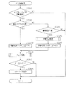
インク管理部90が実行するインク検査処理ルーチンについて、図9に示すフローチャートに基づき説明する。
さて、インク管理部90は、インク検査処理ルーチンを予め設定された所定周期毎に行う。初めのステップS300において、インク管理部90は、上記ステップS100と同様に、インクカートリッジICが交換されたか否かを判定する。そして、インク管理部90は、インクカートリッジICが交換されていない場合(ステップS300;NO)にはインク検査処理ルーチンを終了する一方、インクカートリッジICが交換された場合(ステップS300;YES)にはその処理を次のステップS305に移行する。
The ink inspection processing routine executed by the ink management unit 90 will be described based on the flowchart shown in FIG.
The ink management unit 90 performs an ink inspection processing routine at predetermined intervals set in advance. In the first step S300, the ink management unit 90 determines whether or not the ink cartridge IC has been replaced, as in step S100. Then, the ink management unit 90 ends the ink inspection processing routine when the ink cartridge IC has not been replaced (step S300; NO), whereas when the ink cartridge IC has been replaced (step S300; YES). The process proceeds to the next step S305.

ステップS305において、インク管理部90は、第2メモリー142の第1領域145に記憶される検査プログラムが正常であるか否かを判定する。そして、インク管理部90は、第1領域145に記憶される検査プログラムが正常である場合(ステップS305;YES)にはその処理を次のステップS310に移行する一方、正常ではない場合(ステップS305;NO)にはその処理を後述するステップS320に移行する。したがって、本実施形態では、ステップS305が、判定ステップに相当する。   In step S <b> 305, the ink management unit 90 determines whether or not the inspection program stored in the first area 145 of the second memory 142 is normal. Then, if the inspection program stored in the first area 145 is normal (step S305; YES), the ink management unit 90 proceeds to the next step S310, but if not normal (step S305). ; NO), the process proceeds to step S320 described later. Therefore, in the present embodiment, step S305 corresponds to a determination step.

ステップS310において、インク管理部90は、第1領域145に記憶される検査プログラムが正常であるため、再書き込みフラグFLG2をオフにセットし、その処理を後述するステップS340に移行する。   In step S310, since the inspection program stored in the first area 145 is normal, the ink management unit 90 sets the rewrite flag FLG2 to OFF, and the process proceeds to step S340 described later.

一方、ステップS320において、インク管理部90は、現時点において同時並行で行われる各処理(各タスク)の中で、インクカートリッジIC1〜IC8を検査するチェック処理の優先順位が1番であるか否かを判定する。具体的には、インク管理部90は、メカ制御部83を介して主制御部82に、チェック処理よりも優先順位の高い処理が実行中であるか否かに関する情報を要求する。そして、インク管理部90は、チェック処理の優先順位が1番である場合(ステップS320;YES)にはその処理を後述するステップS325に移行する。一方、インク管理部90は、チェック処理の優先順位が1番ではない場合(ステップS320;NO)にはインク検査処理ルーチンを一旦終了する。   On the other hand, in step S320, the ink management unit 90 determines whether or not the priority of the check process for inspecting the ink cartridges IC1 to IC8 is the first among the processes (tasks) performed in parallel at the present time. Determine. Specifically, the ink management unit 90 requests the main control unit 82 via the mechanical control unit 83 for information regarding whether or not a process having a higher priority than the check process is being executed. Then, if the priority of the check process is No. 1 (step S320; YES), the ink management unit 90 proceeds to step S325 described later. On the other hand, if the priority of the check process is not the first (step S320; NO), the ink management unit 90 once ends the ink inspection process routine.

なお、チェック処理の優先順位よりも高い優先順位の処理(第3の処理)は、一例として、インク消費量を取得する処理が挙げられる。特に印刷中においては、各記録ヘッド29からインクが噴射される。本実施形態では、インク消費量は、インクの噴射回数を色毎に計数し、該計数結果に基づき算出している。そして、このように算出されたインク消費量に基づき、インクカートリッジIC1〜IC8内におけるインク残量が取得される。すなわち、インク消費量の取得は、インクカートリッジIC1〜IC8の交換タイミングをユーザーに報知させるためには非常に重要な処理である。そのため、インク消費量を取得するための処理は、インクカートリッジIC1〜IC8を検査するチェック処理よりも優先順位が高めに設定される。   An example of the process (third process) having a higher priority than the priority of the check process is a process of acquiring ink consumption. In particular, during printing, ink is ejected from each recording head 29. In this embodiment, the ink consumption is calculated based on the counting result by counting the number of ink ejections for each color. Then, based on the ink consumption calculated in this way, the ink remaining amount in the ink cartridges IC1 to IC8 is acquired. That is, the acquisition of the ink consumption is a very important process for notifying the user of the replacement timing of the ink cartridges IC1 to IC8. Therefore, the process for acquiring the ink consumption is set to have a higher priority than the check process for inspecting the ink cartridges IC1 to IC8.

ステップS325において、インク管理部90は、上記ステップS130と同様に、再書き込み処理を行う。したがって、本実施形態では、ステップS325が、第2のステップに相当する。次のステップS330において、インク管理部90は、再書き込みフラグFLG2をオンにセットし、その処理を次のステップS340に移行する。   In step S325, the ink management unit 90 performs rewriting processing in the same manner as in step S130. Therefore, in the present embodiment, step S325 corresponds to the second step. In the next step S330, the ink management unit 90 sets the rewrite flag FLG2 to ON, and proceeds to the next step S340.

ステップS340において、インク管理部90は、上記ステップS140と同様に、チェック処理を行う。したがって、本実施形態では、ステップS325が、第1のステップに相当する。   In step S340, the ink management unit 90 performs a check process as in step S140. Accordingly, in the present embodiment, step S325 corresponds to the first step.

次のステップS350において、インク管理部90は、再書き込みフラグFLG2がオンであるか否かを判定する。そして、インク管理部90は、再書き込みフラグがオフである場合(ステップS350;NO)には、チェック処理(第1の処理)を行うにあたって、再書き込み処理(第2の処理)を行っていないため、インク検査処理ルーチンを一旦終了する。一方、インク管理部90は、再書き込みフラグFLG2がオンである場合(ステップS350;YES)には、チェック処理を行うにあたって、再書き込み処理を行ったため、その処理を次のステップS355に移行する。ステップS355において、インク管理部90は、検査プログラムが異常である旨を示すエラーコードを、メカ制御部83に出力する、即ち報知処理を行う。その後、インク管理部90は、インク検査処理ルーチンを一旦終了する。   In the next step S350, the ink management unit 90 determines whether or not the rewrite flag FLG2 is on. When the rewrite flag is off (step S350; NO), the ink management unit 90 does not perform the rewrite process (second process) when performing the check process (first process). Therefore, the ink inspection processing routine is once ended. On the other hand, if the rewrite flag FLG2 is on (step S350; YES), the ink management unit 90 has performed the rewrite process when performing the check process, and thus proceeds to the next step S355. In step S355, the ink management unit 90 outputs an error code indicating that the inspection program is abnormal to the mechanical control unit 83, that is, performs notification processing. Thereafter, the ink management unit 90 once ends the ink inspection processing routine.

メカ制御部83に出力されたエラーコードは、エラー管理部86に転送される。そして、エラー管理部86は、転送されたエラーコードを含むエラーコマンドを主制御部82に出力する。すると、主制御部82は、印刷を中止させると共に、エラーコマンドをホスト装置120側に送信する。その結果、ホスト装置120のモニター123には、コントローラー41,42内でエラーが発生した旨及び印刷が中止された旨が表示される。   The error code output to the mechanical control unit 83 is transferred to the error management unit 86. Then, the error management unit 86 outputs an error command including the transferred error code to the main control unit 82. Then, the main control unit 82 stops printing and transmits an error command to the host device 120 side. As a result, the monitor 123 of the host device 120 displays that an error has occurred in the controllers 41 and 42 and that printing has been stopped.

したがって、本実施形態では、上記第1の実施形態における効果(1)(5)に加え、以下に示す効果を更に得ることができる。
(7)第2メモリー142の第1領域145の検査プログラムが異常である場合には、第1領域145に検査プログラムが再度書き込まれ、該検査プログラムに基づいて不適切カートリッジが存在するか否かが検査される。したがって、インクカートリッジICが交換された場合には、不適切カートリッジが存在するか否かを確実に検査することができる。
Therefore, in this embodiment, in addition to the effects (1) and (5) in the first embodiment, the following effects can be further obtained.
(7) If the inspection program in the first area 145 of the second memory 142 is abnormal, the inspection program is written again in the first area 145, and whether or not there is an inappropriate cartridge based on the inspection program. Is inspected. Therefore, when the ink cartridge IC is replaced, it can be reliably inspected whether or not there is an inappropriate cartridge.

(8)インクカートリッジIC1〜IC8を検査する処理の優先順位よりも高い優先順位の第3の処理が実行される場合には、該第3の処理が終了するまで、第2メモリー142の第1領域145への検査プログラムの再書き込みが行われない。これは、ファームプログラム内に存在するバグなどに起因して、第3の処理時に取得されたデータが、第2メモリー142の第1領域145内に書き込まれている可能性があるためである。この状態で、第1領域145への検査プログラムの再書き込みを行った場合には、第3の処理時に取得されたデータが消えてしまい、プリンター11の制御に支障をきたすおそれがある。したがって、第3の処理をより正確に実行させることができ、ひいてはプリンター11の誤作動を抑制することができる。   (8) When the third process having a higher priority than the priority of the process for inspecting the ink cartridges IC1 to IC8 is executed, the first of the second memory 142 is continued until the third process is completed. The rewriting of the inspection program to the area 145 is not performed. This is because there is a possibility that data acquired during the third process is written in the first area 145 of the second memory 142 due to a bug or the like existing in the firmware program. In this state, if the inspection program is rewritten to the first area 145, the data acquired during the third process is lost, which may hinder the control of the printer 11. Therefore, the third process can be executed more accurately, and the malfunction of the printer 11 can be suppressed.

(9)第3の処理は、インク消費量を取得する処理である。そのため、第2メモリー142の第1領域145の検査プログラムが異常であるとしても、インク消費量を確実に取得でき、ひいてはインクカートリッジIC1〜IC8内におけるインク残量を取得することができる。すなわち、インクカートリッジIC1〜IC8の交換タイミングをユーザーに適切に報知できる。   (9) The third process is a process for acquiring the ink consumption. Therefore, even if the inspection program in the first area 145 of the second memory 142 is abnormal, the ink consumption amount can be acquired with certainty, and the remaining ink amount in the ink cartridges IC1 to IC8 can be acquired. That is, it is possible to appropriately notify the user of the replacement timing of the ink cartridges IC1 to IC8.

(10)第2メモリー142の第1領域145に検査プログラムが再度書き込まれ、該検査プログラムに基づいた検査の実行後では、コントローラー41,42が正常に動作しないおそれがある。これは、印刷に必要なデータが第2メモリー142の第1領域145に誤って書き込まれている可能性があるためである。そのため、コントローラー41,42内で異常が発生した旨の報知処理が行われる。すなわち、コントローラー41,42で異常が発生したことを、ユーザーに認識させることができる。   (10) After the inspection program is written again in the first area 145 of the second memory 142 and the inspection based on the inspection program is executed, the controllers 41 and 42 may not operate normally. This is because there is a possibility that data necessary for printing is erroneously written in the first area 145 of the second memory 142. Therefore, a notification process that an abnormality has occurred in the controllers 41 and 42 is performed. That is, it is possible to make the user recognize that an abnormality has occurred in the controllers 41 and 42.

なお、上記各実施形態は以下のように変更してもよい。
・第2の実施形態において、インクカートリッジIC1〜IC8の重量を検出するためのセンサーを設け、該センサーからの検出信号に基づきインクカートリッジIC1〜IC8内におけるインク残量を検出する場合などには、インク検査処理ルーチンのステップS320の判定処理を省略してもよい。このように構成しても、インクカートリッジIC1〜IC8内におけるインク残量を好適に検出できる。
In addition, you may change each said embodiment as follows.
In the second embodiment, when a sensor for detecting the weight of the ink cartridges IC1 to IC8 is provided and the remaining amount of ink in the ink cartridges IC1 to IC8 is detected based on the detection signal from the sensor, The determination process in step S320 of the ink inspection process routine may be omitted. Even if comprised in this way, the ink residual amount in the ink cartridges IC1-IC8 can be detected suitably.

・第2の実施形態において、インク検査処理ルーチンを、印刷中には行わない制御構成とした場合には、インク検査処理ルーチンのステップS320の判定処理を省略してもよい。   In the second embodiment, when the ink inspection processing routine is configured to be not performed during printing, the determination processing in step S320 of the ink inspection processing routine may be omitted.

・第1の実施形態において、次回印刷用の印刷データが、今回の印刷が完了してからしか受信されない場合には、印刷処理ルーチンからステップS200,S205,S210,S215の各処理を省略してもよい。   In the first embodiment, when the print data for the next printing is received only after the current printing is completed, the processes of steps S200, S205, S210, and S215 are omitted from the print processing routine. Also good.

・第1の実施形態において、ステップS125の判定結果が肯定になった場合には、検査プログラムが異常であることをユーザーに報知させる処理を行ってもよい。
・各実施形態において、インク検査処理ルーチンのステップS100,S300の判定処理を、インクカートリッジIC1〜IC8の交換を検知したか否かを判断する処理以外の他の処理に変更してもよい。例えば、ステップS100,S300の判定処理を、印刷データを受信したか否かの判定処理にしてもよい。
-In 1st Embodiment, when the determination result of step S125 becomes affirmative, you may perform the process which notifies a user that an inspection program is abnormal.
In each embodiment, the determination processing in steps S100 and S300 of the ink inspection processing routine may be changed to processing other than the processing for determining whether or not the replacement of the ink cartridges IC1 to IC8 is detected. For example, the determination processing in steps S100 and S300 may be determination processing for determining whether print data has been received.

・各実施形態において、第2メモリー142の第1領域145には、所定のタイミングで実行されるプログラムであれば検査プログラム以外の他のプログラムを書き込ませてもよい。   In each embodiment, a program other than the inspection program may be written in the first area 145 of the second memory 142 as long as the program is executed at a predetermined timing.

・各実施形態において、第2メモリー142の第1領域145に書き込まれるプログラムは、その先頭に印刷中止用のコードを含んだプログラムであってもよい。この場合、印刷時に第1領域145に記憶されるデータが読み込まれると、印刷が中止される。そのため、シート13に、ユーザーが意図しない画像が誤って印刷されることを抑制できる。   In each embodiment, the program written in the first area 145 of the second memory 142 may be a program that includes a print cancel code at the head thereof. In this case, when data stored in the first area 145 is read during printing, printing is stopped. Therefore, it is possible to prevent an image that is not intended by the user from being accidentally printed on the sheet 13.

また、第2メモリー142の第1領域145に書き込まれるプログラムは、その先頭に空白データ(即ち、0(2進数)が複数個連続するデータ)を含んだプログラムであってもよい。この場合、印刷時に第1領域145に記憶されるデータが読み込まれても、記録ヘッド29からインクが噴射されない。そのため、シート13に、ユーザーが意図しない画像が誤って印刷されることを抑制できる。   The program written in the first area 145 of the second memory 142 may be a program including blank data (that is, data in which a plurality of 0s (binary numbers) continue) at the head thereof. In this case, ink is not ejected from the recording head 29 even if data stored in the first area 145 is read during printing. Therefore, it is possible to prevent an image that is not intended by the user from being accidentally printed on the sheet 13.

・各実施形態において、第2メモリー142の第1領域145に書き込まれる処理データは、所定の画像をシート13に印刷させるための印刷データであってもよい。
・各実施形態では、第2メモリー142の第1領域145への検査プログラムの再書き込み時には、マスター側とスレーブ側とで同期をとっているが、同期をとらなくてもよい。この場合、スレーブ側のみで検査プログラムが異常である場合には、スレーブ側で検査プログラムの再書き込みが行われる一方、マスター側では検査プログラムの再書き込みが行われない。
In each embodiment, the processing data written in the first area 145 of the second memory 142 may be print data for printing a predetermined image on the sheet 13.
In each embodiment, when the test program is rewritten to the first area 145 of the second memory 142, the master side and the slave side are synchronized, but the synchronization may not be performed. In this case, if the inspection program is abnormal only on the slave side, the inspection program is rewritten on the slave side, while the inspection program is not rewritten on the master side.

・各実施形態において、各コントローラー41,42は、互いに異なる構成であってもよい。例えば、仮想メカコントローラー85は、ダミーメカコン部97を省略した構成であってもよいし、ダミーメカコントローラー95は、仮想メカコン部96を省略した構成であってもよい。   In each embodiment, the controllers 41 and 42 may have different configurations. For example, the virtual mechanical controller 85 may have a configuration in which the dummy mechanical control unit 97 is omitted, and the dummy mechanical controller 95 may have a configuration in which the virtual mechanical control unit 96 is omitted.

・各実施形態において、制御装置Cは、複数(例えば2つ)のスレーブ側コントローラーを備えた構成であってもよい。
・各実施形態において、RAM55は、1つ又は3つ以上の任意数(例えば3つ)のメモリーを含んだ構成であってもよい。また、検査プログラムが書き込まれるデータ領域は、書き換え可能な状態と書き換え不能な状態とをCPU53からの指示によって変更できるデータ領域であってもよいし、常に書き換え可能なデータ領域であってもよい。
In each embodiment, the control device C may have a configuration including a plurality (for example, two) of slave-side controllers.
In each embodiment, the RAM 55 may include one or three or more arbitrary numbers (for example, three) of memories. Further, the data area in which the inspection program is written may be a data area that can be changed between a rewritable state and a non-rewritable state by an instruction from the CPU 53, or may be a data area that is always rewritable.

・各実施形態において、第1領域145は、第2メモリー142の先頭に設けなくてもよい。
・各実施形態において、プリンター11は、複数の記録ヘッド29を備えた構成であれば、シリアル方式のプリンターであってもよいし、印刷時に記録ヘッド29が移動しない所謂ライン方式のプリンターであってもよい。
In each embodiment, the first area 145 may not be provided at the top of the second memory 142.
In each embodiment, the printer 11 may be a serial printer or a so-called line printer in which the recording head 29 does not move during printing as long as the printer 11 includes a plurality of recording heads 29. Also good.

・各実施形態では、プリンター11として、インクジェット式プリンターが採用されているが、インク以外の他の流体を噴射したり吐出したりする流体噴射装置を採用してもよい。また、微小量の液滴を吐出させる液体噴射ヘッド等を備える各種の液体噴射装置に流用可能である。この場合、液滴とは、上記液体噴射装置から吐出される液体の状態を言い、粒状、涙状、糸状に尾を引くものも含むものとする。また、ここでいう液体とは、液体噴射装置が噴射させることができるような材料であればよい。例えば、物質が液相であるときの状態のものであればよく、粘性の高い又は低い液状体、ゾル、ゲル水、その他の無機溶剤、有機溶剤、溶液、液状樹脂、液状金属(金属融液)のような流状体、また物質の一状態としての液体のみならず、顔料や金属粒子などの固形物からなる機能材料の粒子が溶媒に溶解、分散または混合されたものなどを含む。また、液体の代表的な例としては上記実施形態で説明したようなインクや液晶等が挙げられる。ここで、インクとは一般的な水性インクおよび油性インク並びにジェルインク、ホットメルトインク等の各種液体組成物を包含するものとする。液体噴射装置の具体例としては、例えば液晶ディスプレイ、EL(エレクトロルミネッセンス)ディスプレイ、面発光ディスプレイ、カラーフィルタの製造などに用いられる電極材や色材などの材料を分散または溶解のかたちで含む液体を噴射する液体噴射装置が挙げられる。さらに、バイオチップ製造に用いられる生体有機物を噴射する液体噴射装置、精密ピペットとして用いられ試料となる液体を噴射する液体噴射装置、捺染装置やマイクロディスペンサ等であってもよい。さらに、時計やカメラ等の精密機械にピンポイントで潤滑油を噴射する液体噴射装置、光通信素子等に用いられる微小半球レンズ(光学レンズ)などを形成するために紫外線硬化樹脂等の透明樹脂液を基板上に噴射する液体噴射装置、基板などをエッチングするために酸又はアルカリ等のエッチング液を噴射する液体噴射装置を採用してもよい。そして、これらのうちいずれか一種の液体噴射装置に本発明を適用することができる。また、流体は、トナーなどの粉粒体でもよい。なお、本明細書でいう流体には、気体のみからなるものは含まないものとする。   In each embodiment, an ink jet printer is employed as the printer 11, but a fluid ejecting apparatus that ejects or ejects fluid other than ink may be employed. Further, the present invention can be used for various liquid ejecting apparatuses including a liquid ejecting head that ejects a minute amount of liquid droplets. In this case, the droplet refers to the state of the liquid ejected from the liquid ejecting apparatus, and includes liquid droplets having a granular shape, a tear shape, and a thread shape. The liquid here may be any material that can be ejected by the liquid ejecting apparatus. For example, it may be in a state in which the substance is in a liquid phase, such as a liquid with high or low viscosity, sol, gel water, other inorganic solvents, organic solvents, solutions, liquid resins, liquid metals (metal melts ) And liquids as one state of the substance, as well as those obtained by dissolving, dispersing or mixing particles of a functional material made of solid materials such as pigments and metal particles in a solvent. Further, representative examples of the liquid include ink and liquid crystal as described in the above embodiment. Here, the ink includes general water-based inks and oil-based inks, and various liquid compositions such as gel inks and hot-melt inks. As a specific example of the liquid ejecting apparatus, for example, a liquid containing a material such as an electrode material or a coloring material used for manufacturing a liquid crystal display, an EL (electroluminescence) display, a surface emitting display, a color filter, or the like in a dispersed or dissolved state. A liquid ejecting apparatus for ejecting may be used. Further, it may be a liquid ejecting apparatus that ejects a bio-organic matter used for biochip production, a liquid ejecting apparatus that ejects a liquid that is used as a precision pipette and serves as a sample, a printing apparatus, a microdispenser, or the like. In addition, transparent resin liquids such as UV curable resin to form liquid injection devices that pinpoint lubricant oil onto precision machines such as watches and cameras, and micro hemispherical lenses (optical lenses) used in optical communication elements. A liquid ejecting apparatus that ejects a liquid onto the substrate or a liquid ejecting apparatus that ejects an etching solution such as an acid or an alkali to etch the substrate may be employed. The present invention can be applied to any one of these liquid ejecting apparatuses. Further, the fluid may be a granular material such as toner. In addition, the fluid referred to in this specification does not include a fluid consisting only of a gas.

・各実施形態において、プリンター11は、ドットインパクト方式、レーザー方式などの他の印刷方式のプリンターでもよい。
次に、上記各実施形態及び別の実施形態から把握できる技術的思想を以下に追記する。
In each embodiment, the printer 11 may be a printer of another printing method such as a dot impact method or a laser method.
Next, technical ideas that can be grasped from the above embodiments and other embodiments will be added below.

(イ)前記処理データは、前記印刷装置に装着された収容容器を検査するための検査プログラムであり、
前記第1の処理手段は、収容容器の交換後において、前記判定手段によって前記データ領域の前記処理データが書き換えられていないと判定されたときに、前記第1の処理を行うことを特徴とする印刷装置。
(A) The processing data is an inspection program for inspecting a storage container attached to the printing apparatus,
The first processing means performs the first processing when it is determined by the determination means that the processing data in the data area has not been rewritten after replacement of the storage container. Printing device.

(ロ)複数の情報処理装置を備えた情報処理システムにおいて、
前記各情報処理装置は、請求項1〜請求項9のうち何れか一項に記載の情報処理装置であり、
前記各情報処理装置のうち第1の情報処理装置は、自身の前記データ領域に書き込まれた前記処理データが書き換えられたことを前記判定手段によって判定した場合には、その旨を前記第1の情報処理装置とは異なる第2の情報処理装置に送信し、
前記第1の情報処理装置の前記第2の処理手段は、前記処理データが書き換えられた旨を前記第2の情報処理装置に送信した後に、前記第2の処理を行い、
前記第2の情報処理装置の前記第2の処理手段は、前記第1の情報処理装置側から前記処理データが書き換えられた旨を受信した場合に、前記第2の処理を行うことを特徴とする情報処理システム。
(B) In an information processing system including a plurality of information processing devices,
Each said information processing apparatus is an information processing apparatus as described in any one of Claims 1-9,
When the first information processing apparatus among the information processing apparatuses determines that the processing data written in the data area of the information processing apparatus has been rewritten by the determination unit, the first information processing apparatus Transmitting to a second information processing device different from the information processing device,
The second processing means of the first information processing device performs the second processing after transmitting the fact that the processing data has been rewritten to the second information processing device,
The second processing means of the second information processing device performs the second processing when receiving a notification that the processing data has been rewritten from the first information processing device side. Information processing system.

11…印刷装置としてのインクジェット式プリンター、13…印刷媒体としてのシート、29…出力手段を構成する記録ヘッド(印刷ヘッド)、39…出力手段を構成するインク供給装置、41,42…情報処理装置としてのコントローラー、67…出力手段を構成するサブタンク(貯留部)、83…制御手段としてのメカ制御部、120…他の情報処理装置としてのホスト装置、140…第1の記憶手段としてのROM、142…第2の記憶手段としての第2メモリー、145…データ領域としての第1領域、150…判定手段としての判定部、151…第2の処理手段としてのリード部、152…第1の処理手段としての検査部、C…情報処理システムとしての制御装置、IC,IC1〜IC8…収容容器としてのインクカートリッジ、U3,U4…通信手段としてのシリアル通信ポート。   DESCRIPTION OF SYMBOLS 11 ... Inkjet printer as printing device, 13 ... Sheet as printing medium, 29 ... Recording head (printing head) constituting output means, 39 ... Ink supply device constituting output means, 41, 42 ... Information processing device , A sub-tank (storage unit) constituting output means, 83 a mechanical control part as a control means, 120 a host device as another information processing apparatus, 140 a ROM as a first storage means, 142: second memory as second storage means, 145: first area as data area, 150: determination section as determination means, 151: lead section as second processing means, 152: first processing Inspection unit as means, C ... control device as information processing system, IC, IC1 to IC8 ... ink cartridge as container, 3, U4 ... serial communication port as a communication means.

Claims (11)

処理データを記憶する第1の記憶手段と、
前記第1の記憶手段に記憶される前記処理データが書き込まれるデータ領域を有する第2の記憶手段と、
前記データ領域の処理データが書き換えられたか否かを判定する判定手段と、
前記判定手段によって前記データ領域の処理データが書き換えられていないと判定された場合に、前記データ領域に記憶される処理データに基づいた第1の処理を行う第1の処理手段と、
前記判定手段によって前記データ領域の処理データが書き換えられたと判定された場合に、前記第1の処理とは異なる第2の処理を行う第2の処理手段と、を備えることを特徴とする情報処理装置。
First storage means for storing processing data;
Second storage means having a data area in which the processing data stored in the first storage means is written;
Determining means for determining whether or not the processing data of the data area has been rewritten;
First processing means for performing a first process based on the processing data stored in the data area when the determination means determines that the processing data in the data area has not been rewritten;
And a second processing unit for performing a second process different from the first process when the determination unit determines that the processing data in the data area has been rewritten. apparatus.
出力手段による出力態様を制御する制御手段をさらに備え、
前記第2の処理手段は、前記判定手段によって前記データ領域の処理データが書き換えられたと判定された場合において、前記制御手段による前記出力手段の制御の終了後に、前記第1の記憶手段に記憶される処理データを前記データ領域に書き込む前記第2の処理を行うことを特徴とする請求項1に記載の情報処理装置。
It further comprises control means for controlling the output mode by the output means,
The second processing means is stored in the first storage means after the control means finishes controlling the output means when the determination means determines that the processing data in the data area has been rewritten. The information processing apparatus according to claim 1, wherein the second process of writing processing data to be written to the data area is performed.
前記出力手段は、流体を収容する収容容器から供給された流体を一時的に貯留する貯留部と、前記収容容器から前記貯留部に流体を供給する際に駆動する供給装置と、前記貯留部から供給された流体を用いて印刷媒体に印刷を施す印刷ヘッドと、を有しており、
前記制御手段は、
前記判定手段によって前記データ領域の処理データが書き換えられたと判定された場合に、前記供給装置の駆動を禁止し、
この状態で前記貯留部内に貯留される流体の残量が多いと判定した場合には印刷媒体への印刷を行う一方、前記貯留部内に貯留される流体の残量が少ないと判定した場合には印刷媒体への印刷を中止することを特徴とする請求項2に記載の情報処理装置。
The output means includes: a storage unit that temporarily stores fluid supplied from a storage container that stores fluid; a supply device that is driven when fluid is supplied from the storage container to the storage unit; and the storage unit A print head for printing on a print medium using the supplied fluid,
The control means includes
When the determination means determines that the processing data in the data area has been rewritten, the driving of the supply device is prohibited,
In this state, when it is determined that the remaining amount of fluid stored in the storage unit is large, printing on a print medium is performed, whereas when it is determined that the remaining amount of fluid stored in the storage unit is small The information processing apparatus according to claim 2, wherein printing on a print medium is stopped.
前記出力手段を駆動させるために必要な駆動データを他の情報処理装置から受信する通信手段をさらに備え、
前記第1の処理手段は、前記判定手段によって前記データ領域の処理データが書き換えられたと判定された場合には、前記第2の処理手段による前記第2の処理の終了後に前記第1の処理を行い、
前記通信手段は、前記第2の処理手段による前記第2の処理の開始前から前記出力手段を次回駆動させるために必要な駆動データの受信を開始していた場合には、前記第1の処理手段による前記第1の処理の終了後に、前記他の情報処理装置からの駆動データの再送信を要求することを特徴とする請求項2又は請求項3に記載の情報処理装置。
Further comprising communication means for receiving drive data necessary for driving the output means from another information processing apparatus;
The first processing unit performs the first processing after the second processing by the second processing unit is completed when the determination unit determines that the processing data in the data area has been rewritten. Done
If the communication means has started to receive drive data necessary to drive the output means next time before the second process is started by the second processing means, the first process 4. The information processing apparatus according to claim 2, wherein after the first processing by the means is completed, a re-transmission of drive data from the other information processing apparatus is requested. 5.
前記第2の処理手段は、前記判定手段によって前記データ領域の処理データが書き換えられたと判定された場合に、前記第1の記憶手段に記憶される処理データを前記データ領域に書き込む前記第2の処理を行うことを特徴とする請求項1に記載の情報処理装置。 The second processing means writes the processing data stored in the first storage means to the data area when the determination means determines that the processing data in the data area has been rewritten. The information processing apparatus according to claim 1, wherein processing is performed. 前記第2の処理手段は、該第1の処理手段による前記第1の処理よりも優先順位の高い第3の処理が存在する場合には、該第3の処理の実行中に、前記第2の処理を行わないことを特徴とする請求項5に記載の情報処理装置。 When there is a third process having a higher priority than the first process performed by the first processing unit, the second processing unit performs the second process during the execution of the third process. The information processing apparatus according to claim 5, wherein the processing is not performed. 前記第2の処理手段は、前記第3の処理の終了後に前記第2の処理を行い、
その後、前記第1の処理手段は、前記第1の処理を行った後、異常が発生した旨を報知する報知処理を行うことを特徴とする請求項6に記載の情報処理装置。
The second processing means performs the second processing after the end of the third processing,
The information processing apparatus according to claim 6, wherein the first processing unit performs a notification process for notifying that an abnormality has occurred after performing the first process.
流体を用いて印刷媒体に印刷を行う出力手段を制御する情報処理装置であって、
前記第3の処理は、前記出力手段による流体の消費量を取得することを特徴とする請求項7に記載の情報処理装置。
An information processing apparatus that controls output means for printing on a print medium using a fluid,
The information processing apparatus according to claim 7, wherein the third process acquires a consumption amount of fluid by the output unit.
前記処理データは、プログラムであることを特徴とする請求項1〜請求項8のうち何れか一項に記載の情報処理装置。 The information processing apparatus according to claim 1, wherein the processing data is a program. 着脱可能な状態で装着された収容容器から供給された流体を貯留する貯留部、及び該貯留部から供給された流体を用いて印刷媒体に印刷を施す印刷ヘッドを有する出力手段と、
請求項1〜請求項9のうち何れか一項に記載の情報処理装置と、を備えることを特徴とする印刷装置。
An output unit having a storage unit that stores fluid supplied from a storage container that is mounted in a detachable state, and a print head that performs printing on a print medium using the fluid supplied from the storage unit;
A printing apparatus comprising: the information processing apparatus according to claim 1.
処理データを記憶する第1の記憶手段と、前記第1の記憶手段に記憶される前記処理データが書き込まれるデータ領域を有する第2の記憶手段とを備えた情報処理装置におけるデータ管理方法であって、
前記データ領域の処理データが書き換えられたか否かを判定させる判定ステップと、
前記判定ステップで前記データ領域の処理データが書き換えられていないと判定した場合に、前記第2の記憶手段の前記データ領域の処理データに基づいた第1の処理を行わせる第1のステップと、
前記判定ステップで前記データ領域の処理データが書き換えられたと判定した場合には、前記第1の処理とは異なる第2の処理を行わせる第2のステップと、を有することを特徴とするデータ管理方法。
A data management method in an information processing apparatus comprising: a first storage unit that stores processing data; and a second storage unit that includes a data area in which the processing data stored in the first storage unit is written. And
A determination step for determining whether or not the processing data of the data area has been rewritten;
A first step for performing a first process based on the process data in the data area of the second storage means when it is determined in the determination step that the process data in the data area has not been rewritten;
And a second step of performing a second process different from the first process when it is determined in the determination step that the process data in the data area has been rewritten. Method.
JP2010163653A 2010-07-21 2010-07-21 Information processor, printer, and data management method Withdrawn JP2012024957A (en)

Priority Applications (1)

Application Number Priority Date Filing Date Title
JP2010163653A JP2012024957A (en) 2010-07-21 2010-07-21 Information processor, printer, and data management method

Applications Claiming Priority (1)

Application Number Priority Date Filing Date Title
JP2010163653A JP2012024957A (en) 2010-07-21 2010-07-21 Information processor, printer, and data management method

Publications (1)

Publication Number Publication Date
JP2012024957A true JP2012024957A (en) 2012-02-09

Family

ID=45778505

Family Applications (1)

Application Number Title Priority Date Filing Date
JP2010163653A Withdrawn JP2012024957A (en) 2010-07-21 2010-07-21 Information processor, printer, and data management method

Country Status (1)

Country Link
JP (1) JP2012024957A (en)

Cited By (1)

* Cited by examiner, † Cited by third party
Publication number Priority date Publication date Assignee Title
JP2014191265A (en) * 2013-03-28 2014-10-06 Oki Data Corp Image forming apparatus

Citations (6)

* Cited by examiner, † Cited by third party
Publication number Priority date Publication date Assignee Title
JPH0647997A (en) * 1992-07-28 1994-02-22 Brother Ind Ltd Printer
JPH0877031A (en) * 1994-09-08 1996-03-22 Toshiba Corp Microprocessor system
JP2004122448A (en) * 2002-09-30 2004-04-22 Seiko Epson Corp Printing device, program and computer system
JP2005128613A (en) * 2003-10-21 2005-05-19 Canon Finetech Inc Image forming device
JP2006284812A (en) * 2005-03-31 2006-10-19 Konica Minolta Business Technologies Inc Image forming apparatus
JP2010069619A (en) * 2008-09-16 2010-04-02 Ricoh Co Ltd Inkjet recording apparatus, method for controlling printing, program, and recording medium

Patent Citations (6)

* Cited by examiner, † Cited by third party
Publication number Priority date Publication date Assignee Title
JPH0647997A (en) * 1992-07-28 1994-02-22 Brother Ind Ltd Printer
JPH0877031A (en) * 1994-09-08 1996-03-22 Toshiba Corp Microprocessor system
JP2004122448A (en) * 2002-09-30 2004-04-22 Seiko Epson Corp Printing device, program and computer system
JP2005128613A (en) * 2003-10-21 2005-05-19 Canon Finetech Inc Image forming device
JP2006284812A (en) * 2005-03-31 2006-10-19 Konica Minolta Business Technologies Inc Image forming apparatus
JP2010069619A (en) * 2008-09-16 2010-04-02 Ricoh Co Ltd Inkjet recording apparatus, method for controlling printing, program, and recording medium

Cited By (1)

* Cited by examiner, † Cited by third party
Publication number Priority date Publication date Assignee Title
JP2014191265A (en) * 2013-03-28 2014-10-06 Oki Data Corp Image forming apparatus

Similar Documents

Publication Publication Date Title
JP5614143B2 (en) Information processing system, printing apparatus, and information processing method
JP5609392B2 (en) Printing control apparatus, printing apparatus, and printing control method in printing apparatus
JP5651958B2 (en) Printing control apparatus, printing control system, printing apparatus, and printing control method
JP5609436B2 (en) Data storage processing apparatus, printing apparatus and data storage processing method in printing apparatus
JP5593931B2 (en) Printing control apparatus, printing apparatus, and information providing method in printing apparatus
JP5593924B2 (en) Printing control apparatus, printing apparatus, and printing control method in printing apparatus
CN102189827B (en) Recording device and recording method
JP5728855B2 (en) Data storage processing apparatus, printing apparatus and data storage processing method in printing apparatus
JP2019018428A (en) Printing method and printing apparatus
JPWO2007007816A1 (en) Inkjet recording apparatus and ink remaining amount detection method
JP2012024957A (en) Information processor, printer, and data management method
EP3212407B1 (en) Inkjet printer with primary and secondary ink tanks
JP6880753B2 (en) Chart generator, liquid discharger and chart generator
JP2012153043A (en) Image forming device and image forming method
JPH11115223A (en) Printing apparatus
JP7047500B2 (en) Image processing device, image processing program and image processing method
JP2007022029A (en) Inkjet printer
JP2002347231A (en) Ink jet printer
JP2012045715A (en) Data storage processing apparatus in printing apparatus, printing apparatus, and data storage processing method
JP2017087681A (en) Apparatus for discharging liquid, liquid discharge control method, and program
JP2012045873A (en) Data storage processing apparatus in printing apparatus, printing apparatus, and data storage processing method
JP2009196218A (en) Inkjet recorder and method for detecting residual amount of ink
JP2015116725A (en) Recording device
JP2019162811A (en) Image forming apparatus and method for controlling image forming apparatus

Legal Events

Date Code Title Description
A621 Written request for application examination

Free format text: JAPANESE INTERMEDIATE CODE: A621

Effective date: 20130403

A977 Report on retrieval

Free format text: JAPANESE INTERMEDIATE CODE: A971007

Effective date: 20140428

A131 Notification of reasons for refusal

Free format text: JAPANESE INTERMEDIATE CODE: A131

Effective date: 20140507

A761 Written withdrawal of application

Free format text: JAPANESE INTERMEDIATE CODE: A761

Effective date: 20140603