JP2012024934A - Image forming apparatus - Google Patents
Image forming apparatus Download PDFInfo
- Publication number
- JP2012024934A JP2012024934A JP2010162640A JP2010162640A JP2012024934A JP 2012024934 A JP2012024934 A JP 2012024934A JP 2010162640 A JP2010162640 A JP 2010162640A JP 2010162640 A JP2010162640 A JP 2010162640A JP 2012024934 A JP2012024934 A JP 2012024934A
- Authority
- JP
- Japan
- Prior art keywords
- flow path
- liquid
- bubbles
- head
- bubble
- Prior art date
- Legal status (The legal status is an assumption and is not a legal conclusion. Google has not performed a legal analysis and makes no representation as to the accuracy of the status listed.)
- Pending
Links
Images
Landscapes
- Ink Jet (AREA)
Abstract
【課題】流路内の気泡を排出するときの液体消費量が増大する。
【解決手段】ヘッド1と、ヘッド1に供給する液体を収容する液体タンク2と、ヘッド1から排出される液体を収容する廃液タンク3と、液体タンク2からヘッド1に至る第1の流路4と、ヘッド1から廃液タンク3に至る第2の流路5と、第1の流路4内に、第1の流路4の内径以上の径の気泡362を混入する気泡混入手段7と、液体タンク2からヘッド1に液体を送液する送液手段6とを備え、気泡混入手段7で第1の流路4内に第1の流路4の内径以上の径の気泡362を混入させた状態で、送液手段6によって液体を送液して混入された気泡362を排出させる。
【選択図】図1The liquid consumption when discharging bubbles in a flow path is increased.
A head, a liquid tank that stores liquid supplied to the head, a waste liquid tank that stores liquid discharged from the head, and a first flow path extending from the liquid tank to the head. 4, a second flow path 5 from the head 1 to the waste liquid tank 3, and a bubble mixing means 7 for mixing bubbles 362 having a diameter equal to or larger than the inner diameter of the first flow path 4 in the first flow path 4. And a liquid feeding means 6 for feeding a liquid from the liquid tank 2 to the head 1, and bubbles 362 having a diameter equal to or larger than the inner diameter of the first flow path 4 are mixed in the first flow path 4 by the bubble mixing means 7. In this state, the liquid is fed by the liquid feeding means 6 to discharge the mixed bubbles 362.
[Selection] Figure 1
Description
本発明は画像形成装置に関し、特に液滴を吐出するヘッドを備える画像形成装置に関する。 The present invention relates to an image forming apparatus, and more particularly to an image forming apparatus including a head for ejecting liquid droplets.
プリンタ、ファクシミリ、複写装置、プロッタ、これらの複合機等の画像形成装置として、例えばインク液滴を吐出する記録ヘッドを用いた液体吐出記録方式の画像形成装置が知られている。この液体吐出記録方式の画像形成装置は、記録ヘッドからインク滴を、搬送される用紙(紙に限定するものではなく、OHPなどを含み、インク滴、その他の液体などが付着可能なものの意味であり、被記録媒体あるいは記録媒体、記録紙、記録用紙などとも称される。)に対して吐出して、画像形成(記録、印字、印写、印刷も同義語で使用する。)を行なうものであり、記録ヘッドが主走査方向に移動しながら液滴を吐出して画像を形成するシリアル型画像形成装置と、記録ヘッドが移動しない状態で液滴を吐出して画像を形成するライン型ヘッドを用いるライン型画像形成装置がある。 As an image forming apparatus such as a printer, a facsimile machine, a copying machine, a plotter, and a complex machine of these, for example, a liquid discharge recording type image forming apparatus using a recording head for discharging ink droplets is known. This liquid discharge recording type image forming apparatus means that ink droplets are transported from a recording head (not limited to paper, including OHP, and can be attached to ink droplets and other liquids). Yes, it is also ejected onto a recording medium or a recording medium, recording paper, recording paper, etc.) to form an image (recording, printing, printing, and printing are also used synonymously). And a serial type image forming apparatus that forms an image by ejecting liquid droplets while the recording head moves in the main scanning direction, and a line type head that forms images by ejecting liquid droplets without moving the recording head There are line type image forming apparatuses using
なお、本願において、液体吐出方式の「画像形成装置」は、紙、糸、繊維、布帛、皮革、金属、プラスチック、ガラス、木材、セラミックス等の媒体に液体を吐出して画像形成を行う装置を意味し、また、「画像形成」とは、文字や図形等の意味を持つ画像を媒体に対して付与することだけでなく、パターン等の意味を持たない画像を媒体に付与すること(単に液滴を媒体に着弾させること)をも意味する。また、「インク」とは、インクと称されるものに限らず、記録液、定着処理液、液体などと称されるものなど、画像形成を行うことができるすべての液体の総称として用い、例えば、DNA試料、レジスト、パターン材料なども含まれる。また、「画像」とは平面的なものに限らず、立体的に形成されたものに付与された画像、また立体自体を3次元的に造形して形成された像も含まれる。 In the present application, the “image forming apparatus” of the liquid ejection method is an apparatus that forms an image by ejecting liquid onto a medium such as paper, thread, fiber, fabric, leather, metal, plastic, glass, wood, ceramics, or the like. In addition, “image formation” means not only that an image having a meaning such as a character or a figure is imparted to the medium but also an image having no meaning such as a pattern is imparted to the medium (simply liquid. It also means that a droplet hits the medium). “Ink” is not limited to ink, but is used as a general term for all liquids capable of image formation, such as recording liquid, fixing processing liquid, and liquid. DNA samples, resists, pattern materials and the like are also included. In addition, the “image” is not limited to a planar one, but includes an image given to a three-dimensionally formed image, and an image formed by three-dimensionally modeling a solid itself.
このような画像形成装置(以下、単に「インクジェット記録装置」ともいう。)においては、記録ヘッドは、インクをノズルから用紙に吐出させて記録を行なう関係上、ノズルからの溶媒の蒸発に起因するインク粘度の上昇や、インクの固化、塵埃の付着、さらには気泡の混入などにより吐出不良の状態となり、記録不良を起こすという問題を抱えていることから、記録ヘッドの性能を維持回復する維持回復動作を行うようにしている。 In such an image forming apparatus (hereinafter, also simply referred to as “inkjet recording apparatus”), the recording head is caused by the evaporation of the solvent from the nozzle because of recording by discharging ink from the nozzle onto the paper. Maintenance and recovery to maintain and recover the performance of the print head due to problems such as increased ink viscosity, ink solidification, dust adhesion, and bubble failure due to air bubbles. I try to do it.
一方、ヘッド構成として、液滴を吐出するノズルと、ノズルが連通する個別流路(個別液室、加圧液室ともいう。)と、複数の個別流路にインクを供給する共通流路(共通液室ともいう。)と、共通流路にインクを供給する供給口とを備え、ヘッドからのインクの排出をノズルのみから行なう非循環型ヘッドと、共通流路に供給口とは別にインクを排出する排出口を備える循環型ヘッドとが知られている。 On the other hand, as a head configuration, a nozzle that discharges droplets, an individual channel (also referred to as an individual liquid chamber or a pressurized liquid chamber) that communicates with the nozzle, and a common channel that supplies ink to a plurality of individual channels ( A non-circular head that discharges ink from the head only from the nozzle, and a common flow path separately from the supply port. A circulation type head having a discharge port for discharging water is known.
そして、非循環型ヘッドの場合、ヘッド内等に侵入した気泡を排出するときには、キャップ部材でノズル面を密閉してキャップに接続された負圧発生手段によってキャップ内を負圧にすることによって、ノズルからインクを吸引排出する方式やヘッドにインクを加圧供給してノズルからインクを加圧排出する方式が知られている。 And in the case of a non-circulating head, when discharging bubbles that have entered the head or the like, the nozzle surface is sealed with a cap member, and the inside of the cap is made negative by means of negative pressure generating means connected to the cap, There are known a method of sucking and discharging ink from a nozzle and a method of pressurizing and discharging ink from a nozzle by supplying ink to a head under pressure.
また、循環型ヘッドの場合、ヘッド内等に侵入した気泡を排出するときには、共通液室内の気泡はインクを排出口側に送ることで気泡を排出口側から排出させ、ノズル内の気泡は非循環型ヘッドの場合と同様に吸引排出を行なうことが知られている。 In the case of a circulating head, when discharging bubbles that have entered the head or the like, the bubbles in the common liquid chamber are discharged from the discharge port side by sending ink to the discharge port side, and the bubbles in the nozzle are not discharged. It is known to perform suction and discharge as in the case of a circulation type head.
ところで、循環型ヘッドを使用するとき、液体タンクから循環型ヘッドの共通流路の排出口に至る流路中に上下方向(重力方向)に配置される流路部分がある場合、例えばヘッドの共通流路の供給口に上方向から液体タンクとの間の供給路を接続した場合には、当該上下方向の流路部分では流路中に侵入した気泡に浮力が作用するため、気泡を下方向に向けて移動させるには流路内の流速を速くする必要がある。また、侵入した気泡が流路断面径に対して小さい径であると、流路内に生じさせる流速が気泡には作用しにくいために、さらに流速を高める必要がある。 By the way, when the circulation type head is used, if there is a flow path portion arranged in the vertical direction (gravity direction) in the flow path from the liquid tank to the discharge port of the common flow path of the circulation type head, If a supply path between the liquid tank and the supply port of the flow path is connected to the flow path from above, buoyancy acts on the air bubbles that have entered the flow path in the vertical flow path portion. It is necessary to increase the flow velocity in the flow path in order to move toward the. In addition, if the invading bubbles are smaller in diameter than the cross-sectional diameter of the flow path, the flow speed generated in the flow path is unlikely to act on the bubbles, so that it is necessary to further increase the flow speed.
このように、気泡排出のために送液する液体の流速を高める(速くする)ことは、気泡排出動作時に排出される液体排出量が増大するという課題が発生する。 As described above, increasing (fastening) the flow rate of the liquid to be supplied for discharging the bubbles causes a problem that the amount of liquid discharged during the bubble discharging operation increases.
本発明は上記の課題に鑑みてなされたものであり、少ない液体消費量でも流路内に侵入した気泡を排出できるようにすることを目的とする。 The present invention has been made in view of the above problems, and an object of the present invention is to enable air bubbles that have entered the flow path to be discharged even with a small amount of liquid consumption.
上記の課題を解決するために、本発明に係る画像形成装置は、
液滴を吐出するヘッドと、
前記ヘッドに供給する液体を収容する液体タンクと、
前記ヘッドから排出される液体を収容する廃液タンクと、
前記液体タンクから前記ヘッドに至る第1の流路と、
前記ヘッドから前記廃液タンクに至る第2の流路と、
前記第1の流路内に、前記第1の流路の内径以上の径の気泡を混入する気泡混入手段と、
前記液体タンクから前記ヘッドに前記液体を送液する送液手段と、を備え、
前記気泡混入手段で前記第1の流路内に前記第1の流路の内径以上の径の気泡を混入させた状態で、前記送液手段によって前記液体を送液して前記混入された気泡を排出させる
ことを特徴とする画像形成装置。
In order to solve the above problems, an image forming apparatus according to the present invention includes:
A head for discharging droplets;
A liquid tank for storing liquid to be supplied to the head;
A waste liquid tank for storing liquid discharged from the head;
A first flow path from the liquid tank to the head;
A second flow path from the head to the waste liquid tank;
Bubble mixing means for mixing bubbles having a diameter equal to or larger than the inner diameter of the first channel in the first channel;
Liquid feeding means for feeding the liquid from the liquid tank to the head, and
In the state in which bubbles having a diameter equal to or larger than the inner diameter of the first flow path are mixed in the first flow path by the bubble mixing means, the liquid is fed by the liquid feeding means and the mixed bubbles. An image forming apparatus that discharges the water.
本発明に係る画像形成装置は、
液滴を吐出するヘッドと、
前記ヘッドに供給する液体を収容する液体タンクと、
前記液体タンクから前記ヘッドに至る第1の流路と、
前記第1の流路内に、前記第1の流路の内径以上の径の気泡を混入する気泡混入手段と、
前記液体タンクから前記ヘッドに前記液体を送液する送液手段と、を備え、
前記気泡混入手段で前記第1の流路内に前記第1の流路の内径以上の径の気泡を混入させた状態で、前記送液手段によって前記液体を送液して前記混入された気泡を排出させる
構成とした。
An image forming apparatus according to the present invention includes:
A head for discharging droplets;
A liquid tank for storing liquid to be supplied to the head;
A first flow path from the liquid tank to the head;
Bubble mixing means for mixing bubbles having a diameter equal to or larger than the inner diameter of the first channel in the first channel;
Liquid feeding means for feeding the liquid from the liquid tank to the head, and
In the state in which bubbles having a diameter equal to or larger than the inner diameter of the first flow path are mixed in the first flow path by the bubble mixing means, the liquid is fed by the liquid feeding means and the mixed bubbles. It was set as the structure which discharges.
ここで、前記第1の流路には、前記液体タンクと前記気泡混入手段による混入部位との間に、前記液体をろ過するフィルタ手段が設けられている構成とできる。 Here, the first flow path can be configured such that a filter means for filtering the liquid is provided between the liquid tank and the mixing part by the bubble mixing means.
この場合、前記気泡混入手段は、前記第1の流路内に混入している気泡を所定量まで停留させる気泡停留手段を有し、前記停留された気泡が停留可能な量を超えたときに前記第1の流路内に前記気泡停留部から前記第1の流路の内径以上の径の気泡が混入される構成とできる。 In this case, the bubble mixing means has bubble retention means for retaining bubbles mixed in the first flow path to a predetermined amount, and when the retained bubbles exceed an amount that can be retained. Bubbles having a diameter greater than or equal to the inner diameter of the first flow path can be mixed into the first flow path from the bubble retention portion.
また、前記気泡停留部は、前記第1の流路から分岐された分岐部であり、前記分岐部の端部は閉じた閉空間を有している構成とできる。 Further, the bubble retention part is a branch part branched from the first flow path, and the end of the branch part has a closed closed space.
また、前記気泡混入手段は、前記第1の流路内に混入している気泡を停留させる気泡停留手段を有し、前記気泡停留手段の少なくとも一部は可撓性を有し、前記気泡停留手段の可撓性を有する部分を押圧することで前記第1の流路内に前記気泡停留部から前記第1の流路の内径以上の径の気泡が混入される構成とできる。 Further, the bubble mixing means has bubble holding means for holding bubbles mixed in the first flow path, and at least a part of the bubble holding means has flexibility, and the bubble holding means. By pressing the flexible part of the means, bubbles having a diameter equal to or larger than the inner diameter of the first channel can be mixed into the first channel from the bubble retention part.
本発明に係る画像形成装置によれば、気泡混入手段で第1の流路内に第1の流路の内径以上の径の気泡を混入させた状態で、送液手段によって液体を送液して混入された気泡を排出させる構成としたので、流速を速くすることなく、少ない液体消費量でも流路内に侵入した気泡を排出できる。 According to the image forming apparatus of the present invention, the liquid is fed by the liquid feeding unit in a state where the bubble mixing unit mixes bubbles having a diameter equal to or larger than the inner diameter of the first flow channel into the first flow channel. Therefore, the bubbles that have entered the flow path can be discharged even with a small amount of liquid consumption without increasing the flow rate.
以下、本発明の実施の形態について添付図面を参照して説明する。まず、本発明の第1実施形態について図1及び図2を参照して説明する。なお、図1は同実施形態に係る画像形成装置における液体供給排出系の模式的説明図、図2は同実施形態におけるヘッドの一例を示す説明図である。
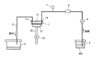
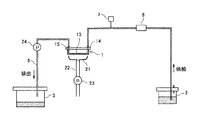
この画像形成装置は、液滴を吐出する循環型の液体吐出ヘッド(以下「ヘッド」という。)1と、ヘッド1に供給する液体であるインク300を収容する液体タンク2と、ヘッド1から排出されるインクを収容する廃液タンク3と、液体タンク2からヘッド1の供給路に至る第1の流路4と、ヘッド1の排出路から廃液タンク4に至る第2の流路5と、液体タンク2からヘッド1に向けてインクを送液する送液手段としての送液ポンプ6を備えている。
Embodiments of the present invention will be described below with reference to the accompanying drawings. First, a first embodiment of the present invention will be described with reference to FIG. 1 and FIG. 1 is a schematic explanatory view of a liquid supply / discharge system in the image forming apparatus according to the embodiment, and FIG. 2 is an explanatory view showing an example of a head according to the embodiment.
The image forming apparatus includes a circulation type liquid discharge head (hereinafter referred to as “head”) 1 that discharges droplets, a
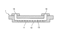
ヘッド1は、例えば図2に示すように、液滴を吐出する複数のノズル11と、各ノズル11が連通する個別流路としての液室12と、各液室12にインクを供給する共通流路としての共通液室13と、共通液室13にインクを供給する供給路(供給口、インク供給ポート)14と、共通液室13からインクを排出する排出路(排出口、インク排出ポート)15などを備えている。
For example, as shown in FIG. 2, the
ここで、ヘッド1の共通液室13の供給路14に接続される第1の流路4は、ヘッド1に対して上方から接続され、第1の流路4には上下方向に配置される上下方向部分(これを「流路部分」という。)4aが生じている。
Here, the first flow path 4 connected to the
そして、第1の流路4内に、第1の流路4の内径以上の径の気泡を混入する気泡混入手段7を備えている。また、第1の流路4には、気泡混入手段7と液体タンク2との間にインクをろ過するフィルタ手段8が設けられている。
A bubble mixing means 7 is provided in the first channel 4 for mixing bubbles having a diameter equal to or larger than the inner diameter of the first channel 4. The first flow path 4 is provided with filter means 8 for filtering ink between the bubble mixing means 7 and the
また、ヘッド1のノズル面をキャッピングするキャップ手段21と、キャップ手段21に排出経路22を介して接続された負圧発生手段としての吸引ポンプ23を備えている。
Further, a
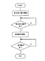
次に、この実施形態における気泡排出動作について図3のフロー図を参照して説明する。
まず、気泡混入手段7によって第1の流路4内に、第1の流路4の内径以上の径の気泡を混入する気泡混入動作を開始し、気泡混入動作完了後、送液ポンプ6を駆動して液体タンク2から送液することで、第1の流路4の内径以上の径の気泡を第1の流路4、ヘッド1の共通液室13、第2の流路5を通じて廃液タンク3に排出させる送液動作を行い、送液動作完了後処理を終了する。
Next, the bubble discharging operation in this embodiment will be described with reference to the flowchart of FIG.
First, the bubble mixing means 7 starts a bubble mixing operation for mixing bubbles having a diameter equal to or larger than the inner diameter of the first channel 4 into the first channel 4, and after the bubble mixing operation is completed, the liquid feed pump 6 is turned on. By driving and feeding liquid from the
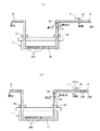
この気泡排出動作について図4の説明図を参照して説明する。
例えば、ヘッド1の共通液室13内及び第1の流路4内に複数の気泡360、361が侵入しているとき、第1の流路4の流路部分4aに存在する気泡361には浮力が作用している。そのため、気泡361を排出するためには送液するインクの流速を高める必要があり、また、気泡360、361が共通液室13や第1の流路4の径に比べて小さいときには、流路内に生じさせるインクの流速が気泡には作用しにくいために、さらに流速を高める必要があり、その結果気泡排出に必要なインク消費量が増大する。
This bubble discharging operation will be described with reference to the explanatory view of FIG.
For example, when a plurality of
そこで、本実施形態では、図4(a)に示すように、気泡混入手段7によって第1の流路4内に、第1の流路4の内径以上の径の気泡(混入気泡)362を混入する。この状態で、液体タンク2からの送液を行うことで、図4(b)に示すように、混入気泡362を廃液タンク3まで送って排出させると、第1の流路4や共通液室13内に含まれていた気泡361、360は、混入気泡362の移動に伴って押し出され、或いは混入気泡362と合体して、第2の流路5を経て廃液タンク3に排出される。
Therefore, in the present embodiment, as shown in FIG. 4A, bubbles (mixed bubbles) 362 having a diameter equal to or larger than the inner diameter of the first channel 4 are formed in the first channel 4 by the
すなわち、侵入している気泡よりも大きな径の気泡を敢えて混入して、混入させた気泡で侵入している気泡を押し出すことができるので、送液するインクの流速を高めることなく、侵入している気泡を排出することができ、気泡排出動作に必要なインク消費量を少なくすることができる。 In other words, it is possible to deliberately mix bubbles with a diameter larger than the invading bubbles, and push out the invading bubbles with the mixed bubbles, so that the intruding without increasing the flow rate of the ink to be fed The discharged air bubbles can be discharged, and the ink consumption necessary for the bubble discharging operation can be reduced.
また、気泡混入手段7と液体タンク2との間にフィルタ手段8を設けることで、混入した気泡362がフィルタ手段8を通過しないため、気泡362が微小化せずに、第1の流路4内の流速を効果的に気泡362に作用させることができる。
Further, by providing the
ここで、具体例について説明すると、第1の流路4の内径がφ3mm、共通液室13の内径が2mm(断面四画形状)の流路の場合、第1の流路4内に混入する流路内径以上の気泡362の径は、φ3mm以上の球体形状であることが好ましく、より好ましくは、第1の流路4の内径径に対して、1.1〜1.2倍の径とする。混入する気泡の径が第1の流路の内径の1.2倍を超えると、混入させた気泡を排出するための液体の流速が大きくなり、1.1倍未満では確実に侵入している気泡を押し出せないおそれがある。
Here, a specific example will be described. In the case where the first flow path 4 has a diameter of φ3 mm and the
また、送液手段による混入気泡362を排出させるときの送液速度(移動速度)は、下方に向いた流路部分4aがある場合には気泡に作用する浮力に対して排出可能な送液速度以上が必要となる。実験では、0.5mm/sec以上の送液速度が必要であったが、この送液速度が遅いと、気泡排出動作が完了するまでの時間が長くなり、またこの送液速度が速いと、気泡排出動作で排出消費される液体量が増大することになる。したがって、この点を考慮した送液速度を設定することが好ましい。
Further, the liquid feeding speed (moving speed) when discharging the
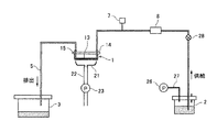
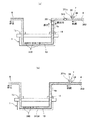
次に、本発明の第2実施形態について図5を参照して説明する。なお、図5は同実施形態に係る画像形成装置における液体供給排出系の模式的説明図である。
ここでは、液体タンク2側から廃液タンク3側にインクを送液する液体送液手段として、第2の経路5内に液体を吸引する吸引手段25を設けている。このような構成でも前記第1実施形態と同様な作用効果を得ることができる。
Next, a second embodiment of the present invention will be described with reference to FIG. FIG. 5 is a schematic explanatory view of a liquid supply / discharge system in the image forming apparatus according to the embodiment.
Here, a suction means 25 for sucking the liquid is provided in the
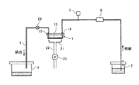
次に、本発明の第3実施形態について図6を参照して説明する。なお、図6は同実施形態に係る画像形成装置における液体供給排出系の模式的説明図である。
ここでは、液体タンク2側から廃液タンク3側にインクを送液する液体送液手段として、液体タンク2内のインクを第3の経路27を介して加圧する加圧手段(加圧ポンプ)26を設け、第1の流路4には開閉弁28を設けている。
Next, a third embodiment of the present invention will be described with reference to FIG. FIG. 6 is a schematic explanatory diagram of a liquid supply / discharge system in the image forming apparatus according to the embodiment.
Here, as a liquid feeding means for feeding ink from the
この送液手段による送液を行うときには、開閉弁28を閉状態にし、液体タンク2を密閉した状態で、加圧手段26により液体タンク2を加圧し、液体タンク2内が閾値の圧力まで到達後、開閉弁28を開状態にすることで、液体タンク2から液体が第1の流路4に送液される。このような構成でも前記第1実施形態と同様な作用効果を得ることができる。
When liquid feeding is performed by the liquid feeding means, the open /
次に、本発明の第4実施形態について図7を参照して説明する。なお、図7は同実施形態に係る画像形成装置における液体供給排出系の模式的説明図である。
ここでは、第2の流路5内に開閉弁29を設け、キャップ部材21でヘッド1のノズル面をキャッピングして吸引手段23を駆動してキャップ部材21内を負圧にすることによって、ヘッド1のノズル11から液体を吸引排出させることにより、液体タンク2から第1の流路4に送液させて気泡混入手段7で混入させた気泡を排出させる。つまり、キャップ部材21及び吸引手段(吸引ポンプ)23で送液手段を構成している。このような構成でも前記第1実施形態と同様な作用効果を得ることができる。
Next, a fourth embodiment of the present invention will be described with reference to FIG. FIG. 7 is a schematic explanatory view of a liquid supply / discharge system in the image forming apparatus according to the embodiment.
Here, an opening / closing
なお、このようにヘッドのノズルから吸引排出を行う構成は、ヘッド1を非循環型ヘッドで構成した場合にも同様に適用することができる。
Note that the structure in which suction and discharge are performed from the nozzles of the head in this way can be similarly applied to the case where the
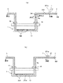
次に、本発明の第5実施形態について図8及び図9を参照して説明する。なお、図8及び図9は同実施形に係る態画像形成装置における液体供給排出系を気泡排出動作とともに説明する模式的説明図である。
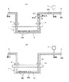
ここでは、気泡混入手段7は、第1の流路4から分岐され、端部が閉じられた分岐部からなる気泡停留部37で構成されている。この気泡停留部37は第1の流路よりも上方向(重力方向と反対方向)に分岐している。
Next, a fifth embodiment of the present invention will be described with reference to FIGS. 8 and 9 are schematic explanatory views for explaining the liquid supply / discharge system together with the bubble discharge operation in the state image forming apparatus according to the embodiment.
Here, the bubble mixing means 7 is composed of a
ここで、図8(a)に示すように、気泡停留部37は第1の流路4に連通しているのでインク(液体)で満たされているが、図8(b)に示すように、第1の流路4内に侵入して流れてくる微小な気泡370が気泡停留部37に到達すると、浮力によって気泡停留部37に停留し、徐々に気泡371bとして溜まって行くことになる。
Here, as shown in FIG. 8A, the
そして、図9(a)に示すように、気泡停留部37内で保持可能な所定量を超える所定の気泡371cになると、気泡停留部37の気泡371cから分離されて第1の流路4の内径以上の気泡372が第1の流路4内に混入する。そして、図9(b)に示すように、混入気泡372dは第1の流路4などの流路を流れるインクの流速により、共通液室13を経て、第2の流路5から廃液タンク3に排出される。
Then, as shown in FIG. 9A, when a predetermined amount of
このとき、流路内を移動する気泡372dは、第1の流路4内の微小な気泡361及び、共通液室332内の微小な気泡360を押し出しながら、あるいはこれらと結合して一体になりながら、第2の流路5に移動して行く。この場合、流路を塞ぐようにして混入した気泡372dは、流路内に生じる液体の流速が効果的に作用するため、流速が作用しにくい微小な気泡360、361を効果的に排出することができる。
At this time, the
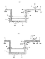
次に、本発明の第6実施形態について図10及び図11を参照して説明する。なお、図10及び図11は同実施形に係る態画像形成装置における液体供給排出系を気泡排出動作とともに説明する模式的説明図である。
ここでは、気泡混入手段7は、第1の流路4から分岐され、端部が閉じられた分岐部からなり、一部が可撓性部材で形成されて内容積を変化できる気泡停留部38で構成され、気泡停留部38を外部から押圧して内容積を減少させる押圧変形させる押圧手段39を備えている。
Next, a sixth embodiment of the present invention will be described with reference to FIGS. 10 and 11 are schematic explanatory views for explaining the liquid supply / discharge system together with the bubble discharge operation in the state image forming apparatus according to the embodiment.
Here, the bubble mixing means 7 is composed of a branch portion branched from the first flow path 4 and closed at the end, and a
ここで、図10(a)に示すように、気泡停留部38は第1の流路4に連通しているのでインク(液体)で満たされているが、図10(b)に示すように、第1の流路4内に侵入して流れてくる微小な気泡370が気泡停留部38に到達すると、浮力によって気泡停留部38に停留し、徐々に気泡371bとして溜まって行くことになる。
Here, as shown in FIG. 10 (a), the
そして、図11(a)に示すように、押圧手段39で気泡停留部38を変形させて内容積を減じることにより、気泡停留部38の気泡371cから分離されて第1の流路4の内径以上の気泡372が第1の流路4内に混入する。そして、図11(b)に示すように、混入気泡372dは第1の流路4などの流路を流れるインクの流速により、共通液室13を経て、第2の流路5から廃液タンク3に排出される。
Then, as shown in FIG. 11A, the inner diameter of the first channel 4 is separated from the
このとき、流路内を移動する気泡372dは、第1の流路4内の微小な気泡361及び、共通液室332内の微小な気泡360を押し出しながら、あるいはこれらと結合して一体になりながら、第2の流路5に移動して行く。この場合、流路を塞ぐようにして混入した気泡372dは、流路内に生じる液体の流速が効果的に作用するため、流速が作用しにくい微小な気泡360、361を効果的に排出することができる。
At this time, the
この実施形態において、第1の流路4への気泡の混入のタイミングは、押圧手段39を駆動することにより、任意のタイミングで実施することができる。
In this embodiment, the timing of mixing bubbles into the first flow path 4 can be performed at an arbitrary timing by driving the
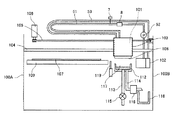
次に、上記各実施形態で説明した液体供給排出系を備える画像形成装置の一例について図12を参照して説明する。
この画像形成装置は、上記液体吐出ヘッドからなる記録ヘッド101を、キャリッジ103に搭載して、左右の側板100A、100B間に横架した主ガイドロッド104と図示しない副ガイド部材とで摺動自在に支持している。この記録ヘッド101は、タイミングベルト105を介して主走査モータ106によって主走査方向に移動走査される。一方、被記録媒体107は記録ヘッド101のノズル面108と対向し、記録ヘッド101の移動方向と直交する方向に搬送ローラ109によって搬送され、記録ヘッド101から画像に応じて吐出されるインク滴が付着されて画像が形成される。
Next, an example of an image forming apparatus including the liquid supply / discharge system described in the above embodiments will be described with reference to FIG.
In this image forming apparatus, a
記録ヘッド101へのインクの供給は、液体タンク2や廃液タンク3等が納められたタンクユニット102からインク供給ポンプ52を経由してフレキシブルなインク供給径路(第1の流路)51によってなされる。また、記録ヘッド101にはノズルから吐出又は排出されなかったインクをインク戻し径路(第2の流路)53を通じてタンクユニット102に戻される。
Ink is supplied to the
また、記録領域外に設けられたキャップ部材111は、複数のノズル11を有するノズル面108キャッピングする弾性体、好ましくはシリコンゴム等からなる。非記録時には、記録ヘッド101がキャップ部材111の上方まで移動し、キャップ部材111が図示していないキャップ移動機構によって移動してノズル面108をキャッピングする。このキャップ部材111内には、インク吸引の際の吸引容易化、キャップ内雰囲気湿潤化等のため、インク吸収シート112が設けられている。
The cap member 111 provided outside the recording area is made of an elastic body, preferably silicon rubber, for capping the
このキャップ部材111には、底面に2本のチューブ113、114が連結され、チューブ113は大気開放弁115を介して大気に連通される。チューブ114は吸引ポンプ116に接続され、キャップ部材111でノズル面108をキャッピングし、大気開放弁115を閉じた状態で、吸引ポンプ116を駆動してキャップ部材111内に負圧を発生させることで、記録ヘッド101のノズルからインクを吸引し、大気開放弁115を開放することでキャップ部材111内の空間117に溜まったインクを廃液タンク118に排出する。また、キャップ部材111は、大気開放弁115を閉じた状態でノズル面108に接触させ保持することで、記録ヘッド101のノズルの乾燥を防止する。
Two
さらに、図示していないワイパ移動機構によってワイパーブレード(ワイパ部材)119を記録ヘッド101のノズル面108に接触する高さまで移動させ、記録ヘッド101を主走査方向に移動させてワイパーブレード119によりノズル面108に付着したインクや塵埃を払拭し、ノズル11内のメニスカスの生成やノズル面108のクリーニングを行うことができる。
Further, a wiper blade (wiper member) 119 is moved to a height at which it contacts the
なお、上記実施形態においては、本発明をシリアル型画像形成装置に適用した例で説明しているが、ライン型画像形成装置にも同様に適用できる。 In the above-described embodiment, an example in which the present invention is applied to a serial type image forming apparatus has been described. However, the present invention can be similarly applied to a line type image forming apparatus.
1 ヘッド
2 液体タンク
3 廃液タンク
4 第1の流路
5 第2の流路
7 気泡混入手段
8 フィルタ手段
13 共通流路
37、38 気泡停留部
39 押圧手段
DESCRIPTION OF
Claims (6)
前記ヘッドに供給する液体を収容する液体タンクと、
前記ヘッドから排出される液体を収容する廃液タンクと、
前記液体タンクから前記ヘッドに至る第1の流路と、
前記ヘッドから前記廃液タンクに至る第2の流路と、
前記第1の流路内に、前記第1の流路の内径以上の径の気泡を混入する気泡混入手段と、
前記液体タンクから前記ヘッドに前記液体を送液する送液手段と、を備え、
前記気泡混入手段で前記第1の流路内に前記第1の流路の内径以上の径の気泡を混入させた状態で、前記送液手段によって前記液体を送液して前記混入された気泡を排出させる
ことを特徴とする画像形成装置。 A head for discharging droplets;
A liquid tank for storing liquid to be supplied to the head;
A waste liquid tank for storing liquid discharged from the head;
A first flow path from the liquid tank to the head;
A second flow path from the head to the waste liquid tank;
Bubble mixing means for mixing bubbles having a diameter equal to or larger than the inner diameter of the first channel in the first channel;
Liquid feeding means for feeding the liquid from the liquid tank to the head, and
In the state in which bubbles having a diameter equal to or larger than the inner diameter of the first flow path are mixed in the first flow path by the bubble mixing means, the liquid is fed by the liquid feeding means and the mixed bubbles. An image forming apparatus that discharges the water.
前記ヘッドに供給する液体を収容する液体タンクと、
前記液体タンクから前記ヘッドに至る第1の流路と、
前記第1の流路内に、前記第1の流路の内径以上の径の気泡を混入する気泡混入手段と、
前記液体タンクから前記ヘッドに前記液体を送液する送液手段と、を備え、
前記気泡混入手段で前記第1の流路内に前記第1の流路の内径以上の径の気泡を混入させた状態で、前記送液手段によって前記液体を送液して前記混入された気泡を排出させる
ことを特徴とする画像形成装置。 A head for discharging droplets;
A liquid tank for storing liquid to be supplied to the head;
A first flow path from the liquid tank to the head;
Bubble mixing means for mixing bubbles having a diameter equal to or larger than the inner diameter of the first channel in the first channel;
Liquid feeding means for feeding the liquid from the liquid tank to the head, and
In the state in which bubbles having a diameter equal to or larger than the inner diameter of the first flow path are mixed in the first flow path by the bubble mixing means, the liquid is fed by the liquid feeding means and the mixed bubbles. An image forming apparatus that discharges the water.
Priority Applications (1)
| Application Number | Priority Date | Filing Date | Title |
|---|---|---|---|
| JP2010162640A JP2012024934A (en) | 2010-07-20 | 2010-07-20 | Image forming apparatus |
Applications Claiming Priority (1)
| Application Number | Priority Date | Filing Date | Title |
|---|---|---|---|
| JP2010162640A JP2012024934A (en) | 2010-07-20 | 2010-07-20 | Image forming apparatus |
Publications (1)
| Publication Number | Publication Date |
|---|---|
| JP2012024934A true JP2012024934A (en) | 2012-02-09 |
Family
ID=45778486
Family Applications (1)
| Application Number | Title | Priority Date | Filing Date |
|---|---|---|---|
| JP2010162640A Pending JP2012024934A (en) | 2010-07-20 | 2010-07-20 | Image forming apparatus |
Country Status (1)
| Country | Link |
|---|---|
| JP (1) | JP2012024934A (en) |
Cited By (2)
| Publication number | Priority date | Publication date | Assignee | Title |
|---|---|---|---|---|
| US9573381B2 (en) | 2013-11-22 | 2017-02-21 | Canon Kabushiki Kaisha | Printing apparatus and bubble exhaust method therefor |
| WO2018225333A1 (en) * | 2017-06-06 | 2018-12-13 | コニカミノルタ株式会社 | Ink jet head and ink jet recording apparatus |
Citations (6)
| Publication number | Priority date | Publication date | Assignee | Title |
|---|---|---|---|---|
| JP2000103075A (en) * | 1998-09-29 | 2000-04-11 | Brother Ind Ltd | Ink jet recording device |
| JP2007030202A (en) * | 2005-07-22 | 2007-02-08 | Fuji Xerox Co Ltd | Liquid drop ejector and method for filling liquid |
| JP2007069419A (en) * | 2005-09-06 | 2007-03-22 | Fuji Xerox Co Ltd | Liquid droplet discharge head |
| JP2008183746A (en) * | 2007-01-29 | 2008-08-14 | Ricoh Co Ltd | Liquid supply apparatus and image forming apparatus |
| JP2009066781A (en) * | 2007-09-10 | 2009-04-02 | Konica Minolta Ij Technologies Inc | Print head unit and inkjet printer |
| JP2009160807A (en) * | 2008-01-04 | 2009-07-23 | Olympus Corp | Ink circulation confirmation method and ink filling method |
-
2010
- 2010-07-20 JP JP2010162640A patent/JP2012024934A/en active Pending
Patent Citations (6)
| Publication number | Priority date | Publication date | Assignee | Title |
|---|---|---|---|---|
| JP2000103075A (en) * | 1998-09-29 | 2000-04-11 | Brother Ind Ltd | Ink jet recording device |
| JP2007030202A (en) * | 2005-07-22 | 2007-02-08 | Fuji Xerox Co Ltd | Liquid drop ejector and method for filling liquid |
| JP2007069419A (en) * | 2005-09-06 | 2007-03-22 | Fuji Xerox Co Ltd | Liquid droplet discharge head |
| JP2008183746A (en) * | 2007-01-29 | 2008-08-14 | Ricoh Co Ltd | Liquid supply apparatus and image forming apparatus |
| JP2009066781A (en) * | 2007-09-10 | 2009-04-02 | Konica Minolta Ij Technologies Inc | Print head unit and inkjet printer |
| JP2009160807A (en) * | 2008-01-04 | 2009-07-23 | Olympus Corp | Ink circulation confirmation method and ink filling method |
Cited By (4)
| Publication number | Priority date | Publication date | Assignee | Title |
|---|---|---|---|---|
| US9573381B2 (en) | 2013-11-22 | 2017-02-21 | Canon Kabushiki Kaisha | Printing apparatus and bubble exhaust method therefor |
| WO2018225333A1 (en) * | 2017-06-06 | 2018-12-13 | コニカミノルタ株式会社 | Ink jet head and ink jet recording apparatus |
| JPWO2018225333A1 (en) * | 2017-06-06 | 2020-04-09 | コニカミノルタ株式会社 | Ink jet head and ink jet recording apparatus |
| JP7036113B2 (en) | 2017-06-06 | 2022-03-15 | コニカミノルタ株式会社 | Inkjet head and inkjet recording device |
Similar Documents
| Publication | Publication Date | Title |
|---|---|---|
| CN101835616B (en) | Discharging device and printing apparatus | |
| JP5211931B2 (en) | Fluid ejection device | |
| US8480213B2 (en) | Liquid containing tank, liquid-jet head unit, and image forming apparatus | |
| US9498958B2 (en) | Liquid jetting apparatus | |
| JP2011235470A (en) | Image forming apparatus and liquid filling method in the same | |
| JP2009269313A (en) | Ink-jet recording device and pre-ejection method | |
| JP5954564B2 (en) | Apparatus including liquid cleaning and filling unit, liquid cleaning and filling method in image forming apparatus, and apparatus including liquid cleaning and filling kit | |
| JP5995184B2 (en) | Image forming apparatus | |
| JP2012096510A (en) | Fluid storage tank, fluid ejecting head unit and image forming apparatus | |
| JP5304548B2 (en) | Liquid ejection device | |
| JP2012006374A (en) | Liquid filling unit, image forming apparatus, liquid filling method in image forming apparatus, liquid filling kit | |
| US20180194138A1 (en) | Liquid ejecting apparatus | |
| JP6127469B2 (en) | Liquid ejection device | |
| JP2012024934A (en) | Image forming apparatus | |
| JP2002086762A (en) | Ink jet recording device | |
| US8567902B2 (en) | Waste liquid recovery apparatus and liquid ejecting apparatus | |
| JP2006035786A (en) | Inkjet recording device | |
| JP5510820B2 (en) | Liquid discharge head unit and image forming apparatus | |
| JP2018083342A (en) | Inkjet printer | |
| JP2010105310A (en) | Liquid jet device | |
| JP2012035432A (en) | Image forming apparatus | |
| JP2007118344A (en) | Liquid jet device | |
| JP5730486B2 (en) | Head cleaning device, head cleaning method, and ink jet printer | |
| JP5310093B2 (en) | Fluid ejection device | |
| JP6331473B2 (en) | Liquid receiving apparatus, liquid ejecting apparatus, and liquid discharging method |
Legal Events
| Date | Code | Title | Description |
|---|---|---|---|
| A621 | Written request for application examination |
Free format text: JAPANESE INTERMEDIATE CODE: A621 Effective date: 20130523 |
|
| A977 | Report on retrieval |
Free format text: JAPANESE INTERMEDIATE CODE: A971007 Effective date: 20140116 |
|
| A131 | Notification of reasons for refusal |
Free format text: JAPANESE INTERMEDIATE CODE: A131 Effective date: 20140128 |
|
| A521 | Written amendment |
Free format text: JAPANESE INTERMEDIATE CODE: A523 Effective date: 20140326 |
|
| A131 | Notification of reasons for refusal |
Free format text: JAPANESE INTERMEDIATE CODE: A131 Effective date: 20141111 |
|
| A02 | Decision of refusal |
Free format text: JAPANESE INTERMEDIATE CODE: A02 Effective date: 20150310 |