JP2012024925A - Rotating cutting insert assembly, and method of using the same - Google Patents
Rotating cutting insert assembly, and method of using the same Download PDFInfo
- Publication number
- JP2012024925A JP2012024925A JP2011243423A JP2011243423A JP2012024925A JP 2012024925 A JP2012024925 A JP 2012024925A JP 2011243423 A JP2011243423 A JP 2011243423A JP 2011243423 A JP2011243423 A JP 2011243423A JP 2012024925 A JP2012024925 A JP 2012024925A
- Authority
- JP
- Japan
- Prior art keywords
- cutting insert
- tool holder
- cutting
- workpiece
- top surface
- Prior art date
- Legal status (The legal status is an assumption and is not a legal conclusion. Google has not performed a legal analysis and makes no representation as to the accuracy of the status listed.)
- Pending
Links
- 238000005520 cutting process Methods 0.000 title claims abstract description 252
- 238000000034 method Methods 0.000 title claims abstract description 11
- 239000012530 fluid Substances 0.000 claims description 11
- 238000003754 machining Methods 0.000 claims description 7
- 230000017525 heat dissipation Effects 0.000 claims description 2
- 230000002708 enhancing effect Effects 0.000 abstract 1
- 239000000314 lubricant Substances 0.000 description 12
- 230000007246 mechanism Effects 0.000 description 11
- 239000000463 material Substances 0.000 description 10
- 238000005555 metalworking Methods 0.000 description 9
- 230000001050 lubricating effect Effects 0.000 description 8
- 238000013461 design Methods 0.000 description 4
- 238000005516 engineering process Methods 0.000 description 4
- 230000008901 benefit Effects 0.000 description 3
- 230000008859 change Effects 0.000 description 3
- 238000013459 approach Methods 0.000 description 2
- 238000001816 cooling Methods 0.000 description 2
- 238000010586 diagram Methods 0.000 description 2
- 229910003460 diamond Inorganic materials 0.000 description 2
- 239000010432 diamond Substances 0.000 description 2
- 238000009826 distribution Methods 0.000 description 2
- 239000002184 metal Substances 0.000 description 2
- 238000003801 milling Methods 0.000 description 2
- 229910000851 Alloy steel Inorganic materials 0.000 description 1
- 229910052582 BN Inorganic materials 0.000 description 1
- PZNSFCLAULLKQX-UHFFFAOYSA-N Boron nitride Chemical compound N#B PZNSFCLAULLKQX-UHFFFAOYSA-N 0.000 description 1
- 229910000975 Carbon steel Inorganic materials 0.000 description 1
- 229910000831 Steel Inorganic materials 0.000 description 1
- 238000002679 ablation Methods 0.000 description 1
- 230000004308 accommodation Effects 0.000 description 1
- 239000010962 carbon steel Substances 0.000 description 1
- -1 cemented carbide Substances 0.000 description 1
- 239000000919 ceramic Substances 0.000 description 1
- 239000011195 cermet Substances 0.000 description 1
- 239000011248 coating agent Substances 0.000 description 1
- 238000000576 coating method Methods 0.000 description 1
- 238000004891 communication Methods 0.000 description 1
- 230000005484 gravity Effects 0.000 description 1
- 239000003779 heat-resistant material Substances 0.000 description 1
- 229910001026 inconel Inorganic materials 0.000 description 1
- 230000003993 interaction Effects 0.000 description 1
- 230000007257 malfunction Effects 0.000 description 1
- 238000013021 overheating Methods 0.000 description 1
- 230000002093 peripheral effect Effects 0.000 description 1
- 230000002441 reversible effect Effects 0.000 description 1
- 230000007480 spreading Effects 0.000 description 1
- 238000003892 spreading Methods 0.000 description 1
- 239000010959 steel Substances 0.000 description 1
- 238000006467 substitution reaction Methods 0.000 description 1
- 230000001360 synchronised effect Effects 0.000 description 1
- 239000002699 waste material Substances 0.000 description 1
Images

Classifications
-
- B—PERFORMING OPERATIONS; TRANSPORTING
- B23—MACHINE TOOLS; METAL-WORKING NOT OTHERWISE PROVIDED FOR
- B23B—TURNING; BORING
- B23B31/00—Chucks; Expansion mandrels; Adaptations thereof for remote control
- B23B31/40—Expansion mandrels
- B23B31/4006—Gripping the work or tool by a split sleeve
-
- B—PERFORMING OPERATIONS; TRANSPORTING
- B23—MACHINE TOOLS; METAL-WORKING NOT OTHERWISE PROVIDED FOR
- B23B—TURNING; BORING
- B23B1/00—Methods for turning or working essentially requiring the use of turning-machines; Use of auxiliary equipment in connection with such methods
-
- B—PERFORMING OPERATIONS; TRANSPORTING
- B23—MACHINE TOOLS; METAL-WORKING NOT OTHERWISE PROVIDED FOR
- B23B—TURNING; BORING
- B23B27/00—Tools for turning or boring machines; Tools of a similar kind in general; Accessories therefor
- B23B27/10—Cutting tools with special provision for cooling
-
- B—PERFORMING OPERATIONS; TRANSPORTING
- B23—MACHINE TOOLS; METAL-WORKING NOT OTHERWISE PROVIDED FOR
- B23B—TURNING; BORING
- B23B27/00—Tools for turning or boring machines; Tools of a similar kind in general; Accessories therefor
- B23B27/10—Cutting tools with special provision for cooling
- B23B27/12—Cutting tools with special provision for cooling with a continuously-rotated circular cutting edge; Holders therefor
-
- B—PERFORMING OPERATIONS; TRANSPORTING
- B23—MACHINE TOOLS; METAL-WORKING NOT OTHERWISE PROVIDED FOR
- B23B—TURNING; BORING
- B23B27/00—Tools for turning or boring machines; Tools of a similar kind in general; Accessories therefor
- B23B27/14—Cutting tools of which the bits or tips or cutting inserts are of special material
- B23B27/16—Cutting tools of which the bits or tips or cutting inserts are of special material with exchangeable cutting bits or cutting inserts, e.g. able to be clamped
- B23B27/1603—Cutting tools of which the bits or tips or cutting inserts are of special material with exchangeable cutting bits or cutting inserts, e.g. able to be clamped with specially shaped plate-like exchangeable cutting inserts, e.g. chip-breaking groove
-
- B—PERFORMING OPERATIONS; TRANSPORTING
- B23—MACHINE TOOLS; METAL-WORKING NOT OTHERWISE PROVIDED FOR
- B23G—THREAD CUTTING; WORKING OF SCREWS, BOLT HEADS, OR NUTS, IN CONJUNCTION THEREWITH
- B23G1/00—Thread cutting; Automatic machines specially designed therefor
- B23G1/02—Thread cutting; Automatic machines specially designed therefor on an external or internal cylindrical or conical surface, e.g. on recesses
-
- B—PERFORMING OPERATIONS; TRANSPORTING
- B23—MACHINE TOOLS; METAL-WORKING NOT OTHERWISE PROVIDED FOR
- B23Q—DETAILS, COMPONENTS, OR ACCESSORIES FOR MACHINE TOOLS, e.g. ARRANGEMENTS FOR COPYING OR CONTROLLING; MACHINE TOOLS IN GENERAL CHARACTERISED BY THE CONSTRUCTION OF PARTICULAR DETAILS OR COMPONENTS; COMBINATIONS OR ASSOCIATIONS OF METAL-WORKING MACHINES, NOT DIRECTED TO A PARTICULAR RESULT
- B23Q11/00—Accessories fitted to machine tools for keeping tools or parts of the machine in good working condition or for cooling work; Safety devices specially combined with or arranged in, or specially adapted for use in connection with, machine tools
- B23Q11/10—Arrangements for cooling or lubricating tools or work
-
- B—PERFORMING OPERATIONS; TRANSPORTING
- B23—MACHINE TOOLS; METAL-WORKING NOT OTHERWISE PROVIDED FOR
- B23B—TURNING; BORING
- B23B2200/00—Details of cutting inserts
- B23B2200/04—Overall shape
- B23B2200/0438—Octagonal
-
- B—PERFORMING OPERATIONS; TRANSPORTING
- B23—MACHINE TOOLS; METAL-WORKING NOT OTHERWISE PROVIDED FOR
- B23B—TURNING; BORING
- B23B2200/00—Details of cutting inserts
- B23B2200/04—Overall shape
- B23B2200/0461—Round
-
- B—PERFORMING OPERATIONS; TRANSPORTING
- B23—MACHINE TOOLS; METAL-WORKING NOT OTHERWISE PROVIDED FOR
- B23B—TURNING; BORING
- B23B2200/00—Details of cutting inserts
- B23B2200/08—Rake or top surfaces
- B23B2200/081—Rake or top surfaces with projections
-
- B—PERFORMING OPERATIONS; TRANSPORTING
- B23—MACHINE TOOLS; METAL-WORKING NOT OTHERWISE PROVIDED FOR
- B23B—TURNING; BORING
- B23B2200/00—Details of cutting inserts
- B23B2200/16—Supporting or bottom surfaces
- B23B2200/161—Supporting or bottom surfaces with projections
-
- B—PERFORMING OPERATIONS; TRANSPORTING
- B23—MACHINE TOOLS; METAL-WORKING NOT OTHERWISE PROVIDED FOR
- B23B—TURNING; BORING
- B23B2200/00—Details of cutting inserts
- B23B2200/20—Top or side views of the cutting edge
- B23B2200/204—Top or side views of the cutting edge with discontinuous cutting edge
-
- B—PERFORMING OPERATIONS; TRANSPORTING
- B23—MACHINE TOOLS; METAL-WORKING NOT OTHERWISE PROVIDED FOR
- B23B—TURNING; BORING
- B23B2260/00—Details of constructional elements
- B23B2260/042—Collets of known configuration, i.e. devices using a collet
-
- B—PERFORMING OPERATIONS; TRANSPORTING
- B23—MACHINE TOOLS; METAL-WORKING NOT OTHERWISE PROVIDED FOR
- B23B—TURNING; BORING
- B23B2265/00—Details of general geometric configurations
- B23B2265/16—Elliptical
-
- Y—GENERAL TAGGING OF NEW TECHNOLOGICAL DEVELOPMENTS; GENERAL TAGGING OF CROSS-SECTIONAL TECHNOLOGIES SPANNING OVER SEVERAL SECTIONS OF THE IPC; TECHNICAL SUBJECTS COVERED BY FORMER USPC CROSS-REFERENCE ART COLLECTIONS [XRACs] AND DIGESTS
- Y10—TECHNICAL SUBJECTS COVERED BY FORMER USPC
- Y10T—TECHNICAL SUBJECTS COVERED BY FORMER US CLASSIFICATION
- Y10T279/00—Chucks or sockets
- Y10T279/16—Longitudinal screw clamp
-
- Y—GENERAL TAGGING OF NEW TECHNOLOGICAL DEVELOPMENTS; GENERAL TAGGING OF CROSS-SECTIONAL TECHNOLOGIES SPANNING OVER SEVERAL SECTIONS OF THE IPC; TECHNICAL SUBJECTS COVERED BY FORMER USPC CROSS-REFERENCE ART COLLECTIONS [XRACs] AND DIGESTS
- Y10—TECHNICAL SUBJECTS COVERED BY FORMER USPC
- Y10T—TECHNICAL SUBJECTS COVERED BY FORMER US CLASSIFICATION
- Y10T407/00—Cutters, for shaping
- Y10T407/14—Cutters, for shaping with means to apply fluid to cutting tool
-
- Y—GENERAL TAGGING OF NEW TECHNOLOGICAL DEVELOPMENTS; GENERAL TAGGING OF CROSS-SECTIONAL TECHNOLOGIES SPANNING OVER SEVERAL SECTIONS OF THE IPC; TECHNICAL SUBJECTS COVERED BY FORMER USPC CROSS-REFERENCE ART COLLECTIONS [XRACs] AND DIGESTS
- Y10—TECHNICAL SUBJECTS COVERED BY FORMER USPC
- Y10T—TECHNICAL SUBJECTS COVERED BY FORMER US CLASSIFICATION
- Y10T407/00—Cutters, for shaping
- Y10T407/19—Rotary cutting tool
- Y10T407/1906—Rotary cutting tool including holder [i.e., head] having seat for inserted tool
- Y10T407/1934—Rotary cutting tool including holder [i.e., head] having seat for inserted tool with separate means to fasten tool to holder
- Y10T407/1938—Wedge clamp element
- Y10T407/194—Resilient clamp jaw
-
- Y—GENERAL TAGGING OF NEW TECHNOLOGICAL DEVELOPMENTS; GENERAL TAGGING OF CROSS-SECTIONAL TECHNOLOGIES SPANNING OVER SEVERAL SECTIONS OF THE IPC; TECHNICAL SUBJECTS COVERED BY FORMER USPC CROSS-REFERENCE ART COLLECTIONS [XRACs] AND DIGESTS
- Y10—TECHNICAL SUBJECTS COVERED BY FORMER USPC
- Y10T—TECHNICAL SUBJECTS COVERED BY FORMER US CLASSIFICATION
- Y10T407/00—Cutters, for shaping
- Y10T407/22—Cutters, for shaping including holder having seat for inserted tool
- Y10T407/2272—Cutters, for shaping including holder having seat for inserted tool with separate means to fasten tool to holder
- Y10T407/2282—Cutters, for shaping including holder having seat for inserted tool with separate means to fasten tool to holder including tool holding clamp and clamp actuator
- Y10T407/2286—Resiliently biased clamp jaw
-
- Y—GENERAL TAGGING OF NEW TECHNOLOGICAL DEVELOPMENTS; GENERAL TAGGING OF CROSS-SECTIONAL TECHNOLOGIES SPANNING OVER SEVERAL SECTIONS OF THE IPC; TECHNICAL SUBJECTS COVERED BY FORMER USPC CROSS-REFERENCE ART COLLECTIONS [XRACs] AND DIGESTS
- Y10—TECHNICAL SUBJECTS COVERED BY FORMER USPC
- Y10T—TECHNICAL SUBJECTS COVERED BY FORMER US CLASSIFICATION
- Y10T407/00—Cutters, for shaping
- Y10T407/23—Cutters, for shaping including tool having plural alternatively usable cutting edges
- Y10T407/235—Cutters, for shaping including tool having plural alternatively usable cutting edges with integral chip breaker, guide or deflector
-
- Y—GENERAL TAGGING OF NEW TECHNOLOGICAL DEVELOPMENTS; GENERAL TAGGING OF CROSS-SECTIONAL TECHNOLOGIES SPANNING OVER SEVERAL SECTIONS OF THE IPC; TECHNICAL SUBJECTS COVERED BY FORMER USPC CROSS-REFERENCE ART COLLECTIONS [XRACs] AND DIGESTS
- Y10—TECHNICAL SUBJECTS COVERED BY FORMER USPC
- Y10T—TECHNICAL SUBJECTS COVERED BY FORMER US CLASSIFICATION
- Y10T409/00—Gear cutting, milling, or planing
- Y10T409/30—Milling
- Y10T409/303752—Process
- Y10T409/303808—Process including infeeding
-
- Y—GENERAL TAGGING OF NEW TECHNOLOGICAL DEVELOPMENTS; GENERAL TAGGING OF CROSS-SECTIONAL TECHNOLOGIES SPANNING OVER SEVERAL SECTIONS OF THE IPC; TECHNICAL SUBJECTS COVERED BY FORMER USPC CROSS-REFERENCE ART COLLECTIONS [XRACs] AND DIGESTS
- Y10—TECHNICAL SUBJECTS COVERED BY FORMER USPC
- Y10T—TECHNICAL SUBJECTS COVERED BY FORMER US CLASSIFICATION
- Y10T409/00—Gear cutting, milling, or planing
- Y10T409/30—Milling
- Y10T409/303976—Milling with means to control temperature or lubricate
-
- Y—GENERAL TAGGING OF NEW TECHNOLOGICAL DEVELOPMENTS; GENERAL TAGGING OF CROSS-SECTIONAL TECHNOLOGIES SPANNING OVER SEVERAL SECTIONS OF THE IPC; TECHNICAL SUBJECTS COVERED BY FORMER USPC CROSS-REFERENCE ART COLLECTIONS [XRACs] AND DIGESTS
- Y10—TECHNICAL SUBJECTS COVERED BY FORMER USPC
- Y10T—TECHNICAL SUBJECTS COVERED BY FORMER US CLASSIFICATION
- Y10T409/00—Gear cutting, milling, or planing
- Y10T409/30—Milling
- Y10T409/304536—Milling including means to infeed work to cutter
- Y10T409/305544—Milling including means to infeed work to cutter with work holder
- Y10T409/305656—Milling including means to infeed work to cutter with work holder including means to support work for rotation during operation
-
- Y—GENERAL TAGGING OF NEW TECHNOLOGICAL DEVELOPMENTS; GENERAL TAGGING OF CROSS-SECTIONAL TECHNOLOGIES SPANNING OVER SEVERAL SECTIONS OF THE IPC; TECHNICAL SUBJECTS COVERED BY FORMER USPC CROSS-REFERENCE ART COLLECTIONS [XRACs] AND DIGESTS
- Y10—TECHNICAL SUBJECTS COVERED BY FORMER USPC
- Y10T—TECHNICAL SUBJECTS COVERED BY FORMER US CLASSIFICATION
- Y10T409/00—Gear cutting, milling, or planing
- Y10T409/30—Milling
- Y10T409/309352—Cutter spindle or spindle support
- Y10T409/309408—Cutter spindle or spindle support with cutter holder
-
- Y—GENERAL TAGGING OF NEW TECHNOLOGICAL DEVELOPMENTS; GENERAL TAGGING OF CROSS-SECTIONAL TECHNOLOGIES SPANNING OVER SEVERAL SECTIONS OF THE IPC; TECHNICAL SUBJECTS COVERED BY FORMER USPC CROSS-REFERENCE ART COLLECTIONS [XRACs] AND DIGESTS
- Y10—TECHNICAL SUBJECTS COVERED BY FORMER USPC
- Y10T—TECHNICAL SUBJECTS COVERED BY FORMER US CLASSIFICATION
- Y10T82/00—Turning
- Y10T82/10—Process of turning
-
- Y—GENERAL TAGGING OF NEW TECHNOLOGICAL DEVELOPMENTS; GENERAL TAGGING OF CROSS-SECTIONAL TECHNOLOGIES SPANNING OVER SEVERAL SECTIONS OF THE IPC; TECHNICAL SUBJECTS COVERED BY FORMER USPC CROSS-REFERENCE ART COLLECTIONS [XRACs] AND DIGESTS
- Y10—TECHNICAL SUBJECTS COVERED BY FORMER USPC
- Y10T—TECHNICAL SUBJECTS COVERED BY FORMER US CLASSIFICATION
- Y10T82/00—Turning
- Y10T82/25—Lathe
- Y10T82/2529—Revolvable cutter heads
Landscapes
- Engineering & Computer Science (AREA)
- Mechanical Engineering (AREA)
- Milling Processes (AREA)
- Cutting Tools, Boring Holders, And Turrets (AREA)
- Turning (AREA)
Abstract
Description
本発明は、金属加工作業に関し、より詳細には、金属加工作業中に切削用インサートをその中心軸を中心に回転させる方法及びアセンブリに関する。また、本発明は、切削用インサート自体、ツールホルダ及び前記インサートを備えたアセンブリ、並びに、前記アセンブリの動作にも関する。 The present invention relates to metalworking operations and, more particularly, to a method and assembly for rotating a cutting insert about its central axis during metalworking operations. The invention also relates to the cutting insert itself, a tool holder and an assembly comprising the insert, and the operation of the assembly.
保持された切削用インサートが回転する工作物に対して付勢される旋盤作業のような金属加工作業中において、工作物に作用するインサートの切削刃は、作業が完了するまで、又は、切削刃が故障メカニズム(例えば、クレータ摩耗や塑性変形)によって正常に作動しなくなり始めるまで、工作物によって加熱される。このような故障モードを回避すると共に、切削用インサートの動作をより効率的にするため、これまでは、円形の切削用インサートが、その中心軸を中心に自由に回転することができるように、ツールホルダに取り付けられてきた。次に、この切削用インサートは、工作物に向けられ、例えば旋盤上にあるこの工作物の回転運動が切削用インサートに対してその接線方向に作用する力を付与するように方向付けられた。工作物の動きが切削用インサートに対して作用することによって、工作物が機械加工されるだけでなく、さらに、円形の切削用インサートがその切削刃の新しい部分を次々と用いるように回転された。従って、理想的な条件下では、切削刃のいずれの部分も、工作物に対し長時間にわたって露呈されることがなかった。さらに、より低い温度において切削刃を作動させることによって、切削力を高め、機械加工作業の効率を向上させることができた。 During metalworking operations such as lathe work where the held cutting insert is biased against the rotating workpiece, the cutting blade of the insert acting on the workpiece is either until the operation is complete or the cutting blade Is heated by the workpiece until it begins to malfunction due to a failure mechanism (eg, crater wear or plastic deformation). In order to avoid such failure modes and to make the cutting insert more efficient, so far, so that the circular cutting insert can freely rotate about its central axis, Has been attached to the tool holder. The cutting insert was then directed to the workpiece, for example oriented so that the rotational movement of the workpiece on a lathe imparts a force acting on the cutting insert in its tangential direction. As the workpiece movement acts on the cutting insert, not only the workpiece is machined, but also the circular cutting insert is rotated to use new parts of the cutting blade one after another. . Therefore, under ideal conditions, no part of the cutting blade was exposed to the workpiece for a long time. Furthermore, by operating the cutting blade at a lower temperature, it was possible to increase the cutting force and improve the efficiency of machining operations.
このようなタイプの回転インサートは、驚くべき速度と著しく長い工具寿命を呈し得る。しかしながら、この同じ回転インサートは、切削条件がわずかに変わると、或いは、この切削用インサートが回転するのに用いられるカートリッジ軸受部が劣化し始めると、同じぐらい著しく故障し得る。 Such types of rotating inserts can exhibit surprising speed and significantly longer tool life. However, this same rotating insert can fail as severely as the cutting conditions change slightly or if the cartridge bearing used to rotate the cutting insert begins to deteriorate.
米国特許第4,178,818号には、円形の切削端を有する回転切削工具によって回転体を切削する方法が述べられている。この切削用インサートは、ハウジング内部に軸受部によって取り付けられたスピンドルに保持されている。このスピンドルを介して風力タービンに潤滑剤が導入されることによって、切削用インサートが回転される。しかしながら、このような切削用インサートの回転を付勢する潤滑剤の流れによって生じるトルクよりも、切削用インサートを回転させ得る切削力から生じるトルクの方がはるかに大きい。切削用インサートは、主に工作物との相互作用によって回転される。風力タービンは、切削用インサートと工作物とが接触せず摩擦回転しない切削中断中であっても、この円形の切削用インサートが回転を続けられるようにするためのものである。従って、この切削用インサートの設計では、回転する工作物から接線方向の力を引き出すことによって、切削用インサートを回転させている。 U.S. Pat. No. 4,178,818 describes a method of cutting a rotating body with a rotary cutting tool having a circular cutting edge. The cutting insert is held by a spindle that is attached to the inside of the housing by a bearing portion. The lubricant is introduced into the wind turbine via the spindle, whereby the cutting insert is rotated. However, the torque generated by the cutting force capable of rotating the cutting insert is much larger than the torque generated by the flow of the lubricant that urges the rotation of the cutting insert. The cutting insert is rotated mainly by interaction with the workpiece. The wind turbine is intended to allow the circular cutting insert to continue to rotate even during cutting interruptions where the cutting insert and workpiece do not contact and do not rotate frictionally. Thus, in this cutting insert design, the cutting insert is rotated by extracting a tangential force from the rotating workpiece.
金属加工作業中に切削用インサートをその軸を中心に回転させることのできる方法及びアセンブリが必要とされている。このような方法及びアセンブリでは、切削用インサートの回転速度及び回転方向は、工作物の回転によって決定されるのではなく、この切削用インサートに作用する独立した力によって決定される。 What is needed is a method and assembly that can rotate a cutting insert about its axis during metalworking operations. In such a method and assembly, the rotational speed and direction of the cutting insert is not determined by the rotation of the workpiece, but by an independent force acting on the cutting insert.
本発明の一実施形態は、内部を通って延びる中心軸を有する切削用インサートを含むアセンブリに関し、この切削用インサートは、頂面と、底面と、該頂面と該底面との間にある少なくとも1つの側部と、該少なくとも1つの側部と前記頂面との交差部にある切削刃とを有する本体から成る。また、このアセンブリは、前記切削用インサートが取り付けられたツールホルダも含み、このツールホルダは、前記切削用インサートを前記中心軸を中心に所定の回転速度で回転させるように構成されている。 One embodiment of the present invention relates to an assembly including a cutting insert having a central axis extending therethrough, the cutting insert being at least between a top surface, a bottom surface, and the top surface and the bottom surface. It comprises a body having one side and a cutting blade at the intersection of the at least one side and the top surface. The assembly also includes a tool holder to which the cutting insert is attached, and the tool holder is configured to rotate the cutting insert about the central axis at a predetermined rotational speed.
本発明の別の実施形態は、頂面と、底面と、該頂面と該底面との間にある少なくとも1つの側部と、該少なくとも1つの側部と前記頂面との交差部にある切削刃と、前記頂面及び前記底面を通って延びる中心軸とを備えた本体を有する切削用インサートを用いる方法であって、前記中心軸と回転する工作物の長手方向軸とが角度を成すように前記切削用インサートを位置合わせするステップと、前記切削用インサートを前記切削用インサートの前記中心軸を中心に回転させるステップと、前記切削用インサートを前記工作物に対して付勢して機械加工作業を開始するステップとから成る機械加工方法に関する。 Another embodiment of the present invention is at the top surface, the bottom surface, at least one side between the top surface and the bottom surface, and at the intersection of the at least one side and the top surface. A method of using a cutting insert having a body with a cutting blade and a central axis extending through the top and bottom surfaces, the central axis and the longitudinal axis of the rotating workpiece forming an angle Aligning the cutting insert as described above, rotating the cutting insert about the central axis of the cutting insert, and urging the cutting insert against the workpiece The present invention relates to a machining method comprising a step of starting a machining operation.
本発明の別の実施形態は、内部を通って延びる中心軸を有する本体であって、頂面と、底面と、該頂面と該底面との間にある少なくとも1つの側部と、該少なくとも1つの側部と前記頂面との交差部にある切削刃と、前記頂面から延出し、前記中心軸から半径方向に等距離で離間されて配置され、前記切削刃から内側に離間された、少なくとも1つの突起と、を有する本体から成る、切削用インサートに関し、前記少なくとも1つの突起は、前記切削用インサートが旋盤作業において用いられる際に前記中心軸を中心に回転されて回転する工作物に対して接触させられる場合、チップ・ブレーカとして機能する。 Another embodiment of the present invention is a body having a central axis extending therethrough, the top surface, the bottom surface, at least one side between the top surface and the bottom surface, and the at least A cutting blade at the intersection of one side and the top surface, and extending from the top surface, spaced from the central axis at an equal distance in the radial direction, and spaced inward from the cutting blade A cutting insert comprising a body having at least one protrusion, wherein the at least one protrusion is rotated about the central axis when the cutting insert is used in a lathe operation. Acts as a chip breaker.
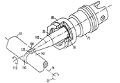
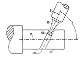
図1は、矢印20で示された方向に中心線15を中心に回転する工作物10を示しており、例えば、この工作物10は旋盤上に取り付けられている。ツールホルダ50には、切削用インサート100が取り付けられている。この切削用インサート100は、中心軸105を有する。この切削用インサート100は、回転しないようにツールホルダ50に保持され、これにより、ツールホルダ50の回転は、切削用インサート100の回転に直接的に変換される。一例として、これらの切削用インサート100及びツールホルダ50は、矢印110で示された方向に回転する。
FIG. 1 shows a
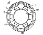
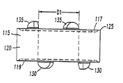
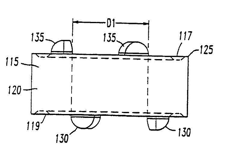
アセンブリの一部は、中心軸105が通って延びるこの切削用インサート100から構成される。この切削用インサートは、図2〜図4に示されているように、頂面117と底面119とこれらの間にある少なくとも1つの側部120とを備えた本体115を有する。この少なくとも1つの側部120と頂面117との交差部において、切削刃125が画定される。切削用インサート100は、ツールホルダ50に取り付けられ、このツールホルダ50は、切削用インサート100をその中心軸105を中心に、10回/分〜装置の限界、好ましくは60〜20,000回/分、より好ましくは250〜10,000回/分の範囲内における所定の回転速度で回転させるように構成されている。この所定の回転速度は、工作物10の回転速度よりも速くても遅くてもよいし、工作物10の回転速度と同じであってもよい。また、この切削用インサート100の回転速度は、金属加工作業中に変更可能であってもよい。さらに、この切削用インサート100の回転速度は、工作物10の回転速度の関数であってもよく、工作物10の回転速度に正比例していてもよい。また、この切削用インサート100の回転速度は、工作物10の回転速度とは完全に独立していてもよい。
Part of the assembly consists of this
一時的に図1に戻ると、ツールホルダ50は、スピンドル75の内部に保持されていてもよく、次に、このスピンドル75は、所望の方向に且つ所望の所定の回転速度でスピンドル75を回転させることのできる工作機械に取り付けられる。ツールホルダ50は、回転工具技術に精通した者に周知の技法であれば、いずれの技法を用いてスピンドル内部に保持されてもよい。しかしながら、図1に示されているように、このスピンドル75は、内側ボア76を有し、この内側ボア76が、ツールホルダ50を受容すると共に、スピンドル75の本体に螺合により保持されてツールホルダ50をスピンドル内部へと付勢するロッキング・ナット80を利用してツールホルダ50をスピンドル75の内部に保持する。ツールホルダをスピンドル内部に保持するこの機構は、回転工具技術に精通した者に周知の機構であれば、多数の異なる機構(コレットやロック・スクリューを含む)のうちのいずれであってもよい。
Returning briefly to FIG. 1, the
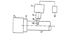
図1Aは、スピンドル75の内部に保持されたツールホルダ50を示している。スピンドル75は、スピンドル・ドライバ77によって駆動される。このスピンドル・ドライバ77からの閉ループ・フィードバックを用いて、コントローラ78が、スピンドル75の回転速度、すなわちツールホルダ50の回転速度を監視して制御する。
FIG. 1A shows the
工作物10は、チャック12によって、工作物10を所定の速度で回転させる旋盤14に固定されていてもよい。このような構造によって、工作物10を所定の速度で回転させることができると共に、切削用インサート100を別個に所定の速度で回転させて切削用インサート100の回転をこの荷重速度に維持することができる。さらに、この切削用インサート100の回転を工作物10の回転と同期させることもできる。旋盤14又はその他の工作機械における工作物10の回転速度を監視して制御する閉ループ・フィードバック・システムを備えるのが、標準的な実施技法である。
The
本発明によるスピンドル75を支持することのできる既存の工作機械には、3つのグループがある。工作機械のこれらのグループはそれぞれ、閉ループ・フィードバック・コントローラを備えることによって、スピンドルの回転速度を厳密に監視して制御することができる。第1のグループは、軸が4つ以上あるマシニング・センタであり、ツールホルダは、スピンドルに保持されスピンドルによって回転される。工作物は、B又はC回転軸によって回転され、ツールホルダは、この回転軸のZ軸方向中央に配置される。ツールホルダは、工作物の直径を回転させるためにY軸方向に送られるか、工作物と対向するためにX軸方向に送られる。
There are three groups of existing machine tools that can support the
工作機械の第2のグループとしては、旋盤/フライス切削複合機械が挙げられる。一般的に旋削/フライス切削複合機械と呼ばれるこのような機械では、ツールホルダはスピンドルによって回転されるが、工作物は主軸台におけるスピンドルによって回転される。ツールホルダは次に工作物のX軸方向中央に配置され、対向動作はY軸方向に行われる。工作物の直径は、ツールホルダをZ軸方向に送ることによって回転される。 The second group of machine tools includes lathe / milling combined machines. In such a machine, commonly referred to as a combined turning / milling machine, the tool holder is rotated by the spindle while the workpiece is rotated by the spindle in the headstock. The tool holder is then placed at the center of the workpiece in the X-axis direction, and the opposing movement is performed in the Y-axis direction. The workpiece diameter is rotated by feeding the tool holder in the Z-axis direction.
可能な工作機械の第3のグループとしては、スピンドルと後方嵌合されてインサートを回転させる従来の2軸旋盤が挙げられる。このスピンドルは、主軸台の中心線及びX軸にほぼ垂直に取り付けられる。対向動作はX軸方向移動によって行われる一方、工作物の直径の回転はZ軸方向移動によって行われる。 A third group of possible machine tools includes conventional two-axis lathes that are fitted back into the spindle to rotate the insert. The spindle is mounted substantially perpendicular to the centerline of the headstock and the X axis. Opposing movement is performed by movement in the X-axis direction, while rotation of the workpiece diameter is performed by movement in the Z-axis direction.
この後方嵌合されたスピンドルは、様々な手段によって駆動することができる。電気サーボ駆動は、コンピュータ数値制御システムに組み込みやすく且つスピンドルの回転速度をプログラミングしやすいという利点を有する一方で、油圧式駆動は、よりコストが安いという利点を有すると共に、工作機械筺体内の悪環境(潤滑剤、切り屑、熱など)において非常に粗雑な構造をもたらす。 This rear fitted spindle can be driven by various means. While the electric servo drive has the advantage of being easy to integrate into a computer numerical control system and programming the spindle rotation speed, the hydraulic drive has the advantage of being cheaper and has a negative impact on the machine tool housing. (Lubricant, chips, heat, etc.) leads to a very rough structure.
図2〜図4に目を向けると、切削用インサート100は、回転しないようにツールホルダ50に保持される。詳細には、切削用インサート100の底面119は、そこから延出する1つ以上の突起130を有し、これらの突起130は、ツールホルダ50の面57にある1つ以上の凹部55と嵌合可能である。切削用インサート100をツールホルダ50の面57に対して付勢することにより、インサートの突起130は、ツールホルダの凹部55と係合して、切削用インサート100とツールホルダ50とを積極結合させ、これにより、切削用インサート100は、ツールホルダ50に保持されて回転することとなる。
2 to 4, the cutting
切削用インサート100は、さらに、底面119にあるこれらの突起130と同一であってもよい1つ以上の突起135を頂面117に有することにより、反転可能であって、どちらの位置においてもツールホルダ50によって積極的に駆動され得る。
The cutting
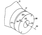
図5に目を向けると、切削用インサート200は、その底面219とツールホルダ50の面57との間の摩擦力だけで、このツールホルダ50の面57に保持されてもよい。切削用インサート200は、その内部を通り中心軸205に沿って延びるボア(図示せず)よりも大きなヘッド232を有する取り付けねじ230を利用し、ツールホルダ50に対して摩擦により付勢されてもよい。この取り付けねじ230は、ツールホルダ50に螺合により保持される。この方式では、切削用インサート200がツールホルダ50に対して付勢されることによって、切削用インサート200とツールホルダ50とが摩擦結合され、ツールホルダ50の回転が切削用インサート200に伝達される。
Turning to FIG. 5, the cutting
本発明による切削用インサートは、金属加工作業で一般的に利用されている材料であれば、いずれの材料からできていてもよく、例としては、スチール、超硬合金、サーメット、セラミック、PCBN(多結晶窒化ホウ素)、PCD(多結晶ダイヤモンド)、及び、ダイヤモンドが挙げられる。これらの材料にはそれぞれ、性能を高めるためにコーティングを施してもよいし施さなくてもよい。この切削用インサートに用いられる材料及び/又はコーティングは、工作物の材料及び切削条件に応じて選択される。 The cutting insert according to the present invention may be made of any material as long as it is a material generally used in metal working operations. Examples thereof include steel, cemented carbide, cermet, ceramic, PCBN ( Polycrystalline boron nitride), PCD (polycrystalline diamond), and diamond. Each of these materials may or may not be coated to enhance performance. The material and / or coating used for this cutting insert is selected according to the workpiece material and cutting conditions.
背景技術において前述したように、これまでは、自由に回転するインサートがツールホルダに取り付けられ、工作物の回転がインサート上に接線方向の力を付与していた。このため、工作物が回転されると、インサートは保持されたツールホルダに対して回転し、これにより、機械加工作業中において、切削用インサートの新しい部分が次々と用いられた。 As described above in the background art, until now, a freely rotating insert was attached to the tool holder, and the rotation of the workpiece applied a tangential force on the insert. For this reason, when the workpiece is rotated, the insert rotates relative to the held tool holder, so that new parts of the cutting insert are used one after another during machining operations.
本発明によれば、切削用インサート100が保持されたツールホルダ50は、工作物10の回転とは完全に独立して回転される。回転する工作物に対して配置された自由に回転する切削用インサートの回転方向は、この切削用インサートの向き並びに工作物の回転速度及び回転方向によって決定されるが、本発明による構造は、これらの可変要素に従属していない。それとは反対に、本発明による構造は、切削用インサート100を、中心軸105を中心にして時計回り又は反時計回りに且つ所望のあらゆる所定の速度で回転させることができる。図1では、切削用インサート100の回転方向は、反時計回り方向に回転するものとして矢印110で示されている。切削用インサート100の回転がこの矢印110で示された回転と反対になるように、ツールホルダ50の回転方向を変更することは十分に可能である。また、回転しないようにツールホルダ50を保持することも可能である。
According to the present invention, the
切削用インサート100の回転方向を決定することによって、切削作業中における切削用インサートにわたる温度分布を管理することができる。例えば、切削用インサート100が矢印110で示された反時計回り方向に回転している場合、切削刃125は、工作物を離れると、切削用インサート100に最大の力及び最高の温度が生じるときである肩領域145に再度入るときまで冷却される。一方、切削用インサート100が(矢印110で示された方向と反対の)時計回り方向に回転している場合には、切削刃125は、肩領域145の前にまず小径部143に沿って工作物と接触し始め、切削作業の最も困難な部分である肩領域145に入るときまで少なくとも部分的に加熱される。従って、これから分かるように、切削作業のエネルギーは、工作物10に対する切削用インサート100の回転方向に応じて変化する。
By determining the direction of rotation of the cutting
切削用インサート10の所定の回転速度を継続することにより、この切削用インサートにわたる熱分布がより均一となり、その結果、この切削用インサートにわたり熱を均一に分散させて、インサート本体内部における応力の一因となる温度変化を最小限に抑えることができる。
By continuing the predetermined rotational speed of the cutting
これまでは、円形をした切削用インサート100及び切削用インサート200に関して述べてきた。このような切削用インサートは、ツールホルダ50が工作物10の中心軸15に対して平行に動かされる限り、断面が円形の機械加工部分をもたらす。しかしながら、断面が非円形の切削用インサートを利用することも十分に可能である。
So far, the
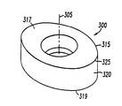
図6に目を向けると、切削用インサート300は、頂面317と、底面319と、頂面317と交差して切削刃325を定める少なくとも1つの側部320とを備えた、本体315を有する。この頂面317は、非円形であり、楕円形をしていてもよい。切削用インサート100(図1)が回転しないようにツールホルダ50に保持されているのと同じように、切削用インサート300も回転しないようにツールホルダ50(図1)に保持されてもよい。このような楕円形の切削用インサート300を収容するには、ツールホルダ50の前端部の形状をわずかに変更しなくてはならないと考えられる。しかしながら、切削刃325にかかる切削負荷に応じて、切削用インサート300は、その底面319全体に沿って支持される必要がある場合もあればない場合もある。いずれにせよ、作業中、楕円形の切削用インサート300の回転を工作物10の回転と同期させることによって、機械加工される工作物自体の断面を非円形としてもよい。一例として、工作物10が1回転する毎に、切削用インサート300がその中心軸305を中心に完全に1回転するようにすると、工作物10の機械加工部分の断面は楕円形となる。一方、この楕円形の切削用インサート300の回転速度を工作物10の回転速度の何倍かにすると、機械加工される工作物10の断面には、円形断面の複数の波形ができる。このような構造は、ねじ山の角度が急なボールねじを製造するのに用いることができる。
Turning to FIG. 6, the cutting
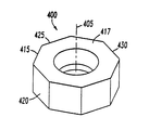
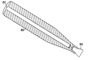
図7は、同じく非円形の切削用インサート400を示している。しかしながら、この設計では、切削用インサート400は、ほぼ八角形の頂面417を備えた本体415を有する。頂面417と側部420とは交差して、ファセット430を有する切削刃425を定める。切削用インサート400のその中心軸405を中心とする回転速度を、工作物10の回転速度に対して制御することによって、例えば、装飾仕上げが施された工作物を生成してもよい。このような形状は、屑の制御にも有用であり得る。
FIG. 7 shows a similarly
特定の金属加工作業の条件に応じて、工作物10から切除された材料から成る切り屑をより小さくする機構を備えた切削用インサートを設計することが望ましい場合もある。詳細には、再度図5に目を向けると、切削用インサート200は、その周辺部周囲にある切削刃225を断続する少なくとも1つの切欠き240を有して、工作物を断続切削してもよい。そうすることによって、この切欠き240は、でき始める切り屑をいずれも分断するか又は分断を促すように機能する。切削刃225の周辺部周囲に複数の切欠き240を設けることも、十分に可能である。しかし、当然のことながら、このような切欠き240の導入によって屑の制御にもたらされる利点は、荒削り作業の場合にのみ当てはまり、工作物10に比較的滑らかな表面仕上げを施す必要がある場合には、連続的な切削刃225を優先して、このような切欠き240は設けなくてもよい。
Depending on the conditions of a particular metalworking operation, it may be desirable to design a cutting insert with a mechanism for making chips made of material cut from the
他の屑制御機構を導入することによって、工作物10から切除された材料から成る切り屑の大きさを制御することも可能である。再度図2〜図4に目を向けると、切削用インサート100の頂面117上の突起135も、切削用インサート100の切削深さが、切削作業中にできる屑をこれらの突起135のうちの1つ以上に当てるのに十分な深さである限り、チップ・ブレーカとして機能し得る。また、突起135の半径方向長さを、切削刃125に近づくように延長することもできる。これらの突起135は、ツールホルダの面57に隣接して配置される場合には、切削用インサート100を回転しないようにツールホルダ50に保持するように位置決めされるが、このインサートの切削深さが浅いときには、金属加工作業中に屑ができるように、半径方向外側に延長することが望ましい場合もある。このような半径方向に延出する突起135のうちの1つ以上に屑が当たることにより、これらの突起135は、ツールホルダの面57に隣接している場合に正回転ロック機構として機能するだけでなく、ツールホルダの面57に面していない場合にはチップ・ブレーカとしても機能する。
It is also possible to control the size of the chips made of material cut from the
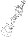
通常、切削用インサートは、回転工具技術に精通した者に周知の機構であれば、様々な機構を用いて、回転しないようにツールホルダ50に保持されてもよい。このような一実施形態が、図2Aに示されている。コレット85が、ツールホルダ50の内部を延びるボア87に取り付けられ、切削用インサート100は、このコレット85を介してツールホルダ50に保持され得る。詳細には、図2Aに示されたこの実施形態に関し、切削用インサートの本体115は、その内部を通り中心軸105に沿って延びるボア137を有する。このボア137は、内径D1(図2A)の内壁140(図3)を有する。コレット85は、中心軸105と位置合わせされ、回転しないようにツールホルダ50のボア87に保持されると共にこのボア87から突出する。このコレット85は、内側ねじ切りボア89と、最大外径D2(図2A)がインサートのボアの最大内径D1よりも小さい外壁86とを有していてもよい。このコレットの内側ねじ切りボア89には、ボルト90が螺合により固定可能である。従って、コレット85がツールホルダ50のボア87に取り付けられた状態において、切削用インサート100がコレット85の上に配置され、ボルト90が切削用インサート100のボア137を通して配置される。このボルトは、次に、コレット85のねじ切りボア89と螺合により係合し、これにより、切削用インサート100がコレットの外壁86上に取り付けられた状態において、インサートのボア137がコレットの外壁86上に嵌合する。次に、このボルト90が締め付けられることによって、コレット85は拡張し、その外壁86を切削用インサートのボアの内壁140に対して保持する。その結果、切削用インサート100は、回転しないようにツールホルダ50に保持される。
In general, the cutting insert may be held by the
図2及び図2Aに示されたコレット85は、一定の外径D2を有して円形を画定している。当然のことながら、このコレットの形状は円形に限定されず、別の非円形のコレットを収容するように切削用インサート100の内壁140を変更しなくてはならないということを理解した上であれば、様々な非円形のコレットのいずれを用いてもよい。しかしながら、このような収容に関する詳細は、回転工具技術に精通した者には周知のことである。一例として、このコレットは、楕円形の外面を有して、楕円形の切削用インサートと嵌合してもよい。
The
コレット85は、図2Aでは取り外し可能にツールホルダ50に保持されているが、ツールホルダ50の内部に永久的に取り付けられるか又はツールホルダ50の一体部品であることも可能である。
Although the
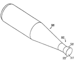
図8に示されているように、ツールホルダ/切削用インサート500は、1つの一体部品である。このツールホルダ/切削用インサート500は、前述したツールホルダ50と同じ特徴を全て備えているが、切削用インサートがツールホルダ50の端部から分離しているのではなくこの端部に回転しないように保持されており、交差して切削刃525を形成する頂面517と側部520とを備えた切削端部502を有する。このような状況下では、ツールホルダ/切削用インサート500の切削端部502を繰り返し研ぐことによって、予期せぬ損傷がない限り工具寿命が非常に長い一体型のツールホルダ/切削用インサート500が提供される。
As shown in FIG. 8, the tool holder /
これまで述べてきた取り外し可能な切削用インサートはほぼ円盤形をしていたが、インサートの頂面及び少なくとも1つの側部が本明細書中で述べた特徴を備える限り、異なる形状をしたインサートを用いることもできる。 Although the removable cutting inserts described so far have been generally disk-shaped, differently shaped inserts can be used as long as the top surface and at least one side of the insert have the features described herein. It can also be used.
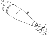
詳細には、図9は、頂面617と、底面619と、頂面617と交差して切削刃625を画定する側部620とを備えた、柱状の切削用インサート600を示している。この切削用インサート600は、截頭円錐形の支柱630を有し、この支柱630がツールホルダ900内部の嵌合ボア650に嵌合することによって、支柱630と嵌合ボア650とが摩擦嵌合される。このような方式では、切削用インサート600は、回転しないようにツールホルダ900の内部に保持される。この構造は、機械加工作業中に切削用インサート600に生じる力が切削刃625に作用することにより、コンポーネントをツールホルダの中心軸952に沿った状態にする圧縮力がもたらされる場合に、特に適している。
Specifically, FIG. 9 shows a
背景技術において、回転しないインサートの工具故障モードは、インサートの切削刃における1つの特定箇所に温度及び力が集中することによって生じるクレータ摩耗及び塑性変形であるとした。本発明によるこの設計は、従来技術の金属切削条件のこのような故障モードを最小限に抑える一方で、熱を切削用インサートからツールホルダへ非常に効果的に伝達することによりツールホルダを過剰温度で損傷させてしまう可能性がある。従って、このツールホルダには、冷却機構を導入することが望ましい場合もある。 In the background art, the tool failure mode of a non-rotating insert is assumed to be crater wear and plastic deformation caused by concentration of temperature and force at one specific location on the cutting edge of the insert. This design according to the present invention minimizes such failure modes of prior art metal cutting conditions while overheating the tool holder by transferring heat from the cutting insert to the tool holder very effectively. May cause damage. Therefore, it may be desirable to introduce a cooling mechanism into the tool holder.
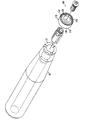
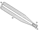
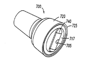
図10に目を向けると、変形されたツールホルダ750は、その長さに沿って延びるボア755を有し、このボア755を通して、潤滑剤が供給され得る。取り付けられる切削用インサート700は、このボア755に保持され、切削用インサート700自体は、ツールホルダ750内部のこのボア755と同一直線上にあり得るボア705を有する。切削作業中にボア755を介して導入された潤滑剤は、切削用インサート700のこのボア705を通って進み、切削領域付近において流出する。このように、潤滑剤は、切削領域を冷却すると共に、さらに、ツールホルダ750及び切削用インサート700を冷却するのに利用され得る。
Turning to FIG. 10, the modified
切削用インサート700の細部が、図11に示されている。切削用インサート700は頂面717及び側部720を有し、これらは交差して切削刃725を画定する。切削用インサート700の長さに沿って延びるボア705は、ツールホルダ750のボア755(図10)と流体連結している。チップ・ブレーカ740が、インサートの頂面717の幅にわたって延びており、図3及び図4の突起130及び135と同様の方式で、金属加工作業中における切り屑の生成を促すのに用いられる。
Details of the cutting
図10は、直径が一定のボア705を示している。実際の切削領域上に潤滑流体をより適切に拡散させるため、図12に示されているように、同様の切削用インサート800において、そのボア805の流出部810は、ボアが頂面817に近づくにつれて外側に傾斜する内壁812を備えていてもよい。このようなほぼ円錐形をした内壁812は、より幅の広い散布領域を介して潤滑流体を効果的に拡散するように機能することによって、切削領域をより効果的に冷却する。この方式では、切削作業によって生じてツールホルダに伝達された熱が効果的に除去され得ると同時に、潤滑流体が切削領域を冷却するように機能する。
FIG. 10 shows a
ツールホルダを通って延びる潤滑剤用のボアを設けることに加えて、ツールホルダを構成する耐熱性材料を選択することも可能である。一例として、このツールホルダ材料は、インコネルであってもよいし、十分な構造剛性をもたらすと共に耐熱性のある材料であれば、他のいずれの材料であってもよい。 In addition to providing a lubricant bore extending through the tool holder, it is also possible to select a heat resistant material that constitutes the tool holder. As an example, the tool holder material may be Inconel, or any other material that provides sufficient structural rigidity and is heat resistant.
乾式切削作業が必要とされて潤滑剤が工作物に導入されない場合は、図13に示されているように、ツールホルダ850のボア855を、ツールホルダ850の長さの一部だけに沿って延びるようにすることもできる。このボア855に導入される潤滑剤は、加熱されたら、他の潤滑流体で循環させなくてはならない。このような循環は、切削用インサート800を高い位置に維持し、ボア855を通して潤滑流体を散布することによって行うことができ、この潤滑流体は、次に、重力によってツールホルダ850の反対側の端部に戻る。別の方法では、例えば、切削用インサート800がアセンブリの最も低い部分である場合、潤滑流体は、蒸発してボア855の反対側の端部に進み、そこで冷却されて液化され得る。
If a dry cutting operation is required and no lubricant is introduced into the workpiece, the
図13には示されていないが、ツールホルダ850の長さ全体にわたってボア855を延長し、さらに、切削用インサート800の一部にわたってボアを取り込むことも十分に可能であり、これによって、ボア855に導入される潤滑流体はいずれも、このインサートのボアにも導入され、ツールホルダ850と切削用インサート800との両方が冷却される。ツールホルダ850を部分的に通って延びるボア855を備えた構造と同様に、切削用インサートを部分的に通って延びると共にツールホルダのボアと連通するボア855を備えたこのような構造も、ツールホルダを動かすことによってその内部の潤滑流体を攪拌することができ、これにより、ツールホルダ850及び切削用インサート800にわたってより均一に熱が分散され、熱放散が高まる。また、図13の切削用インサート800と同様のインサートを用いて、図10のツールホルダ750を通って延びるボアを「塞ぐ」こともできる。
Although not shown in FIG. 13, it is possible to extend the
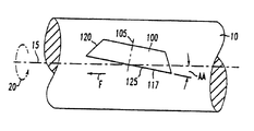
図14に目を向けると、切削用インサート100は、頂面117と、この頂面117と交差して切削刃125を定める側部120とを有し、切削刃125における頂面117と工作物10の軸15から延びる放射状の線Rとの交差部において形成されるすくい角RAが−10°〜+30°、好ましくは−5°〜+15°となるように、工作物10に対して方向付けされ得る。多くの場合、切削刃から内側に延びるランドがあり、このランドの角度によって切削用インサートのすくい角RAが正、0、又は負となる。このような状況下では、すくい角RAは、ランドの角度(すくい面の角度)と切削用インサートの角度方向とを組み合わせたものである。図14に示されているように、工作物10は、軸15を中心に矢印20の方向に回転している。
Turning to FIG. 14, the cutting
図15に目を向けると、切削用インサート100は、切削刃125における頂面117と工作物10の軸15とが交差して、90°より小さい、好ましくは0°〜30°の軸角AAを形成するように、送り方向Fに対して方向付けされてもよい。以下の表に見られる実施例は、本発明によるアセンブリを利用した結果を示している。
Turning to FIG. 15, the cutting
0.5インチのICを備えた円形インサートを、本発明の図9の構造と同様の方式でツールホルダに保持し、森精機(Mori Seiki)のMT253工作機械に取り付けた。この実施例は、乾燥状態において行った。切削用インサートは、コーティングされた超硬合金KC8050であった。このKC8050という銘柄は、ケンナメタル(Kennametal)社が生み出した独占銘柄である。工作物は、1040炭素鋼でできた開始時の直径およそ6インチのログであった。 A circular insert with a 0.5 inch IC was held in a tool holder in a manner similar to the structure of FIG. 9 of the present invention and attached to a Mori Seiki MT253 machine tool. This example was performed in the dry state. The cutting insert was a coated cemented carbide KC8050. The KC8050 brand is an exclusive brand created by Kennametal. The workpiece was an approximately 6 inch diameter log made of 1040 carbon steel.
これまで述べてきたのは、回転しないようにスピンドル内部に保持されたツールホルダであって、スピンドルの回転がツールホルダの回転に変わり、このツールホルダの回転が切削用インサートの回転に変わる。この構造では、スピンドルを回転させることが必要とされる。一方、保持されたスピンドルと、補助的な駆動機構、例えば、このスピンドルに取り付けられ、このスピンドル内部のツールホルダを回転させることのできるモータ、とを利用することも、十分に可能である。 What has been described so far is the tool holder held inside the spindle so as not to rotate. The rotation of the spindle changes to the rotation of the tool holder, and the rotation of the tool holder changes to the rotation of the cutting insert. With this structure, it is necessary to rotate the spindle. On the other hand, it is sufficiently possible to use a held spindle and an auxiliary drive mechanism, for example, a motor attached to the spindle and capable of rotating a tool holder inside the spindle.
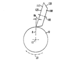
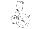
また、本発明の装置を利用することによって、工作物の重ね幅にわたって材料を切除する前述した旋盤作業ではなく、ねじ山を作るように工作物を機械加工することも可能である。図16及び図17は、ねじ山を作るように工作物が機械加工される構造を示している。このようにねじ山を作るには、インサートの送り速度と工作物の回転とを厳密に同期させることが必要とされる。ツールホルダ50に保持された切削用インサート100は、その中心軸105が工作物10の中心線15と角Zを成すように方向付けられる。さらに、切削用インサート100の中心軸105に対して垂直な線は、工作物の中心線15から延びる放射状の線Rと逃げ角Yを成す。
Also, by utilizing the apparatus of the present invention, it is possible to machine a workpiece to create a thread, rather than the lathe operation described above, which cuts material across the stack width of the workpiece. 16 and 17 show the structure in which the workpiece is machined to create a thread. In order to make a thread in this way, it is necessary to precisely synchronize the feed rate of the insert and the rotation of the workpiece. The cutting
一例では、工作物10は、4140合金鋼でできている。逃げ角Yは7°であり、角Zも7°である。0.5インチのICを備えた円形インサートである切削用インサート100は、スピンドルの回転軸Bに対して垂直に方向付けられる。工作物10の回転速度は100回転/分であるのに対し、切削用インサート100の回転速度はその2倍、即ち200回転/分である。切削用インサート100の送り速度は、ねじ山の所望のピッチに等しく、3インチ/回転である。切削深さは、0.010インチである。このような状況下では、金属の切除速度は、6立方インチ/分である。
In one example, the
本発明の特定の実施形態に関して詳細に説明してきたが、この開示の全体的な教示を考慮した上でこれらの細部に対し様々な変更及び代替を行うことができる、ということは当業者には認められるであろう。本明細書中で説明したこの好適な実施形態は、単に例示することを意図したに過ぎず、本発明の範囲を制限することを意図したのではない。本発明の範囲は、添付の特許請求の範囲の全範囲及びそのあらゆる全ての等価物に及ぶ。 Although described in detail with respect to particular embodiments of the present invention, those skilled in the art will recognize that various changes and substitutions can be made to these details in light of the overall teachings of this disclosure. Will be recognized. This preferred embodiment described herein is intended to be exemplary only and is not intended to limit the scope of the invention. The scope of the present invention extends to the full scope of the appended claims and any and all equivalents thereof.
Claims (4)
1)頂面及び底面と、
2)前記頂面と前記底面との間に前記本体の全体の周囲に延びる少なくとも1つの側部と、
3)前記少なくとも1つの側部と前記頂面との交差部の全体に沿って延びる切削刃であって、複数の隣接する円周断面により形成される前記切削刃の円周を区画し、前記切削刃の円周が1つの平面上にある切削刃と、
を有する、切削用インサートと、
b)前記切削用インサートが取り付けられた回転可能なツールホルダであって、前記中心軸を中心に前記切削用インサートを所定の回転速度で回転させ、前記切削刃の前記隣接する円周断面が前記工作物に連続的に向けられる、ツールホルダと、
から成る、アセンブリであって、
c)前記切削用インサートが、楕円形状であり、前記工作物をその断面が非円形となるように成形する、
アセンブリ。 a) a cutting insert comprising a main body and having a central axis extending therethrough, the workpiece being machined by rotating the cutting insert about the central axis;
1) top and bottom surfaces;
2) at least one side extending around the entire body between the top surface and the bottom surface;
3) A cutting blade extending along the entire intersection of the at least one side portion and the top surface, and defining a circumference of the cutting blade formed by a plurality of adjacent circumferential cross sections, A cutting blade whose circumference is on one plane;
A cutting insert having
b) A rotatable tool holder to which the cutting insert is attached, wherein the cutting insert is rotated at a predetermined rotational speed around the central axis, and the adjacent circumferential section of the cutting blade is A tool holder that is continuously directed to the workpiece;
An assembly comprising:
c) The cutting insert has an elliptical shape, and the workpiece is shaped so that its cross section is non-circular.
assembly.
1)頂面及び底面と、
2)前記頂面と前記底面との間に前記本体の全体の周囲に延びる少なくとも1つの側部と、
3)前記少なくとも1つの側部と前記頂面との交差部の全体に沿って延びる切削刃であって、複数の隣接する円周断面により形成される前記切削刃の円周を区画し、前記切削刃の円周が1つの平面上にある切削刃と、
を有する、切削用インサートと、
b)前記切削用インサートが取り付けられた回転可能なツールホルダであって、前記中心軸を中心に前記切削用インサートを所定の回転速度で回転させ、前記切削刃の前記隣接する円周断面が前記工作物に連続的に向けられる、ツールホルダと、
から成る、アセンブリであって、
c)ボアが前記ツールホルダ内部を延びると共に完全に閉鎖されており、流体が前記ボアを部分的に満たすことによって、前記ツールホルダの動きが前記流体を攪拌し、これにより、前記ツールホルダにわたってより均一に熱が分散されて、熱放散が高まる、
アセンブリ。 a) a cutting insert comprising a main body and having a central axis extending therethrough, the workpiece being machined by rotating the cutting insert about the central axis;
1) top and bottom surfaces;
2) at least one side extending around the entire body between the top surface and the bottom surface;
3) A cutting blade extending along the entire intersection of the at least one side portion and the top surface, and defining a circumference of the cutting blade formed by a plurality of adjacent circumferential cross sections, A cutting blade whose circumference is on one plane;
A cutting insert having
b) A rotatable tool holder to which the cutting insert is attached, wherein the cutting insert is rotated at a predetermined rotational speed around the central axis, and the adjacent circumferential section of the cutting blade is A tool holder that is continuously directed to the workpiece;
An assembly comprising:
c) The bore extends inside the tool holder and is completely closed, so that the fluid partially fills the bore so that the movement of the tool holder agitates the fluid and thereby more over the tool holder. Heat is evenly distributed, increasing heat dissipation,
assembly.
a)前記中心軸と回転する工作物の長手方向軸とが角度を成すように、前記切削用インサートを位置合わせするステップと、
b)ドライバの回転により、前記切削用インサートを、前記切削用インサートの前記中心軸を中心に所定の速度で回転させるステップと、
c)前記ドライバにより前記切削用インサートが回転する際に、前記切削用インサートを前記工作物に対して付勢して機械加工作業を開始する、ステップと、
を含み、
d)前記切削用インサートの前記頂面が非円形であり、
前記切削用インサートの回転を前記工作物の回転と同期させて、前記工作物の断面を非円形に加工するステップをさらに含む、機械加工方法。 A main body, the main body having a top surface and a bottom surface, at least one side portion extending around the entire body between the top surface and the bottom surface, the at least one side portion and the top surface; A cutting blade extending across the entire crossing section of the cutting blade, defining a circumference of the cutting blade formed by a plurality of adjacent circumferential cross sections, and the cutting blade having a circumference on a single plane; Using a cutting insert comprising a central axis extending through the top surface and the bottom surface,
a) aligning the cutting insert such that the central axis and the longitudinal axis of the rotating workpiece form an angle;
b) rotating the cutting insert at a predetermined speed around the central axis of the cutting insert by rotation of a driver;
c) urging the cutting insert against the workpiece when the cutting insert is rotated by the driver to start a machining operation;
Including
d) the top surface of the cutting insert is non-circular;
A machining method further comprising the step of processing the cross section of the workpiece into a non-circular shape by synchronizing the rotation of the cutting insert with the rotation of the workpiece.
1)頂面及び底面と、
2)前記頂面と前記底面との間にある側部と、
3)前記少なくとも1つの側部と前記頂面との交差部にある切削刃と、
を有する、切削用インサートと、
b)前記切削用インサートが取り付けられたツールホルダであって、前記中心軸を中心に前記切削用インサートを所定の回転速度で回転させる、ツールホルダと、
から成る、アセンブリであって、
c)前記切削用インサートの前記底面が、前記底面から延出する突起を有し、前記突起が、前記ツールホルダの凹部と嵌合可能であり、前記切削用インサートが前記ツールホルダに対して付勢されると、前記切削用インサートと前記ツールホルダとが積極結合され、前記切削用インサートが回転方向に前記ツールホルダに保持され、
前記切削用インサートが、前記底面の前記突起と同一の突起を前記頂面にさらに含むことによって、反転可能であって、どちらの位置においても前記ツールホルダによって確実駆動され得る、
アセンブリ。 a) a cutting insert comprising a main body and having a central axis extending therethrough, the main body comprising:
1) top and bottom surfaces;
2) a side portion between the top surface and the bottom surface;
3) a cutting blade at the intersection of the at least one side and the top surface;
A cutting insert having
b) a tool holder to which the cutting insert is attached, the tool holder rotating the cutting insert at a predetermined rotational speed around the central axis;
An assembly comprising:
c) The bottom surface of the cutting insert has a protrusion extending from the bottom surface, the protrusion can be fitted into a recess of the tool holder, and the cutting insert is attached to the tool holder. When it is biased, the cutting insert and the tool holder are positively coupled, and the cutting insert is held in the tool holder in the rotational direction,
The cutting insert further includes a protrusion on the top surface that is the same as the protrusion on the bottom surface, so that the cutting insert can be reversed and can be reliably driven by the tool holder at either position.
assembly.
Applications Claiming Priority (2)
| Application Number | Priority Date | Filing Date | Title |
|---|---|---|---|
| US10/653,712 US7156006B2 (en) | 2003-09-02 | 2003-09-02 | Method and assembly for rotating a cutting insert during a turning operation and inserts used therein |
| US10/653,712 | 2003-09-02 |
Related Parent Applications (1)
| Application Number | Title | Priority Date | Filing Date |
|---|---|---|---|
| JP2006525348A Division JP2007504011A (en) | 2003-09-02 | 2004-08-18 | Insert assembly for rotary cutting and method of using the same |
Publications (1)
| Publication Number | Publication Date |
|---|---|
| JP2012024925A true JP2012024925A (en) | 2012-02-09 |
Family
ID=34217954
Family Applications (3)
| Application Number | Title | Priority Date | Filing Date |
|---|---|---|---|
| JP2006525348A Pending JP2007504011A (en) | 2003-09-02 | 2004-08-18 | Insert assembly for rotary cutting and method of using the same |
| JP2011243423A Pending JP2012024925A (en) | 2003-09-02 | 2011-11-07 | Rotating cutting insert assembly, and method of using the same |
| JP2011243424A Expired - Fee Related JP5519616B2 (en) | 2003-09-02 | 2011-11-07 | Insert assembly for rotary cutting and method of using the same |
Family Applications Before (1)
| Application Number | Title | Priority Date | Filing Date |
|---|---|---|---|
| JP2006525348A Pending JP2007504011A (en) | 2003-09-02 | 2004-08-18 | Insert assembly for rotary cutting and method of using the same |
Family Applications After (1)
| Application Number | Title | Priority Date | Filing Date |
|---|---|---|---|
| JP2011243424A Expired - Fee Related JP5519616B2 (en) | 2003-09-02 | 2011-11-07 | Insert assembly for rotary cutting and method of using the same |
Country Status (6)
| Country | Link |
|---|---|
| US (2) | US7156006B2 (en) |
| EP (1) | EP1660260B1 (en) |
| JP (3) | JP2007504011A (en) |
| KR (1) | KR101142081B1 (en) |
| CN (1) | CN100398236C (en) |
| WO (1) | WO2005021191A2 (en) |
Cited By (1)
| Publication number | Priority date | Publication date | Assignee | Title |
|---|---|---|---|---|
| JP2012024926A (en) * | 2003-09-02 | 2012-02-09 | Kennametal Inc | Rotating cutting insert assembly, and method for using the same |
Families Citing this family (68)
| Publication number | Priority date | Publication date | Assignee | Title |
|---|---|---|---|---|
| US8573901B2 (en) * | 2003-09-02 | 2013-11-05 | Kennametal Inc. | Assembly for rotating a cutting insert during a turning operation and inserts used therein |
| US7325471B2 (en) * | 2004-09-07 | 2008-02-05 | Kennametal Inc. | Toolholder and cutting insert for a toolholder assembly |
| AT8511U1 (en) * | 2005-04-05 | 2006-09-15 | Ceratizit Austria Gmbh | TOOL CONSTRUCTION |
| DE102005035576A1 (en) * | 2005-07-29 | 2007-02-01 | Fms Drehtechnik Schaffhausen Ag | Production of threads for drill strings comprises mechanically producing a radial oscillation movement between a rotating tool and the workpiece |
| DE202005012862U1 (en) * | 2005-08-12 | 2006-12-21 | Kennametal Widia Produktions Gmbh & Co. Kg | cutting tool |
| US7604073B2 (en) * | 2005-10-11 | 2009-10-20 | Us Synthetic Corporation | Cutting element apparatuses, drill bits including same, methods of cutting, and methods of rotating a cutting element |
| US7845436B2 (en) | 2005-10-11 | 2010-12-07 | Us Synthetic Corporation | Cutting element apparatuses, drill bits including same, methods of cutting, and methods of rotating a cutting element |
| DE102005051695A1 (en) * | 2005-10-28 | 2007-05-03 | Bernhard Albert | Milling and / or turning tool as well as milling and / or turning method |
| US20070274794A1 (en) * | 2006-05-26 | 2007-11-29 | Cirino Thomas J | Oblique angle serration location and drive interface |
| US20080025808A1 (en) | 2006-07-25 | 2008-01-31 | Mori Seiki Usa, Inc. | Compound Machining Method and Apparatus |
| DE112007002134T5 (en) | 2006-09-11 | 2009-07-09 | Mori Seiki U.S.A., Inc., Rolling Meadows | Turning procedure and device |
| MX2009010171A (en) * | 2007-03-23 | 2010-02-24 | Kennametal Inc | Method and assembly for rotating a cutting insert during a turning operation and inserts used therein. |
| JP2008240825A (en) * | 2007-03-26 | 2008-10-09 | Ntn Corp | Machining method, trunnion and tripod type constant velocity universal joint |
| SE531363C2 (en) * | 2007-03-30 | 2009-03-10 | Seco Tools Ab | Cutting tool with interchangeable cutting support cassette |
| EP2514560B1 (en) * | 2007-06-06 | 2015-08-05 | No Screw Ltd. | Cutting tool |
| US20090052999A1 (en) * | 2007-08-24 | 2009-02-26 | Aggressive Equipment, Inc. | Cutting insert and method |
| WO2009089300A2 (en) * | 2008-01-07 | 2009-07-16 | Rotary Technologies Corporation | Rotary metal-cutting insert and mounting cartridge therefor |
| DE102008037915B3 (en) | 2008-08-14 | 2009-08-13 | Kennametal Inc. | Indexable insert |
| WO2010035475A1 (en) * | 2008-09-25 | 2010-04-01 | 三菱マテリアル株式会社 | Rotary cutting tool |
| US8408837B2 (en) * | 2008-10-31 | 2013-04-02 | Fisher Controls International, Llc | Collets for use with valves |
| US8205633B2 (en) * | 2008-10-31 | 2012-06-26 | Fisher Controls International, Llc | Collets for use with valves |
| WO2010092574A1 (en) * | 2009-02-11 | 2010-08-19 | Simatate Ltd. | Multi-edge cutting head and an insert used therein |
| US8079431B1 (en) | 2009-03-17 | 2011-12-20 | Us Synthetic Corporation | Drill bit having rotational cutting elements and method of drilling |
| DE112010002745T5 (en) * | 2009-05-04 | 2013-06-27 | Mori Seiki Co., Ltd. | System and method for synchronized editing |
| KR101606935B1 (en) * | 2009-07-09 | 2016-03-28 | 대구텍 유한회사 | Assembly of double-sided indexable cutting insert and reinforced part |
| IL199936A0 (en) * | 2009-07-19 | 2010-04-15 | Iscar Ltd | Rotary cutting tool and cutting insert therefor |
| KR101675397B1 (en) * | 2009-07-31 | 2016-11-11 | 뵈린게 이노베이션 에이비이 | Methods and arrangements relating to edge machining of building panels |
| JP5512386B2 (en) | 2009-09-25 | 2014-06-04 | Dmg森精機株式会社 | Cylindrical rotary tool having flow path in tool and machining method using this tool |
| WO2011047126A1 (en) | 2009-10-15 | 2011-04-21 | Sandvik, Inc. | Multiteeth indexable insert with locating means and material removal tool with same |
| US8573903B2 (en) | 2009-11-03 | 2013-11-05 | Kennametal Inc. | Round cutting insert with anti-rotation feature |
| US8388274B2 (en) | 2010-01-06 | 2013-03-05 | Kennametal Inc. | Round cutting insert with asymmetric chipbreaker feature |
| JP5793507B2 (en) * | 2010-01-07 | 2015-10-14 | ジーケーエヌ シンター メタルズ、エル・エル・シー | Machine tool and method for manufacturing the machine tool |
| JP5534509B2 (en) * | 2010-02-03 | 2014-07-02 | オークマ株式会社 | Cutting method |
| US8887838B2 (en) * | 2010-02-05 | 2014-11-18 | Baker Hughes Incorporated | Cutting element and method of orienting |
| US8997899B2 (en) | 2010-02-05 | 2015-04-07 | Baker Hughes Incorporated | Cutting element, cutter tool and method of cutting within a borehole |
| SE534651C2 (en) * | 2010-02-12 | 2011-11-08 | Sandvik Intellectual Property | Cutting, tool part, procedure and machine tool for chip cutting metal machining |
| US20110262232A1 (en) * | 2010-04-23 | 2011-10-27 | Chin-Chiu Chen | Lathe blade assembly |
| USD659729S1 (en) | 2010-06-23 | 2012-05-15 | Kennametal Inc. | Toolholder |
| US8459904B2 (en) * | 2010-06-23 | 2013-06-11 | Kennametal Inc. | Cutting insert and holder for rotating applications |
| US8657539B2 (en) * | 2011-03-28 | 2014-02-25 | Kennametal Inc. | Round cutting insert with reverse anti-rotation feature |
| RU2463130C1 (en) * | 2011-07-12 | 2012-10-10 | Федеральное государственное автономное образовательное учреждение высшего профессионального образования Сибирский федеральный университет (СФУ) | Rotary cutter |
| WO2013051703A1 (en) * | 2011-10-07 | 2013-04-11 | 株式会社タンガロイ | Cutting tool with replaceable blade edge |
| US8950516B2 (en) | 2011-11-03 | 2015-02-10 | Us Synthetic Corporation | Borehole drill bit cutter indexing |
| USD709110S1 (en) | 2012-04-24 | 2014-07-15 | Kennametal Inc. | Cutting insert |
| US8858130B2 (en) | 2012-04-24 | 2014-10-14 | Kennametal Inc. | Indexable circular cutting insert |
| US9580970B2 (en) | 2012-06-22 | 2017-02-28 | Baker Hughes Incorporated | Cutting element, tool and method of cutting within a borehole |
| US9546520B2 (en) | 2012-06-22 | 2017-01-17 | Baker Hughes Incorporated | Cutting element, tool and method of cutting within a borehole |
| US9776251B2 (en) | 2012-08-10 | 2017-10-03 | Sumitomo Electric Hardmetal Corp. | Lathe turning tool |
| RU2514243C1 (en) * | 2012-09-26 | 2014-04-27 | Михаил Борисович Мельников | Method of cutting and device to this end |
| JP6379623B2 (en) * | 2013-05-13 | 2018-08-29 | 株式会社ジェイテクト | Cutting apparatus and cutting method |
| EP2818268B1 (en) * | 2013-06-26 | 2017-05-10 | VARGUS Ltd. | Cutting insert and a tool holder with a seat for cutting insert |
| US9817387B2 (en) | 2013-07-08 | 2017-11-14 | Kennametal Inc | System and method for selecting a tool assembly |
| US20150025672A1 (en) * | 2013-07-18 | 2015-01-22 | Kennametal Inc. | System and method for selecting cutting tools |
| JP6669983B2 (en) * | 2014-06-27 | 2020-03-18 | 株式会社ジェイテクト | Cutting device and cutting method |
| JP6645041B2 (en) * | 2015-06-23 | 2020-02-12 | 株式会社ジェイテクト | Cutting device and cutting method |
| JP6315350B2 (en) | 2015-10-23 | 2018-04-25 | 住友電工ハードメタル株式会社 | Rotary cutting tool |
| JP7035464B2 (en) * | 2017-01-20 | 2022-03-15 | 株式会社ジェイテクト | Cutting method and cutting equipment |
| CN106862592B (en) * | 2017-03-27 | 2018-09-14 | 歌尔股份有限公司 | A kind of processing method of workpiece |
| EP3501701B1 (en) * | 2017-12-22 | 2020-07-29 | Ceratizit Austria Gesellschaft m.b.H. | Tool system and method for turning |
| EP3536427B1 (en) * | 2018-03-08 | 2022-08-17 | AB Sandvik Coromant | Turning tool and turning method for cnc-machines |
| EP3536425B1 (en) * | 2018-03-08 | 2023-08-16 | AB Sandvik Coromant | Turning method for a cnc-lathe |
| RU2685824C1 (en) * | 2018-08-09 | 2019-04-23 | Общество с ограниченной ответственностью "ТРИАДА" | Cutter for rotary turning |
| EP3738698B1 (en) * | 2019-05-16 | 2022-11-02 | AB Sandvik Coromant | Turning insert for metal cutting, a cutting tool and a method to machine a metal workpiece |
| JP7507465B2 (en) * | 2019-07-11 | 2024-06-28 | 三菱鉛筆株式会社 | Ballpoint pen tip, ballpoint pen manufacturing method, and spindle |
| US12544841B2 (en) | 2021-04-26 | 2026-02-10 | Kennametal Inc. | Cutting tool comprising toolholder and round cutting insert and method for repositioning the round cutting insert in a pocket of the toolholder |
| US11786982B2 (en) | 2021-04-26 | 2023-10-17 | Kennametal Inc. | Cutting tool comprising toolholder and round cutting insert and method for repositioning the round cutting insert in a pocket of the toolholder |
| JP7801567B2 (en) * | 2022-02-16 | 2026-01-19 | 株式会社不二越 | Turning tools for multitasking machines |
| CN114453930B (en) * | 2022-04-07 | 2022-06-28 | 宁波佳比佳智能科技有限公司 | Rotary clamping device |
Citations (6)
| Publication number | Priority date | Publication date | Assignee | Title |
|---|---|---|---|---|
| JPS5249983U (en) * | 1975-10-08 | 1977-04-09 | ||
| JPS61111801A (en) * | 1984-11-06 | 1986-05-29 | Mitsubishi Heavy Ind Ltd | Throw-away tool |
| JPS6344703U (en) * | 1986-09-11 | 1988-03-25 | ||
| JPH0691406A (en) * | 1992-09-10 | 1994-04-05 | Nissan Motor Co Ltd | Cutting tool |
| JP2000015501A (en) * | 1998-06-30 | 2000-01-18 | Mitsubishi Heavy Ind Ltd | Internally cooling type rotary cutting device |
| JP2012024926A (en) * | 2003-09-02 | 2012-02-09 | Kennametal Inc | Rotating cutting insert assembly, and method for using the same |
Family Cites Families (46)
| Publication number | Priority date | Publication date | Assignee | Title |
|---|---|---|---|---|
| US2206770A (en) | 1938-12-19 | 1940-07-02 | Nat Broach & Mach | Surface shaving |
| LU27984A1 (en) | 1943-04-14 | |||
| CH244896A (en) | 1945-02-15 | 1946-10-15 | E Dr Corridori | Process for the machining of workpieces. |
| FR1065881A (en) | 1952-11-04 | 1954-05-31 | Lathe Tool | |
| US3037264A (en) * | 1959-09-08 | 1962-06-05 | Carl W Mossberg | Coolant type milling cutter |
| US3299491A (en) * | 1965-10-19 | 1967-01-24 | Teller B Hall | Cutting tool |
| US3339032A (en) | 1966-03-16 | 1967-08-29 | Cutler Hammer Inc | Positive action switches with improved sliding contact supporting rail structure |
| USRE26637E (en) * | 1967-11-13 | 1969-07-29 | Rotary cutter and method | |
| US3656377A (en) * | 1969-07-10 | 1972-04-18 | Allen Bradley Co | Surface speed control of spindle-related numerical control system |
| US3925868A (en) * | 1974-06-21 | 1975-12-16 | Mccrosky Tool Corp | Clamping assembly for cutter bits |
| JPS5249983A (en) | 1975-10-20 | 1977-04-21 | Nippon Soda Co Ltd | Adsorption method with active carbon |
| US4024777A (en) * | 1976-06-03 | 1977-05-24 | Derrell Jean Fogarty | Automatically indexable cutting tool |
| GB1582639A (en) * | 1976-09-21 | 1981-01-14 | Lucas Industries Ltd | Tool assembly for and a method of effecting a rotary turning operation |
| SU753540A1 (en) * | 1977-04-19 | 1980-08-07 | Физико-технический институт АН Белорусской ССР | Method of cutting with self-rotating cutter |
| GB2057939B (en) | 1979-09-04 | 1982-11-24 | Univ Western Australia | Method of machining and a rotary cutting tool therefor |
| US4477211A (en) | 1980-03-13 | 1984-10-16 | Briese Leonard A | Rotary tool cutting cartridge |
| EP0121441A3 (en) * | 1983-04-04 | 1985-11-06 | General Electric Company | Improved insert for a metal cutting tool |
| US4621955A (en) * | 1984-04-16 | 1986-11-11 | Briese Leonard A | Cone shaped cutting insert |
| US4720216A (en) * | 1985-01-18 | 1988-01-19 | Smith Robert S | Cylindrical cutting tool |
| JPS61187612U (en) * | 1985-05-17 | 1986-11-22 | ||
| JPS62114803A (en) * | 1985-11-11 | 1987-05-26 | Mitsubishi Metal Corp | Throw away type cutting tool |
| AT396662B (en) | 1986-02-24 | 1993-11-25 | Linsinger Maschinenbau Gmbh | CIRCULAR MILLING MACHINE TO EDGE THE EDGES OF SHEETS |
| CS275407B6 (en) | 1989-04-28 | 1992-02-19 | Sigma Dolni Benesov | Grooving tool |
| US5014581A (en) * | 1989-07-12 | 1991-05-14 | The United States Of America As Represented By The Secretary Of The Air Force | Apparatus for machining |
| DE3936539A1 (en) | 1989-11-02 | 1991-05-08 | Vitkovice Zelezarny | Finish turning tool with rotating tool-bit - has solid disc tool-bit clamped in collet at front end of shaft mounted in rolling bearings |
| JP2791917B2 (en) | 1990-10-29 | 1998-08-27 | ファナック株式会社 | Polygon processing method |
| JPH06170607A (en) * | 1992-12-04 | 1994-06-21 | Nippon Poripenko Kk | Rotary cutter chip and rotary cutting device |
| JPH06262401A (en) * | 1993-01-13 | 1994-09-20 | Canon Inc | Method and apparatus for processing cylinder and rotary body of video tape recorder |
| WO1994023874A1 (en) * | 1993-04-14 | 1994-10-27 | Zettl GmbH CNC Präzisions- und Sonderwerkzeuge | Cutting tool |
| JPH0715207U (en) * | 1993-08-04 | 1995-03-14 | 住友電気工業株式会社 | Throw-away tip |
| US5478175A (en) * | 1993-08-24 | 1995-12-26 | Greenleaf Corporation | Cutting insert assembly |
| DE4430171C2 (en) * | 1994-08-25 | 1996-08-14 | Walter Ag | Form-locked insert |
| DE4440631C2 (en) * | 1994-11-14 | 1998-07-09 | Trumpf Gmbh & Co | Method and processing machine for beam cutting workpieces using at least two cutting beams |
| US5520444A (en) * | 1995-02-27 | 1996-05-28 | Champion Equipment Co. | Method of cutting and cutting rotative bit |
| SE509363C2 (en) * | 1995-09-25 | 1999-01-18 | Sandvik Ab | Fixing device removes cutting plates and cutting plate intended for such device |
| US5674032A (en) | 1995-10-12 | 1997-10-07 | Aesop, Inc. | Tooling system and method with integral hydrostatic bearings and turbine power source |
| AT406129B (en) | 1996-03-18 | 2000-02-25 | Pomikacsek Josef | DEVICE FOR MACHINING A STRIP-SHAPED WORKPIECE SURFACE |
| SE509540C2 (en) * | 1997-06-30 | 1999-02-08 | Seco Tools Ab | Tool |
| WO1999007507A2 (en) | 1997-08-12 | 1999-02-18 | Arizona Board Of Regents, A Body Corporate Acting On Behalf Of Arizona State University | Method and apparatus for hard machining |
| US6073524A (en) | 1998-03-04 | 2000-06-13 | Rotary Technologies Corporation | Metal boring with self-propelled rotary cutters |
| JP2000024807A (en) | 1998-07-15 | 2000-01-25 | Mitsubishi Heavy Ind Ltd | Chip breaker for rotary cutting tool |
| IL134226A (en) * | 2000-01-26 | 2003-12-10 | Iscar Ltd | Cutting tool assembly |
| JP2002011617A (en) * | 2000-06-23 | 2002-01-15 | Yamazaki Mazak Corp | Machine tool |
| JP3862060B2 (en) | 2000-06-23 | 2006-12-27 | ヤマザキマザック株式会社 | Workpiece machining method using composite tool |
| KR100663222B1 (en) | 2000-07-14 | 2007-01-03 | 스미토모덴키고교가부시키가이샤 | Throwaway cutting tools |
| JP2002144112A (en) | 2000-11-01 | 2002-05-21 | Mitsubishi Materials Corp | Clamp mechanism for disc-shaped indexable inserts |
-
2003
- 2003-09-02 US US10/653,712 patent/US7156006B2/en not_active Expired - Lifetime
-
2004
- 2004-08-18 CN CNB2004800286060A patent/CN100398236C/en not_active Expired - Fee Related
- 2004-08-18 EP EP04786527.4A patent/EP1660260B1/en not_active Expired - Lifetime
- 2004-08-18 JP JP2006525348A patent/JP2007504011A/en active Pending
- 2004-08-18 KR KR1020067004145A patent/KR101142081B1/en not_active Expired - Fee Related
- 2004-08-18 WO PCT/US2004/026820 patent/WO2005021191A2/en not_active Ceased
-
2006
- 2006-12-28 US US11/616,939 patent/US7611313B2/en not_active Expired - Fee Related
-
2011
- 2011-11-07 JP JP2011243423A patent/JP2012024925A/en active Pending
- 2011-11-07 JP JP2011243424A patent/JP5519616B2/en not_active Expired - Fee Related
Patent Citations (6)
| Publication number | Priority date | Publication date | Assignee | Title |
|---|---|---|---|---|
| JPS5249983U (en) * | 1975-10-08 | 1977-04-09 | ||
| JPS61111801A (en) * | 1984-11-06 | 1986-05-29 | Mitsubishi Heavy Ind Ltd | Throw-away tool |
| JPS6344703U (en) * | 1986-09-11 | 1988-03-25 | ||
| JPH0691406A (en) * | 1992-09-10 | 1994-04-05 | Nissan Motor Co Ltd | Cutting tool |
| JP2000015501A (en) * | 1998-06-30 | 2000-01-18 | Mitsubishi Heavy Ind Ltd | Internally cooling type rotary cutting device |
| JP2012024926A (en) * | 2003-09-02 | 2012-02-09 | Kennametal Inc | Rotating cutting insert assembly, and method for using the same |
Cited By (1)
| Publication number | Priority date | Publication date | Assignee | Title |
|---|---|---|---|---|
| JP2012024926A (en) * | 2003-09-02 | 2012-02-09 | Kennametal Inc | Rotating cutting insert assembly, and method for using the same |
Also Published As
| Publication number | Publication date |
|---|---|
| CN100398236C (en) | 2008-07-02 |
| US7156006B2 (en) | 2007-01-02 |
| EP1660260A2 (en) | 2006-05-31 |
| US20050047885A1 (en) | 2005-03-03 |
| KR20070015104A (en) | 2007-02-01 |
| US7611313B2 (en) | 2009-11-03 |
| JP2007504011A (en) | 2007-03-01 |
| KR101142081B1 (en) | 2012-05-03 |
| JP5519616B2 (en) | 2014-06-11 |
| JP2012024926A (en) | 2012-02-09 |
| US20070101837A1 (en) | 2007-05-10 |
| EP1660260B1 (en) | 2015-03-11 |
| CN1859992A (en) | 2006-11-08 |
| WO2005021191A2 (en) | 2005-03-10 |
| WO2005021191A3 (en) | 2005-10-13 |
Similar Documents
| Publication | Publication Date | Title |
|---|---|---|
| JP5519616B2 (en) | Insert assembly for rotary cutting and method of using the same | |
| JP2011506111A (en) | Assembly for rotating cutting insert in lathe operation and insert used therefor | |
| JP2010522096A (en) | Method and assembly for rotating a cutting insert during a turning operation and insert used therefor | |
| US5378091A (en) | Method and apparatus for machining a workpiece | |
| JP5545575B2 (en) | Universal tool mounting system for complex machine tools | |
| WO1995025612A1 (en) | Cutting tool and shank | |
| JP2894924B2 (en) | Cutting method and apparatus | |
| JPH10225814A (en) | Cutting method | |
| JP2023178291A (en) | How to machine titanium alloys using polycrystalline diamond | |
| JP5980360B1 (en) | Milling tools | |
| CA3055068C (en) | Drilling system and modular drilling head for deep hole drilling | |
| JP2006068831A (en) | Cutting method and cutting tool | |
| JPH064205B2 (en) | Drilling method | |
| WO2017126145A1 (en) | Hob | |
| JPH0751905A (en) | Round tip turning tool | |
| JPH03196915A (en) | Multiple thread milling cutter | |
| JP2024502539A (en) | Cutting insert for recess machining, cutting insert kit with two such cutting inserts, cutting insert holder for such cutting inserts and method for producing recesses | |
| JP2019206062A (en) | Rotary cutting tool and chip parting member |
Legal Events
| Date | Code | Title | Description |
|---|---|---|---|
| A621 | Written request for application examination |
Free format text: JAPANESE INTERMEDIATE CODE: A621 Effective date: 20111107 |
|
| A131 | Notification of reasons for refusal |
Free format text: JAPANESE INTERMEDIATE CODE: A131 Effective date: 20130219 |
|
| A521 | Written amendment |
Free format text: JAPANESE INTERMEDIATE CODE: A523 Effective date: 20130520 |
|
| A02 | Decision of refusal |
Free format text: JAPANESE INTERMEDIATE CODE: A02 Effective date: 20130702 |