JP2012024915A - Rotary drum device - Google Patents
Rotary drum device Download PDFInfo
- Publication number
- JP2012024915A JP2012024915A JP2010268301A JP2010268301A JP2012024915A JP 2012024915 A JP2012024915 A JP 2012024915A JP 2010268301 A JP2010268301 A JP 2010268301A JP 2010268301 A JP2010268301 A JP 2010268301A JP 2012024915 A JP2012024915 A JP 2012024915A
- Authority
- JP
- Japan
- Prior art keywords
- lid
- opening
- rotating drum
- rail
- holding rail
- Prior art date
- Legal status (The legal status is an assumption and is not a legal conclusion. Google has not performed a legal analysis and makes no representation as to the accuracy of the status listed.)
- Granted
Links
- 230000000452 restraining effect Effects 0.000 claims description 6
- 230000007246 mechanism Effects 0.000 abstract description 3
- 238000000034 method Methods 0.000 description 9
- 230000002093 peripheral effect Effects 0.000 description 8
- 238000007873 sieving Methods 0.000 description 7
- 238000013459 approach Methods 0.000 description 5
- 230000008569 process Effects 0.000 description 4
- 230000005484 gravity Effects 0.000 description 3
- 238000011084 recovery Methods 0.000 description 3
- 229910000831 Steel Inorganic materials 0.000 description 2
- 239000006096 absorbing agent Substances 0.000 description 2
- 230000008901 benefit Effects 0.000 description 2
- 238000007599 discharging Methods 0.000 description 2
- 230000006872 improvement Effects 0.000 description 2
- 238000004519 manufacturing process Methods 0.000 description 2
- 238000000926 separation method Methods 0.000 description 2
- 230000035939 shock Effects 0.000 description 2
- 239000010959 steel Substances 0.000 description 2
- XLYOFNOQVPJJNP-UHFFFAOYSA-N water Substances O XLYOFNOQVPJJNP-UHFFFAOYSA-N 0.000 description 2
- 230000004913 activation Effects 0.000 description 1
- 239000000853 adhesive Substances 0.000 description 1
- 230000001070 adhesive effect Effects 0.000 description 1
- 238000004140 cleaning Methods 0.000 description 1
- 239000004035 construction material Substances 0.000 description 1
- 238000007598 dipping method Methods 0.000 description 1
- 239000000463 material Substances 0.000 description 1
- 239000000203 mixture Substances 0.000 description 1
- 238000007747 plating Methods 0.000 description 1
- 238000007790 scraping Methods 0.000 description 1
- 238000012216 screening Methods 0.000 description 1
- 230000007704 transition Effects 0.000 description 1
Images


Landscapes
- Cleaning In General (AREA)
- Finish Polishing, Edge Sharpening, And Grinding By Specific Grinding Devices (AREA)
- Coating Apparatus (AREA)
Abstract
Description
この発明は、各種小物部品のケレン処理、洗浄、ディップ処理によるメッキや接着剤等の塗布、更には、研磨、バリ取り等に用いる回転ドラム装置、更に詳しくは、回転ドラムに設けた開口を開閉する外開き式の蓋を、回転ドラムの正回転と逆回転の切換えのみによって開閉させることができるようにした回転ドラム装置に関する。 The present invention relates to rotary drum devices used for plating, adhesives, etc. by cleansing, cleaning and dipping of various small parts, and further, opening and closing of openings provided in the rotary drum. The present invention relates to a rotating drum device that can be opened and closed only by switching between forward rotation and reverse rotation of the rotating drum.
上記のような用途に用いる従来の回転ドラム装置は、水平に配置した回転ドラムを軸心上の軸を介して回転自在に支持し、この回転ドラムの胴部に設けた開口の側縁に該開口を開閉する外開きの蓋を枢軸で枢着し、前記回転ドラムの軸にフリー回転するよう取り付けたスクロール板を固定部分に設けた回転駆動機と連動し、蓋の枢軸に固定したアームの先端係合具をスクロール板のスクロール溝に嵌合し、回転駆動機の起動でスクロール板が回転すると、スクロール溝に沿うアームの揺動で蓋を開閉動させ、蓋が開口に対する開又は閉の位置で、スクロール板の回転がアームを介して回転ドラムに伝わり、回転ドラムが回転するようにした構造になっている(例えば、特許文献1参照)。 A conventional rotary drum device used for the above-mentioned purposes supports a rotary drum arranged horizontally through a shaft on a shaft center, and the side edge of an opening provided in a body portion of the rotary drum The outer lid that opens and closes the opening is pivotally attached to the axis of the rotary drum. When the tip engagement tool is fitted in the scroll groove of the scroll plate and the scroll plate is rotated by the activation of the rotary drive, the lid is opened and closed by swinging the arm along the scroll groove, and the lid is opened or closed with respect to the opening. At the position, the rotation of the scroll plate is transmitted to the rotating drum via the arm, and the rotating drum rotates (see, for example, Patent Document 1).
また、別の回転ドラム装置は、水平に配置した回転ドラムの胴部に設けた開口の側縁に該開口を開閉する外開きの蓋を枢軸で枢着し、前記回転ドラムの軸に取付けたフリー回転部材を回転駆動機と連動し、前記フリー回転部材と蓋の枢軸を、フリー回転部材の回転により蓋が開閉動するように連動し、更に、開口に対して蓋が開又は閉の位置で、フリー回転部材の回転が回転ドラムに伝わるように、フリー回転部材にアームを半径方向に突出するよう固定し、回転ドラムに、蓋が開口に対する開又は閉の位置にあるときアームが当接し、フリー回転部材の回転をドラムに直接伝える回転受け部材を設けた構造になっている(例えば、特許文献2参照)。 In another rotating drum device, an open lid for opening and closing the opening is pivotally attached to a side edge of an opening provided in a body portion of the rotating drum arranged horizontally, and attached to the shaft of the rotating drum. The free rotating member is interlocked with the rotary drive, the pivot of the free rotating member and the lid are interlocked so that the lid is opened and closed by the rotation of the free rotating member, and the lid is opened or closed with respect to the opening. Then, the arm is fixed to the free rotating member so that the rotation of the free rotating member is transmitted to the rotating drum in a radial direction, and the arm contacts the rotating drum when the lid is in the open or closed position with respect to the opening. The rotation receiving member that directly transmits the rotation of the free rotating member to the drum is provided (for example, see Patent Document 2).
上記のような回転ドラム装置は、回転駆動機により回転ドラムを正逆回転させることで蓋を自動的に開閉させることができ、一台の回転駆動機の使用で回転ドラムの駆動と蓋の開閉が行え、回転ドラム内に対する被処理物の投入や排出が容易であるという利点がある The rotating drum device as described above can automatically open and close the lid by rotating the rotating drum forward and backward with a rotation driving machine, and the rotation drum can be driven and the lid opened and closed by using one rotation driving machine. There is an advantage that the processing object can be easily charged and discharged into the rotating drum.
ところで、上記のような構造の回転ドラム装置は、前者の場合、回転ドラムの駆動と蓋の開閉に使用しているスクロール板は、構造的に複雑で製作コストが高くつくと共に、スクロール溝内をアームの先端係合具が摺動するため、耐久性の面からも改善の余地がある。 By the way, in the former case, the scroll drum device used for driving the rotary drum and opening / closing the lid in the former case is structurally complicated and expensive to manufacture, and the scroll groove is formed in the scroll groove. Since the arm end engaging tool slides, there is room for improvement in terms of durability.
また、後者の場合のように、フリー回転部材とアーム及び回転受け部材を設けたものは、構成部品数が多く構造的にも複雑になるので、製作コストが高くなり、耐久性の面からも改善の余地がある。 Also, as in the latter case, a device provided with a free rotating member, an arm, and a rotating receiving member has a large number of components and is structurally complicated, resulting in high manufacturing costs and durability. There is room for improvement.
そこで、この発明の課題は、回転ドラムの正逆回転で蓋を自動的に開閉する回転ドラム装置において、駆動と蓋の開閉を行う機構の構造を簡略化し、コスト的に安価で耐久性に優れた回転ドラム装置を提供することにある。 Therefore, the object of the present invention is to simplify the structure of the mechanism for driving and opening and closing the lid in a rotating drum device that automatically opens and closes the lid by forward and reverse rotation of the rotating drum, and is inexpensive and excellent in durability. Another object of the present invention is to provide a rotating drum device.
上記のような課題を解決するため、請求項1の発明は、回転ドラムを軸心上の軸を介して正回転と逆回転をするように回転自在に支持し、前記回転ドラムの胴部に設けた開口の側縁に、回転ドラムの正回転方向に対して前方に位置する端部を支点に該開口を開閉する外開き式の蓋を枢着し、この蓋の支点から離れた位置に蓋開閉部材を取付け、前記回転ドラムの軸方向端面よりも外側位置に、回転ドラムと同軸心の配置となり、閉じた状態にある蓋の蓋開閉部材を半径方向の外方に移動しないよう拘束しつつ回転方向に誘導する内径を有し、回転ドラムを蓋の閉じた状態で正回転させたとき、蓋の閉じた状態を保持する環状の閉蓋保持レールを配置し、前記閉蓋保持レールの途中位置に、回転ドラムの正回転と逆回転の切換えにより、移動する前記蓋開閉部材を閉蓋保持レールの内側又は外側に誘導し、蓋を閉じた状態と開いた状態の何れかに変化させるための切換え部を設けたものである。
In order to solve the above-described problems, the invention of
請求項2の発明は、上記閉蓋保持レールの途中に設けた切換え部は、前記閉蓋保持レールの途中に分断部を設け、この分断部に、閉蓋保持レールの連続する環状状態を保持することのできる切換えレールを配置して形成され、前記切換えレールが、回転ドラムの正回転方向に対して後方に位置する端部を支点にして、閉蓋保持レールの内側に傾斜する開位置と、閉蓋保持レールの連続する環状状態を保持する閉位置の間を揺動可能となり、この切換えレールに常時開位置への復帰弾性を付勢したものである。 According to a second aspect of the present invention, the switching portion provided in the middle of the lid holding rail is provided with a dividing portion in the middle of the lid holding rail, and the continuous annular state of the lid holding rail is held in the dividing portion. A switching rail that can be formed, and the switching rail has an open position inclined to the inside of the lid holding rail with an end portion positioned rearward with respect to the positive rotation direction of the rotating drum as a fulcrum. The closed lid holding rail can swing between the closed positions that hold the continuous annular state, and the switching rail is urged to return to the normally open position.
ここで、上記回転ドラムは、円筒胴部の両端を端板で閉鎖し、両端板に設けた軸を支持フレームの両端部に配置した軸受で水平に支持することにより回転自在となり、支持フレーム上に固定配置した回転駆動機と軸を連動し、回転ドラムに正回転又は逆回転を付与することができるようになっている。 Here, the rotating drum is made rotatable by closing both ends of the cylindrical body with end plates and horizontally supporting shafts provided on both end plates with bearings arranged at both ends of the support frame. The rotary drive machine fixedly arranged on the shaft and the shaft are interlocked so that the rotary drum can be forwardly or reversely rotated.
上記回転ドラムの円筒胴部に設けた開口は、胴部の長さ方向の全長にわたって形成され、この開口を開閉する蓋は、回転ドラムの正回転方向に対して前側に位置する開口縁に後端が枢止され、開口を閉じたときは円筒胴部の一部となり、開口を開いたときは枢止部を支点に外開きとなり、枢止部と反対側となる先端部の両側に蓋開閉部材が取付けられている。 The opening provided in the cylindrical drum portion of the rotating drum is formed over the entire length of the drum portion, and the lid for opening and closing the opening is located on the opening edge located on the front side with respect to the normal rotation direction of the rotating drum. When the end is pivoted and the opening is closed, it becomes a part of the cylindrical body, and when the opening is opened, the pivoting part is opened outward with the fulcrum as a fulcrum, and lids are placed on both sides of the tip part opposite to the pivoting part. An opening / closing member is attached.
上記閉蓋保持レールと蓋開閉ガイドは、回転ドラムの軸方向両端部が位置する部分の外側に、支持フレームへの取付けによって固定配置され、前記閉蓋保持レールは、その内周と外周が回転ドラムと同軸心となる配置となり、開口を閉じた蓋の蓋開閉部材を内周で保持することにより、蓋開閉部材の半径方向外方への揺動を拘束し、回転ドラムの正回転時に、蓋開閉部材を内周に沿って誘導することにより、蓋の開口を閉じた状態を保持するようになっている。 The lid holding rail and the lid opening / closing guide are fixedly arranged on the outside of the portion where both ends of the rotating drum in the axial direction are located by attaching to the support frame, and the inner and outer circumferences of the lid holding rail rotate. It becomes an arrangement that is coaxial with the drum, and by holding the lid opening / closing member of the lid with the opening closed on the inner circumference, the lid opening / closing member is restrained from swinging outward in the radial direction. By guiding the lid opening / closing member along the inner periphery, a state in which the opening of the lid is closed is maintained.
この閉蓋保持レールの途中には、回転ドラムの正回転時に蓋開閉部材が上昇して行く側となる一方の側部に分断部が設けられ、この分断部の切換えレールは、閉位置で分断部に納まって閉蓋保持レールの環状形状を保つ弧状となり、開位置にあるとき、上端が閉蓋保持レールの内側に向けて突出する傾斜状になることで、閉蓋保持レールにおける分断部の上端とこの切換えレールの先端との間に、蓋に取付けた蓋開閉部材が通過できる隙間が形成されることになる。 In the middle of the lid holding rail, a dividing portion is provided on one side, which is the side on which the lid opening / closing member rises when the rotating drum rotates forward, and the switching rail of the dividing portion is divided at the closed position. It becomes an arc shape that keeps the annular shape of the lid holding rail, and when it is in the open position, the upper end is inclined so as to protrude toward the inside of the lid holding rail, so that the dividing portion of the lid holding rail A gap through which the lid opening / closing member attached to the lid can pass is formed between the upper end and the tip of the switching rail.
蓋の蓋開閉部材が閉蓋保持レールの内側に位置する閉蓋状態で、回転ドラムが正回転すると、蓋開閉部材は開蓋方向である閉蓋保持レールの半径方向外方への移動が拘束され、このとき、切換えレールは回動する蓋開閉部材で閉位置に押されることで、蓋開閉部材の通過を許容し、回転ドラムは閉蓋状態で正回転することになる。 When the rotating drum rotates forward in the closed state where the lid opening / closing member is located inside the lid holding rail, the lid opening / closing member restrains the movement of the lid holding rail in the opening direction radially outward. At this time, the switching rail is pushed to the closed position by the rotating lid opening / closing member, thereby allowing the passage of the lid opening / closing member, and the rotating drum rotates forward in the closed state.
また、蓋開閉部材が閉蓋保持レールの内径で拘束された状態で、回転ドラムを逆回転させると、切換えレールに接近してきた蓋開閉部材は、開位置にあるこの切換えレールに乗り上げることで閉蓋保持レールの外側に誘導され、蓋開閉部材は開蓋方向の移動に対する拘束が解かれ、蓋は回転ドラムの逆回転に伴って側部から下部に移動することで自重により垂下し、開口から離れることで前記開口が開くことになり、下部に移動した開口から内部の被処理物が落下排出されることになる。 Also, when the rotating drum is rotated in the reverse direction with the lid opening / closing member restrained by the inner diameter of the lid holding rail, the lid opening / closing member approaching the switching rail closes by riding on the switching rail in the open position. The lid opening / closing member is guided to the outside of the lid holding rail, the restriction on the movement in the opening direction is released, and the lid hangs down by its own weight by moving from the side to the bottom along with the reverse rotation of the rotating drum, and from the opening The said opening will open by leaving | separating and the to-be-processed object will fall and be discharged | emitted from the opening which moved to the lower part.
回転ドラムを開口が切換え部と反対側の側部に停止する状態から更に逆回転させると、押上られる蓋の蓋開閉部材を閉蓋誘導部が誘導し、開口が上部に位置する状態で蓋を胴部に向けて倒し込み、蓋が倒れて開口に接近することで蓋開閉部材が閉蓋保持レールの外周で受けられ、更に、蓋開閉部材が切換えレールの外側に位置するまで回転ドラムを逆回転させて停止させ、その後、回転ドラムを正回転に切換えると、蓋開閉部材は切換えレールの外側に沿うよう移動することで閉蓋保持レールの内部に進入し、蓋は胴部に重なって開口を閉じ、蓋開閉部材が閉蓋保持レールの内側で半径方向外方への移動が拘束され、これにより、回転ドラムは閉蓋状態で正回転することにより、被処理物の処理が行えることになる。 When the rotating drum is further rotated in the reverse direction from the state where the opening is stopped on the side opposite to the switching portion, the lid opening / closing member of the lid to be pushed up is guided, and the lid is opened with the opening positioned at the top. When the lid is tilted toward the body and the lid falls down and approaches the opening, the lid opening / closing member is received on the outer periphery of the lid holding rail, and the rotating drum is reversed until the lid opening / closing member is located outside the switching rail. When the rotating drum is switched to normal rotation after that, the lid opening / closing member moves along the outside of the switching rail to enter the inside of the lid holding rail, and the lid overlaps with the trunk and opens. The lid opening / closing member is restrained from moving radially outwardly inside the lid holding rail, so that the rotating drum can rotate in the normal state in the closed state, thereby processing the workpiece. Become.
請求項3の発明は、回転ドラムを軸心上の軸を介して正回転と逆回転をするように回転自在に支持し、前記回転ドラムの胴部に設けた開口の側縁に、回転ドラムの正回転方向に対して前方に位置する端部を支点に該開口を開閉する外開き式の蓋を枢着し、この蓋の支点から離れた位置に蓋開閉部材を取付け、前記回転ドラムの軸方向端面よりも外側位置に、回転ドラムと同軸心の配置となり、閉じた状態にある蓋の蓋開閉部材を半径方向の外方に移動しないよう拘束しつつ回転方向に誘導する内径を有し、回転ドラムを蓋の閉じた状態で正回転させたとき、蓋の閉じた状態を保持する環状の閉蓋保持レールを配置し、前記閉蓋保持レールの途中位置に、回転ドラムの逆回転時に、閉蓋保持レールの内側に位置する蓋開閉部材を閉蓋保持レールの外側に誘導する開蓋用の第1の切換え部と、回転ドラムの正回転時に、閉蓋保持レールの外側に位置する蓋開閉部材を閉蓋保持レールの内側に誘導する閉蓋用の第2の切換え部を設け、回転ドラムの正回転と逆回転の切換えにより、蓋を閉じた状態と開いた状態の何れかに変化させるようにしたものである。 According to a third aspect of the present invention, a rotary drum is rotatably supported via a shaft on an axis so as to rotate forward and backward, and a rotary drum is provided on a side edge of an opening provided in a body portion of the rotary drum. An outer opening-type lid that opens and closes the opening is pivotally mounted on a fulcrum at an end located forward with respect to the positive rotation direction of the lid, and a lid opening / closing member is attached at a position away from the fulcrum of the lid, It is arranged coaxially with the rotating drum at a position outside the axial end surface, and has an inner diameter that guides the lid in a closed state in a rotational direction while restraining the lid opening / closing member from moving radially outward. When the rotating drum is rotated forward with the lid closed, an annular lid holding rail that holds the lid closed is arranged, and at the middle position of the lid holding rail during the reverse rotation of the rotating drum. The lid opening / closing member located inside the lid holding rail is closed A first switching unit for opening the lid that guides to the outside, and a second lid for closing the lid opening / closing member that is positioned outside the lid holding rail when the rotary drum rotates forward. The switching portion is provided, and the lid is changed between the closed state and the open state by switching between the forward rotation and the reverse rotation of the rotary drum.
請求項4の発明は、上記閉蓋保持レールの途中に設けた開蓋用の第1の切換え部は、前記閉蓋保持レールの途中に分断部を設け、この分断部に、閉蓋保持レールの連続する環状状態を保持することのできる切換えレールを配置し、この切換えレールが、回転ドラムの正回転方向に対して後方に位置する端部を支点にして、閉蓋保持レールの内側に傾斜する開位置と、閉蓋保持レールの連続する環状状態を保持する閉位置の間を揺動可能となり、この切換えレールに常時開位置への復帰弾性を付勢して形成され、上記閉蓋用の第2の切換え部は、前記閉蓋保持レールの途中に分断部を設け、この分断部に、閉蓋保持レールの連続する環状状態を保持することのできる切換えレールを配置し、この切換えレールが、回転ドラムの正回転方向に対して後方に位置する端部を支点にして、閉蓋保持レールの内側に傾斜する開位置と、閉蓋保持レールの連続する環状状態を保持する閉位置の間を揺動可能となり、この切換えレールに常時閉位置への復帰弾性を付勢して形成されているものである。 According to a fourth aspect of the present invention, the first switching portion for opening the lid provided in the middle of the lid holding rail is provided with a dividing portion in the middle of the lid holding rail, and the lid holding rail is provided in the dividing portion. A switching rail that can maintain a continuous annular state is arranged, and this switching rail tilts inside the lid-holding rail with the end located rearward with respect to the normal rotation direction of the rotating drum as a fulcrum. It is possible to swing between the open position to be closed and the closed position to hold the continuous annular state of the lid holding rail, and this switching rail is formed by urging the return elasticity to the normally open position. The second switching portion is provided with a dividing portion in the middle of the lid holding rail, and a switching rail capable of holding the continuous annular state of the lid holding rail is disposed in the dividing portion. Is in the positive rotation direction of the rotating drum. With the end located at the rear as a fulcrum, it can swing between an open position that inclines inside the lid holding rail and a closed position that maintains the continuous annular state of the lid holding rail. It is formed by biasing the return elasticity to the normally closed position.
上記開蓋用の第1の切換え部の切換えレールは、蓋保持レールを分断して内側向きに傾斜する常時開となっているので、蓋開閉部材が閉蓋保持レールの内側に位置する閉蓋状態で、回転ドラムが正回転するとき、前記第1の切換え部は切換えレールは蓋開閉部材で押されて外側には開かない閉位置に移動し、これにより、閉蓋保持レールは蓋開閉部材が外側に出ないように拘束することにより、蓋開閉部材の正回転方向の回動を誘導し、蓋開閉部材が閉蓋保持レールの内側に位置する閉蓋状態で、回転ドラムを逆回転させたとき蓋開閉部材を閉蓋保持レールの外側に誘導して開蓋状態にする作用を行う。 Since the switching rail of the first switching unit for opening the lid is always open by dividing the lid holding rail and inclining inward, the lid opening / closing member is positioned inside the closing lid holding rail. In this state, when the rotary drum rotates forward, the first switching portion moves to a closed position where the switching rail is pushed by the lid opening / closing member and does not open outward, whereby the lid holding rail is moved to the lid opening / closing member. The lid opening / closing member is guided to rotate in the forward rotation direction by restraining it from coming out, and the rotating drum is rotated in the reverse direction with the lid opening / closing member positioned inside the lid holding rail. When this occurs, the lid opening / closing member is guided to the outside of the lid holding rail to bring it into an open state.
また、閉蓋用の第2の切換え部の切換えレールは、蓋保持レールの途中で上部寄りの位置に設けられ、蓋保持レールを連続させて外側に開かない常時閉となっているので、蓋開閉部材が閉蓋保持レールの内側に位置する閉蓋状態で、蓋開閉部材の正回転方向の回動を誘導すると共に、蓋開閉部材が閉蓋保持レールの上部外側に載る開蓋状態から回転ドラムを正回転させて、蓋開閉部材がこの第2の切換えレールの上に載ると、蓋の重量が加わることで押下げられて内側の開位置に移動し、蓋開閉部材を閉蓋保持レールの内側に誘導して閉蓋状態にする作用をする。 In addition, the switching rail of the second switching unit for closing the lid is provided at a position near the upper part in the middle of the lid holding rail and is normally closed so that the lid holding rail is not continuously opened to the outside. In the closed state where the opening and closing member is located inside the lid holding rail, the lid opening and closing member is guided to rotate in the normal rotation direction, and the lid opening and closing member is rotated from the opened state where it is placed on the outer side of the upper side of the closing lid holding rail When the drum is rotated forward and the lid opening / closing member is placed on the second switching rail, it is pushed down by the weight of the lid and moved to the inner open position, and the lid opening / closing member is moved to the closing lid holding rail. It is guided to the inside and acts to close the lid.
請求項5の発明は、上記閉蓋保持レールの半径方向外側に、蓋開閉部材を誘導するための蓋開閉ガイドを配置し、この蓋開閉ガイドが、閉蓋保持レールの外側に蓋開閉部材が位置する状態で回転ドラムが逆回転すると、蓋が回転ドラムの下部位置を回動する範囲でこの蓋の開いた状態を保持するように蓋開閉部材を誘導し、蓋が下部位置から上部位置に向けて回動する範囲で、蓋が開口に対して閉じ位置に倒れ込むよう蓋開閉部材を誘導するように形成されているものである。 According to a fifth aspect of the present invention, a lid opening / closing guide for guiding the lid opening / closing member is disposed outside the closing lid holding rail in the radial direction, and the lid opening / closing guide is disposed outside the closing lid holding rail. When the rotating drum rotates in the reverse position, the lid opening / closing member is guided so as to keep the lid open in the range where the lid rotates the lower position of the rotating drum, and the lid is moved from the lower position to the upper position. The lid opening / closing member is guided so that the lid falls into the closed position with respect to the opening within the range of rotation.
この発明によると、回転ドラムの正回転と逆回転を切換えるだけで、開口の蓋を自動的に開閉することができ、回転ドラムの正回転時に閉蓋状態を閉蓋保持レールで拘束するので、回転ドラムの正回転させることによって被加工物に対するケレン等の処理が効率よく行え、しかも、蓋に蓋開閉部材を取付け、回転ドラムの軸方向両端部位置に、閉蓋保持レールと蓋開閉ガイドを配置するだけでよいので、単純な円弧状レールの組合わせを採用することにより、蓋を開閉する機構の構造を簡略化することができ、コスト的に安価で耐久性に優れた回転ドラム装置となる。 According to this invention, the lid of the opening can be automatically opened and closed simply by switching the forward rotation and the reverse rotation of the rotating drum, and the closed state is restrained by the closing lid holding rail when the rotating drum is rotating forward. By rotating the rotating drum in the forward direction, it is possible to efficiently process the workpiece on the work piece.In addition, the lid opening / closing member is attached to the lid, and the lid holding rail and the lid opening / closing guide are installed at both axial end positions of the rotating drum. By simply using a combination of arcuate rails, the structure of the mechanism that opens and closes the lid can be simplified, and the rotary drum device with low cost and excellent durability can be used. Become.
以下、この発明の第1と第2の実施の形態を図示例と共に説明する。 Hereinafter, first and second embodiments of the present invention will be described together with illustrated examples.
この発明の回転ドラム装置におる第1の実施の形態は、回転ドラムの両端に閉蓋保持レールを配置し、この閉蓋保持レールの一箇所に設けた切換え部と回転ドラムの正逆回転の切換えとによって、回転ドラムに設けた開口を自動的に開閉することができるようにしたものであり、図1乃至図8は、この第1の実施の形態の回転ドラム装置を示している。 In the first embodiment of the rotary drum device according to the present invention, the lid holding rails are arranged at both ends of the rotary drum, and the switching portion provided at one position of the lid holding rail and the forward and backward rotation of the rotary drum are performed. The opening provided in the rotating drum can be automatically opened and closed by switching, and FIGS. 1 to 8 show the rotating drum device of the first embodiment.
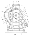
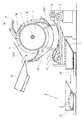
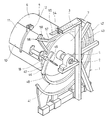
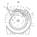
図1乃至図3のように、回転ドラム装置1は、横に長いベース台2の両端に対向して設けた支持枠3、3間の上部に回転ドラム4を回転自在となるよう水平に架設し、前記ベース台2に設けたモータの如き正逆切換えが可能な回転駆動機5で、前記回転ドラム4の正回転aと逆回転bおよび停止ができるようになっている。
As shown in FIGS. 1 to 3, the
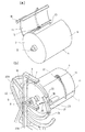
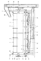
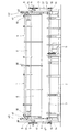
上記回転ドラム4は、横長となる円筒状の胴部6と、この胴部6の両端を閉鎖する端板7、7と、両端板7、7の外面に胴部6と同軸心状の配置で固定した軸8、8とで形成され、軸8、8が支持枠3、3の途中に軸受9、9を介して支持され、軸心が水平の状態で回転自在になっていると共に、前記胴部6には、開口幅が円周方向に略90°前後の範囲となり、長さ方向の全長にわたる横長の開口10が設けられ、この開口10が外開き式の蓋11によって開閉自在になっている。
The
上記の蓋11は、開口10を閉じた位置で胴部6の周壁の一部を構成するよう、胴部6と同様の曲率を有する弧状で、開口10の幅と長さを閉鎖し得る大きさを有し、胴部6の開口10に対して回転ドラム4の正回転方向の前方に位置する開口縁にヒンジの枢止軸12で後端部が取付けられ、蓋11は枢止軸12を中心に、胴部6の外側に重なって開口10を閉じる閉蓋位置から、胴部6の外方に向けて突出する開蓋位置の間を回動自在となり、図3(a)は蓋11が開口10を開いた開蓋位置の状態を示している。
The
なお、第1の実施の形態において、回転ドラム4の正回転aとは、図4乃至図6において反時計方向の回転であり、逆回転bとは同図時計方向の回転である。
In the first embodiment, the forward rotation a of the
上記胴部6及び蓋11の内面には、耐摩ライニングが施されていると共に、胴部6の内部には、図示省略したが、被処理物の種類や処理内容に対応した構造のかき上げ用の羽根が設けられている。
The inner surface of the
上記ベース台2に、回転ドラム4よりも下方に位置する水平の長い中間軸13が下部軸受14での支持によって回転可能に配置され、この中間軸13と回転駆動機5を連動すると共に、回転ドラム4の軸8、8に固定したスプロケット15と中間軸13の両端部に固定したスプロケット16をチェーン17等で連動している。
A horizontally long
従って、回転駆動機5を起動すると、中間軸13を介して回転ドラム4に回転が伝わり、回転駆動機5の制御により、回転ドラム4の正回転a、逆回転b、停止が行えることになる。
Accordingly, when the
上記蓋11の外面には、長さ方向の両端部で支点となる枢止軸12から離れた途中もしくは開閉動縁に近い先端位置に、回転ドラム4の端面よりも長さ方向の外方に突出する蓋開閉部材18が取付けられ、この蓋開閉部材18は円軸状のものでもよいが、図示の場合、回転ドラム4の長さ方向と平行する軸心を中心に回転自在となるよう取付けたベアリングのような転子を用いた例を示している。
On the outer surface of the
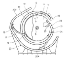
上記回転ドラム4の軸方向両端部の外側位置のそれぞれに、回転ドラム4の正回転時に蓋開閉部材18を介して蓋11を閉蓋状態に保持し、回転ドラム4の逆回転時に蓋開閉部材18の拘束を解いて開蓋を可能にする閉蓋保持レール19と、その半径方向外側に蓋開閉ガイド20が支持枠3、3への取付けによって配置されている。
The
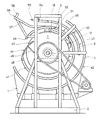
上記閉蓋保持レール19は、回転ドラム4を正回転aさせた時に、蓋11の閉じた状態を保持するように内周縁で蓋開閉部材18を誘導するよう内外周が同心円の環状に形成され、回転ドラム4と同軸心の配置となるよう支持枠3に固定されている。
The above-mentioned
この閉蓋保持レール19は、図4乃至図6のように、その内周径が回転ドラム4の外径よりも少し大径となり、蓋11が開口10を閉じた閉蓋状態でその内周縁に蓋開閉部材18が当接し、蓋開閉部材18を半径方向の外方に移動しないように拘束すると同時に内周縁に沿った回転は自在とし、蓋11が開口10を閉じた閉蓋状態を保持すると共に、閉蓋状態で回転ドラム4が正回転aすることができるようになっている。
As shown in FIGS. 4 to 6, the inner diameter of the
上記閉蓋保持レール19の途中で、回転ドラム4の正回転a時に蓋開閉部材18が下から上に向かって回動していく部分の途中となる、図2において右側である一方側部の位置に、回転ドラム4の正回転aと逆回転bの切換えによって、蓋11の蓋開閉部材18をこの閉蓋保持レール19の内側に入れて閉蓋状態にしたり、外側に出して開蓋状態にするための切換え部21が設けられている。
In the middle of the
即ち、上記切換え部21と蓋開閉部材18は、蓋開閉部材18が閉蓋保持レール19の内側に位置する閉蓋状態で、回転ドラム4を逆回転bさせたときに、蓋開閉部材18をこの閉蓋保持レール19の外側に誘導することで蓋11が開口10を開けるように作用し、また、蓋開閉部材18が閉蓋保持レール19の外側に位置する開蓋状態で、回転ドラム4を正回転aさせると、蓋開閉部材18を閉蓋保持レール19の内側に誘導して蓋11が開口10を閉じるように作用する。
That is, the switching
この切換え部21は、閉蓋保持レール19の途中で一方側部の位置に分断部22を周方向に沿って所定間隔となるように設け、この分断部22に切換えレール23を配置して形成されている。
The switching
上記切換えレール23は、上記分断部22に収まる長さを有し、分断部22における回転ドラム4の正回転a方向に対して後方となる下側端部に枢軸24で下端を枢止し、枢軸24を支点として閉蓋保持レール19の内側へ傾斜状に突出する開位置(図4参照)と、分断部22に納まって外側に開かないことで閉蓋保持レール19の連続する環状状態を保持する閉位置(図6参照)の間を揺動可能となり、この切換えレール23にスプリング25で常時開位置への復帰弾性が付勢されている。
The switching
なお、切換えレール23が開位置にあるとき、図5のように、切換えレール23の上部先端と閉蓋保持レール19の分断部22における上側端部との間には、蓋開閉部材18が通過できる隙間が形成されることになる。
When the switching
上記閉蓋保持レール19の内周縁で蓋開閉部材18が拘束されて蓋11が開口10を閉じた閉蓋状態で、回転ドラム4を正回転aさせると、閉蓋保持レール19の内周縁を回動する蓋開閉部材18は、切換えレール23の部分に対して、図6に示すように、切換えレール23を外方へ閉位置に押すようにして通過し、このため、切換えレール23は蓋開閉部材18が閉蓋保持レール19の半径方向外側に出るのを防ぎ、回転ドラム4が正回転aしているときは、蓋開閉部材18が閉蓋保持レール19の内周で外側に移動しないよう拘束され、開口10が蓋11で閉じられたままの閉蓋状態が維持される。
When the
また、上記閉蓋状態で回転ドラム4を逆回転bさせた場合、切換えレール23は内側に向けて通常開位置にあるので、蓋11が枢止軸12を後ろにして上部から下部に向けて回動してくると、蓋開閉部材18は内側に傾斜している切換えレール23の上端部外側に当接し、この切換えレール23で閉蓋保持レール19の外側に誘導されることになり、これにより、蓋開閉部材18は閉蓋保持レール19の拘束から解かれ、蓋11は回転ドラム4の逆回転bの進行と共に、枢止軸12を支点に自重で垂下することで開口10を開放することになる。
Further, when the
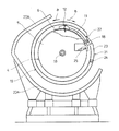
上記蓋開閉ガイド20は、閉蓋保持レール19の下半部における半径方向の外側に間隔を設けて位置し、閉蓋保持レール19と略同心円状となる開蓋保持部20aと、この開蓋保持部20aにおいて、回転ドラム4の逆回転bの方向の前方に位置する端部から連なり、斜め上向きに向かった後、閉蓋保持レール19の上部に向けて接近するように屈曲する閉蓋誘導部20bとで形成され、図4のように、下方に回動してきた蓋開閉部材18がその内周縁に当接し得るように支持枠3に固定されている。
The lid opening /
この蓋開閉ガイド20の開蓋保持部20aは、回転ドラム4を逆回転bさせたときに、蓋開閉部材18が切換えレール23の外側に誘導されて蓋11が自重で垂下状態となって下方に移動してくると、その内周縁で蓋開閉部材18を受け取り、蓋11が開口10を開いた開蓋状態を保持するように、蓋開閉部材18を逆回転bの方向に前記蓋11の枢止軸12よりも先行するように誘導し、図4のように、回転ドラム4を開口10が同図左側の側部に向く位相で停止させると、蓋開閉部材18は開蓋保持部20aの終端に達し、自重によって蓋11は少し上向きの水平に近い姿勢となって開口10を開いた状態に保持され、開口10から回転ドラム4内への被処理物の投入が可能となる。
The lid opening and holding
また、閉蓋誘導部20bは、上記した開口10が開放された開蓋状態から回転ドラム4が逆回転bすると、押上られていく蓋11の蓋開閉部材18を回転ドラム4の胴部6に接近するよう誘導し、上部に移動する開口10に向けて蓋11を倒し込むように起こしていき、蓋11は回転ドラム4の上部に移動すると重心の移動で自重によって倒れ込むので、蓋開閉部材18は閉蓋誘導部20bから離れ、上記閉蓋保持レール19の外周に当接して保持され、切換え部21に向けて移動することになる。
Further, the
なお、図示詳細を略したが、前記回転ドラム4の回転停止時に、回転ドラム4が惰性回転しないよう、例えば、回転ドラム4の端部に対して圧接可能なブレーキ手段を設けたり、回転ドラム4の軸8を利用して被処理物の処理時に回転ドラム4内に給水する給水手段を設けることができる。
Although illustration details are omitted, for example, a brake means that can be pressed against the end of the
図7と図8は、この発明の回転ドラム装置1で被処理物の付着物を除去するケレン処理を行う場合の、被処理物とケレン部材の分別及びケレン部材の回収再使用の方法を実施する手段を示している。
7 and 8 show a method of separating the object to be processed and the kelen member and collecting and reusing the element when using the
ここで、被処理物(ワーク)cが建設資材のような鍔付きの長尺パイプや突起部分が多いものでは、被処理物cだけを回転ドラム4内に投入し、回転ドラム4を正回転させてケレンを行うと、突起部分が被処理物cに当たってダメージを与えると同時に、突起部分が邪魔になって全体的に均一なケレン処理ができないことになり、このため、被処理物cとこれよりも小径の鋼球等のケレン部材dを回転ドラム4内へ同時に多数投入してケレンを行うと、被処理物cに与えるダメージを少なくし、隅々まで綺麗にケレンすることができる。
Here, when the object to be processed (work) c is a long pipe with a hook or many protrusions such as construction materials, only the object to be processed c is put into the
しかし、被処理物cとケレン部材dを混合してケレン処理すると、回転ドラム4内からの取出し後に被処理物cとケレン部材dを分別するための作業が必要になってくると共に、ケレン部材dは効率的に再使用できるように工夫しなければならない。
However, when the object to be processed c and the kelen member d are mixed and subjected to the kelen process, an operation for separating the object to be processed c and the kelen member d after the take-out from the
図7は、被処理物cとケレン部材dの分別とケレン部材の効率的な再使用方法の第1の例を示し、回転ドラム4の下部に、スキッドやスノコのような篩分け部材31を設置し、この篩分け部材31の下部にケレン部材dの回収容器32を配置している。
FIG. 7 shows a first example of separation of the workpiece c and the kelen member d and an efficient reuse method of the kelen member. A sieving
上記篩分け部材31のスキッドやスノコは、被処理物cが通過できず、これよりも小さいケレン部材dだけが通過できるように孔や網目の形状や大きさが設定され、回転ドラム4の開口10から排出された被処理物cとケレン部材dの混合物を篩分け部材31で受取り、振動等を与えることにより、被処理物cを上面に残し、ケレン部材dを落下させる。
The shape and size of holes and meshes are set so that the skid and slat of the sieving
篩分け部材31上の被処理物cは、人為的又は機械的な手段で取り除き、落下したケレン部材dは、直下に待機する回収容器32内に収納し、この回収容器32をフォークリフト33等でハンドリングして引き出し、図7に一点鎖線から二点鎖線で示すようにこれを持ち上げ、開口10が開放する開蓋状態で停止させた回転ドラム4内に開口10からケレン部材を投入するようにしたものである。
The object c to be processed on the sieving
図8は、被処理物とケレン部材の分別とケレン部材の効率的な再使用方法の第2の例を示し、回転ドラム4の直下の位置に、長さ方向の中央に向けて下がり傾斜となる受取りバケット34を配置し、この受取りバケット34の上面に上述した第1の例と同様の篩分け部材31を設け、受取りバケット34の中央下部の位置に底面が一方に下がり傾斜となる回収容器35を設置し、回転ドラム4の一方端部の位置に縦型コンベア36を配置し、前記回収容器35の下がり側端部と縦型コンベア36の下部を傾斜通路37で接続している。
FIG. 8 shows a second example of the separation of the workpiece and the kelen member and an efficient method of reuse of the kelen member, and a downward slope toward the center in the length direction at a position directly below the
回収容器35内に回収した鋼球のようなケレン部材dは、回収容器35から傾斜通路37を転がって縦型コンベア36の下部に転入し、この縦型コンベア36で持ち上げられ、上端のシュート38を介して、開口10が開放する状態で停止させた回転ドラム4内に開口10からケレン部材を投入するようにしたものであり、篩分け部材31の上に残った被処理物cは、人為的又は機械的な手段で取り出せばよい。
The kelen member d such as a steel ball collected in the
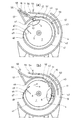
この発明の第1の実施の形態の回転ドラム装置1は、上記のような構成であり、図4は回転ドラム4の開口10を開いて内部に被処理物やケレン部材を投入する状態を示し、閉蓋保持レール19の外側に蓋開閉部材18が位置する状態で、回転ドラム4を開口10が同図の左側で切換え部21と反対側に位置するよう停止させると、開口10の下側に枢止軸12が位置する蓋11は自重で外側に開き、その蓋開閉部材18が蓋開閉ガイド20における開蓋保持部20aの終端で閉蓋誘導部20bとの屈曲状となる境界部分に位置して保持され、開口10から回転ドラム4内に被処理物やケレン部材の投入が可能となる。
The
被処理物やケレン部材の投入後に、回転ドラム4を図4の矢印で示した時計方向に低速で逆回転bさせると、枢止軸12によって蓋11が押上られ、枢止軸12よりも先行して回動する蓋開閉部材18が閉蓋誘導部20bで回転ドラム4に接近するよう誘導され、これにより、蓋11は逆回転bの進行と共に開口10に向けて起こされ、枢止軸12と蓋開閉部材18を結ぶ線が垂直線を通過すると、重心の移動によって蓋11は胴部6に向けて自重で倒れ込み、図4に一点鎖線で示すように、蓋開閉部材18が閉蓋保持レール19の外周縁に当接し、蓋11は開口10を少し開いた状態で逆回転bの方向に回動していく。
When the
なお、図7で示したように、蓋11の途中と胴部6との間をショックアブソーバー39で連結し、蓋11が自重で倒れ込んだときの衝撃発生を防ぐようにすることができる。
As shown in FIG. 7, the middle of the
逆回転bさせた回転ドラム4の開口10が図5の斜め右上の位置に回動してくると、蓋開閉部材18は閉蓋保持レール19の分断部22に臨み、蓋11は自重で垂れ下がることで開口10に接近し、図5のように、蓋開閉部材18が開位置にある切換えレール23の外側に当接する状態で回転ドラム4の逆回転bを停止させる。
When the
次に、図5の状態から回転ドラム4を正回転aさせると、蓋11が自重で開口10を閉じるように胴部6に向けて接近しようとすることで、蓋開閉部材18は切換えレール23の外側に沿って移動し、開位置にある切換えレール23と閉蓋保持レール19の分断部22の上端との間に形成された間隔から閉蓋保持レール19の内部に向けて進入すると、蓋11は開口10を閉じた閉蓋状態となる。
Next, when the
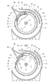
蓋開閉部材18が閉蓋保持レール19の内部に進入すると、蓋開閉部材18が閉蓋保持レール19の内周縁に当接することによって半径方向の外方への移動が拘束され、これにより、蓋11の開口10を閉じた閉蓋状態を保持し、この後、回転ドラム4を連続的に高速で正回転aさせることにより、被処理物に対してケレン等の処理を施すことができる。
When the lid opening / closing
上記閉蓋保持レール19の分断部22に設けた切換えレール23は、スプリング25の引圧で、回転ドラム4の正回転aの方向の前方に位置する上端側が閉蓋保持レール19の内側に突出する傾斜状の開状態になっており、このため、回転ドラム4の連続的な正回転aのときにおいて、蓋開閉部材18が切換えレール23の部分を通過するとき、図6のように、蓋開閉部材18は切換えレール23を閉じ位置に押すことによって通過し、蓋開閉部材18が通過すると切換えレール23は開位置に戻ることになり、回転ドラム4の連続的な正回転aのときはこのような動作を繰り返し行うことになる。
The switching
次に、ケレンの処理後に被処理物を回転ドラム4内から取り出すには、回転ドラム4を低速の逆回転bに切換え、蓋11が上部に位置する状態から逆回転bすると、蓋開閉部材18は開位置にある切換えレール23に当接してその外側に誘導され、閉蓋保持レール19の拘束から蓋開閉部材18が解かれると、下方に向けて回動する開口10に対して回動方向の後方に枢止されている蓋11は自重で垂下することで開口10を開き、開かれた開口10が下方に移動する位置で回転ドラム4を停止させ、回転ドラム4の内部の被処理物を開いた開口10から自重によって落下排出させる。
Next, in order to take out the object to be processed from the
このとき、蓋11の蓋開閉部材18は、図4に二点鎖線で示したように、胴部6から蓋11が自重で垂れ下がりながら逆回転bの方向に回動することで蓋開閉ガイド20の開蓋保持部20aに当接し、この開蓋保持部20aの内周で蓋開閉部材18を逆回転bの方向に誘導することで、蓋11は開口10を開いた姿勢が保持される。
At this time, as shown by a two-dot chain line in FIG. 4, the lid opening / closing
被処理物の排出後、回転ドラム4を逆回転bの方向に回動させ、図4に実線で示したように、開口10が同図左側に向く位置で停止させ、開口10から新たな被処理物の投入に備えるようにする。
After discharging the object to be processed, the
次に、図9乃至図15は、この発明の回転ドラム装置の第2の実施形態を示している。なお、上記した第1の実施形態と同一部分には同一符号を付して説明に代える。 Next, FIGS. 9 to 15 show a second embodiment of the rotary drum device of the present invention. The same parts as those in the first embodiment described above are denoted by the same reference numerals and are not described.
この第2の実施形態の回転ドラム装置1は、回転ドラムの両端に閉蓋保持レールを配置し、この閉蓋保持レールの途中で二箇所の位置に、開蓋用の切換え部と閉蓋用の切換え部を設け、回転ドラムの正逆回転の切換えとによって、回転ドラムに設けた開口を自動的に開閉することができるようにしたものである。
In the
図9乃至図11のように、回転ドラム4の軸方向両端部の外側位置のそれぞれに、回転ドラム4の正回転時に蓋開閉部材18を介して蓋11を閉蓋状態に保持し、回転ドラム4の逆回転時に蓋開閉部材18の拘束を解いて開蓋を可能にする閉蓋保持レール41と、その半径方向外側に蓋開閉ガイド42と、前記閉蓋保持レール41と蓋開閉ガイド42の間に位置する開蓋保持ガイド43が配置されている。
As shown in FIGS. 9 to 11, the
なお、この第2の実施形態において、回転ドラム4の正回転aは図12乃至図15において時計方向、逆回転bは同反時計方向になっている。
In the second embodiment, the forward rotation a of the
上記閉蓋保持レール41は、内外径が回転ドラム4と同軸心の環状となり、閉じた状態にある蓋11の蓋開閉部材18を半径方向の外方に移動しないよう拘束しつつ回転方向に誘導する内径を有し、その途中で図10の左側となる一方側方の位置に開蓋用の第1の切換え部44と、他方側方で上部の位置に閉蓋用の第2の切換え部45が設けられている。
The
開蓋用の第1の切換え部44は、閉蓋状態にある回転ドラム4の逆回転時に蓋11を開くためのものであり、第1の実施形態の切換え部21と同様の構造を有し、閉蓋保持レール41の分断部46を開閉するように設けた切換えレール47が回転ドラム4の正回転方向の後方である枢軸48を支点とし、スプリング49で常時内側に傾斜する開位置に保持され、閉位置では閉蓋保持レール41を連続状とするようになっている。
The
閉蓋用の第2の切換え部45は、開蓋状態にある回転ドラム4の正回転時に蓋11を閉じるためのものであり、閉蓋保持レール41の分断部50を開閉するように設けた切換えレール51が回転ドラム4の正回転方向の後方に位置する枢軸52を支点とし、スプリング53で常時分断部50を閉鎖して閉蓋保持レール41を連続状とする閉位置に保持され、この閉位置から外側には開かず内側に傾斜することができるようになっている。
The
この閉蓋用の第2の切換え部45の切換えレール51を閉じ位置に保持するスプリング53の弾性は、切換えレール51の外側に蓋開閉部材18が載って蓋11の重量が加わったときに、切換えレール51が内側への傾斜となる開位置に移動するように設定されている。
The elasticity of the
上記蓋開閉ガイド42は、閉蓋保持レール41の外側に対して、図10の左側下部の位置から下部を通って右側上部の位置に達する範囲の長さを有する欠円弧状で、閉蓋保持レール41の半径方向の外側に所定の間隔を設けて同心円状となる配置となり、図14のように、回転ドラム4の逆転によって、閉蓋保持レール41の外側を下方に回動してきた蓋開閉部材18がその内周縁に当接し得るように支持枠3に固定されている。
The lid opening /
上記開蓋保持ガイド43は、閉蓋保持レール41と蓋開閉ガイド42の中間に位置する円弧状となり、先端が図10の右側で軸8と同一水平線上に位置し、後端が回転ドラム4の軸心直上に位置する間の90°の範囲に外周が回転ドラム4と同軸心となるよう設けられ、回転ドラム4の逆回転時に開蓋した蓋11の蓋開閉部材18を外周で誘導するようになっている。
The lid
この開蓋保持ガイド43の回転ドラム4の逆回転方向の前方に位置する後端に、スプリング54で開蓋保持ガイド43の延長となる水平状態に保持され、蓋開閉部材18が載って蓋11の重量が加わってときに、閉蓋保持レール41に向けて傾斜可能となり、開蓋保持ガイド43に沿って移動してきた蓋開閉部材18を閉蓋保持レール43の外周に向けて誘導するための傾動ガイド55が設けられている。
At the rear end of the
上記閉蓋保持レール41の上部外側で、傾動ガイド55に対して回転ドラム4の逆回転方向前方の位置からこの傾動ガイド55の下部の位置に、傾動ガイド55から受取った蓋開閉部材18を回転ドラム4の逆回転方向に移動しないように規制することで回転ドラム4を開口10が一定の向きになるよう停止させ、また、回転ドラム4の正回転によって蓋開閉部材18を閉蓋保持レール41の外周に誘導するストッパー部56が設けられている。
The lid opening / closing
このストッパー部56は、閉蓋保持レール41の上部外側から回転ドラム4の逆回転方向に延びて斜め上方向に向く誘導レール57の先端部にストッパー片58を設けて形成され、回転ドラム4の逆回転により蓋開閉部材18が開蓋保持ガイド43の外側から前記誘導レール57に載り移ってストッパー片58に当接する状態で回転ドラム4を止めれば、開口10が図10の左側に向くよう常に一定の位置に停止させることができる。
This
この発明の第2の実施の形態の回転ドラム装置1は、上記のような構成であり、図12乃至図15を主体に用いてケレン作業の工程を説明する。
The
図12(a)は回転ドラム4の開口10を開いて内部に被処理物やケレン部材を投入する初期の状態を示し、蓋開閉部材18が誘導レール57のストッパー片58に当接することで、回転ドラム4に対して蓋11は引上げられて開き位置に保持され、回転ドラム4は開放した開口10が同図の左側に向く位置に停止している。
FIG. 12A shows an initial state in which the
回転ドラム4内に対して開口10から被処理物やケレン部材の投入後に、回転ドラム4を図12(b)の矢印で示した時計方向に低速で正回転aさせると、枢止軸12を介して引かれることにより一体に回動する蓋11の蓋開閉部材18は、誘導レール57に沿って移動しながら回転ドラム4に接近するよう閉蓋保持レール41の上部に誘導され、図12(b)のように、更に正回転が続いて蓋開閉部材18が閉蓋用の第2の切換え部45の切換えレール51上に載ると、蓋11の開口10を閉じる方向の重量が加わることで切換えレール51は内側に押されて開位置に移動し、閉蓋保持レール41は閉蓋用の第2の切換え部45で分断された状態になる。
When the object to be processed and the kelen member are introduced into the
上記閉蓋用の第2の切換え部45は、回転ドラム4の軸8を通る水平線よりも高い位置に設定されているので、この閉蓋用の第2の切換え部45に接近してくる蓋11は、枢止軸12を支点として自重により開口10を閉鎖せんとする位相にあり、このため、蓋開閉部材18は、切換えレール51の外周に沿って移動することで閉蓋用の第2の切換え部45の分断部50から閉蓋保持レール41の内側に誘導されることになり、蓋11は自重によって開口10を閉じた閉蓋状態となる。
Since the
図13(c)のように、閉蓋用の第2の切換え部45の切換えレール51は、蓋開閉部材18が通過すると閉位置に戻り、蓋開閉部材18が閉蓋保持レール41の内周縁に当接することによって半径方向の外方への移動が拘束され、これにより、蓋11の開口10を閉じた閉蓋状態を保持し、この後、回転ドラム4を連続的に高速で正回転aさせることにより、被処理物に対してケレン等の処理を施すことができる。
As shown in FIG. 13C, the switching
上記回転ドラム4の高速正回転a時に、閉蓋保持レール41の内周を回動する蓋開閉部材18は、開蓋用の第1の切換え部44と閉蓋用の第2の切換え部45を交互に通過することになるが、閉蓋用の第2の切換え部45においては、切換えレール51が閉位置にあって閉蓋保持レール41を連続状にしているので、この閉蓋用の第2の切換え部45を作動させることなく蓋開閉部材18は回動する。
The lid opening / closing
開蓋用の第1の切換え部44においては、切換えレール47がスプリング49の引圧で、回転ドラム4の正回転aの方向の前方に位置する上端側が閉蓋保持レール41の内側に突出する傾斜状の開状態になっており、このため、回転ドラム4の連続的な正回転aのときにおいて、蓋開閉部材18が切換えレール47の部分を通過するとき、図13(c)のように、蓋開閉部材18は切換えレール47を閉じ位置に押すことによって通過し、蓋開閉部材18が通過すると切換えレール47は開位置に戻ることになり、回転ドラム4の連続的な正回転aのときはこのような動作を繰り返し行うことになる。
In the
次に、ケレンの処理後に被処理物を回転ドラム4内から取り出すには、回転ドラム4を低速の逆回転bに切換え、蓋11が回転ドラム4の上部に位置する状態から逆回転bすると、図13(d)のように、蓋開閉部材18は開蓋用の第1の切換え部44における開位置にある切換えレール47に当接してその外側に誘導され、蓋開閉部材18が閉蓋保持レール41の拘束から解かれると、下方に向けて回動する開口10に対して回動方向の後方に枢止されている蓋11は自重で垂下することで開口10を開き、開かれた開口10が下方に移動する位置で回転ドラム4を停止させ、回転ドラム4の内部の被処理物を開いた開口10から自重によって落下排出させる。
Next, in order to take out the object to be processed from the
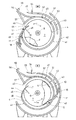
このとき、蓋11の蓋開閉部材18は、図14(e)に示したように、胴部6から蓋11が自重で垂れ下がりながら逆回転bの方向に回動することで蓋開閉ガイド42の内周に当接し、内周で蓋開閉部材18を逆回転bの方向に誘導することで、蓋11は開口10を開いた姿勢が保持される。
At this time, as shown in FIG. 14 (e), the lid opening / closing
被処理物の排出後、回転ドラム4を逆回転bの方向に回動させると、図14(f)のように、蓋開閉ガイド42の内周に当接する蓋開閉部材18は、押上られる蓋11を一定角度の開状態に保持し、上昇していく蓋開閉部材18は、蓋開閉ガイド42とその内側に位置する開蓋保持ガイド43の間に進入し、蓋11の枢止軸12が軸8を通る水平線よりも上方に通過すると、蓋開閉ガイド42の上端側で蓋開閉部材18が回転ドラム4に接近するように押し込まれ、蓋11は枢止軸12を支点に起立姿勢となり、蓋11の重心が枢止軸12を通る垂直軸心から回転ドラム4側に移動した時点で回転ドラム4側に向けて倒れ込み、この倒れ込み途中で蓋開閉部材18は開蓋保持ガイド43の外周に載り、蓋11は開口10を完全に閉じないように倒れ込んだ状態に保持される。
When the
回転ドラム4の逆回転bが続き、図15(g)のように、蓋開閉部材18が傾動ガイド55の上に載ると、蓋11の重量が加わった傾動ガイド55が下方に傾斜し、下方に位置する誘導レール57上に誘導され、この誘導レール57の先端側に移動することでストッパー片58に当接し、この状態で回転ドラム4の逆回転を停止させる。
When the reverse rotation b of the
このように、蓋開閉部材18がストッパー片58に当接した状態で回転ドラム4を停止させると、回転ドラム4の開口10は常に横向きの定位置になるよう図12(a)の初期状態に戻って停止させることができ、蓋11は開口10の上部に跳ね上げられた開位置に保持されているので、全開した開口10から新たな被処理物を投入することができ、開口10の開状態での停止位置精度が向上し、被処理物を投入作業に有利となる。
As described above, when the
また、この第2の実施の形態の回転ドラム装置1は、閉蓋保持レール41に閉蓋用の第2の切換え部45を設けることにより、開蓋状態で停止する回転ドラム4を閉蓋状態にする場合、回転ドラム4を連続的に正回転aさせるだけで閉蓋状態に移行することになり、第1の実施の形態の回転ドラム装置1のように、逆回転と停止、正回転への切換えに比べて回転ドラム4の制御が簡素化できるという利点がある。
In addition, the
上記のように、第1及び第2の実施の形態で示したこの発明の回転ドラム装置1は、回転ドラム4を回転駆動機5で直接回転駆動し、回転ドラム4の回転を正回転aと逆回転bに切換えることで、回転ドラム4の胴部6に設けた開口10を蓋11によって自動的に開閉することができ、蓋11の両端部に蓋開閉部材18を取付け、回転ドラム4の両端部位置に、閉蓋保持レール19、41と蓋開閉ガイド20、42又はこれに加えて開蓋保持ガイド43を配置するだけでよいので、全体の構造が簡略化できるだけでなく、耐久性に優れたものとなる。
As described above, in the
1 回転ドラム装置
2 ベース台
3 支持枠
4 回転ドラム
5 回転駆動機
6 胴部
7 端板
8 軸
9 軸受
10 開口
11 蓋
12 枢止軸
13 中間軸
14 下部軸受
15 スプロケット
16 スプロケット
17 チェーン
18 蓋開閉部材
19 閉蓋保持レール
20 蓋開閉ガイド
20a 開蓋保持部
20b 閉蓋誘導部
21 切換え部
22 分断部
23 切換えレール
24 枢軸
25 スプリング
31 篩分け部材
32 回収容器
33 フォークリフト
34 受取りバケット
35 回収容器
36 縦型コンベア
37 傾斜通路
38 シュート
39 ショックアブソーバー
41 閉蓋保持レール
42 蓋開閉ガイド
43 開蓋保持ガイド
44 開蓋用の第1の切換え部
45 閉蓋用の第2の切換え部
46 分断部
47 切換えレール
48 枢軸
49 スプリング
50 分断部
51 切換えレール
52 枢軸
53 スプリング
54 スプリング
55 傾動ガイド
56 ストッパー部
57 誘導レール
58 ストッパー片
a 正回転
b 逆回転
c 被処理物
d ケレン部材
DESCRIPTION OF
Claims (5)
前記回転ドラムの軸方向端面よりも外側位置に、回転ドラムと同軸心の配置となり、閉じた状態にある蓋の蓋開閉部材を半径方向の外方に移動しないよう拘束しつつ回転方向に誘導する内径を有し、回転ドラムを蓋の閉じた状態で正回転させたとき、蓋の閉じた状態を保持する環状の閉蓋保持レールを配置し、
前記閉蓋保持レールの途中位置に、回転ドラムの正回転と逆回転の切換えにより、移動する前記蓋開閉部材を閉蓋保持レールの内側又は外側に誘導し、蓋を閉じた状態と開いた状態の何れかに変化させるための切換え部を設けた回転ドラム装置。 A rotating drum is rotatably supported through a shaft on the axis so as to rotate in the forward and reverse directions, and on the side edge of the opening provided in the body portion of the rotating drum with respect to the forward rotating direction of the rotating drum. An outer opening type lid that opens and closes the opening is pivotally mounted with an end located at the front as a fulcrum, and a lid opening and closing member is attached at a position away from the fulcrum of the lid,
Arranged coaxially with the rotating drum at a position outside the axial end surface of the rotating drum, the lid opening / closing member of the closed lid is guided in the rotating direction while restraining it from moving radially outward. An annular lid holding rail that has an inner diameter and holds the lid closed when the rotating drum is rotated forward with the lid closed,
The lid opening / closing member is guided to the inside or outside of the lid holding rail by switching between forward rotation and reverse rotation of the rotary drum at an intermediate position of the lid holding rail, and the lid is closed and opened. A rotary drum device provided with a switching unit for changing to any of the above.
前記切換えレールが、回転ドラムの正回転方向に対して後方に位置する端部を支点にして、閉蓋保持レールの内側に傾斜する開位置と、閉蓋保持レールの連続する環状状態を保持する閉位置の間を揺動可能となり、この切換えレールに常時開位置への復帰弾性を付勢した請求項1に記載の回転ドラム装置。 The switching portion provided in the middle of the lid holding rail is provided with a dividing portion in the middle of the closing lid holding rail, and a switching rail capable of holding the continuous annular state of the lid holding rail is provided in the dividing portion. Arranged and formed
The switching rail holds an open position inclined to the inside of the lid holding rail and a continuous annular state of the lid holding rail, with an end portion located rearward with respect to the positive rotation direction of the rotating drum as a fulcrum. 2. The rotating drum device according to claim 1, wherein the rotating drum device can swing between the closed positions, and the switching rail is urged to return elastically to the normally open position.
前記回転ドラムの軸方向端面よりも外側位置に、回転ドラムと同軸心の配置となり、閉じた状態にある蓋の蓋開閉部材を半径方向の外方に移動しないよう拘束しつつ回転方向に誘導する内径を有し、回転ドラムを蓋の閉じた状態で正回転させたとき、蓋の閉じた状態を保持する環状の閉蓋保持レールを配置し、
前記閉蓋保持レールの途中位置に、回転ドラムの逆回転時に、閉蓋保持レールの内側に位置する蓋開閉部材を閉蓋保持レールの外側に誘導する開蓋用の第1の切換え部と、回転ドラムの正回転時に、閉蓋保持レールの外側に位置する蓋開閉部材を閉蓋保持レールの内側に誘導する閉蓋用の第2の切換え部を設け、回転ドラムの正回転と逆回転の切換えにより、蓋を閉じた状態と開いた状態の何れかに変化させるようにした回転ドラム装置。 A rotating drum is rotatably supported through a shaft on the axis so as to rotate in the forward and reverse directions, and on the side edge of the opening provided in the body portion of the rotating drum with respect to the forward rotating direction of the rotating drum. An outer opening type lid that opens and closes the opening is pivotally mounted with an end located at the front as a fulcrum, and a lid opening and closing member is attached at a position away from the fulcrum of the lid,
Arranged coaxially with the rotating drum at a position outside the axial end surface of the rotating drum, the lid opening / closing member of the closed lid is guided in the rotating direction while restraining it from moving radially outward. An annular lid holding rail that has an inner diameter and holds the lid closed when the rotating drum is rotated forward with the lid closed,
A first switching portion for opening the lid, which guides a lid opening / closing member located inside the lid holding rail to the outside of the lid holding rail when the rotary drum rotates in the reverse direction at the middle of the lid holding rail; A second switching unit for closing the lid that opens and closes the lid opening / closing member located outside the lid holding rail when the rotary drum rotates forward is provided. A rotating drum device that changes between a closed state and an open state by switching.
上記閉蓋用の第2の切換え部は、前記閉蓋保持レールの途中に分断部を設け、この分断部に、閉蓋保持レールの連続する環状状態を保持することのできる切換えレールを配置し、この切換えレールが、回転ドラムの正回転方向に対して後方に位置する端部を支点にして、閉蓋保持レールの内側に傾斜する開位置と、閉蓋保持レールの連続する環状状態を保持する閉位置の間を揺動可能となり、この切換えレールに常時閉位置への復帰弾性を付勢して形成されている請求項3に記載の回転ドラム装置。 The first switching portion for opening the lid provided in the middle of the lid holding rail is provided with a dividing portion in the middle of the lid holding rail, and this dividing portion holds a continuous annular state of the lid holding rail. A switching rail that can be operated, and the switching rail tilts inwardly of the lid holding rail with the end located rearward with respect to the forward rotation direction of the rotating drum as a fulcrum, and the lid It becomes possible to swing between the closed positions that hold the continuous annular state of the holding rail, and is formed by energizing the return elasticity to the normally open position on this switching rail,
The second switching portion for closing the lid is provided with a dividing portion in the middle of the closing lid holding rail, and a switching rail capable of holding the continuous annular state of the closing lid holding rail is disposed in the dividing portion. This switching rail maintains the open position that inclines inside the lid holding rail and the continuous annular state of the lid holding rail, with the end located rearward with respect to the normal rotation direction of the rotating drum as a fulcrum. 4. The rotary drum device according to claim 3, wherein the rotary drum device is swingable between the closed positions, and the switching rail is formed by urging the return elasticity to the normally closed position.
Priority Applications (1)
| Application Number | Priority Date | Filing Date | Title |
|---|---|---|---|
| JP2010268301A JP5587754B2 (en) | 2010-06-21 | 2010-12-01 | Rotating drum device |
Applications Claiming Priority (3)
| Application Number | Priority Date | Filing Date | Title |
|---|---|---|---|
| JP2010140499 | 2010-06-21 | ||
| JP2010140499 | 2010-06-21 | ||
| JP2010268301A JP5587754B2 (en) | 2010-06-21 | 2010-12-01 | Rotating drum device |
Publications (3)
| Publication Number | Publication Date |
|---|---|
| JP2012024915A true JP2012024915A (en) | 2012-02-09 |
| JP2012024915A5 JP2012024915A5 (en) | 2013-10-10 |
| JP5587754B2 JP5587754B2 (en) | 2014-09-10 |
Family
ID=45778477
Family Applications (1)
| Application Number | Title | Priority Date | Filing Date |
|---|---|---|---|
| JP2010268301A Expired - Fee Related JP5587754B2 (en) | 2010-06-21 | 2010-12-01 | Rotating drum device |
Country Status (1)
| Country | Link |
|---|---|
| JP (1) | JP5587754B2 (en) |
Cited By (8)
| Publication number | Priority date | Publication date | Assignee | Title |
|---|---|---|---|---|
| JP2015047093A (en) * | 2013-08-30 | 2015-03-16 | 株式会社クボタ | Food mixing machine |
| CN104413346A (en) * | 2013-08-30 | 2015-03-18 | 株式会社久保田 | Food material mixing machine |
| JP2015053933A (en) * | 2013-09-13 | 2015-03-23 | 株式会社クボタ | Food mixing machine |
| CN104476377A (en) * | 2014-11-10 | 2015-04-01 | 胡健 | Recycling type dry type polishing equipment |
| CN106694313A (en) * | 2017-03-09 | 2017-05-24 | 贾建胜 | Convenient sealing ring lubricating device for producing household water filter |
| KR102447584B1 (en) * | 2022-06-07 | 2022-09-27 | 김태훈 | Cleaning device for tumbler lid with improved user convenience |
| CN117960489A (en) * | 2024-03-28 | 2024-05-03 | 大同宇林德石墨新材料股份有限公司 | Impregnating device for graphite electrode production |
| CN119771679A (en) * | 2024-12-23 | 2025-04-08 | 北京长城航空测控技术研究所有限公司 | Self-adaptive painting device for blade tenons and painting method thereof |
Citations (10)
| Publication number | Priority date | Publication date | Assignee | Title |
|---|---|---|---|---|
| US3283944A (en) * | 1962-06-20 | 1966-11-08 | Richardson Engineering Birming | Barrel apparatus |
| JPS57111871U (en) * | 1980-12-25 | 1982-07-10 | ||
| JPS6092768U (en) * | 1983-11-29 | 1985-06-25 | 日産自動車株式会社 | Internal combustion engine fuel injection nozzle |
| JPS6093768U (en) * | 1983-11-29 | 1985-06-26 | 中村 吉人 | barrel door opener |
| JPH01184059A (en) * | 1988-01-18 | 1989-07-21 | Tokai Rubber Ind Ltd | Barrel device with mechanism for automatically opening and closing lid |
| JPH0248166A (en) * | 1988-08-08 | 1990-02-16 | Yukio Okano | Barrel type processing equipment |
| US4918660A (en) * | 1987-04-14 | 1990-04-17 | Yvan Perrot | Industrial treatment machines with rotating vessel |
| US5071023A (en) * | 1989-09-08 | 1991-12-10 | Societe Nouvelle Clera | Device for manually opening and closing a vessel door |
| JPH10280684A (en) * | 1997-04-01 | 1998-10-20 | Taiyuu Kk | Rotary drum device |
| JPH11333391A (en) * | 1998-05-27 | 1999-12-07 | Daiyu Kk | Rotary drum device |
-
2010
- 2010-12-01 JP JP2010268301A patent/JP5587754B2/en not_active Expired - Fee Related
Patent Citations (10)
| Publication number | Priority date | Publication date | Assignee | Title |
|---|---|---|---|---|
| US3283944A (en) * | 1962-06-20 | 1966-11-08 | Richardson Engineering Birming | Barrel apparatus |
| JPS57111871U (en) * | 1980-12-25 | 1982-07-10 | ||
| JPS6092768U (en) * | 1983-11-29 | 1985-06-25 | 日産自動車株式会社 | Internal combustion engine fuel injection nozzle |
| JPS6093768U (en) * | 1983-11-29 | 1985-06-26 | 中村 吉人 | barrel door opener |
| US4918660A (en) * | 1987-04-14 | 1990-04-17 | Yvan Perrot | Industrial treatment machines with rotating vessel |
| JPH01184059A (en) * | 1988-01-18 | 1989-07-21 | Tokai Rubber Ind Ltd | Barrel device with mechanism for automatically opening and closing lid |
| JPH0248166A (en) * | 1988-08-08 | 1990-02-16 | Yukio Okano | Barrel type processing equipment |
| US5071023A (en) * | 1989-09-08 | 1991-12-10 | Societe Nouvelle Clera | Device for manually opening and closing a vessel door |
| JPH10280684A (en) * | 1997-04-01 | 1998-10-20 | Taiyuu Kk | Rotary drum device |
| JPH11333391A (en) * | 1998-05-27 | 1999-12-07 | Daiyu Kk | Rotary drum device |
Cited By (10)
| Publication number | Priority date | Publication date | Assignee | Title |
|---|---|---|---|---|
| JP2015047093A (en) * | 2013-08-30 | 2015-03-16 | 株式会社クボタ | Food mixing machine |
| CN104413346A (en) * | 2013-08-30 | 2015-03-18 | 株式会社久保田 | Food material mixing machine |
| CN104413346B (en) * | 2013-08-30 | 2018-02-16 | 株式会社久保田 | Food materials mixer |
| JP2015053933A (en) * | 2013-09-13 | 2015-03-23 | 株式会社クボタ | Food mixing machine |
| CN104476377A (en) * | 2014-11-10 | 2015-04-01 | 胡健 | Recycling type dry type polishing equipment |
| CN106694313A (en) * | 2017-03-09 | 2017-05-24 | 贾建胜 | Convenient sealing ring lubricating device for producing household water filter |
| KR102447584B1 (en) * | 2022-06-07 | 2022-09-27 | 김태훈 | Cleaning device for tumbler lid with improved user convenience |
| CN117960489A (en) * | 2024-03-28 | 2024-05-03 | 大同宇林德石墨新材料股份有限公司 | Impregnating device for graphite electrode production |
| CN117960489B (en) * | 2024-03-28 | 2024-07-05 | 大同宇林德石墨新材料股份有限公司 | Impregnating device for graphite electrode production |
| CN119771679A (en) * | 2024-12-23 | 2025-04-08 | 北京长城航空测控技术研究所有限公司 | Self-adaptive painting device for blade tenons and painting method thereof |
Also Published As
| Publication number | Publication date |
|---|---|
| JP5587754B2 (en) | 2014-09-10 |
Similar Documents
| Publication | Publication Date | Title |
|---|---|---|
| JP5587754B2 (en) | Rotating drum device | |
| KR101521425B1 (en) | Disposable Cup Automatic Separating Apparatus and Trash Automatic Recycling Apparatus Having the Same | |
| CN110743699A (en) | Discharge hopper of ore washer | |
| JP5912733B2 (en) | Mahjong tile automatic cleaning device | |
| CN1128310A (en) | Top loading horizontal axis automatic washer | |
| US5269440A (en) | Vibratory bowl feeder with automatic clean out function | |
| JPWO2014024572A1 (en) | Shot processing device | |
| CN112027610B (en) | Automatic yarn barrel feeding device | |
| KR20170037992A (en) | Shot processing apparatus | |
| JP5792595B2 (en) | Cap sorting device | |
| KR101424455B1 (en) | Apparatus for removing transportation article in tripper car | |
| AU645289B2 (en) | Modified plastic bag opening apparatus | |
| CN118992591B (en) | A feeding device | |
| JP2011240310A (en) | Trommel sorter | |
| JP5321621B2 (en) | Automatic full surface cleaning equipment | |
| US4230217A (en) | Bottle aligning machine | |
| JP2020059566A (en) | Case reversing device | |
| CN104986554A (en) | Automatic discharging device for food | |
| CN209411122U (en) | A kind of arranging machine | |
| CA2472389A1 (en) | Separation device | |
| CN213677556U (en) | Device for recycling storage box | |
| CN111184232B (en) | Automatic impurity removal production line for preventing garlic from sinking to bottom | |
| JP3105170B2 (en) | Bag breaking device | |
| JP2009046852A (en) | Drum type scraping device | |
| KR102435810B1 (en) | egg transfer device |
Legal Events
| Date | Code | Title | Description |
|---|---|---|---|
| A521 | Request for written amendment filed |
Free format text: JAPANESE INTERMEDIATE CODE: A523 Effective date: 20130826 |
|
| A621 | Written request for application examination |
Free format text: JAPANESE INTERMEDIATE CODE: A621 Effective date: 20130826 |
|
| RD03 | Notification of appointment of power of attorney |
Free format text: JAPANESE INTERMEDIATE CODE: A7423 Effective date: 20130826 |
|
| A977 | Report on retrieval |
Free format text: JAPANESE INTERMEDIATE CODE: A971007 Effective date: 20140430 |
|
| A131 | Notification of reasons for refusal |
Free format text: JAPANESE INTERMEDIATE CODE: A131 Effective date: 20140513 |
|
| A521 | Request for written amendment filed |
Free format text: JAPANESE INTERMEDIATE CODE: A523 Effective date: 20140611 |
|
| TRDD | Decision of grant or rejection written | ||
| A01 | Written decision to grant a patent or to grant a registration (utility model) |
Free format text: JAPANESE INTERMEDIATE CODE: A01 Effective date: 20140708 |
|
| A61 | First payment of annual fees (during grant procedure) |
Free format text: JAPANESE INTERMEDIATE CODE: A61 Effective date: 20140724 |
|
| R150 | Certificate of patent or registration of utility model |
Ref document number: 5587754 Country of ref document: JP Free format text: JAPANESE INTERMEDIATE CODE: R150 |
|
| R250 | Receipt of annual fees |
Free format text: JAPANESE INTERMEDIATE CODE: R250 |
|
| R250 | Receipt of annual fees |
Free format text: JAPANESE INTERMEDIATE CODE: R250 |
|
| LAPS | Cancellation because of no payment of annual fees |