JP2012019685A - Operation method and circuit of battery system with a plurality of battery cells - Google Patents
Operation method and circuit of battery system with a plurality of battery cells Download PDFInfo
- Publication number
- JP2012019685A JP2012019685A JP2011151482A JP2011151482A JP2012019685A JP 2012019685 A JP2012019685 A JP 2012019685A JP 2011151482 A JP2011151482 A JP 2011151482A JP 2011151482 A JP2011151482 A JP 2011151482A JP 2012019685 A JP2012019685 A JP 2012019685A
- Authority
- JP
- Japan
- Prior art keywords
- converter
- stage
- battery cell
- charge
- battery cells
- Prior art date
- Legal status (The legal status is an assumption and is not a legal conclusion. Google has not performed a legal analysis and makes no representation as to the accuracy of the status listed.)
- Pending
Links
Images


Classifications
-
- H—ELECTRICITY
- H02—GENERATION; CONVERSION OR DISTRIBUTION OF ELECTRIC POWER
- H02J—CIRCUIT ARRANGEMENTS OR SYSTEMS FOR SUPPLYING OR DISTRIBUTING ELECTRIC POWER; SYSTEMS FOR STORING ELECTRIC ENERGY
- H02J7/00—Circuit arrangements for charging or depolarising batteries or for supplying loads from batteries
- H02J7/0013—Circuit arrangements for charging or depolarising batteries or for supplying loads from batteries acting upon several batteries simultaneously or sequentially
- H02J7/0014—Circuits for equalisation of charge between batteries
- H02J7/0018—Circuits for equalisation of charge between batteries using separate charge circuits
-
- H—ELECTRICITY
- H02—GENERATION; CONVERSION OR DISTRIBUTION OF ELECTRIC POWER
- H02M—APPARATUS FOR CONVERSION BETWEEN AC AND AC, BETWEEN AC AND DC, OR BETWEEN DC AND DC, AND FOR USE WITH MAINS OR SIMILAR POWER SUPPLY SYSTEMS; CONVERSION OF DC OR AC INPUT POWER INTO SURGE OUTPUT POWER; CONTROL OR REGULATION THEREOF
- H02M3/00—Conversion of dc power input into dc power output
- H02M3/02—Conversion of dc power input into dc power output without intermediate conversion into ac
- H02M3/04—Conversion of dc power input into dc power output without intermediate conversion into ac by static converters
- H02M3/10—Conversion of dc power input into dc power output without intermediate conversion into ac by static converters using discharge tubes with control electrode or semiconductor devices with control electrode
- H02M3/145—Conversion of dc power input into dc power output without intermediate conversion into ac by static converters using discharge tubes with control electrode or semiconductor devices with control electrode using devices of a triode or transistor type requiring continuous application of a control signal
- H02M3/155—Conversion of dc power input into dc power output without intermediate conversion into ac by static converters using discharge tubes with control electrode or semiconductor devices with control electrode using devices of a triode or transistor type requiring continuous application of a control signal using semiconductor devices only
- H02M3/1557—Single ended primary inductor converters [SEPIC]
Landscapes
- Engineering & Computer Science (AREA)
- Power Engineering (AREA)
- Charge And Discharge Circuits For Batteries Or The Like (AREA)
- Secondary Cells (AREA)
- Battery Mounting, Suspending (AREA)
Abstract
Description
本発明は、一般にバッテリ充電、特に、バッテリセルにおいて電荷を均等にするバッテリ充電器に関する。 The present invention relates generally to battery charging, and more particularly to a battery charger that equalizes charge in battery cells.
バッテリ充電システムは、直列に接続した複数のバッテリセルを有するバッテリによく使用される。充電が起こると、各バッテリセルは充電器から供給される電流によって充電される。 Battery charging systems are often used for batteries having a plurality of battery cells connected in series. When charging occurs, each battery cell is charged by the current supplied from the charger.
製造及び使用の間に作用する様々な要因のために、特に、バッテリが経年劣化している場合は、バッテリセルは同一のレートで所望のレベルに充電されない可能性がある。この場合において、いくつかのバッテリセルは他のバッテリセルより高いレベルに充電され、いくつかのバッテリセルを過充電するという悪影響の可能性がある。一つまたはそれ以上のバッテリセルが所望のレベルに充電されないという問題に対して、有害である過充電の程度の問題がある。従って、いずれのバッテリセルも過充電されないようにするとともに、いずれのバッテリセルも所望レベルに充電されるようにすることが、望まれ続けている。 Because of various factors that affect during manufacture and use, battery cells may not be charged to the desired level at the same rate, especially when the battery is aged. In this case, some battery cells are charged to a higher level than other battery cells, which can have the adverse effect of overcharging some battery cells. There is a problem of the degree of overcharging that is detrimental to the problem of one or more battery cells not being charged to the desired level. Therefore, it remains desirable to prevent any battery cell from being overcharged and to charge any battery cell to a desired level.
従って、DC−DC変換器を用いてバッテリパックにおいて一つのバッテリセルから他のバッテリパックへエネルギを伝達するように全てのバッテリセルを所望レベルに効率的に充電しながら、過充電の問題を軽減する改善した充電が必要である。 Therefore, all the battery cells are efficiently charged to a desired level so that energy is transferred from one battery cell to another in the battery pack using a DC-DC converter, and the problem of overcharging is reduced. There is a need for improved charging.
よって、本発明は、全てのバッテリセルを所望レベルまでに効率的に充電しながら、過充電の問題を軽減する改善した充電を提供することを目的とする。 Therefore, the present invention aims to provide an improved charge that alleviates the problem of overcharging while efficiently charging all battery cells to a desired level.
上記目的を達成するために、直列に接続される複数のバッテリセルを有するバッテリシステムの動作方法であって、前記複数のバッテリセルは、直列に接続される少なくとも3つのバッテリセルを有する方法において、前記複数のバッテリセル中で最大過剰電荷を有するバッテリセルを決定するステップと、前記複数のバッテリセル中で最大電荷欠乏を有するバッテリセルを決定するステップと、電圧コンバータによって前記最大電荷欠乏を有するバッテリセルを充電するために前記最大過剰電荷を有するバッテリセルを放電するステップとを含む方法が提供される。 To achieve the above object, there is provided a method for operating a battery system having a plurality of battery cells connected in series, wherein the plurality of battery cells have at least three battery cells connected in series. Determining a battery cell having a maximum excess charge among the plurality of battery cells; determining a battery cell having a maximum charge deficiency among the plurality of battery cells; and a battery having the maximum charge deficiency by a voltage converter. Discharging a battery cell having the maximum excess charge to charge the cell.
更に、上記目的を達成するために、直列に接続される複数のバッテリセルの動作を制御する回路であって、前記複数のバッテリセルは、少なくとも3つのバッテリセルを有する回路において、前記複数のバッテリセルの各バッテリセルの電荷の状態を決定するセンサー回路機構と、バスと、前記バスにそれぞれ接続される複数のコンバータ段と、前記複数のコンバータ段の構成を制御するための制御回路機構とを含み、前記複数のコンバータ段の各コンバータ段は、前記複数のバッテリセルの各バッテリセルに関連づけられ、前記複数のコンバータ段の各コンバータ段は、電圧コンバータのソース段として働いて、前記バスを介して前記複数のバッテリセルの別のバッテリセルを充電するように該ソース段に関連するバッテリセルを放電するよう構成可能であり、前記複数のコンバータ段の各コンバータ段は、電圧コンバータのシンク段として働いて、前記バスを介して前記複数のバッテリセルの別のバッテリセルから該シンク段に関連する前記複数のバッテリセルの一つのバッテリセルを充電するよう構成可能である、回路が提供される。 Furthermore, in order to achieve the above object, a circuit for controlling the operation of a plurality of battery cells connected in series, wherein the plurality of battery cells is a circuit having at least three battery cells. A sensor circuit mechanism for determining a state of charge of each battery cell of the cell; a bus; a plurality of converter stages respectively connected to the bus; and a control circuit mechanism for controlling a configuration of the plurality of converter stages. Each converter stage of the plurality of converter stages is associated with each battery cell of the plurality of battery cells, and each converter stage of the plurality of converter stages acts as a source stage of a voltage converter via the bus. Discharging a battery cell associated with the source stage to charge another battery cell of the plurality of battery cells. Each of the plurality of converter stages acts as a sink stage for a voltage converter, and the plurality of converter stages associated with the sink stage from another battery cell of the plurality of battery cells via the bus A circuit is provided that is configurable to charge one of the battery cells.
一つの態様では、バッテリ充電システムは、複数のバッテリセルと、各バッテリセルごとの対応するコンバータ段とを含む。充電する間に、一対のコンバータ段は、最大過剰電荷を有するバッテリセルから最大電荷欠乏を有するバッテリセルに電荷を転送するように構成される。最大過剰電荷を有するバッテリセルのコンバータ段はソース構成に置かれ、最大電荷欠乏を有するバッテリセルのコンバータ段をシンク構成に置かれる。これは、過充電の影響を軽減しながら、最大電荷欠乏を有するバッテリセルに増加した電荷を供給する。充電工程の間に、最大電荷欠乏を有する特定バッテリセル及び最大過剰電荷を有する特定バッテリセルは変化しうる。従って、減少された充電及び増加した充電のために選択されるバッテリセルの対は、充電工程の間に変化しうる。これは以下の説明及び図を参照することによってより良く理解される。 In one aspect, the battery charging system includes a plurality of battery cells and a corresponding converter stage for each battery cell. During charging, the pair of converter stages is configured to transfer charge from the battery cell having the largest excess charge to the battery cell having the largest charge deficiency. The converter stage of the battery cell with the largest excess charge is placed in the source configuration and the converter stage of the battery cell with the largest charge deficiency is placed in the sink configuration. This provides increased charge to the battery cell having the maximum charge deficiency while mitigating the effects of overcharging. During the charging process, the specific battery cell having the maximum charge deficiency and the specific battery cell having the maximum excess charge may change. Thus, the battery cell pair selected for reduced charging and increased charging can change during the charging process. This is better understood with reference to the following description and figures.
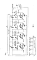
図1は、センサー12と、コンバータ段14、16、18及び20と、コントローラ22と、バッテリセル24、26、28及び30と、バス31と、充電ユニット32とを含む充電システム10を示す。コンバータ段14は、スイッチS41、S42、S43及びS44と、ダイオード50と、インダクター52と、キャパシター54とを含む。コンバータ段16は、スイッチS31、S32、S33及びS34と、ダイオード44と、インダクター46と、キャパシター48とを含む。コンバータ段18は、スイッチS21、S22、S23及びS24と、ダイオード38と、インダクター40と、キャパシター42とを含む。コンバータ段20は、スイッチS11、S12、S13及びS14と、ダイオード33と、インダクター34と、キャパシター36とを含む。バッテリセル24、26、28及び30(24〜30)は、直列に接続した四つのバッテリセルであって、該四つのバッテリセルはより大きなバッテリの一部である。各バッテリセルは、再充電可能なエネルギ蓄積ユニットである。各バッテリセルはサブバッテリセルから形成されても良い。各コンバータ段14、16、18及び20(14〜20)は、ソース構成、シンク構成、及び非シンク且つ非ソース(受動)構成の三つの構成の一つに構成できる。シンク構成では、コンバータ段は、対応するバッテリセルに充電電流を供給する。ソース構成では、コンバータ段は、対応するバッテリセルから電流を取り、その電流をシンク構成のコンバータ段に供給する。受動構成のコンバータ段は、電流を供給もシンクもしない。
FIG. 1 shows a
バッテリセル24は、陽極と、図で示していない陽極に接続されている陰極とを有する。バッテリセル26は、陽極と、バッテリセル24の陽極に接続されている陰極とを有する。バッテリセル28は、陽極と、バッテリセル26の陽極に接続されている陰極とを有する。バッテリセル30は、バッテリセル28の陽極に接続されている陰極と、OUT出力を供給する陽極とを有する。充電ユニット32は、OUTに接続されている第1端子と、最後のバッテリセル(図示せず。)の陰極に接続されている第2端子とを有する。センサー12は、バッテリセル24の陰極に接続されている第1入力と、バッテリセル24の陽極及びバッテリセル26の陰極に接続されているノードに接続されている第2に入力と、バッテリセル26の陽極及びバッテリセル28の陰極に接続されているノードに接続されている第3入力と、バッテリセル28の陽極及びバッテリセル30の陰極に接続されているノードに接続されている第4入力と、バッテリセル30の陽極に接続されている第5入力と、コントローラ22の入力に接続されている出力とを有する。コントローラ22は、各コンバータ段のスイッチを制御することによってコンバータ段の構成を設定する、各コンバータ段ごとの出力の組を有する。コンバータ段14は、スイッチS41、S42、S43及びS44を制御するための出力の組を受信する。コンバータ段16は、スイッチS31、S32、S33及びS34を制御するための出力の組を受信する。コンバータ段18は、スイッチS21、S22、S23及びS24を制御するための出力の組を受信する。コンバータ段20は、スイッチS11、S12、S13及びS14を制御するための出力の組を受信する。
The
コンバータ段14〜20の接続について、スイッチS41は、バッテリセル24の陽極に接続されている第1端子と、ダイオード50のアノードに接続されている第2端子とを有する。スイッチS42は、バッテリセル24の陽極に接続されている第1端子と、インダクター52の第1端子に接続されている第2端子とを有する。スイッチS43は、バッテリセル24の陰極に接続されている第1端子と、インダクター52の第1端子に接続されている第2端子とを有する。スイッチS44は、バッテリセル24の陰極に接続されている第1端子と、インダクター52の第2端子及びダイオード50のカソードに接続されている第2端子とを有する。キャパシター54は、インダクター52の第2端子に接続されている第1端子と、バス31に接続されている第2端子とを有する。スイッチS31は、バッテリセル26の陽極に接続されている第1端子と、ダイオード44のアノードに接続されている第2端子とを有する。スイッチS32は、バッテリセル26の陽極に接続されている第1端子と、インダクター46の第1端子に接続されている第2端子とを有する。スイッチS33は、バッテリセル26の陰極に接続されている第1端子と、インダクター46の第1端子に接続されている第2端子とを有する。スイッチS34は、バッテリセル26の陰極に接続されている第1端子と、インダクター46の第2端子及びダイオード44のカソードに接続されている第2端子とを有する。キャパシター48は、インダクター46の第2端子に接続されている第1端子と、バス31に接続されている第2端子とを有する。スイッチS21は、バッテリセル28の陽極に接続されている第1端子と、ダイオード38のアノードに接続されている第2端子とを有する。スイッチS22は、バッテリセル28の陽極に接続されている第1端子と、インダクター40の第1端子に接続されている第2端子とを有する。スイッチS23は、バッテリセル28の陰極に接続されている第1端子と、インダクター40の第1端子に接続されている第2端子とを有する。スイッチS24は、バッテリセル28の陰極に接続されている第1端子と、インダクター40の第2端子及びダイオード38のカソードに接続されている第2端子とを有する。キャパシター42は、インダクター40の第2端子に接続されている第1端子と、バス31に接続されている第2端子とを有する。スイッチS11は、バッテリセル30の陽極に接続されている第1端子と、ダイオード33のアノードに接続されている第2端子とを有する。スイッチS12は、バッテリセル30の陽極に接続されている第1端子と、インダクター34の第1端子に接続されている第2端子とを有する。スイッチS13は、バッテリセル30の陰極に接続されている第1端子と、インダクター34の第1端子に接続されている第2端子とを有する。スイッチS14は、バッテリセル30の陰極に接続されている第1端子と、インダクター34の第2端子及びダイオード32のカソードに接続されている第2端子とを有する。キャパシター36は、インダクター34の第2端子に接続されている第1端子と、バス31に接続されている第2端子とを有する。
For connection of converter stages 14-20, switch S 41 has a first terminal connected to the anode of
動作において、システム10は、充電ユニット32を介してバッテリセル24〜30を充電する。充電電流は、バッテリセル24〜30の陽極からバッテリセルを通って陰極に流れる。バッテリセルが充電される場合、センサー12は個別のバッテリセル電圧または他の特徴を検知し、その情報をコントローラ22に供給する。コントローラ22は、最高電圧または最高状態の電荷を有するバッテリセルに対応するコンバータ段をソース構成に構成し、最低電圧または最低状態の電荷を有するバッテリセルに対応するコンバータ段をシンク構成に構成することによって、応答する。他のコンバータ段は受動構成で維持する。それぞれソースまたはシンクとして使用されるよう選択されたバッテリセルは絶対最高電圧または絶対最低電圧を有するが、選択は、予想される低下または予想される異なる負荷のような他の基準に基づいても良い。このバランス工程の効果は、電力をシンクしているバッテリセルを充電する平均電流を増大させ、バランス電力をソースするバッテリセルを充電する平均電流を減少させることである。センサー12はバッテリセルの電圧を監視して、その情報をコントローラに結合し続ける。周期的にまたは異なるバッテリセルが最高または最低電圧になる時点で、対応するコンバータ段は適切な構成に切り替えられ、もはや最高または最低電圧ではないバッテリセルのコンバータ段は受動構成に切り替えられる。最低また最高電圧を有するバッテリセルを識別し、対応するコンバータ段のための適切な構成をもって応答する当該工程が続く。ある時点で、充電ユニット32は電流を供給するのを止める。コントローラ22は、全てのバッテリセルに対して等しい電荷状態を達成するために、充電ユニット32が電流の供給を止めた後でさえ、この工程を続けても良い。また、コントローラ20は、バッテリセルが電流を負荷(図示せず。)に供給している間、この工程を続けても良い。代替として、このバランス工程は充電ユニット32の充電が停止した時に止めても良い。バランス工程の間に、全てのバッテリセルが満足に平衡状態にされる場合は、全てのコンバータ段は受動構成に置かれる。図1が示すように、全てのコンバータ24〜30は、四つ全てのスイッチが開かれる構成である受動構成にある。一つのバッテリセルのみが異なるなら、等しい電圧の他のバッテリセルのいずれか一つは、対をなす他方のコンバータユニットとして選択されてよい。対を選択する一つの従来技術は、陰極側の異なる一つに最も近い一つを選択する。他の従来技術を使用しても良い。
In operation, the
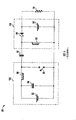
図2は、バッテリセル30が電流をシンクするバッテリセルであり且つバッテリセル24が電流をソースするバッテリセルである場合のために構成されたシステム10を示す。コンバータ段14はソース構成に置かれ、コンバータ段20はシンク構成に置かれている。他のコンバータ段は受動構成に維持する。コンバータ段14は、スイッチS42を閉じられ、パルス列に応答してスイッチS44が開成と閉成との間で切り替えられることによって、ソース構成に置かれる。閉じたスイッチS42は、インダクター52の第1端子をバッテリセル24の陽極に接続する効果を有する。スイッチS44の開閉は、パルス列に応答して、バッテリセル24の陰極をインダクター52の第2端子及びキャパシター54の第1端子に接続したりそれらから切り離したりする効果を有する。キャパシター54はバッテリセル24から電流をドレインするように、または少なくともバッテリセル24からの充電電流の一部を阻止するように、充電及び放電される。コンバータ段20は、スイッチS11及びS13を閉じられることによって、シンク構成に置かれる。スイッチS11を閉じられる効果は、ダイオード33のアノードをバッテリセル30の陽極に接続することである。スイッチS13を閉じられる効果は、インダクター34の第1端子をバッテリセル30の陰極に接続することである。シンク構成では、バス31におけるスイッチングは、電流が陽極から陰極へとバッテリセル30を流れるようにして、バッテリセル30の充電を増大させる効果を有する。
FIG. 2 shows the
図3は、システム10の作動を示す方法60を示す。ステップ62で示すように、最大過剰電荷を有するバッテリセルと、最大充電欠乏を有するバッテリセルとが決定される。通常、これは、それぞれ、最高電圧を有するバッテリセル及び最低電圧を有するバッテリセル、または最高充電状態のバッテリセル及び最低充電状態のバッテリセルに対応するが、必ずしもそうでなくともよい。ステップ64では、最低充電状態のバッテリセルのコンバータ段はシンク構成に置かれ、最高充電状態のバッテリセルのコンバータ段はソース構成に置かれる。ステップ66で示すように、これは、最低充電状態のバッテリセルを最高充電状態のバッテリセル2より充電する効果を有する。ステップ68で示すように、最高充電状態のバッテリセルが変化する場合、最高充電状態であったバッテリセルは、ステップ70で示すように、受動構成に変更され、新たな最高充電状態のバッテリセルはソース構成に変更される。従って、新たな最高充電状態のバッテリセルが最低充電状態のバッテリセルを充電することとなる。ステップ74で示すように、最低充電状態のバッテリセルが変化する場合、最低充電状態であったバッテリセルのコンバータ段は、ステップ75で示すように、受動構成に変換され、新たな最低充電状態のバッテリセルのコンバータ段がシンク構成に変換される。ステップ77で示すように、全てのバッテリセルは同一電圧である場合、全てのバッテリセルのコンバータ段は受動構成に変更され、工程は、ステップ79で示されるように、終了する。ステップ62が監視工程のいかなる時点で開始してもよいように、バッテリセルは継続的に監視される。この監視工程は、充電ユニット32が充電している時にのみに限定されていない。バッテリセルが出力電流OUTを供給している場合にも、方法60は使用されてよい。図4は、図3ほど詳細でないフローチャートを示すが、方法60の理解を助けとなるであろう。
FIG. 3 illustrates a method 60 that illustrates the operation of the
図5は、電圧源82と、キャパシター84と、インダクター86と、スイッチ88と、キャパシタンス90と、インダクター92と、ダイオード94と、キャパシター96とを含む、負荷98を駆動するシングルエンド一次インダクタンスコンバータ(SEPIC)80を示す。スイッチ88は、パルス例に応答して、開閉される。SEPIC80は電圧源82を用いて、負荷98の両端に、電圧源82の電圧より高いまたは低い電圧を供給する。SEPIC80は、キャパシタンス90を介して互いに結合されているソース部分102及びシンク部分104を有するように考えられる。ソース部分102は、電圧源82と、キャパシター84と、インダクター86と、スイッチ88とを含む。シンク部分104は、インダクター92、ダイオード94と、キャパシタンス96とを含む。シンク部分104及びソース部分102はキャパシタンス90によって絶縁され、負荷98の両端電圧は、電圧源82の電圧より高くても、または低くても、または等しくても良い。出力ドライブはパルス列のデューティサイクルによって制御される。
FIG. 5 illustrates a single-ended primary inductance converter that drives a
SEPIC80は、図2で示すようにシンク構成のコンバータ段20及びソース構成のコンバータ段14を有するバッテリセル30及びコンバータ段20と組み合わせたコンバータ段14及びバッテリセル24の動作と類似する。この構成において、ソース構成のコンバータ段14では、バッテリセル24は電圧源82と類似し、バッテリセル24のキャパシタンスはキャパシタンス84と類似し、インダクター52はインダクター86と類似する。類似する要素は同様に接続される。この構成において、コンバータ20では、バッテリセル30のキャパシタンスはキャパシタンス96と類似し、ダイオード33はダイオード94と類似し、インダクター34はインダクター92と類似する。コンバータ段14では、類似する要素は同様に接続される。バス34を介して直列に接続されるキャパシター54及び36の組み合わせは、SEPIC80のキャパシタンス90と類似する。従って、ソース構成のコンバータ段14及びシンク構成のコンバータ段20の組み合わせは、SEPICである。各コンバータ段は、シンク構成またはソース構成であってよく、ソース構成の一つ及びシンク構成の一つの組み合わせである一対のコンバータ段である場合、SEPICが結果になる。従って、SEPICはこの応用に特に有利であるが、他のコンバータをより高い電荷状態を有するバッテリセルからより低い電荷状態を有するバッテリセルを直接的に充電するように使用できる。
The
以上より、明らかなように、直列に接続されている少なくとも三つのバッテリセルを含む直列に接続された複数のバッテリセルを含むバッテリシステムの動作方法が提供される。該方法は、複数のバッテリセルから最大過剰電荷を有するバッテリセルを決定するステップを含む。該方法は、複数のバッテリセルから最大電荷欠乏を有するバッテリセルを決定するステップを含む。該方法は、最大電荷欠乏を有するバッテリセルを充電するために、電圧コンバータによって、最大過剰電荷を有するバッテリセルを放電する。該方法は、電圧コンバータがSEPIC電圧コンバータであることをさらに特徴とする。該方法は、複数のコンバータ段をさらに含み、複数のコンバータ段の各コンバータ段は複数のバッテリセルのバッテリセルに関連し、該放電するステップは、電圧コンバータのソース段として前記最大過剰充電を有するバッテリセルに関連するコンバータ段を使用するステップと、電圧コンバータのシンク段として前記最大充電欠乏を有するバッテリセルに関連するコンバータ段を使用するステップとを含む。該方法は、放電するステップ後、複数のバッテリセルから最大電荷欠乏を有する第2バッテリセルを決定するステップと、該決定後、前記電圧コンバータによって前記第2バッテリセルを充電するために前記最大過剰電荷を有するバッテリセルを放電するステップとを更に含み、前記第2バッテリセルを決定した後の放電ステップは、前記電圧コンバータのソース段として前記最大過剰電荷を有するバッテリセルに関連するコンバータ段を使用し、前記電圧コンバータのシンク段として前記第2バッテリセルに関連するコンバータ段を使用するステップを含む。該方法は、バッテリセルを放電する間に、前記第2バッテリセルに関連するコンバータ段が受動構成において構成され、前記第2バッテリセルを決定した後の放電ステップの間に、放電のためにシンク段として使用されるコンバータ段は受動構成において構成されることをさらに特徴とする。代替的に、該方法は、前記放電ステップ後、複数のバッテリセルの中から最大過剰電荷を有する第2バッテリセルを決定するステップと、該決定後、前記電圧コンバータによって前記最大電荷欠乏を有するバッテリセルを充電するために前記第2バッテリセルを放電するステップとをさらに含んでも良く、前記第2バッテリを決定した後の放電ステップは、前記電圧コンバータのソース段として前記第2バッテリセルのコンバータ段を使用し、前記電圧コンバータのシンク段として前記最大電荷欠乏に関連するバッテリセルのコンバータ段を使用することを含む。また、代替的に、該方法は、前記放電ステップ後、決定動作を実行するステップをさらに含んでもよく、該実行するステップは、複数のバッテリセルの中から最大電荷欠乏を有するバッテリセル及び最大過剰電荷を有するバッテリセルを決定し、それによって、決定した最大電荷欠乏を有するバッテリセルを充電するために電圧コンバータによって最大過剰電荷を有するバッテリセルを放電するステップをさらに含んでも良い。該方法は、該放電するステップが複数のバッテリセルの充電動作の間に実行されることをさらに特徴としても良い。該方法は、複数のバッテリセルが負荷に電力を供給する間に該放電するステップが実行されることをさらに特徴としても良い。 As is apparent from the above, a method of operating a battery system including a plurality of battery cells connected in series including at least three battery cells connected in series is provided. The method includes determining a battery cell having a maximum excess charge from a plurality of battery cells. The method includes determining a battery cell having a maximum charge deficiency from a plurality of battery cells. The method discharges a battery cell having a maximum excess charge by a voltage converter to charge a battery cell having a maximum charge deficiency. The method is further characterized in that the voltage converter is a SEPIC voltage converter. The method further includes a plurality of converter stages, wherein each converter stage of the plurality of converter stages is associated with a battery cell of the plurality of battery cells, and the discharging step has the maximum overcharge as a source stage of the voltage converter. Using a converter stage associated with the battery cell and using a converter stage associated with the battery cell having the maximum charge depletion as the sink stage of the voltage converter. The method includes determining, after the discharging step, a second battery cell having a maximum charge deficiency from a plurality of battery cells, and, after the determination, the maximum excess for charging the second battery cell by the voltage converter. Discharging a battery cell having a charge, wherein the discharging step after determining the second battery cell uses a converter stage associated with the battery cell having the maximum excess charge as a source stage of the voltage converter. And using a converter stage associated with the second battery cell as the sink stage of the voltage converter. The method includes sinking for discharging during a discharging step after the converter stage associated with the second battery cell is configured in a passive configuration and discharging the second battery cell while discharging the battery cell. The converter stage used as the stage is further characterized in that it is configured in a passive configuration. Alternatively, the method includes determining, after the discharging step, a second battery cell having a maximum excess charge from among a plurality of battery cells; and after the determination, the battery having the maximum charge deficiency by the voltage converter. Discharging the second battery cell to charge the cell, wherein the discharging step after determining the second battery includes a converter stage of the second battery cell as a source stage of the voltage converter. And using the converter stage of the battery cell associated with the maximum charge depletion as the sink stage of the voltage converter. Alternatively, the method may further include performing a decision operation after the discharging step, the performing step including a battery cell having a maximum charge deficiency and a maximum excess from a plurality of battery cells. The method may further include determining a battery cell having a charge, and thereby discharging the battery cell having the maximum excess charge by a voltage converter to charge the battery cell having the determined maximum charge deficiency. The method may be further characterized in that the discharging step is performed during a charging operation of a plurality of battery cells. The method may be further characterized in that the discharging step is performed while a plurality of battery cells provide power to the load.
直列に接続した少なくとも三つのバッテリセルを有する複数のバッテリセルの動作を制御する回路も開示されている。該回路はバスを含む。該回路は複数のコンバータ段を含み、各コンバータ段はバスに接続され、複数のバッテリセルの一つのバッテリセルに関連し、電圧コンバータのソース段として働いて、該ソース段に関連するバッテリセルを、バスを介して複数のバッテリセルの別のバッテリセルを充電するために放電するよう構成可能であり、電圧コンバータのシンク段として働いて、該シンク段に関連するバッテリセルをバスを介して複数のバッテリセルの別のバッテリセルから充電するよう構成可能である。該回路は複数のコンバータ段の複数の構成を制御する制御回路機構を含む。該回路は、コンバータ段の各コンバータ段がシングルエンド一次インダクタンスコンバータ(SEPIC)のソース段として構成であり、且つ、前記複数のコンバータ段の各コンバータ段がシングルエンド一次インダクタンスコンバータ(SEPIC)のシンク段として構成可能であることをさらに特徴としても良い。該回路は、複数のコンバータ段の各コンバータ段がインダクター、スイッチ及びキャパシターを含むことをさらに特徴としても良い。該回路は、複数のコンバータ段の各コンバータ段のキャパシターがバスに接続されることをさらに特徴としても良い。該回路は、複数のコンバータ段の各コンバータ段がインダクターを含むことをさらに特徴としても良く、各コンバータ段が電圧コンバータのソース段として構成された場合に、前記インダクターの第1端子は各コンバータ段に関連するバッテリセルの陽極に接続され、各コンバータ段が電圧コンバータのシンク段として構成された場合に、前記インダクターの第1の端子は各コンバータ段に関連するバッテリセルの陰極に接続される。該回路は、各コンバータ段が受動構成において構成される場合に、前記インダクターの第1端子が各コンバータ段に関連するバッテリセルの陰極または陽極に接続されないことをさらに特徴としても良い。該回路は、複数のコンバータ段の各コンバータ段が、各コンバータ段のインダクターの第2端子に接続される第1端子と、各コンバータ段に関連するバッテリセルの陰極に接続される第2端子とを有するスイッチを含むことをさらに特徴としても良く、コンバータ段が電圧コンバータのソース段として構成される場合に、制御回路機構は、コンバータ段のスイッチの導通を制御するためにパルス幅変調信号を供給する。該回路は、コントローラが、等化動作の間に、最大電荷欠乏を有すると決定されたバッテリセルを充電するために、電圧コンバータのソース段として、複数のコンバータ段の中から、複数のバッテリセルから最大過剰電荷を有すると決定されたバッテリセルに関連するコンバータ段を構成し、電圧コンバータのシンク段として、複数のコンバータ段の中から、複数のバッテリセルから最大電荷欠乏を有すると決定されたバッテリセルに関連するコンバータ段を構成することをさらに特徴としても良い。該回路は、コントローラが、等化動作の間に、ソース段として、複数のコンバータ段から一つのコンバータ段のみを構成し、シンク段として複数のコンバータ段から一つのコンバータ段のみを構成することさらに特徴としても良い。 A circuit for controlling the operation of a plurality of battery cells having at least three battery cells connected in series is also disclosed. The circuit includes a bus. The circuit includes a plurality of converter stages, each converter stage being connected to a bus, associated with one battery cell of the plurality of battery cells, and acting as a source stage for a voltage converter to connect a battery cell associated with the source stage. Can be configured to discharge to charge another battery cell of the plurality of battery cells via the bus, and act as a sink stage for the voltage converter, and a plurality of battery cells associated with the sink stage via the bus The battery cell can be configured to be charged from another battery cell. The circuit includes a control circuitry that controls a plurality of configurations of the plurality of converter stages. In the circuit, each converter stage of the converter stage is configured as a source stage of a single-ended primary inductance converter (SEPIC), and each converter stage of the plurality of converter stages is a sink stage of a single-ended primary inductance converter (SEPIC). It is good also as a characteristic that it can comprise as. The circuit may be further characterized in that each converter stage of the plurality of converter stages includes an inductor, a switch and a capacitor. The circuit may be further characterized in that a capacitor of each converter stage of the plurality of converter stages is connected to the bus. The circuit may be further characterized in that each of the plurality of converter stages includes an inductor, and when each converter stage is configured as a source stage of a voltage converter, the first terminal of the inductor is each converter stage. When each converter stage is configured as a sink stage of a voltage converter, the first terminal of the inductor is connected to the cathode of the battery cell associated with each converter stage. The circuit may be further characterized in that when each converter stage is configured in a passive configuration, the first terminal of the inductor is not connected to the cathode or anode of the battery cell associated with each converter stage. The circuit includes a first terminal in which each converter stage of the plurality of converter stages is connected to a second terminal of an inductor in each converter stage, and a second terminal connected to a cathode of a battery cell associated with each converter stage. The control circuitry may provide a pulse width modulated signal to control conduction of the switch of the converter stage when the converter stage is configured as a source stage of a voltage converter. To do. The circuit includes a plurality of battery cells from among a plurality of converter stages as a source stage of a voltage converter for charging a battery cell determined to have a maximum charge deficiency during an equalization operation. The converter stage associated with the battery cell determined to have the maximum excess charge from is configured and as the sink stage of the voltage converter, from among the plurality of converter stages, determined to have the maximum charge deficiency from the plurality of battery cells It may be further characterized by configuring a converter stage associated with the battery cell. In the circuit, the controller configures only one converter stage from a plurality of converter stages as a source stage and configures only one converter stage from a plurality of converter stages as a sink stage during an equalization operation. It is good as a feature.
直列に接続した複数のバッテリセルの動作を制御する回路も開示されている。該回路は、複数のバッテリセルの各バッテリセルの電荷の状態を決定するためのセンサー回路機構を含む。該回路は第1コンバータ段を含む。該回路は、少なくとも一つのキャパシターによって第1コンバータ段に接続される第2コンバータ段を含む。該回路は制御回路機構を含み、バッテリセルの等化動作の間に、前記制御回路機構は、前記第1コンバータ段がシングルエンド一次インダクタンスコンバータ(SEPIC)のソース段であって、前記第2コンバータ段がSEPICコンバータのシンク段であることを可能にし、複数のバッテリセルの中の第1バッテリセルを放電して、複数のバッテリセルの中の第2バッテリセルを充電するために電荷を第2バッテリセルに転送するようにする。該回路は、前記第1コンバータ段が第1インダクターを含み、前記第2コンバータ段が第2インダクターを含み、前記第1インダクター及び前記第2インダクターが少なくとも一つのキャパシターによって接続されることをさらに特徴とする。 A circuit for controlling the operation of a plurality of battery cells connected in series is also disclosed. The circuit includes a sensor circuit mechanism for determining the state of charge of each battery cell of the plurality of battery cells. The circuit includes a first converter stage. The circuit includes a second converter stage connected to the first converter stage by at least one capacitor. The circuit includes a control circuit mechanism, wherein during the equalization operation of the battery cell, the control circuit mechanism is configured such that the first converter stage is a source stage of a single-ended primary inductance converter (SEPIC) and the second converter Enabling the stage to be a sink stage of a SEPIC converter, discharging a first battery cell in the plurality of battery cells and charging a second charge to charge a second battery cell in the plurality of battery cells. Transfer to the battery cell. The circuit further includes the first converter stage including a first inductor, the second converter stage including a second inductor, and the first inductor and the second inductor are connected by at least one capacitor. And
本発明を実行する装置は当業者が周知である電子部分及び回路からなるので、本発明の説明を理解するために回路の詳細はこれ以上に説明しない。上記の明細書により、本発明は特定の実施形態に基づいて記載されてきた。しかし、当業者には明らかなように、様々な変更や変形は、添付した本発明の特許請求の範囲に反することなく行われてよい。例えば、スイッチにおいてMOSトランジスタを使用するのは好ましいが、他のスイッチをしても良い。従って、明細書及び図面は、本発明を説明するためのものであり、本発明を限定するためのものではない。また、明細書及び図面に開示されている実施形態に対する全ての変更は、本発明の技術的範囲に内包されるものである。 Since the apparatus for carrying out the present invention consists of electronic parts and circuits that are well known to those skilled in the art, the details of the circuits will not be further described in order to understand the description of the present invention. From the foregoing specification, the invention has been described with reference to specific embodiments. However, it will be apparent to those skilled in the art that various modifications and variations can be made without departing from the scope of the appended claims. For example, it is preferable to use a MOS transistor in the switch, but another switch may be used. Accordingly, the specification and drawings are for purposes of illustrating the invention and are not intended to limit the invention. Moreover, all the changes with respect to embodiment disclosed by this specification and drawing are included in the technical scope of this invention.
本発明は、特定の導電性及び極性に対して説明されてきたが、当業者には明らかなように、それらの導電性及び極性は逆にされてもよい。 Although the present invention has been described with respect to particular conductivity and polarity, as will be apparent to those skilled in the art, the conductivity and polarity may be reversed.
「接続された」という語は必ずしも直接的に、また機械的に結合する状態を意味するものではない。 The term “connected” does not necessarily imply a state of direct and mechanical coupling.
この書類において、「第1の」や「第2の」等の関係語は、ある実体や動作を別の実体や動作と区別するためのみに使用され得るものであり、これらの実体や動作の間には、このような実際の関係性や順序が必ずしも必要されるわけではない。 In this document, relational words such as “first” and “second” can be used only to distinguish one entity or action from another entity or action. In the meantime, such an actual relationship or order is not necessarily required.
10 システム
12 センサー
14〜20 コンバータ段
22 コントローラ
22〜30 バッテリセル
32 充電ユニット
80 シングルエンド一次インダクタンスコンバータ(SEPIC)
102 ソース部分
104 シンク部分
10
102
Claims (20)
前記複数のバッテリセル中で最大過剰電荷を有するバッテリセルを決定するステップと、
前記複数のバッテリセル中で最大電荷欠乏を有するバッテリセルを決定するステップと、
電圧コンバータによって前記最大電荷欠乏を有するバッテリセルを充電するために前記最大過剰電荷を有するバッテリセルを放電するステップと
を含む方法。 A method of operating a battery system having a plurality of battery cells connected in series, wherein the plurality of battery cells have at least three battery cells connected in series.
Determining a battery cell having a maximum excess charge among the plurality of battery cells;
Determining a battery cell having a maximum charge deficiency among the plurality of battery cells;
Discharging the battery cell having the maximum excess charge to charge the battery cell having the maximum charge deficiency by a voltage converter.
請求項1に記載の方法。 The voltage converter comprises a SEPIC voltage converter;
The method of claim 1.
前記複数のコンバータ段の各コンバータ段は、前記複数のバッテリセルの一つのバッテリセルに関連づけられ、
前記放電ステップは、
前記電圧コンバータのソース段として前記最大過剰電荷を有するバッテリセルに関連するコンバータ段を使用し、前記電圧コンバータのシンク段として前記最大電荷欠乏を有するバッテリセルに関連するコンバータ段を使用するステップを含む、
請求項1に記載の方法。 The voltage converter has a plurality of converter stages,
Each converter stage of the plurality of converter stages is associated with one battery cell of the plurality of battery cells;
The discharging step includes
Using a converter stage associated with the battery cell having the maximum excess charge as a source stage of the voltage converter and using a converter stage associated with the battery cell having the maximum charge depletion as a sink stage of the voltage converter. ,
The method of claim 1.
前記第2バッテリセルを決定した後、前記電圧コンバータによって前記第2バッテリセルを充電するために前記最大過剰電荷を有するバッテリセルを放電するステップと
をさらに含み、
前記第2バッテリセルを決定した後の放電ステップは、前記電圧コンバータのソース段として前記最大過剰電荷を有するバッテリセルに関連するコンバータ段を使用し、前記電圧コンバータのシンク段として前記第2バッテリセルに関連するコンバータ段を使用するステップを含む、
請求項3に記載の方法。 After the discharging step, determining a second battery cell having a maximum charge deficiency among the plurality of battery cells;
After determining the second battery cell, discharging the battery cell having the maximum excess charge to charge the second battery cell by the voltage converter;
The discharging step after determining the second battery cell uses a converter stage associated with the battery cell having the maximum excess charge as a source stage of the voltage converter, and the second battery cell as a sink stage of the voltage converter. Including using a converter stage associated with
The method of claim 3.
前記第2のバッテリセルを決定した後の放電ステップを実行する間に、放電のためにシンク段として使用されるコンバータ段は受動構成で構成される、
請求項4に記載の方法。 While performing the step of discharging the battery cell, the converter stage associated with the second battery cell is configured in a passive configuration;
While performing the discharging step after determining the second battery cell, the converter stage used as a sink stage for discharging is configured in a passive configuration,
The method of claim 4.
前記第2バッテリセルを決定した後、前記電圧コンバータによって前記最大電荷欠乏を有するバッテリセルを充電するために前記第2バッテリセルを放電するステップと
をさらに含み、
前記第2バッテリセルを決定した後の放電ステップは、前記電圧コンバータのソース段として前記第2バッテリセルのコンバータ段を使用し、前記電圧コンバータのシンク段として前記最大電荷欠乏を有するバッテリセルに関連するコンバータ段を使用するステップを含む、
請求項3に記載の方法。 Determining a second battery cell having a maximum excess charge among the plurality of battery cells after the discharging step;
After determining the second battery cell, discharging the second battery cell to charge the battery cell having the maximum charge deficiency by the voltage converter;
The discharging step after determining the second battery cell uses the converter stage of the second battery cell as the source stage of the voltage converter and relates to the battery cell having the maximum charge deficiency as the sink stage of the voltage converter Including using a converter stage to
The method of claim 3.
前記電圧コンバータによって、前記決定動作を実行するステップによって決定された前記最大電荷欠乏を有するバッテリセルを充電するために、前記決定動作を実行するステップによって決定された前記最大過剰電荷を有するバッテリセルを放電するステップと
をさらに含む請求項1に記載の方法。 After the discharging step, performing a determining operation including determining a battery cell having a maximum charge deficiency among the plurality of battery cells and determining a battery cell having a maximum excess charge among the plurality of battery cells. When,
To charge the battery cell having the maximum charge deficiency determined by the step of performing the determination operation by the voltage converter, the battery cell having the maximum excess charge determined by the step of performing the determination operation. The method of claim 1, further comprising: discharging.
請求項1に記載の方法。 Performing the discharging step during a charging operation of the plurality of battery cells;
The method of claim 1.
請求項1に記載の方法。 Performing the discharging step while the plurality of battery cells supply power to a load;
The method of claim 1.
前記複数のバッテリセルの各バッテリセルの電荷の状態を決定するセンサー回路機構と、
バスと、
前記バスにそれぞれ接続される複数のコンバータ段と、
前記複数のコンバータ段の構成を制御するための制御回路機構と
を含み、
前記複数のコンバータ段の各コンバータ段は、前記複数のバッテリセルの各バッテリセルに関連づけられ、
前記複数のコンバータ段の各コンバータ段は、電圧コンバータのソース段として働いて、前記バスを介して前記複数のバッテリセルの別のバッテリセルを充電するように該ソース段に関連するバッテリセルを放電するよう構成可能であり、
前記複数のコンバータ段の各コンバータ段は、電圧コンバータのシンク段として働いて、前記バスを介して前記複数のバッテリセルの別のバッテリセルから該シンク段に関連する前記複数のバッテリセルの一つのバッテリセルを充電するよう構成可能である、
回路。 A circuit for controlling operations of a plurality of battery cells connected in series, wherein the plurality of battery cells includes at least three battery cells.
A sensor circuit mechanism for determining a state of charge of each battery cell of the plurality of battery cells;
With bus,
A plurality of converter stages each connected to the bus;
A control circuit mechanism for controlling the configuration of the plurality of converter stages,
Each converter stage of the plurality of converter stages is associated with each battery cell of the plurality of battery cells;
Each converter stage of the plurality of converter stages acts as a source stage for a voltage converter and discharges a battery cell associated with the source stage to charge another battery cell of the plurality of battery cells via the bus. And can be configured to
Each converter stage of the plurality of converter stages acts as a sink stage for a voltage converter and from one of the plurality of battery cells via the bus to one of the plurality of battery cells associated with the sink stage. Configurable to charge the battery cell;
circuit.
前記複数のコンバータ段の各コンバータ段は、シングルエンド一次インダクタンスコンバータ(SEPIC)のシンク段として構成可能である、
請求項10記載の回路。 Each converter stage of the plurality of converter stages can be configured as a source stage of a single-ended primary inductance converter (SEPIC), and each converter stage of the plurality of converter stages is a sink of a single-ended primary inductance converter (SEPIC) Can be configured as a stage,
The circuit according to claim 10.
請求項10記載の回路。 Each converter stage of the plurality of converter stages includes an inductor, a switch, and a capacitor.
The circuit according to claim 10.
請求項12記載の回路。 The capacitor of each converter stage of the plurality of converter stages is connected to the bus;
The circuit according to claim 12.
前記複数のコンバータ段の各コンバータ段が前記電圧コンバータのソース段として構成される場合に、前記インダクターの第1端子は各コンバータ段に関連したバッテリセルの正極端子に接続され、
前記複数のコンバータ段の各コンバータ段が前記電圧コンバータのシンク段として構成される場合に、前記インダクターの前記第1端子は各コンバータ段に関連したバッテリセルの陰極端子に接続される、
請求項10記載の回路。 Each converter stage of the plurality of converter stages includes an inductor;
When each converter stage of the plurality of converter stages is configured as a source stage of the voltage converter, the first terminal of the inductor is connected to a positive terminal of a battery cell associated with each converter stage;
When each converter stage of the plurality of converter stages is configured as a sink stage of the voltage converter, the first terminal of the inductor is connected to a cathode terminal of a battery cell associated with each converter stage;
The circuit according to claim 10.
請求項14記載の回路。 When each converter stage is configured in a passive configuration, the first terminal of the inductor is not connected to the negative or positive terminal of the battery cell associated with each converter stage;
The circuit of claim 14.
各コンバータ段が前記電圧コンバータのソース段として構成される場合に、前記制御回路機構は、当該コンバータ段のスイッチの導通を制御するためにパルス幅変調信号を供給する、
請求項14記載の回路。 Each converter stage of the plurality of converter stages has a first terminal connected to the second terminal of the inductor of each converter stage and a second terminal connected to the cathode terminal of the battery cell associated with each converter stage. Including a switch having
When each converter stage is configured as a source stage of the voltage converter, the control circuitry provides a pulse width modulated signal to control conduction of the switch of the converter stage.
The circuit of claim 14.
請求項10記載の回路。 During the equalization operation, the controller configures, from among the plurality of converter stages, a converter stage associated with the battery cell determined to have a maximum excess charge from the plurality of battery cells as a source stage of the voltage converter. And a converter stage associated with a battery cell determined to have a maximum charge deficiency from the plurality of battery cells among the plurality of converter stages is configured as a sink stage of the voltage converter, and the maximum charge Supplying a charge to charge a battery cell determined to have a deficiency;
The circuit according to claim 10.
ソース段として前記複数のコンバータ段の一つのコンバータ段のみを構成し、
シンク段として前記複数のコンバータ段の一つのコンバータ段のみを構成する、
請求項10記載の回路。 During the equalization operation, the controller
Configure only one converter stage of the plurality of converter stages as a source stage,
Constituting only one converter stage of the plurality of converter stages as a sink stage;
The circuit according to claim 10.
前記複数のバッテリセルの各バッテリセルの電荷の状態を決定するセンサー回路機構と、
第1コンバータ段と、
少なくとも一つのキャパシターによって前記第1コンバータ段に接続される第2コンバータ段と、
制御回路機構と
を含み、
バッテリセル等化動作の間、前記制御回路機構は、前記第1コンバータ段がシングルエンド一次インダクタンスコンバータ(SEPIC)のソース段であり且つ前記第2コンバータ段が前記SEPICのシンク段であることを可能にするよう制御信号を供給して、前記複数のバッテリセルの第2バッテリセルを充電するために電荷を該第2バッテリセルに転送するよう前記複数のバッテリセルの第1バッテリセルが放電されるようにする、
回路。 A circuit for controlling operations of a plurality of battery cells connected in series,
A sensor circuit mechanism for determining a state of charge of each battery cell of the plurality of battery cells;
A first converter stage;
A second converter stage connected to the first converter stage by at least one capacitor;
Control circuit mechanism and
During battery cell equalization operations, the control circuitry allows the first converter stage to be the source stage of a single-ended primary inductance converter (SEPIC) and the second converter stage to be the sink stage of the SEPIC. The first battery cells of the plurality of battery cells are discharged to transfer a charge to the second battery cells to charge the second battery cells of the plurality of battery cells. To
circuit.
前記第2コンバータ段は第2インダクターを含み、
前記第1インダクター及び前記第2インダクターは、前記少なくとも一つのキャパシターによって接続される、
請求項19記載の回路。 The first converter stage includes a first inductor;
The second converter stage includes a second inductor;
The first inductor and the second inductor are connected by the at least one capacitor;
The circuit of claim 19.
Applications Claiming Priority (2)
| Application Number | Priority Date | Filing Date | Title |
|---|---|---|---|
| US12/833,430 | 2010-07-09 | ||
| US12/833,430 US8436582B2 (en) | 2010-07-09 | 2010-07-09 | Battery cell equalizer system |
Publications (2)
| Publication Number | Publication Date |
|---|---|
| JP2012019685A true JP2012019685A (en) | 2012-01-26 |
| JP2012019685A5 JP2012019685A5 (en) | 2014-08-14 |
Family
ID=44744768
Family Applications (1)
| Application Number | Title | Priority Date | Filing Date |
|---|---|---|---|
| JP2011151482A Pending JP2012019685A (en) | 2010-07-09 | 2011-07-08 | Operation method and circuit of battery system with a plurality of battery cells |
Country Status (4)
| Country | Link |
|---|---|
| US (1) | US8436582B2 (en) |
| EP (1) | EP2405554B1 (en) |
| JP (1) | JP2012019685A (en) |
| CN (1) | CN102315671B (en) |
Cited By (1)
| Publication number | Priority date | Publication date | Assignee | Title |
|---|---|---|---|---|
| JP2014193111A (en) * | 2013-03-27 | 2014-10-06 | Egcns Co Ltd | Direct current micro-grid charge/discharge system for plural secondary batteries connected in series |
Families Citing this family (38)
| Publication number | Priority date | Publication date | Assignee | Title |
|---|---|---|---|---|
| US8319471B2 (en) | 2006-12-06 | 2012-11-27 | Solaredge, Ltd. | Battery power delivery module |
| US11569659B2 (en) | 2006-12-06 | 2023-01-31 | Solaredge Technologies Ltd. | Distributed power harvesting systems using DC power sources |
| US9088178B2 (en) | 2006-12-06 | 2015-07-21 | Solaredge Technologies Ltd | Distributed power harvesting systems using DC power sources |
| US8947194B2 (en) | 2009-05-26 | 2015-02-03 | Solaredge Technologies Ltd. | Theft detection and prevention in a power generation system |
| US11687112B2 (en) | 2006-12-06 | 2023-06-27 | Solaredge Technologies Ltd. | Distributed power harvesting systems using DC power sources |
| US11309832B2 (en) | 2006-12-06 | 2022-04-19 | Solaredge Technologies Ltd. | Distributed power harvesting systems using DC power sources |
| US11735910B2 (en) | 2006-12-06 | 2023-08-22 | Solaredge Technologies Ltd. | Distributed power system using direct current power sources |
| US8531055B2 (en) | 2006-12-06 | 2013-09-10 | Solaredge Ltd. | Safety mechanisms, wake up and shutdown methods in distributed power installations |
| US8473250B2 (en) | 2006-12-06 | 2013-06-25 | Solaredge, Ltd. | Monitoring of distributed power harvesting systems using DC power sources |
| US8319483B2 (en) | 2007-08-06 | 2012-11-27 | Solaredge Technologies Ltd. | Digital average input current control in power converter |
| US8013472B2 (en) | 2006-12-06 | 2011-09-06 | Solaredge, Ltd. | Method for distributed power harvesting using DC power sources |
| US11888387B2 (en) | 2006-12-06 | 2024-01-30 | Solaredge Technologies Ltd. | Safety mechanisms, wake up and shutdown methods in distributed power installations |
| US8963369B2 (en) | 2007-12-04 | 2015-02-24 | Solaredge Technologies Ltd. | Distributed power harvesting systems using DC power sources |
| US11855231B2 (en) | 2006-12-06 | 2023-12-26 | Solaredge Technologies Ltd. | Distributed power harvesting systems using DC power sources |
| US11728768B2 (en) | 2006-12-06 | 2023-08-15 | Solaredge Technologies Ltd. | Pairing of components in a direct current distributed power generation system |
| EP3719949A1 (en) | 2008-05-05 | 2020-10-07 | Solaredge Technologies Ltd. | Direct current power combiner |
| EP2532068B1 (en) * | 2010-02-05 | 2014-08-13 | Commissariat à l'Énergie Atomique et aux Énergies Alternatives | Charge equalization system for batteries |
| US10673229B2 (en) | 2010-11-09 | 2020-06-02 | Solaredge Technologies Ltd. | Arc detection and prevention in a power generation system |
| US9099870B2 (en) * | 2011-06-11 | 2015-08-04 | Sendyne Corporation | Charge redistribution method for cell arrays |
| EP2549619A1 (en) * | 2011-07-19 | 2013-01-23 | Kabushiki Kaisha Toyota Jidoshokki | Charge and discharge control apparatus |
| JP6176113B2 (en) * | 2011-09-02 | 2017-08-09 | 日本電気株式会社 | Battery control system, battery control device, battery control method, and program |
| GB2498365A (en) | 2012-01-11 | 2013-07-17 | Solaredge Technologies Ltd | Photovoltaic module |
| GB2498790A (en) | 2012-01-30 | 2013-07-31 | Solaredge Technologies Ltd | Maximising power in a photovoltaic distributed power system |
| GB2498791A (en) | 2012-01-30 | 2013-07-31 | Solaredge Technologies Ltd | Photovoltaic panel circuitry |
| CN103368268B (en) * | 2012-03-27 | 2015-04-15 | 无锡富洪科技有限公司 | Active voltage balancing system and active voltage balancing method for serial energy storage element group |
| KR101326103B1 (en) * | 2012-03-29 | 2013-11-06 | 숭실대학교산학협력단 | Apparatus for balancing of battery charge amount, and system thereof |
| US9583957B2 (en) * | 2012-09-10 | 2017-02-28 | Silicon Works Co., Ltd. | Cell balancing integrated circuit, cell balancing system, and cell balancing method |
| KR101450717B1 (en) * | 2013-01-18 | 2014-10-16 | 포항공과대학교 산학협력단 | Battery cell ballancing circuit using series resonant circuit |
| US9548619B2 (en) * | 2013-03-14 | 2017-01-17 | Solaredge Technologies Ltd. | Method and apparatus for storing and depleting energy |
| JP5975169B2 (en) * | 2013-03-29 | 2016-08-23 | 日本電気株式会社 | Charge / discharge device, charge / discharge control method, and program |
| US9203246B2 (en) * | 2013-05-16 | 2015-12-01 | Postech Academy-Industry Foundation | Balancing control circuit for battery cell module using LC series resonant circuit |
| US9748785B2 (en) * | 2014-03-04 | 2017-08-29 | Ricoh Company, Ltd. | Storage status adjusting circuit, storage status adjusting device, storage battery pack and switch circuit controlling method |
| CN105449734A (en) * | 2015-06-02 | 2016-03-30 | 武汉众宇动力系统科技有限公司 | Battery balancing device and charge and discharge balancing method thereof |
| KR101917913B1 (en) | 2015-07-23 | 2018-11-12 | 주식회사 엘지화학 | Apparatus for balancing battery stack |
| US11177663B2 (en) | 2016-04-05 | 2021-11-16 | Solaredge Technologies Ltd. | Chain of power devices |
| WO2018134827A1 (en) * | 2017-01-23 | 2018-07-26 | B.G. Negev Technologies And Applications Ltd., At Ben-Gurion University | System for balancing a series of cells |
| CN107171416B (en) * | 2017-07-25 | 2023-07-07 | 贵州大学 | Novel equalizing circuit and control method thereof |
| CN113708466B (en) * | 2021-10-25 | 2022-03-11 | 广东希荻微电子股份有限公司 | Battery charging and discharging circuit and terminal equipment |
Citations (3)
| Publication number | Priority date | Publication date | Assignee | Title |
|---|---|---|---|---|
| JPH1032936A (en) * | 1996-07-12 | 1998-02-03 | Tokyo R & D:Kk | Control system and method for power supply |
| JP2000014031A (en) * | 1997-10-30 | 2000-01-14 | Lockheed Martin Corp | Method for equalizing voltage of traction battery module of hybrid electric vehicle |
| JP2002223528A (en) * | 2000-11-21 | 2002-08-09 | Nagano Japan Radio Co | Voltage equalizer for storage element |
Family Cites Families (12)
| Publication number | Priority date | Publication date | Assignee | Title |
|---|---|---|---|---|
| US5659237A (en) * | 1995-09-28 | 1997-08-19 | Wisconsin Alumni Research Foundation | Battery charging using a transformer with a single primary winding and plural secondary windings |
| FR2776139B1 (en) * | 1998-03-13 | 2002-03-08 | Denso Corp | DEVICE FOR BALANCING VOLTAGES IN A COMPOSITE BATTERY |
| US6373223B1 (en) * | 2000-11-21 | 2002-04-16 | Nagano Japan Radio Co., Ltd. | Voltage equalizing apparatus and voltage equalizing method for battery devices |
| TW571452B (en) * | 2002-12-13 | 2004-01-11 | Quanta Comp Inc | Charging-type electrical potential balance device |
| JP3795499B2 (en) * | 2003-12-26 | 2006-07-12 | 富士重工業株式会社 | Voltage equalization device for storage element |
| KR100666817B1 (en) * | 2005-01-14 | 2007-01-09 | 주식회사 엘지화학 | Apparatus and method for balancing battery |
| JP2006246645A (en) * | 2005-03-04 | 2006-09-14 | Yazaki Corp | Equalization method and its device |
| US7592775B2 (en) * | 2006-05-31 | 2009-09-22 | Aeroflex Plainview, Inc. | Battery balancing including resonant frequency compensation |
| KR101124800B1 (en) * | 2007-02-09 | 2012-03-23 | 한국과학기술원 | Charge Equalization Apparatus |
| US8575896B2 (en) * | 2008-02-15 | 2013-11-05 | Apple Inc. | Parallel battery architecture with shared bidirectional converter |
| US8203320B2 (en) * | 2009-01-07 | 2012-06-19 | Linear Technology Corporation | Switching mode converters |
| CN201438493U (en) * | 2009-05-31 | 2010-04-14 | 比亚迪股份有限公司 | Balancer of vehicle-mounted power battery pack |
-
2010
- 2010-07-09 US US12/833,430 patent/US8436582B2/en active Active
-
2011
- 2011-06-15 EP EP11170004.3A patent/EP2405554B1/en active Active
- 2011-07-08 CN CN201110190190.4A patent/CN102315671B/en active Active
- 2011-07-08 JP JP2011151482A patent/JP2012019685A/en active Pending
Patent Citations (3)
| Publication number | Priority date | Publication date | Assignee | Title |
|---|---|---|---|---|
| JPH1032936A (en) * | 1996-07-12 | 1998-02-03 | Tokyo R & D:Kk | Control system and method for power supply |
| JP2000014031A (en) * | 1997-10-30 | 2000-01-14 | Lockheed Martin Corp | Method for equalizing voltage of traction battery module of hybrid electric vehicle |
| JP2002223528A (en) * | 2000-11-21 | 2002-08-09 | Nagano Japan Radio Co | Voltage equalizer for storage element |
Cited By (1)
| Publication number | Priority date | Publication date | Assignee | Title |
|---|---|---|---|---|
| JP2014193111A (en) * | 2013-03-27 | 2014-10-06 | Egcns Co Ltd | Direct current micro-grid charge/discharge system for plural secondary batteries connected in series |
Also Published As
| Publication number | Publication date |
|---|---|
| EP2405554A2 (en) | 2012-01-11 |
| CN102315671B (en) | 2015-09-23 |
| EP2405554B1 (en) | 2023-08-09 |
| EP2405554A3 (en) | 2014-07-30 |
| CN102315671A (en) | 2012-01-11 |
| US8436582B2 (en) | 2013-05-07 |
| US20120007558A1 (en) | 2012-01-12 |
Similar Documents
| Publication | Publication Date | Title |
|---|---|---|
| JP2012019685A (en) | Operation method and circuit of battery system with a plurality of battery cells | |
| US8736231B2 (en) | Power management circuit for rechargeable battery stack | |
| JP6696044B2 (en) | Battery management circuit, device to be charged and power management method | |
| JP4977804B2 (en) | Charge control method and discharge control method for power storage device | |
| CN102655342B (en) | Power-supply system | |
| US20130038289A1 (en) | Battery-cell converter systems | |
| JP4691064B2 (en) | Battery leveling device for battery pack | |
| WO2012049910A1 (en) | Output circuit for electric power supply system | |
| JP2013520947A (en) | Battery cell converter management system | |
| JP2014511095A (en) | Rechargeable battery system and method of operating the same | |
| JP2012524516A5 (en) | ||
| JP2013078242A (en) | Electric power supply device | |
| JP2014507924A (en) | Rechargeable battery system and method of operating the same | |
| WO2022236545A1 (en) | Battery system and control method | |
| CN106451752B (en) | Battery voltage equalizing circuit suitable for UPS | |
| JP6018097B2 (en) | Backup power supply | |
| WO2011132302A1 (en) | Charging control method and discharging control method for electricity storage device | |
| JP2009148110A (en) | Charger/discharger and power supply device using the same | |
| JP6214131B2 (en) | Battery pack charging system and battery pack charging method | |
| WO2012032621A1 (en) | Power storage apparatus using capacitor, charging control apparatus therefor, and charging control method therefor | |
| CN101051755B (en) | Method and circuit for efficient battery wake up charging | |
| JP2016154423A (en) | Voltage balance device | |
| KR101500709B1 (en) | An energy storage system for long-life operation of battery | |
| WO2012050194A1 (en) | Charge/discharge circuit | |
| WO2013005804A1 (en) | Switching device |
Legal Events
| Date | Code | Title | Description |
|---|---|---|---|
| A521 | Request for written amendment filed |
Free format text: JAPANESE INTERMEDIATE CODE: A523 Effective date: 20140702 |
|
| A621 | Written request for application examination |
Free format text: JAPANESE INTERMEDIATE CODE: A621 Effective date: 20140702 |
|
| A977 | Report on retrieval |
Free format text: JAPANESE INTERMEDIATE CODE: A971007 Effective date: 20150318 |
|
| A131 | Notification of reasons for refusal |
Free format text: JAPANESE INTERMEDIATE CODE: A131 Effective date: 20150324 |
|
| A601 | Written request for extension of time |
Free format text: JAPANESE INTERMEDIATE CODE: A601 Effective date: 20150617 |
|
| A02 | Decision of refusal |
Free format text: JAPANESE INTERMEDIATE CODE: A02 Effective date: 20151020 |