JP2012018638A5 - - Google Patents
Download PDFInfo
- Publication number
- JP2012018638A5 JP2012018638A5 JP2010157196A JP2010157196A JP2012018638A5 JP 2012018638 A5 JP2012018638 A5 JP 2012018638A5 JP 2010157196 A JP2010157196 A JP 2010157196A JP 2010157196 A JP2010157196 A JP 2010157196A JP 2012018638 A5 JP2012018638 A5 JP 2012018638A5
- Authority
- JP
- Japan
- Prior art keywords
- coin
- ferrite core
- sensor
- ferrite
- diameter
- Prior art date
- Legal status (The legal status is an assumption and is not a legal conclusion. Google has not performed a legal analysis and makes no representation as to the accuracy of the status listed.)
- Granted
Links
Images


Description
本発明は、コインの真偽及び金種を判別するコイン識別装置に関する。
詳しくは、コインの真偽及び金種を精度よく判別できるコイン識別装置に関する。
さらに詳しくは、改良された端面形状のフェライトコアを用いることによりコインの真偽及び金種を精度よく判別できるコイン識別装置に関する。
The present invention relates to a coin identifying device that determines the authenticity and denomination of a coin.
Specifically, the present invention relates to a coin identification device that can accurately determine the authenticity and denomination of a coin.
More specifically, the present invention relates to a coin identification device that can accurately determine the authenticity and denomination of a coin by using an improved end face-shaped ferrite core.
第1の従来技術として、コインが転動するガイドレールに対し平行であって、かつ、前記コインの中心に相対する直線上に端面が矩形又は円形の複数のフェライトコアを配置し、当該フェライトコアに巻きつけた励磁コイルからの信号を用いて当該コインの厚みの真偽を判別するコイン識別装置が知られている(例えば、特許文献1参照)。 As a first conventional technique, a plurality of ferrite cores having a rectangular or circular end surface are arranged on a straight line that is parallel to a guide rail on which a coin rolls and faces the center of the coin. 2. Description of the Related Art A coin identification device is known that uses a signal from an exciting coil wound around a coin to determine whether the thickness of the coin is true or false (see, for example, Patent Document 1).
第2の従来技術として、コインが転動するガイドレールに対し平行であって、かつ、前記コインの中心に相対する直線上に端面が短辺と長辺とからなる矩形の複数のフェライトコアを配置し、当該短辺が前記ガイドレールと平行に配置され、かつ、の当該フェライトコアに巻きつけた励磁コイルからの信号を用いて当該コインの厚みの真偽を判別するコイン識別装置が知られている(例えば、特許文献2参照)。 As a second conventional technique, a plurality of rectangular ferrite cores that are parallel to a guide rail on which a coin rolls and whose end face is composed of a short side and a long side on a straight line facing the center of the coin are provided. A coin identifying device is known that determines the authenticity of the thickness of the coin using a signal from an exciting coil wound around the ferrite core, the short side being arranged in parallel with the guide rail. (For example, see Patent Document 2).
第3の従来技術として、投入口に投入されたバイメタルコインが傾斜するガイドレール上を転がってガイドされるコイン通路に沿って直径センサ、材質センサ及び厚みセンサを配置し、前記各センサは前記コイン通路を挟んで相対配置したフェライトコア及び励磁コイルによって構成されているバイメタルコイン用コインセレクタにおいて、前記厚みセンサは少なくともバイメタルコインの中心部のコアに相対配置される第1厚みセンサと、バイメタルコインの周縁部のリムに相対配置される第2厚みセンサとよりなり、前記コイン通路の前記ガイドレールに対し直交する線上に前記ガイドレール側から前記第2厚みセンサ及び前記第1厚みセンサの順に配置すると共に同線上であって、前記第1厚みセンサ及び第1直径センサよりも前記ガイドレールから遠い位置に第2直径センサを配置し、前記線より上流の前記ガイドレールに対し直交する線上に前記第1厚みセンサと第2厚みセンサに近接して、前記ガイドレール側から順に材質センサ、前記第1直径センサを配置したことを特徴とするバイメタルコイン用コインセレクタが知られている(例えば、特許文献3参照)。 As a third conventional technique, a diameter sensor, a material sensor, and a thickness sensor are arranged along a coin path that is guided by rolling on a guide rail on which a bimetal coin inserted into an insertion slot is inclined. In a coin selector for a bimetal coin that is configured by a ferrite core and an excitation coil that are disposed relative to each other across a passage, the thickness sensor includes at least a first thickness sensor that is disposed relative to a core at the center of the bimetal coin, and a bimetal coin The second thickness sensor is arranged relative to the rim of the peripheral edge, and is arranged in order of the second thickness sensor and the first thickness sensor from the guide rail side on a line orthogonal to the guide rail of the coin passage. And the guide rail more than the first thickness sensor and the first diameter sensor. The second diameter sensor is arranged at a position far from the line, and is close to the first thickness sensor and the second thickness sensor on a line orthogonal to the guide rail upstream from the line, and a material sensor in order from the guide rail side, There is known a coin selector for bimetal coins in which the first diameter sensor is arranged (see, for example, Patent Document 3).
第4の従来技術として、フェライトコアに励磁コイルを巻き付けた3個のセンサが、横一列に並んで一体化して配設固定されている構造の識別センサを一対ずつ4個用意し、垂下するコイン通路を挟んで相対配置された識別センサを2組設けて第1コイン検知部と第2コイン検知部をコイン通路におけるコイン移動方向に対して上流側と下流側に配置してなり、前記第1コイン検知部は、コインの両端部通過位置に対応位置する両端センサにより直径を検出する径検出第1センサと、コインの中央部通過位置に対応位置した材質を検出する材質センサを有し、一方、第2コイン検知部は、コインの左右端部通過位置に対応位置する両端センサより直径を検出する径検出第2センサと、コインの中央部通過位置に対応位置したコインの厚みを検出する厚みセンサを有するものと成し、かつ前記径検出第1センサの径データのピーク値出力時点で前記材質センサの検出出力をピックアップし、材質の判断値データとして取得し、前記径検出第2センサの径データのピーク値出力時点で厚みセンサの検出出力をピックアップし、厚みの判断値データとして取得して、これら直径、材質および厚みのデータからコインの真贋を判別するようにしたコインセレクタのコイン識別装置が知られている(例えば、特許文献4参照)。 As a fourth conventional technology, four pairs of identification sensors with a structure in which three sensors each having an exciting coil wound around a ferrite core are arranged and fixed side by side in a row are prepared, and a coin that hangs down. Two sets of identification sensors arranged relative to each other across the passage are provided, and the first coin detection unit and the second coin detection unit are arranged on the upstream side and the downstream side with respect to the coin moving direction in the coin passage. The coin detection unit has a diameter detection first sensor that detects a diameter by a both-end sensor that is positioned corresponding to the position where the coin passes through both ends, and a material sensor that detects the material that corresponds to the position where the coin passes through the center. The second coin detecting unit is a second diameter detecting sensor that detects a diameter from both end sensors that correspond to the left and right end passing positions of the coin, and a thickness that detects the thickness of the coin positioned corresponding to the center passing position of the coin. Sen And the sensor output of the material sensor is picked up at the time of the peak value output of the diameter data of the diameter detection first sensor, and is acquired as judgment value data of the material. Coin identification of the coin selector that picks up the detection output of the thickness sensor at the time of the peak value output of the diameter data, obtains it as thickness judgment value data, and determines the authenticity of the coin from these diameter, material and thickness data An apparatus is known (see, for example, Patent Document 4).
第1及び第2の従来技術においては、複数の矩形端面のフェライトコアの位置がガイドレールから等距離にあるため、コインの厚みを検知するには適しているがその他の直径又は材質の判別のため別にポットコア等のセンサをコイン通路に沿って配置せねばならない。
換言すれば、通常、直径判別のためのセンサは円形であるため、センサが大型化する問題がある。
また、第4の従来技術には直径センサのため矩形のフェライトコア端面が開示されているため直径選別用に第1の従来技術に開示された矩形端面のフェライトを用いることが考えられるが、コインの物理情報を取得できる範囲は、ガイドレールに対し直交する直線上に位置するフェライトコア端面の長さの範囲内だけてある。
また、コインに相対する端面を有するフェライトの周囲に励磁コイルを配置し、当該励磁コイルに対し高周波電流を印加することにより、金属の存在を検知する方式のセンサにあっては、コインとフェライトコア端面との相対する面積比率の変動が少ない程、検出精度が向上する。
換言すれば、同じフェライトコア端面の面積であれば、フェライト端面の面積が小さいほど相対する金属の面積に対する判別精度が向上する。
In the first and second prior arts, since the positions of the ferrite cores of the plurality of rectangular end faces are equidistant from the guide rail, it is suitable for detecting the thickness of the coin, but other diameters or materials can be discriminated. Therefore, a sensor such as a pot core must be arranged along the coin path.
In other words, since the sensor for discriminating the diameter is usually circular, there is a problem that the sensor becomes large.
In addition, since the rectangular ferrite core end face is disclosed for the diameter sensor in the fourth prior art, it is conceivable to use the ferrite of the rectangular end face disclosed in the first prior art for diameter selection. The physical information can be acquired only within the range of the length of the end face of the ferrite core located on the straight line orthogonal to the guide rail.
In addition, a coin and a ferrite core are used in a sensor that detects the presence of metal by arranging an excitation coil around a ferrite having an end face facing a coin and applying a high-frequency current to the excitation coil. The smaller the variation in the area ratio relative to the end face, the better the detection accuracy.
In other words, if the area of the end face of the same ferrite core is smaller, the smaller the area of the end face of the ferrite, the better the discrimination accuracy with respect to the area of the opposing metal.
第3の従来技術には、コインが転動する方向における上流側と下流側に隣接してガイドレールに対し直交する方向の距離が異なる位置に円形のフェライトコアの端面が相対する同一構成のセンサが相対する直径センサが開示されている。
このように第1直径センサと第2直径センサとを用いることにより、大径コインと小径コイン用に使い分けできるので、前記のように判別精度が高まる利点がある。
この第3の従来技術と第4の従来技術に記載の直径センサのための矩形のフェライトコア端面とを組み合わせることにより、直径検出のためのフェライトコアの端面を矩形とし、コイン通路の上流と下流であって、かつ、ガイドレールからの距離が異なる位置に直径センサのためのフェライトコア端面を配置することが考えられる。
この場合、フェライトコア端面の大きさは同一であるため、コイン直径に応じて精度が高いフェライトコア端面の面積を設定することができない問題がある。
In the third conventional technique, a sensor having the same configuration in which the end faces of the circular ferrite cores face each other at positions where the distances in the direction orthogonal to the guide rails are adjacent to the upstream side and the downstream side in the direction in which the coin rolls. Are opposed diameter sensors.
By using the first diameter sensor and the second diameter sensor in this way, it is possible to use them separately for large-diameter coins and small-diameter coins, so that there is an advantage that the discrimination accuracy is improved as described above.
By combining this third prior art and the rectangular ferrite core end face for the diameter sensor described in the fourth prior art, the end face of the ferrite core for diameter detection is made rectangular, and upstream and downstream of the coin passage However, it is conceivable to arrange the ferrite core end face for the diameter sensor at a position where the distance from the guide rail is different.
In this case, since the ferrite core end face has the same size, there is a problem that the area of the ferrite core end face with high accuracy cannot be set according to the coin diameter.
この問題を図21を参照して詳細に説明する。
コイン識別装置10における傾斜する直線状ガイドレール12上に最大コイン厚みよりも僅かに広い幅のコイン通路14が形成される。コイン通路14の上流側に第1直径センサ16、下流側に第2直径センサ18が配置されている。
第1直径センサ16及び第2直径センサ18は、コイン通路14の両側に配置された矩形の第1フェライトコア22、第2フェライトコア24をそれぞれ有する。
第1フェライトコア22及び第2フェライトコア24の周囲には励磁コイル(図示せず)がそれぞれ巻き付けられる。
この例では、ガイドレール12から遠く配置されている第1直径センサ16が大径コインのための大径直径センサ、第2直径センサ18が小径コインのための小径直径センサとして使用される。
第1フェライトコア22及び第2フェライトコア24はガイドレール12に対し直交方向にそれぞれ長さL10を有する。
This problem will be described in detail with reference to FIG.
A coin passage 14 having a width slightly wider than the maximum coin thickness is formed on the inclined linear guide rail 12 in the coin identifying device 10. A first diameter sensor 16 is disposed upstream of the coin passage 14, and a second diameter sensor 18 is disposed downstream.
The first diameter sensor 16 and the second diameter sensor 18 respectively have a rectangular first ferrite core 22 and a second ferrite core 24 disposed on both sides of the coin path 14.
Excitation coils (not shown) are wound around the first ferrite core 22 and the second ferrite core 24, respectively.
In this example, the first diameter sensor 16 disposed far from the guide rail 12 is used as a large diameter sensor for large coins, and the second diameter sensor 18 is used as a small diameter sensor for small coins.
The first ferrite core 22 and the second ferrite core 24 each have a length L10 in a direction orthogonal to the guide rail 12.
仮にこのコイン識別装置10において使用される最大径コインLCの直径をDx、最小径コインSCの直径をDnとした場合、第1フェライトコア22のガイドレール12から遠い外端縁22Eは、最大径コインLCの直径Dxに大径偽貨排除長さL11を加えた分、ガイドレール12から離れていれば良い。大径偽貨排除長さL11は、正貨よりも大きな偽貨の直径を判別するための物理的情報を取得可能とすると共に検出精度を低下させないように設定する必要がある。換言すれば、可及的に小さい方がよい。
また、第2フェライトコア24のガイドレール12に近い内端縁24Eも、小径偽貨を判別するための物理情報を取得するため、最小径コインCSの直径Dnよりも小径偽貨排除長さL13分ガイドレール12に近い位置に配置されることが好ましい。
If the diameter of the largest coin LC used in this coin identification device 10 is Dx and the diameter of the smallest coin SC is Dn, the outer edge 22E far from the guide rail 12 of the first ferrite core 22 has the largest diameter. The distance from the guide rail 12 may be as much as the large diameter fake coin exclusion length L11 is added to the diameter Dx of the coin LC. The large-diameter fake coin exclusion length L11 needs to be set so that physical information for determining the diameter of a fake coin larger than the true coin can be acquired and the detection accuracy is not lowered. In other words, it should be as small as possible.
Also, the inner edge 24E of the second ferrite core 24 near the guide rail 12 also obtains physical information for discriminating small-diameter coins, so that the smaller-diameter coins have a length L13 that is smaller than the diameter Dn of the smallest coin CS. The minute guide rail 12 is preferably disposed at a position close to the minute guide rail 12.
また、第1のフェライトコア22と第2フェライトコア24とのオーバーラップ長さLORは、可及的に小さいことが要求される。なぜなら、フェライトコア端面の面積が大きくなると、検出精度が低下するためである。
したがって、理想的には、第1フェライトコア22の外端縁22Eは、最大径コイン直径Dxに大径偽貨排除長さL11を加えた位置に、第2フェライトコア24の内端縁24Eは最小径コイン直径Dnから小径偽貨排除長さL13を減じた位置に位置し、第1フェライトコア22の端面と第2フェライトコア24の端面のオーバーラップ長さL14は製造や組付上の誤差があっても必ずオーバーラップする長さ、例えば0,5ミリに設定する必要がある。
そこで、多様なコイン直径に適合するよう、多種寸法のフェライトコアを製造することが考えられる。
しかし、フェライトコアは、一般に鉄粉及び金属酸化物を焼結法によって成形するので、多種寸法のフェライトコアを多数製造することは製造コスト上不利になり、俄に採用できない。
Further, the overlap length LOR between the first ferrite core 22 and the second ferrite core 24 is required to be as small as possible. This is because detection accuracy decreases as the area of the ferrite core end face increases.
Therefore, ideally, the outer edge 22E of the first ferrite core 22 is located at the position where the large diameter coin diameter Dx is added to the maximum diameter coin diameter Dx, and the inner edge 24E of the second ferrite core 24 is The overlap length L14 between the end face of the first ferrite core 22 and the end face of the second ferrite core 24 is located at the position obtained by subtracting the small-diameter coin elimination length L13 from the minimum coin diameter Dn. Even if there is, it is necessary to set the overlap length, for example, 0.5 mm.
Therefore, it is conceivable to manufacture ferrite cores having various dimensions so as to be adapted to various coin diameters.
However, since a ferrite core is generally formed by sintering iron powder and a metal oxide, manufacturing a large number of ferrite cores of various sizes is disadvantageous in terms of manufacturing cost and cannot be adopted as a bag.
本発明の第1の目的は、コインの直径判別精度を向上させることができるコイン識別装置を提供することである。
本発明の第2の目的は、コインの直径判別精度を向上させることができる安価なコイン識別装置を提供することである。
本発明の第3の目的は、コインの直径判別精度を向上させることができる小型かつ安価なコイン識別装置を提供することである。
A first object of the present invention is to provide a coin identification device capable of improving the accuracy of coin diameter determination.
A second object of the present invention is to provide an inexpensive coin identifying device that can improve the accuracy of coin diameter discrimination.
A third object of the present invention is to provide a small and inexpensive coin identification device capable of improving the coin diameter discrimination accuracy.
この目的を達成するため、本発明は以下のように構成されている。
本発明のコイン識別装置は、前下がりに傾斜してコインが上流から下流に向けて転動する転動面を有するガイドレールと、前記ガイドレールの両側に配置されると共に前記転動面に対し上方に位置する矩形の端面を有する複数のフェライトコアと、対応する前記フェライトコアに巻き付けられた複数のコイルと、を備え、前記複数のコイルからの信号に基づいて前記転動するコインの真偽又は金種を判別するコイン識別装置であって、前記複数のフェライトコアのうち、前記コインの転動方向上流側に位置する前記フェライトコアの端面と前記コインの転動方向下流側に位置する前記フェライトコアの端面とを前記転動面に対して直角な方向にずらして配置したコイン識別装置において、前記転動面に対し直角方向に延在し且つ前記コインの転動方向上流側に位置する第1軸線上及び前記コインの転動方向下流側に位置する第2軸線上のそれぞれに一対の前記フェライトコアの端面が配置され、前記一対のフェライトコアはいずれも接続壁によって連結されて一体化されると共に、前記一対のフェライトコアのうちの前記ガイドレールの転動面から遠い一方のフェライトコアの端面から前記ガイドレールまでの距離が前記第1軸線上に配置された前記フェライトコアと前記第2軸線上に配置された前記フェライトコアとで異なることを特徴とするコイン識別装置である。
In order to achieve this object, the present invention is configured as follows.
The coin identification device according to the present invention includes a guide rail having a rolling surface that tilts forward and the coin rolls from upstream to downstream, and is disposed on both sides of the guide rail and is disposed with respect to the rolling surface. A plurality of ferrite cores having rectangular end faces located above, and a plurality of coils wound around the corresponding ferrite cores, and the authenticity of the rolling coin based on signals from the plurality of coils Or a coin identifying device for discriminating a denomination, wherein among the plurality of ferrite cores, the end face of the ferrite core located on the upstream side in the rolling direction of the coin and the downstream side in the rolling direction of the coin In the coin identification device in which the end face of the ferrite core is shifted in a direction perpendicular to the rolling surface, the coin identifying device extends in a direction perpendicular to the rolling surface and End faces of the pair of ferrite cores are disposed on the first axis located on the upstream side in the moving direction and on the second axis located on the downstream side in the rolling direction of the coin, and the pair of ferrite cores are both connected. The distance between the end face of one ferrite core far from the rolling surface of the guide rail of the pair of ferrite cores and the guide rail is arranged on the first axis. The coin identifying device is characterized in that the ferrite core is different from the ferrite core disposed on the second axis .
本発明のコインの自動移送装置の好ましい第1の例では、前下がりに傾斜するガイドレール上を転動するコインの転動過程において当該転動するコインの両側において前記ガイドレールに対し直角方向の距離が異なる位置において、前記コインの転動方向に上流側と下流側にずらして複数の矩形フェライトコア端面を配置し、当該フェライトコアに巻き付けた励磁コイルからの信号に基づいて当該コインの真偽又は金種を判別するようにしたコイン識別装置において、前記フェライトコア端面の前記ガイドレールに対し直角方向の長さがそれぞれ異なる第1長さで形成された第1フェライトコア端面と、第1長さよりも短い第2長さで形成された第2フェライトコア端面を有する複合フェライト体を複数設け、前記複合フェライトコア体は第1フェライトコア端面又は第2フェライトコア端面の一方が前記ガイドレールに対し近く、かつ、他方が前記ガイドレールに対し遠くなる位置関係に配置され、さらに、少なくとも隣接する複合フェライト体の一方の複合フェライト体の前記ガイドレールから遠いフェライトコア端面は第1の長さを有する第1フェライトコア端面であり、他方の複合フェライト体の前記ガイドレールから通りフェライトコア体端面は第2の長さを有する第2フェライトコア端面であることを特徴とするコイン識別装置である。 In a preferred first example of the automatic coin transfer device of the present invention, in the rolling process of a coin rolling on a guide rail inclined forward and downward, both sides of the rolling coin are perpendicular to the guide rail. At a position where the distance is different, a plurality of rectangular ferrite core end faces are arranged shifted upstream and downstream in the rolling direction of the coin, and the authenticity of the coin is determined based on a signal from an excitation coil wound around the ferrite core. Alternatively, in the coin identification device configured to discriminate the denomination, the first ferrite core end surface formed with first lengths different from each other in the length in the direction perpendicular to the guide rail of the ferrite core end surface, and the first length A plurality of composite ferrite bodies having a second ferrite core end face formed with a second length shorter than the first ferrite core body, wherein the composite ferrite core body is a first ferrite core One end face of the toe core or the end face of the second ferrite core is disposed so as to be close to the guide rail and the other is distant from the guide rail, and at least one of the adjacent composite ferrite bodies The ferrite core end face far from the guide rail is a first ferrite core end face having a first length, and the ferrite core end face passing through the guide rail of the other composite ferrite body has a second length. It is a coin identification device characterized by being a core end face.
本発明のコインの自動移送装置の好ましい第2の例では、請求項2のコイン識別装置において、上流側の複合フェライト体は第1フェライトコア端面が前記ガイドレールから遠く配置され、下流側の複合フェライト体は第2フェライトコア端面が前記ガイドレールから遠く配置されることを特徴とする。
In a second preferred example of the coin automatic transfer device according to the present invention, in the coin identification device according to
本発明のコインの自動移送装置の好ましい第3の例では、請求項2のコイン識別装置において、前記上流側の複合フェライト体と前記ガイドレールとの間に厚みセンサが配置されていることを特徴とする。
In a preferred third example of the coin automatic transfer device of the present invention, in the coin identification device of
本発明のコインの自動移送装置の好ましい第4の例では、投入口に投入されたコインが傾斜するガイドレール上を転がってガイドされるコイン通路に沿って直径センサ、材質センサ及び厚みセンサを配置し、前記各センサは前記コイン通路を挟んで相対配置したフェラトコア及び励磁コイルを含むコイン識別装置において、前記コイン通路に向かって所定の間隔で突出する第1フェライトコアと第2フェライトコアの端面が矩形であって、前記端面の反対側において前記第1フェライトコアと第2フェライトコアが接続壁により接続されて一体化され、前記第1フェライトコアと第2フェライトコアは前記ガイドレールに対して直角方向の長さが異なって形成されると共に、前記ガイドレールに対し近い位置と遠い位置とに配置されたフェライト体が前記コイン通路の上流側に配置された第1フェライト体と下流側に配置された第2フェライト体とによって構成され、前記第1フェライト体と第2フェライト体の前記第1フェライトコアと第2フェライトコアは前記ガイドレールからの距離が逆の関係に配置されると共にそれぞれ前記ガイドレールから距離が同一である部位を含み、前記第1フェライト体と第2フェライト体の前記ガイドレールからの距離が大きいフェライトコアに関連する励磁コイルが直径選別に用いられ、前記ガイドレールからの距離が小さいフェライトコアに関連する励磁コイルが材質選別又は厚み選別に用いられることを特徴とするコイン識別装置である。 In a fourth preferred embodiment of the automatic coin transfer device of the present invention, a diameter sensor, a material sensor, and a thickness sensor are arranged along a coin path that is guided by rolling on a guide rail on which a coin inserted into the insertion slot is inclined. In each of the sensors, the end faces of the first ferrite core and the second ferrite core project at a predetermined interval toward the coin path. The first ferrite core and the second ferrite core are connected to each other by a connection wall on the opposite side of the end face and integrated with each other, and the first ferrite core and the second ferrite core are perpendicular to the guide rail. The ferrite bodies are formed with different lengths in the direction, and the ferrite bodies arranged near and far from the guide rail are in front. The first ferrite core and the second ferrite of the first ferrite body and the second ferrite body are constituted by a first ferrite body disposed upstream of the coin passage and a second ferrite body disposed downstream. The core is disposed in a reverse relationship with the distance from the guide rail and includes a portion where the distance from the guide rail is the same, and the distance between the first ferrite body and the second ferrite body from the guide rail is large. The coin identification device is characterized in that an excitation coil related to a ferrite core is used for diameter selection, and an excitation coil related to a ferrite core having a small distance from the guide rail is used for material selection or thickness selection.
本発明のコインの自動移送装置の好ましい第5の例では、請求項5に記載のコイン識別装置において、前記第1のフェライトコアと第2のフェライトコアの側壁を囲う磁束壁を前記接続壁に対し連続して設けたことを特徴とする。 In a preferred fifth example of the automatic coin transfer device of the present invention, in the coin identification device according to claim 5, a magnetic flux wall surrounding side walls of the first ferrite core and the second ferrite core is used as the connection wall. It is characterized by being provided continuously.
この構成によれば、ガイドレールの転動面上を転動するコインはガイドレールの両側、かつ、転動面に対し上方に配置された矩形の端面を有する複数のフェライトコアと相対する。
複数のフェライトコアは、転動面に対して直角方向に延在し且つコインの転動方向上流側と下流側に位置する第1軸線上及び第2軸線上のそれぞれに一対のフェライトコアが配置されている。
第1軸線上と第2軸線上それぞれに配置された一対のフェライトコアは、接続壁によって接続され、一体化されている。
第1軸線上と第2軸線上のそれぞれに配置された一対のフェライトコアのうち、ガイドレールの転動面から遠方に配置されたフェライトコアは転動面に対して直角な方向でガイドレールから異なる位置に配置されている。
これにより、第1軸線上でガイドレールの転動面から遠方に配置されたフェライトで構成される第1直径センサ及び第2軸線上でガイドレールの転動面から遠方に配置されたフェライトで構成される第2直径センサを大径コイン用又は小径コイン用に使い分けることができるので、コイン直径の選別精度を向上させることができる。すなわち、例えば第1直径センサのフェライトコアの端面面積に対する最大径コインの相対面積を最適に設定し、また、第2直径センサのフェライトコアの端面面積に対する最小径コインの相対面積を最適に設定することができるため、コインの直径による信号出力の変化が大きくなるからである。
また、同じ軸線上に配置された一対のフェライトコアを接続壁で一体化したので、直径判別のためのフェライトコア及び厚み判別のためのフェライトコア又は材質判定のためのフェライトコアが一体化されている。よって、フェライトコア体自体を小型化できるので、コイン識別装置を小型にできる利点がある。
さらに、複数のフェライトコアを一体化することにより製造工程の減少及び原材料の少量化等により、コスト低減を図ることができる利点がある。
According to this configuration, the coin rolling on the rolling surface of the guide rail is opposed to the plurality of ferrite cores having rectangular end surfaces disposed on both sides of the guide rail and above the rolling surface .
The plurality of ferrite cores extend in a direction perpendicular to the rolling surface and a pair of ferrite cores are arranged on the first axis and the second axis located on the upstream side and the downstream side of the coin rolling direction, respectively. Has been.
A pair of ferrite cores arranged on the first axis and the second axis, respectively, are connected and integrated by a connection wall.
Of the pair of ferrite cores arranged on the first axis and the second axis, the ferrite core arranged far from the rolling surface of the guide rail is separated from the guide rail in a direction perpendicular to the rolling surface. They are located at different positions.
As a result, it is composed of the first diameter sensor composed of ferrite arranged far from the rolling surface of the guide rail on the first axis and the ferrite arranged far from the rolling surface of the guide rail on the second axis. Since the second diameter sensor to be used can be selectively used for large-diameter coins or small-diameter coins, the coin diameter selection accuracy can be improved. That is, for example, the relative area of the maximum diameter coin with respect to the end face area of the ferrite core of the first diameter sensor is optimally set, and the relative area of the minimum diameter coin with respect to the end face area of the ferrite core of the second diameter sensor is optimally set. This is because the change in signal output due to the coin diameter increases.
In addition, since a pair of ferrite cores arranged on the same axis are integrated at the connecting wall, a ferrite core for diameter discrimination and a ferrite core for thickness discrimination or a ferrite core for material judgment are integrated. Yes. Therefore, since the ferrite core body itself can be reduced in size, there is an advantage that the coin identification device can be reduced in size.
Further, by integrating a plurality of ferrite cores, there is an advantage that the cost can be reduced by reducing the manufacturing process and reducing the amount of raw materials.
本発明のコインの自動移送装置の好ましい第1の例によれば、第1フェライトコア端面と第2フェライトコア端面との長さが異なるため、一の組み合わせにおいて、一のフェライトコア体の直径センサとして第1フェライトコア端面を採用し、他のフェライトコア体の直径センサとして第2フェライトコア端面を採用することができ、第2の組み合わせにおいて第2フェライトコア端面どうしを直径センサに採用することができる。結果として、使用されるコインの直径に応じてコイン識別装置の判別精度を高めることができる。
換言すれば、同一構成の二つのフェライトコア体を用いることによって、コインとの相対面積が異なる少なくとも二種の直径センサを構成することができ、直径選別精度が高い直径センサを構築できる利点がある。
また、直径センサとして用いないフェライトコアは、材質センサ又は厚みセンサとして用いることができるので、フェライトコア体が小型になり、小型のコイン識別装置が得られる利点がある。
According to the first preferred example of the automatic coin transfer device of the present invention, since the lengths of the first ferrite core end face and the second ferrite core end face are different, in one combination, the diameter sensor of one ferrite core body The first ferrite core end face can be used as the diameter sensor of the other ferrite core body, and the second ferrite core end face can be used as the diameter sensor in the second combination. it can. As a result, the discrimination accuracy of the coin identification device can be increased according to the diameter of the coin used.
In other words, by using two ferrite core bodies having the same configuration, it is possible to construct at least two types of diameter sensors having different relative areas to the coin, and there is an advantage that a diameter sensor with high diameter selection accuracy can be constructed. .
Further, since the ferrite core that is not used as a diameter sensor can be used as a material sensor or a thickness sensor, there is an advantage that the ferrite core body is reduced in size and a small coin identifying device can be obtained.
本発明のコインの自動移送装置の好ましい第2の例によれば、上流側の複合フェライト体は第1フェライトコア端面が前記ガイドレールから遠く配置され、下流側の複合フェライト体は第2フェライトコア端面が前記ガイドレールから遠く配置されている。
これにより、同一長さのフェライトコア端面でないため、コインの直径の物理情報を精度良く検出でき、識別精度が高いコイン識別装置を得ることができる利点がある。
According to a second preferred example of the automatic coin transfer device of the present invention, the end of the first ferrite core is disposed far from the guide rail in the upstream composite ferrite body, and the downstream composite ferrite body is the second ferrite core. An end face is arranged far from the guide rail.
Thereby, since it is not the ferrite core end surface of the same length, there exists an advantage which can detect the physical information of the diameter of a coin with sufficient precision, and can obtain a coin identification device with high identification accuracy.
本発明のコインの自動移送装置の好ましい第3の例によれば、上流側の複合フェライト体と前記ガイドレールとの間に厚みセンサが配置されている。
これにより、当該厚みセンサはコインの周縁近傍の厚みを検知することができる。換言すれば、コインがバイメタルコインである場合、リム部の厚みを検知でき、コイン中央部の厚みセンサと併せて厚みによる選別ができるので、厚み選別の精度が向上する利点がある。
さらに、中央部の厚みセンサとリム部の厚みセンサの周波数を、低周波と高周波で設定することによりそれらの材質に対応して精度の高い判別を行うことができる。特に、中央部がクラッド構造の場合、中央部の厚みセンサに高周波電流を供給し、リム部の厚みセンサに対しては低周波電流を供給することが精度高い判別のために好ましい。
According to a third preferred embodiment of the automatic coin transfer device of the present invention , a thickness sensor is disposed between the upstream composite ferrite body and the guide rail.
Thereby, the thickness sensor can detect the thickness near the periphery of the coin. In other words, when the coin is a bimetal coin, the thickness of the rim portion can be detected, and the sorting by the thickness can be performed together with the thickness sensor at the center of the coin.
Furthermore, by setting the frequencies of the thickness sensor at the center and the thickness sensor at the rim at a low frequency and a high frequency, it is possible to make a highly accurate determination corresponding to the materials. In particular, when the central portion has a clad structure, it is preferable for supplying high-frequency current to the thickness sensor at the central portion and supplying low-frequency current to the thickness sensor at the rim portion for highly accurate discrimination.
本発明のコインの自動移送装置の好ましい第4の例によれば、投入口に投入されたコインはガイドレール上を転動してコイン通路を移動する。転動するコインは、コイン通路の側方に配置された直径センサ、材質センサ及び厚みセンサによって、直径、材質及び厚みの真偽を判別するための情報を取得する。
そして、前記各センサは、コイン通路に向かって所定の間隔で突出する第1のフェライトコアと第2のフェライトコアの端面が矩形であって、前記端面の反対側において前記第1フェライトコアと第2フェライトコアが接続壁により接続されて一体化された第1及び第2複合フェライト体によって構成される。前記第1フェライトコアと第2フェライトコアは前記ガイドレールに対して直角方向の長さが異なって形成されると共に、前記ガイドレールに対し近い位置と遠い位置とに配置された複合フェライト体が前記コイン通路の上流側に配置された第1複合フェライト体と下流側に配置された第2複合フェライト体とによって構成され、前記第1複合フェライト体と第2複合フェライト体の前記第1フェライトコアと第2フェライトコアは前記ガイドレールからの距離が逆の関係に配置されると共にそれぞれ前記ガイドレールから距離が同一である部位を含んでいる。
換言すれば、第1複合フェライト体と第2複合フェライト体とは、同一の複合フェライト体を使用し、一方に対し他方を逆向きに配置することでセンサを構成する。そして、ガイドレールから遠い、上流側の第1複合フェライト体の第1フェライトコアの端面により大径コイン用の直径センサを、及び第2フェライト体の第2フェライトコアの端面によって小径用の直径センサを構成している。
また、第1複合フェライト体の第2フェライトコアの端面は、厚みセンサとして用いられ、第2複合フェライト体の第1フェライトコアの端面は材質センサとして用いられる。
したがって、1つの複合フェライト体において二つのフェライトコア端面が形成されているのでセンサを小型に構成することができ、結果として、コイン識別装置を小型にできる利点がある。
According to the fourth preferred embodiment of the automatic coin transfer device of the present invention, the coin inserted into the insertion slot rolls on the guide rail and moves along the coin path. The coin to roll acquires information for determining the trueness of the diameter, material, and thickness by a diameter sensor, a material sensor, and a thickness sensor arranged on the side of the coin path.
Each sensor has a rectangular end face of the first ferrite core and the second ferrite core projecting at a predetermined interval toward the coin path, and the first ferrite core and the second ferrite core are opposite to the end face. The two ferrite cores are constituted by the first and second composite ferrite bodies that are connected and integrated by a connection wall. The first ferrite core and the second ferrite core are formed with different lengths in a direction perpendicular to the guide rail, and a composite ferrite body disposed at a position close to and far from the guide rail includes the composite ferrite body. A first composite ferrite body disposed upstream of the coin passage and a second composite ferrite body disposed downstream; and the first ferrite core of the first composite ferrite body and the second composite ferrite body; The second ferrite cores are disposed so that the distances from the guide rails are opposite to each other, and each includes a portion having the same distance from the guide rails.
In other words, the first composite ferrite body and the second composite ferrite body use the same composite ferrite body, and the sensor is configured by arranging the other in the opposite direction. The diameter sensor for the large diameter coin is provided by the end face of the first ferrite core of the first composite ferrite body upstream from the guide rail, and the diameter sensor for the small diameter is provided by the end face of the second ferrite core of the second ferrite body. Is configured.
The end face of the second ferrite core of the first composite ferrite body is used as a thickness sensor, and the end face of the first ferrite core of the second composite ferrite body is used as a material sensor.
Therefore, since two ferrite core end faces are formed in one composite ferrite body, the sensor can be configured in a small size, and as a result, there is an advantage that the coin identifying device can be downsized.
本発明のコインの自動移送装置の好ましい第5の例によれば、第1フェライトコアと第2フェライトコアの側壁を囲う磁束壁を前記接続壁に対し連続して設けられている。
この構成において、磁束壁によってフェライトコア周囲から漏れる磁束を減少できるので、複合フェライト体を小型化でき、結果として小型のコイン識別装置を構成することができる利点がある。
According to a fifth preferred embodiment of the automatic coin transfer device of the present invention, a magnetic flux wall surrounding the side walls of the first ferrite core and the second ferrite core is provided continuously with respect to the connection wall.
In this configuration, since the magnetic flux leaking from the periphery of the ferrite core can be reduced by the magnetic flux wall, the composite ferrite body can be downsized, and as a result, there is an advantage that a small coin identifying device can be configured.
本発明は、投入口に投入されたコインが傾斜するガイドレール上を転がってガイドされるコイン通路に沿って直径センサ、材質センサ及び厚みセンサを配置し、前記各センサは前記コイン通路を挟んで相対配置されたフェラトコア及び励磁コイルを含むコイン識別装置において、前記コイン通路に向かって所定の間隔で突出する第1フェライトコアと第2フェライトコアの端面が矩形であって、前記端面の反対側において前記第1フェライトコアと第2フェライトコアが接続壁により接続されて一体化され、前記第1フェライトコアと第2フェライトコアの側面を囲う磁束壁を前記接続壁に対し連続して設け、前記第1フェライトコアと第2フェライトコアは前記ガイドレールに対して直角方向の長さが異なって形成されると共に、前記ガイドレールに対し近い位置と遠い位置とに配置された複合フェライト体が前記コイン通路の上流側に配置された第1複合フェライト体と下流側に配置された第2複合フェライト体とによって構成され、前記第1複合フェライト体と第2複合フェライト体の前記第1フェライトコアと第2フェライトコアは前記ガイドレールに対し逆の関係に配置されると共にそれぞれ前記ガイドレールから距離が同一である部位を含み、前記第1複合フェライト体と第2複合フェライト体の前記ガイドレールからの距離が大きいフェライトコアに関連する励磁コイルが直径選別に用いられ、前記ガイドレールからの距離が小さいフェライトコアに関連する励磁コイルが材質選別又は厚み選別に用いられることを特徴とするコイン識別装置である。 In the present invention, a diameter sensor, a material sensor, and a thickness sensor are arranged along a coin path that is guided by rolling on a guide rail on which a coin inserted into the insertion slot is inclined, and each sensor sandwiches the coin path. In the coin identification device including the ferrite core and the exciting coil that are relatively arranged, the end surfaces of the first ferrite core and the second ferrite core projecting at a predetermined interval toward the coin path are rectangular, and on the opposite side of the end surface The first ferrite core and the second ferrite core are connected and integrated by a connection wall, and a magnetic flux wall surrounding a side surface of the first ferrite core and the second ferrite core is continuously provided with respect to the connection wall, and the first (1) The ferrite core and the second ferrite core are formed with different lengths in the direction perpendicular to the guide rail. The first and second composite ferrite bodies arranged on the upstream side of the coin passage and the second composite ferrite body arranged on the downstream side of the coin ferrite path are constituted by the first and second composite ferrite bodies. The first ferrite core and the second ferrite core of the composite ferrite body and the second composite ferrite body are disposed in opposite relations with respect to the guide rail and each includes a portion having the same distance from the guide rail, The excitation coil related to the ferrite core having a large distance from the guide rail of the 1 composite ferrite body and the second composite ferrite body is used for diameter selection, and the excitation coil related to the ferrite core having a small distance from the guide rail is made of material. A coin identification device used for sorting or thickness sorting.
次に本発明の実施例1のコイン識別装置100の概要が図1及び図4を参照して説明される。
なお、本実施例1においては、日本円の10円、50円、100円及び500円コインの4金種を選別対象として説明するが、これらに加え1円及び5円を対象にすること、又は米国ドル、ユーロ、中国元等の外国コインを識別対象にすることができる。
コイン識別装置100は、大まかには投入口102、コイン通路104、コインセンサ装置106、振分装置108、正貨通路112、リジェクト通路114、キャンセル装置116、キャンセル通路118、及び、制御装置122を含んでいる。
Next, an outline of the
In addition, in the
The
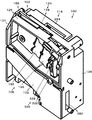
まず、投入口102を主に図1を参照して説明する。
投入口102は、識別されるべきコインCが投入される機能を有する。
通常、識別される複数のコインCのうち最大直径コインの直径よりも僅かに長く、最大厚みコインの厚みよりも僅かに厚い寸法に形成された矩形スリット形に形成される。
本実施例1において、投入口102は、縦向き矩形の本体124及び本体124に上端を回動自在に取り付けられたドアプレート126によって形成されている。
First, the
The
Usually, the plurality of coins C to be identified are formed in a rectangular slit shape that is slightly longer than the diameter of the maximum diameter coin and slightly thicker than the thickness of the maximum thickness coin.
In the first embodiment, the
まず本体124を主に図3を参照して説明する。
本体124は、縦横が3.5インチのデファクトスタンダード寸法に形成された大凡箱形の筐体であって、絶縁体、例えば樹脂によって成形されている。
本体124は、その両端部にT字形に左サイドプレート134及び右サイドプレート136が一体成形され、それらの間にほぼ垂立する平板状のベースプレート138が形成され、全体として平面視H形をしている。
したがって、本体124の正面側には、ベースプレート138を底とし、左サイドプレート134及び右サイドプレート136を側壁とする縦向きの装着溝142が形成される。
この装着溝142には、振分装置108、ドアプレート126、通路規制プレート128及びキャンセル通路カバ132等が配置される。
また、ベースプレート138の上端部はコイン通路104の一部を画定形成する。
すなわち、ベースプレート138の左上端部には投入口102を下向きにすぼまる漏斗状に構成するための、下向きの受入傾斜部140が形成されている。
First, the
The
The
Accordingly, a vertical mounting
In the mounting
Further, the upper end portion of the
That is, a downward receiving
次にドアプレート126を主に図5を参照して説明する。
ドアプレート126は、本体124と共同してコイン通路104を形成すると共にコインセンサ装置106の一部を保持し、さらに、コイン通路104においてジャムしたコインCを排除するため移動される機能を有する。
ドアプレート126は樹脂等の絶縁体によって大凡矩形に成形され、図4においてベースプレート138の右上部において右肩下がりの第1回転軸線RL1に沿って形成された円柱形の第1支軸144及び第2支軸146にその上端部形成した第1軸受孔148、第2軸受孔152を回動自在に嵌め合わせられ、その内側のドア案内壁154はベースプレート138の大凡上側半分に対し所定の間隔、すなわち最大コイン厚みよりも僅かに大きな間隔で平行に相対される。
また、ドアプレート126は、スプリング等の付勢装置(図示せず)によりベースプレート138に近づくように弾性的に付勢され、後述のガイドレール156の側端面を本体124のベースプレート138に突き当てることによりベースプレート138の上部案内壁162に対し前記間隔で平行に保持される。
ドアプレート126は、第1支軸144及び第2支軸146回りにその下端部がベースプレート138から離れるように回動された場合、上部案内壁162に対し下側程離れるよう回動される。これにより、コイン通路104においてジャムしたコインCが重力により落下可能になり、キャンセル通路118へ落下させ、最終的にリジェクト口282へキャンセルすることができる。
Next, the
The
The
Further, the
When the lower end portion of the
次に、投入口102をさらに詳細に説明する。
本実施例1において、投入口102は平面視横長矩形のスリット状であって、その長さは最も直径が大きい500円コインの直径よりも僅かに大きく、かつその幅は最も厚い500円コインの厚みよりも僅かに大きく形成されている。
ドアプレート126の左上部に下方に延在する投入凹溝158が形成され、ベースプレート138の受入傾斜部140と共同して、ベースプレート138の左上端部に投入口102が形成される。
よって、投入口102には1円〜500円コインを投入することができるが、1円及び5円コインは偽貨としてリジェクトされる。
Next, the
In the first embodiment, the
An input
Therefore, although 1 yen to 500 yen coins can be inserted into the
次にコイン通路104が主に図4を参照して説明される。
コイン通路104は、投入口102に投入されたコインCが転動する薄板状の通路であり、大凡S形に形成されている。
コイン通路104は、本体124のベースプレート138の上端部のほぼ垂立する上部案内壁162とドアプレート126の裏面のドア案内壁154との間に形成される。
ベースプレート上部案内壁162及びドア案内壁154は、転動するコインCがその面方向に傾いて転動するよう、コイン通路104がその一側面側に僅かに傾斜している。
コインCを上部案内壁162にもたれさせつつ転動させ、コインセンサ装置106に対するコインCの位置を安定させるためである。
ドア案内壁154の側部から下端部にかけて横向きに最厚コインの厚みよりも僅かに大きい幅でガイドレール156が突出形成されている。
Next, the
The
The
In the base plate
This is because the coin C is rolled while leaning against the
A
ドアプレート126のドア案内壁154は、下部のガイドレール156の側端面が上部案内壁162に当接した状態においてベースプレート138の上部案内壁162と平行になるように設定される。
図5におけるドアプレート126の左上端から下部にわたり、弧状のガイドレール156がドア案内壁154から横向きに突出形成されている。
ガイドレール156は投入口102からほぼ垂直下方に伸びる垂下部164、垂下部164に続いて横向きに転向させる転向部166、及び所定の角度で下向きに直線的に傾斜する傾斜部168より構成される。
本実施例1において、転向部166はコインCが衝撃的に落下するので、金属片により構成されている。
The
An arc-shaped
The
In the first embodiment, the turning
ガイドレール156の上面の転動面172は、ベースプレート138の上部案内壁162に対し直角に形成されている。
換言すれば、傾斜する上部案内壁162、及びそれに平行に配置されたドア案内壁154によって形成されるコイン通路104は、コインの面方向において上部案内壁162側へ僅かに傾斜しており、ガイドレール156上を転動するコインCは、上部案内壁162にもたれかかりつつ転動する。
また、ガイドレール156の上方のベースプレート138の上部案内壁162から横方向に突出し、かつ当該ガイドレール156と平行に上側ガイドレール174が形成されている。
ガイドレール156と上側ガイドレール174との間隔は、コインCのうち、最大径コインの500円コインの直径よりも僅かに大きく設定されている。
A rolling
In other words, the
Further, an
The interval between the
以上の説明から明らかなように、コイン通路104は、上部案内壁162、ドア案内壁154、ガイドレール156及び上側ガイドレール174により画定形成された垂線に対し僅かに傾斜され、かつ500円コインの厚みよりも僅かに厚い傾斜する薄板状の空間である。
また、コイン通路104は投入口102からほぼ垂直下方にコインCのほぼ直径分伸びる垂下通路176、垂下通路176に続いて横向き連続する転向通路178及び前下がりに直線的に傾斜する傾斜通路182により構成される。
換言すれば、コイン通路104は投入口102から下向きの弧状であり、全体としては前下がりの傾斜通路を構成する。
なお「前下がり」とは、コインの転動方向の前方に向かって下方という意味である。
As is apparent from the above description, the
Also, the
In other words, the
Note that the “downwardly forward” means downward toward the front in the coin rolling direction.
次にコインセンサ装置106が図2及び図4並びに図7〜10を参照して説明される。
コインセンサ装置106は、コイン通路104の傾斜通路182を転動するコインCの真贋及び金種を判別するための物理的特徴を検知する機能を有する。
コインセンサ装置106は、コイン通路104に相対してベースプレート138及びドアプレート126にそれぞれ固定された第1コインセンサ184及び第2コインセンサ186を含んでいる。
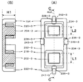
図8に示すように第1コインセンサ184は、コイン通路104を挟んで左右に配置された第1複合フェライト体188と第2複合フェライト体192によって構成されている。
第2コインセンサ186は、コイン通路104を挟んで左右に配置された第3複合フェライト体194と第4複合フェライト体196とによって構成されている。
第1複合フェライト体188、第2複合フェライト体192、第3複合フェライト体194及び第4複合フェライト体196は同一構成であるので、第1複合フェライト体188を代表してその構成を説明し、その他の複合フェライト体の同一部には同一符号を付し、末尾の「1」を「2」、「3」又は「4」に変更して付し、説明を省略する。
Next, the
The
The
As shown in FIG. 8, the
The
Since the first
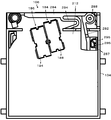
第1複合フェライト体188が図9を参照して説明される。
第1複合フェライト体188は、断面矩形であって、所定長さ(高さH1)の第1フェライトコア202-1と第2フェライトコア204-1とを有し、それら端面がコイン通路104に面するようベースプレート138の裏面に固定される。
第1フェライトコア202-1及び第2フェライトコア204-1の反コイン通路104側は、接続壁206-1によって接続されている。
第1フェライトコア202-1と第2フェライトコア204-1との周囲には矩形の磁束壁208-1が配置されている。
また、第1フェライトコア202-1、第2フェライトコア204-1及び接続壁206-1と磁束壁208-1との間も、第2接続壁212-1によって接続されている。
第1複合フェライト体188の形状を概括すれば、長方形鍋型の中央の鍋底部216-1から二つの角柱状の第1フェライトコア202-1及び第2フェライトコア204-1が突出している。
磁束壁208-1と第1フェライトコア202及び第2フェライトコア204の端面は同一平面内に位置している。
第1フェライトコア202-1及び第2フェライトコア204-1の周囲には、第1コイル218-1、第2コイル220-1が配置され、接着剤等により不動に固定されている。
The first
The first
The
A rectangular magnetic flux wall 208-1 is disposed around the first ferrite core 202-1 and the second ferrite core 204-1.
Further, the first ferrite core 202-1, the second ferrite core 204-1 and the connection wall 206-1 and the magnetic flux wall 208-1 are also connected by the second connection wall 212-1.
To summarize the shape of the first
The magnetic flux wall 208-1 and the end surfaces of the first ferrite core 202 and the second ferrite core 204 are located in the same plane.
A first coil 218-1 and a second coil 220-1 are arranged around the first ferrite core 202-1 and the second ferrite core 204-1 and are fixedly fixed by an adhesive or the like.
磁束壁208-1の第1短辺壁222-1及び対辺の第2短辺壁224-1の中間の中央には、所定の一定幅を有する第1短辺溝226-1、第2短辺溝228-1がそれぞれ形成されている。
磁束壁208-1の第1長辺壁232-1及び対辺の第2長辺壁234-1の中間には、第1長辺溝236-1、第2長辺溝238-1がそれぞれ形成されている。
第1短辺溝226-1、第2短辺溝228-1、第1長辺溝236-1及び第2長辺溝238-1は第1複合フェライト体188の位置決め及び第1コイル218-1、第2コイル220-1のリード線の配線に用いられる。
第1複合フェライト体188の長手方向中央に位置する第1軸線AL1はガイドレール156の傾斜部168に対し直角をなすように配置される。
第1軸線AL1は、第1短辺溝226-1及び第2短辺溝228-1の中央に位置する。
第1短辺溝226-1及び第2短辺溝228-1にはベースプレート138の裏面から突出する断面矩形の第1位置決め突起242-1、第2位置決め突起244-1が挿入され、第1長辺溝236-1及び第2長辺溝238-1には同様にベースプレート138の裏面から突出する断面矩形の第3位置決め突起243-1、第4位置決め突起245-1が挿入され、ガイドレール156に対する第1複合フェライト体188の位置決めがなされる。
In the middle of the first short side wall 222-1 and the second short side wall 224-1 on the opposite side of the magnetic flux wall 208-1, a first short side groove 226-1 having a predetermined constant width, a second short side wall Side grooves 228-1 are respectively formed.
A first long-side groove 236-1 and a second long-side groove 238-1 are respectively formed between the first long-side wall 232-1 and the second long-side wall 234-1 on the opposite side of the magnetic flux wall 208-1. Has been.
The first short-side groove 226-1, the second short-side groove 228-1, the first long-side groove 236-1 and the second long-side groove 238-1 are positioned for the first
The first axis AL1 located at the center in the longitudinal direction of the first
The first axis AL1 is located at the center of the first short side groove 226-1 and the second short side groove 228-1.
The first short-side groove 226-1 and the second short-side groove 228-1 are inserted with a first positioning protrusion 242-1 and a second positioning protrusion 244-1 having a rectangular cross section protruding from the back surface of the
第1複合フェライト体188において、ガイドレール156に対し遠い位置に位置する第1フェライトコア202-1の端面は、ガイドレール156に対し直角なす第1軸線AL1に沿ってL1の長さを有する。
ガイドレール156に対し近い位置に位置する第2フェライトコア204-1の端面は、ガイドレール156に対し直角をなす線AL1に沿ってL2の長さを有する。
長さL1は、長さL2よりも長い、換言すれば、第1フェライトコア202-1の第1軸線AL1に沿った長さL1は第2フェライトコア204-1の長さL2よりも長い、更に換言すれば、第1フェライトコア202-1の長さL1は第2フェライトコア204-1の長さL2とは異なる。
第1複合フェライト体188に相対してドアプレート126の裏面にも第2複合フェライト体192が固定されている。
In the first
The end face of the second ferrite core 204-1 located at a position close to the
The length L1 is longer than the length L2, in other words, the length L1 along the first axis AL1 of the first ferrite core 202-1 is longer than the length L2 of the second ferrite core 204-1. In other words, the length L1 of the first ferrite core 202-1 is different from the length L2 of the second ferrite core 204-1.
A second
次に第2コインセンサ186を図10を参照して説明する。
第2コインセンサ186は、第1コインセンサ184に対しコイン通路104との関係では下流側に隣接して配置されている。
第2コインセンサ186は第3複合フェライト体194及び第4複合フェライト体196を含んでいるので、ベースプレート138に固定されている第3複合フェライト体194を代表して説明する。
その第1フェライトコア202-3、及び第2フェライトコア204-3が第1軸線AL1と平行な、換言すれば、ガイドレール156に対し直角をなす第2軸線AL2上に配置され、かつ、第1コインセンサ184の第1フェライトコア202-1、及び第2フェライトコア204-1とは逆の位置関係には配置されている。換言すれば、第2コインセンサ186は、第1コインセンサ184と上下関係において逆向きに配置されている。
詳しくは、第2フェライトコア204-3がガイドレール156から遠い位置に、第1フェライトコア202-3がガイドレール156に近い位置に配置され、第5位置決め突起246-3が第2短辺溝228-3に、第6位置決め突起247-3が第1短辺溝226-3に嵌め合わされて位置決めされた上、ベースプレート138の裏面に固定されている。
Next, the
The
Since the
The first ferrite core 202-3 and the second ferrite core 204-3 are arranged on the second axis AL2 that is parallel to the first axis AL1, in other words, perpendicular to the
Specifically, the second ferrite core 204-3 is disposed at a position far from the
次に第1コインセンサ184と第2コインセンサ186との位置関係を図7を参照して説明する。
第1コインセンサ184の第1フェライトコア202-1の下端縁250-1は、ガイドレール156から第1距離D1離れた位置に配置され、第2コインセンサ186の第2フェライトコア204-3の下端縁250-3はガイドレール156から第2距離D2離れた位置に配置され、第1フェライトコア202-1の上端縁252-1は第1距離D1に長さL1を加えた距離D3離れた位置に、第2フェライトコア204-3の上端縁252-3は第2距離D2に長さL2を加えた距離D4離れた位置に配置されている。
そして、第4距離D4は、第1距離D1よりも第3長さL3分長い。
換言すれば、第1コインセンサ184の第1フェライトコア202-1の下端縁250-1は、第2コインセンサ186の第2フェライトコア204-3の上端縁252-3との関係においてガイドレール156からの距離が同一部分が所定の第3長さL3において存在する。
さらに換言すれば、第1コインセンサ184の第1フェライトコア202-1の下端部は、第2コインセンサ186の第2フェライトコア204-2の上端部とは第3長さL3においてオーバーラップしている。
その理由は、第1コインセンサ184の第1フェライトコア202-1の下端縁250-1と第2コインセンサ186の第2フェライトコア204-3の上端縁252-3とを常に接する位置に配置できる場合、第3長さL3のオーバーラップは、原理的に不要である。しかし、第1複合フェライト体188〜第4複合フェライト体196の製造バラツキ、及びそれらの本体124又はドアプレート126に対する組み付けバラツキにより常にそれらが接する位置に配置できるとは限らない。
そこで、この第3長さL3のオーバーラップ長さを設けることにより、第1コインセンサ184及び第2コインセンサ186とから漏れなくコインの直径に関する物理情報を取得できるようにして検知精度を高めるようにしている。
Next, the positional relationship between the
The fourth distance D4 is longer than the first distance D1 by the third length L3.
In other words, the
In other words, the lower end portion of the first ferrite core 202-1 of the
The reason is always in contact position with the
Therefore, by providing an overlap length of the third length L3, physical information on the coin diameter can be acquired without omission from the
また、第1コインセンサ184の第1フェライトコア202-1の上端縁252-1は最大コイン、本実施例1では500円コインの直径よりも所定の第4長さL4分ガイドレール156から離れていることが好ましい。大径コインLCよりも僅かに大きい偽貨FCを排除するための精度高い物理情報を取得できるからである。
第2コインセンサ186の第2フェライトコア204-3の下端縁250-3は最小コイン、本実施例1では50円コインの直径よりも所定の第5長さL5分、ガイドレール156に近いことが好ましい。小径コインSCよりも僅かに小さい偽貨FCを排除するための精度高い物理情報を取得できるからである。
上記説明から明らかなように、第1コインセンサ184の第1フェライトコア202-1の上端縁252-1と第2コインセンサ186の第2フェライトコア204-3の下端縁250-1は、ガイドレール156に対し平行に配置されている、換言すれば、上端縁252-1と下端縁250-1は、平行に配置されている。
Further, the upper edge 25 2 -1 of the first ferrite core 202-1 of the
The second bottom edge 25 0 of the ferrite core 204-3 of the second coin sensor 186 - 3 minimum coin, the fifth length L5 minutes given than the diameter of the
As is clear from the above description, the upper edge 25 2 -1 of the first ferrite core 202-1 of the
次に図11を参照して第1直径センサ254、厚みセンサ256、第2直径センサ258、及び材質センサ262を説明する。
まず第1直径センサ254を説明する。
第1直径センサ254は、大径コインLCの直径に関する物理情報を取得する機能を有する。
第1コインセンサ184を構成する第1複合フェライト体188の第1フェライトコア202-1に巻かれた第1コイル218-1及び第2複合フェライト体192の第1フェライトコア202-2に巻かれた第1コイル218-2とは、第1直径センサ254を構成する。
Next, the
First, the
The
The first coil 218-1 wound around the first ferrite core 202-1 of the first
次に厚みセンサ256を説明する。
厚みセンサ256は、コインCの厚みに関する物理情報を取得する機能を有する。
第1コインセンサ184を構成する第1複合フェライト体188の第2フェライトコア204-1に巻かれた第2コイル220-1及び第2複合フェライト体192の第2フェライトコア204-2に巻かれた第2コイル220-2は、厚みセンサ256を構成する。
したがって、厚みセンサ256は10円〜500円の全ての金種のコインCが相対する位置、即ち、第2フェライトコア204-1及び204-2の上側縁のガイドレール156からの距離は、50円コインの直径中心よりも近くに配置されている。
Next, the
The
Winding around the second coil 220-1 wound around the second ferrite core 204-1 of the first
Therefore, the
次に第2直径センサ258を説明する。
第2直径センサ258は、小径コインSCの直径に関する物理情報を取得する機能を有する。
第2コインセンサ186を構成する第3複合フェライト体194の第2フェライトコア204-3に巻かれた第2コイル220-3及び第4複合フェライト体196の第2フェライトコア204-4に巻かれた第2コイル220-4とは、第2直径センサ258を構成する。
第2フェライトコア204-3及び204-4の端面全面に、500円コインが相対し、10円、50円及び100円コインはその端面の一部に相対する。
Next, the
The
The second ferrite core 20 4 of the
The 500 yen coins face the entire end face of the second ferrite cores 204-3 and 204-4 , and the 10, 50, and 100 yen coins face a part of the end face.
次に材質センサ262を説明する。
材質センサ262は、コインCの材質に関する物理情報を取得する機能を有する。
第2コインセンサ186を構成する第3複合フェライト体194の第1フェライトコア202-3に巻かれた第1コイル218-3及び第4複合フェライト体196の第1フェライトコア202-4に巻かれた第1コイル218-4は、材質センサ262を構成する。
したがって、材質センサ262は10円〜500円の全ての金種のコインCが相対する位置、即ち、第1フェライトコア202-3及び202-4の上側縁のガイドレール156からの距離は、50円コインの直径よりも近くに配置されている。
Next, the
The
Thirdly first ferrite core 20 2 -4 first coil 218-3 and the fourth composite ferrite member 19 6 wound on the first ferrite core 202-3 of the
Therefore, the
最大直径の500円コインがガイドレール156を転動する場合、第1直径センサ254を構成する第1フェライトコア202-1及び202-2は、それらの上端縁252-1から長さL4分ガイドレール156に近い位置において500円コインの上端が相対する。これにより、後述するように後述の第1直径検波整流回路316-1からは図12に示すような、倒立放物曲線状の波形500d1を得ることができる。
When the 500-diameter coin with the maximum diameter rolls on the
第2直径センサ258を構成する第2フェライトコア204-3と204-4端面は、全面が500円コインに相対するので、後述の第2直径検波整流回路316-2からは図12に示すような、倒立台形状の波形500d2を得ることができる。
Since the end faces of the second ferrite cores 204-3 and 204-4 constituting the
厚みセンサ256は500円コインのほぼ中央部に配置されているので第2フェライトコア204-1及び204-2の全面がコインに相対するため、後述の厚み検波整流回路316-3からは図12に示すような、ほぼ倒立台形状の波形500t1を得ることができる。
Entire surface of the second ferrite cores 204-1 and 204-2 for facing to the coin because the
さらに、材質センサ262を構成する第1フェライトコア202-3及び204-4の全面と相対するので、材質検波整流回路316-4からは図12に示すような、倒立台形状の波形500mが得られる。
Furthermore, since it faces the entire surface of the first ferrite cores 202-3 and 204-4 constituting the
二番目に直径が大きい10円コインが投入された場合図13に示すように、第1直径センサ254から500円よりもレベルが低い倒立放物曲線状の波形10d1が、第2直径センサ258からは第2フェライトコア204-3と204-4に対しては全面が相対するので、500d2よりも幅が狭い倒立台形状の波形10d2が、厚みセンサ256の第2フェライトコア204-1及び204-2の全面がコインに相対するため、500t1よりも幅が狭い波形10t1が、材質センサ262を構成する第1フェライトコア202-3及び202-4の全面と相対するので倒立台形状であって波形500mよりもレベルが低い波形10mが得られる。
なお、500円コインのレベルよりも低いのは、10円コインは材質が銅であるからである。
When a 10-yen coin having the second largest diameter is inserted, as shown in FIG. 13, an inverted parabolic waveform 10d1 having a level lower than 500 yen from the
The reason why the level is lower than the level of 500 yen coins is that 10 yen coins are made of copper.
三番目に直径が大きい100円コインが投入された場合図14に示すように、500円よりもレベルが低い倒立放物曲線状の波形100d1が、第2直径センサ258からは第2フェライトコア204-3と204-4に対しては全面が相対するので、500d2よりも幅が狭い倒立台形状の波形100d2が、厚みセンサ256の第2フェライトコア204-1及び204-2の全面がコインに相対するため、500t1よりも幅が狭い波形100t1が得られ、材質センサ262を構成する第1フェライトコア202-3及び202-4の全面と相対するので倒立台形状であって波形500mよりもレベルが低い波形100mが得られる。
When a 100-yen coin having the third largest diameter is inserted, an inverted parabolic waveform 100d1 having a level lower than 500 yen is generated from the
最小の50円コインが投入された場合図15に示すように、第1直径センサ254を構成する第1フェライト202-1及び202-2とは相対しないので、極めてレベルが低い波形50d1が得られ、第2直径センサ258を構成する第2フェライトコア204-3と204-4に対しては上端縁と上周縁が一致するよう相対するので、倒立台形状の波形50d2を得ることができ、厚みセンサ256の第2フェライトコア204-1及び204-2の全面が相対するため、最も幅が狭い波形50t1が得られ、材質センサ262を構成する第1フェライトコア202-3及び202-4の全面と相対するので、倒立台形状であって最も幅が狭い波形50mがそれぞれ得られる。
よって、これら波形より得られるレベルを判別することによりコインの真偽判別及び金種判別を適切に行うことができる。
When the minimum 50 yen coin is inserted, as shown in FIG. 15, the first ferrite 202-1 and 202-2 constituting the
Therefore, by determining the level obtained from these waveforms, it is possible to appropriately determine the authenticity of the coin and the denomination.
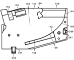
次に振分装置108が図4及び図6を参照して説明される。
振分装置108は、コインセンサ装置106によるコインCから取得した物理情報に基づいて判別した結果に基づいて当該コインCを正貨通路112又はリジェクト通路114へ振り分ける機能を有する。
コイン通路104のコインセンサ装置106の下流に位置するコイン通路下流端部104Eは、垂直下向きに指向した後、傾斜部168と逆向きの逆向き傾斜部264の入口部に位置している。
振分装置108は、コイン振分体266と第1電磁アクチュエータ268と第1リンク機構272を含んでいる。
Next, the
The
The coin passage downstream end 104E located downstream of the
The
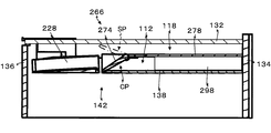
まずコイン振分体266を主に図4を参照して説明する。
コイン振分体266は、板状のフラップ274であって、後述の正貨通路112の延在方向に対し直交方向の第2回転軸線RL2を有する第1縦軸276を中心に回動可能である。
コイン振分体266は、逆向き傾斜部264を横断するキャンセル位置CP若しくは正貨通路112へ案内する収納位置SPに選択的に位置可能である。
コイン振分体266の第1縦軸276よりも下流側は左サイドプレート134と右サイドプレート136との間において垂直方向に位置する平板状のキャンセル壁278によって覆われている。
キャンセル壁278の上部と上部案内壁162とは、下向き斜面280によって接続されている。
第1縦軸276は、ベースプレート138に回動自在に軸支されている。
First, the
The
The
The downstream side of the
The upper part of the
First
次に第1リンク機構272を図4を参照して説明する。
第1リンク機構272は、第1電磁アクチュエータ268のソレノイドの励磁又は消磁によって、フラップ274をキャンセル位置CP又は収納位置SPに選択的に位置させるように駆動力を伝達する機能を有する。
第1電磁アクチュエータ268の鉄心(図示せず)は通常、スプリング(図示せず)により突出方向に付勢され、コイン振分体266は第1リンク機構272を介してキャンセル位置CPに保持される(図6の実線示位置)。
コイン振分体266がキャンセル位置CPに位置する場合、コイン通路104を転動してきたコインCは、コイン通路104を横断するコイン振分体266によって横方向に逸らされてキャンセル壁278に沿って落下し、逆向き傾斜部264から逸らされ、重力により落下する。
落下したコインCはリジェクト通路114を落下した後、リジェクト口282からゲーム機等の返却口(図示せず)へ案内される。
換言すれば、偽コイン、又はコイン識別装置100に電源が投入されていないときに投入されたコインは、リジェクトされる。
Next, the
The
The iron core (not shown) of the first
When the
The dropped coin C falls through the
In other words, a fake coin or a coin inserted when the
第1電磁アクチュエータ268が励磁された場合、鉄心が引き込まれ、フラップ274は第1リンク機構272を介して図6において時計方向に回動され、収納位置SPに移動される(図6の鎖線示位置)。
これにより、逆向き傾斜部264を転動してきたコインCはコイン振分体266に邪魔されることなく正貨通路112に進行できる。
正貨通路112を転動したコインCは、図示しない金庫に保留される。換言すれば、真正コインCは金庫に収納されることができる。
When the first
As a result, the coin C rolling on the reverse inclined
Coins C that have rolled in the
次に正貨通路112を図4及び図6を参照して説明する。
正貨通路112は、コイン振分体266により正貨として振り分けられたコインCが案内される機能を有する。
正貨通路112は、フラップ274の背面側に入口が配置され、キャンセル壁278とベースプレート138との間に形成され、本体下面に正貨口298が形成される。
正貨口298から落下したコインCは図示しない金庫に収納される。
Next, the
The
The
Coins C dropped from the
次にキャンセル装置116を図1及び図2を参照して説明する。
キャンセル装置116は、投入されたコインCがコイン通路104においてジャムした場合、右サイドプレート136の下部に開口されたリジェクト口282へ戻す機能を有する。
本実施例1において、キャンセル装置116は、ドアプレート126、キャンセルレバ284、及び、カム棒286を含んでいる。
Next, the cancel
The cancel
In the first embodiment, the cancel
まず、キャンセルレバ284を説明する。
キャンセルレバ284はL形であり、顧客がコインCをキャンセルするために操作するレバであり、本体124の上部背面から横方向に突出する固定軸288にその中間を回転自在に取り付けられている。
キャンセルレバ284の下方に伸びるレバ292は左サイドプレート134とほぼ平行に下向きに伸びている。
キャンセルレバ284は、顧客の操作によってリンク機構(図示せず)を介して押し下げ可能に配置されている。
また、キャンセルレバ284は中間から下方にZ形に伸びるスプリング294によって図2において時計方向に付勢力をうけているが、ほぼ水平位置において、図示しないストッパに係止されて静止状態に保持される。
First, the cancel
The cancel
A
The cancel
The cancel
次にカム棒286を説明する。
カム棒286はドアプレート126の背面側から前面側へベースプレート138の開口296を貫通して伸び、先端に斜面よりなるカム面287が形成されている。
キャンセルレバ284が図2において反時計方向に回動された場合、レバ292が同方向に回動すると、カム面287を押して横向きの力をカム棒286に与え、ドアプレート126の下端部をベースプレート138から離すように移動させる。
これにより、ガイドレール156と上部案内壁162との間の隙間が使用されるコイン中の最大厚み以上に開かれ、コイン通路104においてジャムしているコインC等は上部案内壁162に連続する下向き斜面280によって案内されてキャンセル通路118に落下させられ、キャンセルガイドレール302上を転動してリジェクト口282に案内される。
Next, the
If the cancel
As a result, the gap between the
次にキャンセル通路118を説明する。
キャンセル通路118は、偽貨FCと判別され、若しくはコイン識別装置100が判別状態にない状況においてコインCが投入された場合、当該偽貨FC又は投入コインCがコイン振分体266によってキャンセル壁278の表面側へ案内されたコインCをリジェクト口282にへ案内する機能を有する。
キャンセル通路118は、キャンセル壁278とキャンセル通路カバ132とにより構成される。
左サイドプレート134と右サイドプレート136の前側先端部間には、キャンセル壁278に対し最も厚いコインの厚みの数倍の間隔でキャンセル通路カバ132が垂立状体に取り付けられている。
これにより、キャンセル壁278とキャンセル通路カバ132との間には、垂立方向に延在するキャンセル通路118が形成される。
キャンセル通路118の下端は、リジェクト口282へ向かって下向きに傾斜するキャンセルガイドレール302が形成されている。
これにより、図3においてコイン振分体266によって紙面の表側へ案内された偽貨FC及びコインCはキャンセル通路118を落下した後、キャンセルガイドレール302上を転動してリジェクト口282に案内され、次いで返却口(図示せず)へ案内される。
Next, the cancel
When the coin C is inserted in the situation where the cancel
The
Between the front end portions of the
Accordingly, a cancel
A cancel
As a result, the fake coins FC and coins C guided to the front side of the page by the
次に検知装置120を図11を参照して説明する。
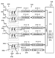
検知装置120は、第1直径センサ254、第2直径センサ258、厚みセンサ256、及び材質センサ262を構成する励磁コイル218-1、218-2、218-3、218-4、220-1、220-2、220-3、220-4からの信号(電流)を受けて制御装置122におけるコインの真偽及び金種判別のためのアナログ情報を出力する機能を有する。
検知装置120は、第1直径センサ254のための第1直径検知装置304、第2直径センサ258のための第2直径検知装置306、厚みセンサ256のための厚み検知装置308及び材質センサ262のための材質検知装置312を含んでいる。
Next, the
The
The
なお、図11において、コイル218及び220の巻き始めを、黒●で示している。
まず第1直径検知装置304を説明する。
第1直径検知装置304は、和動接続された第1複合フェライト体188の第1フェライトコア202-1に巻き付けられた第1コイル218-1と第2複合フェライト体192の第1フェライトコア202-2に巻き付けられた第1コイル218-2が接続された第1直径発振回路314-1、及び第1直径発振回路314-1からアナログ信号を受け、検波整流する第1検波整流回路316-1を含んでいる。
In FIG. 11, the winding start of the coil 21 8 and 2 20 are shown by black ●.
First, the
First
次に第2直径検知装置306を説明する。
第2直径検知装置306は、和動接続された第3複合フェライト体194の第2フェライトコア204-3に巻き付けられた第2コイル220-3と第4複合フェライト体196の第2フェライトコア204-4に巻き付けた第2コイル220-4が接続された第2直径発振回路314-2、及び第2直径発振回路314-2からアナログ信号を受け、検波整流した後、アナログ信号として出力する第2直径検波整流回路316-2を含んでいる。
Next, the
The second
次に厚み検知装置308を説明する。
厚み検知装置308は、差動接続された第1複合フェライト体188の第2フェライトコア204-1に巻き付けられた第2コイル220-1と第2複合フェライト体192の第2フェライトコア204-2に巻き付けられた第2コイル220-2とが接続された厚み発振回路314-3、及び厚み発振回路314-3から信号を受け、検波整流してアナログ信号を出力する厚み検波整流回路316-3を含んでいる。
Next, the
The
次に材質検知装置312を説明する。
材質検知装置312は、和動接続された第3複合フェライト体194の第1フェライトコア202-3に巻き付けられた第1コイル218-3と第4複合フェライト体196の第1フェライトコア202-4に巻きつけられた第1コイル218-4とが接続された材質発振回路314-4、及び材質発振回路314-4から信号を受け、検波整流した後アナログ信号として出力する材質検波整流回路316-4を含んでいる。
Next, the
The
第1直径発振回路314-1、第2直径発振回路314-2、厚み発振回路314-3及び材質発振回路314-4はそれぞれに適した異なる周波数の高周波電流を対応するコイルに印加する。
第1直径検波整流回路316-1、第2直径検波整流回路316-2、厚み検波整流回路316-3及び材質検波整流回路316-4は、対応する発振回路から受けた高周波電流を検波整流し、アナログ信号として出力する。
The first diameter oscillation circuit 314-1, the second diameter oscillation circuit 314-2, the thickness oscillation circuit 314-3, and the material oscillation circuit 314-4 apply high-frequency currents having different frequencies suitable for the respective coils.
The first diameter detection rectification circuit 316-1, the second diameter detection rectification circuit 316-2, the thickness detection rectification circuit 316-3 and the material detection rectification circuit 316-4 detect and rectify the high-frequency current received from the corresponding oscillation circuit. And output as an analog signal.
次に制御装置122が説明される。
制御装置122は、コインセンサ装置106によって取得したコインCの物理情報に基づいて、コインCの真偽及び金種識別を行い、当該真偽及び金種情報に基づいて第1電磁アクチュエータ268を選択的に作動させ、正貨であって、かつ受けいれるべき金種のコインを受け入れ、偽貨FC及び受け入れないコインをリジェクトする機能を有する。
制御装置122は、マイクロプロセッサ318、A/D変換回路320、ROM322、RAM324を含んでいる。
Next, the
The
The
A/D変換回路320は、第1直径検波整流回路316-1、第2直径検波整流回路316-2、厚み検波整流回路316-3、及び材質検波整流回路316-4のアナログ出力をデジタル情報に変換する機能を有する。
マイクロプロセッサ318は、ROM322に格納された所定のプログラムに基づいて所定の処理によりコインの真偽判別及び金種を識別し、当該識別結果に基づいて第1電磁アクチュエータ268を選択的に励磁又は消磁する。
具体的には、制御装置122は、偽貨FCを検知した場合、第1電磁アクチュエータ268を励磁しない。よって、フラップ274はキャンセル位置CPに保持されるので、コインCはキャンセル通路118へ案内されてキャンセルガイドレール302上を転動してリジェクト口282から返却口へ返却される。
コインCが正貨であり、かつ受け入れるべきコインである場合、第1電磁アクチュエータ268は所定時間励磁され、フラップ274が回動されて収納位置SPに位置するので正貨通路112に誘導される。
The A /
The
Specifically, the
When the coin C is a genuine coin and a coin to be received, the first
なお、投入口102には例えば自動販売機の筐体表面に配置したコイン投入口に投入されたコイン等をシュートにより案内することができる。
また、逆向き傾斜部264に糸吊り防止手段326を配置することが好ましい。
本実施例1の糸吊り防止手段326は、ドアプレート126に横向きに配置した支軸328に対し揺動可能に取り付けた阻止体332である。
通常、重力により阻止体332は支軸328を支点にその下端部が逆向き傾斜部264に進行するようモーメントが作用している。
これにより、阻止体332の下端先端はドア案内壁154の切り欠き334を通って上部案内壁162に当接した状態で静止している。
換言すれば、阻止体332の下端部が逆向き傾斜部264を横断している。
阻止体332の下端部上面は上部案内壁162に向かって下向きに傾斜している。
Note that, for example, a coin inserted into a coin insertion slot disposed on the surface of the casing of the vending machine can be guided to the
Further, it is preferable to dispose the thread suspension preventing means 326 on the reversely
The yarn suspension preventing means 326 of the first embodiment is a blocking
Normally, the moment acts so that the lower end of the blocking
As a result, the lower end tip of the blocking
In other words, the lower end portion of the blocking
The upper surface of the lower end portion of the blocking
よって、コインCが逆向き傾斜部264を通過する場合、阻止体332は当該コインCにより斜面を押されて移動され、当該コインCはこれを通過することが出来る。
コインCが通過した後、阻止体332は自己モーメントにより元に戻る。
これにより、糸吊りしたコインCを引き上げた場合、当該コインCによって阻止体332の下向き斜面が押され、阻止体332は上部案内壁162に押し付けられる。
よって、コインCは阻止体332に移動を阻止され、引き上げられない。
Therefore, when the coin C passes through the backward
After the coin C passes, the blocking
As a result, when the coin C suspended from the thread is pulled up, the downward slope of the blocking
Therefore, the coin C is prevented from moving by the blocking
次に本実施例1の作用を説明する。
まず真正コインCを投入したケースを説明する。
コイン識別装置100がスタンバイ状態にない場合、換言すれば、制御装置122に通電されていない場合、第1電磁アクチュエータ268は作動されることがない。よって、フラップ274はキャンセル位置CPを保持するので、真正コインCであってもリジェクト通路114に案内され、リジェクト口282から排除される。
当然、この状態において、偽貨FCを投入した場合、当該偽貨FCは真正コインCと同様に排除される。
Next, the operation of the first embodiment will be described.
First, a case where a genuine coin C is inserted will be described.
When the
Naturally, in this state, when the false coin FC is inserted, the false coin FC is excluded in the same manner as the genuine coin C.
コイン識別装置100がスタンバイ状態にある場合、第1電磁アクチュエータ268は消磁を継続し、その鉄心はスプリング(図示せず)によって突出され、第1リンク機構272を介してコイン振分体266、したがってフラップ274が図6における実線示のキャンセル位置CPに保持される。
When the
この状態で真正コインCが投入口102に投入された場合、真正コインCは垂下通路176をほぼ直径分垂直落下した後、ガイドレール156上を図4において右方へ転動する。
この転動過程において、コインCは第1コインセンサ184、第2コインセンサ186に順次相対し、当該コインCの直径、材質及び厚みに関する物理的特徴情報が取得される。
When the genuine coin C is inserted into the
In this rolling process, the coin C is sequentially opposed to the
例えば、最大直径コインである真正500円コインを投入した場合、図12に示すように、第1直径検出装置304に係る第1直径検波整流回路316-1の出力は波形500d1に示すように倒立放物曲線状になり、第2直径検出装置306に係る第2直径検波整流回路316-2の出力は波形500d2に示すように波形500d1に対し所定時間遅れた倒立台形状になり、厚み検知装置308に係る厚み検波整流回路316-3の出力は波形500d1と同時期に波形500t1に示すように倒立台形状になり、及び材質検知装置312に係る材質検波整流回路316-4の出力は波形500d2と同時期に波形500mに示すように倒立足つき台形状になる。
これらの波形で出力されるアナログ信号は、A/D変換回路320によってそれぞれデジタル信号化され、ROM322に記憶された所定のプログラムによって真偽判別及び金種判別がされる。
上記判別は、大凡各波形500d1、500d2、500t1及び500mのピーク値500Pd1、500Pd2、500Pt1及び500Pmを求め、それらピーク値を基準値と比較することにより行われる。
For example, when a genuine 500 yen coin, which is the maximum diameter coin, is inserted, as shown in FIG. 12, the output of the first diameter detection rectifier circuit 316-1 related to the first
Analog signals output by these waveforms are respectively a digital signal by the A / D converter circuit 32 0 is the authenticity determination and the denomination determined by a predetermined program stored in the
The above determination is roughly determined each waveform 500D1,500d2,
本例では真正500円コインと判別され、第1電磁アクチュエータ268が所定時間励磁され、フラップ274は収納位置SPに回動される。これにより、真正500円コインCはフラップ274によって正貨通路112へ案内され、正貨口298から金庫へ落下する。
偽コインFCである場合、制御装置122は偽コイン信号FSを出力する。
偽コイン信号FSに基づいて、第1電磁アクチュエータ268は励磁されないのでフラップ274はリジェクト位置CPのままである。よって、偽コインFCはリジェクト通路114へリジェクトされ、リジェクト口282を経由して返却される。
In this example, a genuine 500 yen coin is determined, the first
If it is a fake coin FC, the
Based on the false coin signal FS, the first
真正10円コインを投入した場合、図13に示すように、各波形10d1、10d2、10t1及び10mのピーク値10Pd1、10Pd2、10Pt1及び10Pmを求め、各基準値と比較することにより行われる。
When a genuine 10 yen coin is inserted, as shown in FIG. 13, peak values 10Pd1, 10Pd2,
真正100円コインを投入した場合、図14に示すように、各波形100d1、100d2、100t1及び100mのピーク値100Pd1、100Pd2、100Pt1及び100Pmを求め、各基準値と比較することにより行われる。
When a genuine 100 yen coin is inserted, as shown in FIG. 14, peak values 100Pd1, 100Pd2,
最小直径コインである真正50円コインを投入した場合、図15に示すように、各波形50d1、50d2、50t1及び50mのピーク値50Pd1、50Pd2、50Pt1及び50Pmを求め、各基準値と比較することにより行われる。
本例の場合、真正50円コインであるので、前述のようにフラップ274によって正貨通路112へ案内され、正貨口298から金庫へ落下する。
偽コインFCである場合、前述同様にリジェクト通路114へリジェクトされる。
When a genuine 50 yen coin, which is the smallest diameter coin, is inserted, the peak values 50Pd1, 50Pd2,
In the case of this example, since it is a genuine 50 yen coin, it is guided to the
If it is a fake coin FC, it is rejected to the
実施例1は、第1コインセンサ184の大径コインLCの選別用に長さL1を有する第1フェライトコア202-1及び202-2により構成し、小径コインSCの選別用に長さL1よりも短い長さL2を有する第2フェライトコア204-3及び204-4との組み合わせにより日本円の10円、50円、100円及び500円に最も適したコインセンサ装置106を構成した例である。
The first embodiment is configured by first ferrite cores 202-1 and 202-2 having a length L1 for sorting the large coin LC of the
次に、図16を参照して第1コインセンサ184及び第2コインセンサ186の両方とも長さL1を有する第1フェライトコア202-1、202-2及び202-3、202-4によって構成したケースを説明する。
第2長さL2、第3長さL3、及び第5長さL5を同一にした場合、第2コインセンサ186の第1フェライトコア202-3、202-4の長さは、第2フェライトコア204-3、204-4よりも長い。
結果として、第2直径検知装置306の下端縁250-3が長さL6分長くなる。
これにより、小径コインSCのための第2直径検知装置306の感度が実施例1のコインセンサ装置106に対して鈍る。
換言すれば、同一条件下において、第2フェライトコア204-3、204-4が採用されている場合に比し、図16(B)に示す程度に感度が低下する。これにより、判断の基準レベルを従来のように上げる(高める)ことができない。よって、判別精度が低下する恐れがある。
しかし、本願発明においては、第1フェライトコア202-1の長さL1及び/又は第2フェライトコア204-1の長さL2を適宜組み合わせて、選別対象コインの直径に適切なフェライトコア端面の長さを得ることができる。よって、精度高い直径選別を行うことが出来る。
Next, referring to FIG. 16, both the
When the second length L2, the third length L3, and the fifth length L5 are the same, the length of the first ferrite cores 202-3 and 202-4 of the
As a result, the lower edge 25 0 of the second diameter sensing device 306 - 3 is the length L6 minutes longer.
Thereby, the sensitivity of the second
In other words, the sensitivity is reduced to the extent shown in FIG. 16 (B) as compared with the case where the second ferrite cores 204-3 and 204-4 are employed under the same conditions. As a result, it is not possible to raise (increase) the reference level of judgment as in the prior art. Therefore, there is a risk that the discrimination accuracy is lowered.
However, in the present invention, the length L1 of the first ferrite core 202-1 and / or the length L2 of the second ferrite core 204-1 are appropriately combined, and the length of the ferrite core end face appropriate for the diameter of the coin to be selected is selected. You can get it. Therefore, it is possible to perform diameter selection with high accuracy.
次に実施例2を図17を参照して説明する。
実施例1と同一部には同一符号を付して説明を省略し、異なる部位を説明する。
実施例1と実施例2の相違点は、第1コインセンサ184とガイドレール156との間の第1軸線AL1上に第2厚みセンサ342が配置されている点である。
第2厚みセンサ342は、ガイドレール156に近接配置されるので、コインCの周縁部の厚みに関する物理情報を取得するのに適している。
換言すれば、第1厚みセンサ256はコインCの中央部の厚みに関する物理情報を取得し、第2厚みセンサ342はコインCの周縁部の厚みに関する物理情報を取得するのに適している。
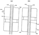
さらに換言すれば、図17(B)に示すように、周縁リング344に異なる材質の円板形のコア346を嵌め込んだバイメタルコインBCの精度高い真偽判別に適している。
Next, Example 2 will be described with reference to FIG.
The same parts as those in the first embodiment are denoted by the same reference numerals, description thereof is omitted, and different parts are described.
The difference between the first embodiment and the second embodiment is that a
Since the
In other words, the
In other words, as shown in FIG. 17B, it is suitable for highly accurate authenticity determination of a bimetal coin BC in which a disc-shaped
第2厚みセンサ342の構成を図11をも参照して説明する。
実施例1と同一部分には同一符号を付し、異なる構成を説明する。
ガイドレール156と第1コインセンサ184との間に第2厚み検知装置348が配置されている。
第2厚み検知装置348は、コイン通路104に相対したベースプレート138の背面に固定された第1円形フェライトコア体352-1、及び、ドアプレート126の背面に固定された第2円形フェライトコア体352-2(第1円形フェライトコア体352-1と同一につき図示省略)を含んでいる。
第1円形フェライトコア体352-1の中心には円柱状の第1円形フェライトコア354-1が形成され、第1円形フェライトコア354-1と同心であってその外周にドーナツリング状に形成された第1磁束壁356-1とは第1接続壁358-1を介して接続された、所謂ポットコア型である。
第1円形フェライトコア354-1の周囲には第1コイル362-1が巻き付けられている。第2円形フェライトコア体352-2の第2コイル362-2とは差動接続され、第2厚み発振回路314-5に接続されている。
第1円形フェライトコア354-1は、その端面中心がガイドレール156と第1コインセンサ184との間の第1軸線AL1上であって、ガイドレール156に近接した位置に配置されている。
The configuration of the
The same parts as those in the first embodiment are denoted by the same reference numerals, and different configurations will be described.
A
The second
A cylindrical first circular ferrite core 354-1 is formed at the center of the first circular ferrite core body 352-1 and is concentric with the first circular ferrite core 354-1 and formed in a donut ring shape on the outer periphery thereof. and the first magnetic flux wall 356-1 is connected via a first connecting wall 358 -1, a so-called pot core.
A first coil 362-1 is wound around the first circular ferrite core 354-1. The second coil 362-2 of the second circular ferrite core body 352-2 is differentially connected to the second thickness oscillation circuit 314-5.
The center of the end surface of the first circular ferrite core 354-1 is on the first axis AL1 between the
第2厚み発振回路314-5は、各発振回路314-1〜314-4とは異なる周波数にて発振し、第2厚み検波整流回路316-5にアナログ信号を出力する。
第2厚み検波整流回路316-5は、検波整流した信号をA/D変換回路320に出力する。A/D変換回路320は前述同様に第2厚み検波整流回路316-5からのアナログ信号をデジタル信号に変換してマイクロプロセッサ318の処理に供する。
The second thickness oscillation circuit 314-5 oscillates at a frequency different from that of the oscillation circuits 314-1 to 314-4, and outputs an analog signal to the second thickness detection rectification circuit 316-5.
Second thickness detection rectification circuit 316-5 outputs the detected and rectified signal to A /
実施例2において、500円コインを投入した場合、実施例1と同様に図18に示すように第1直径センサ254、第2直径センサ258、厚みセンサ256、材質センサ262にて取得した物理情報に基づいて第1直径検波整流回路316-1、第2直径検波整流回路316-2、厚み検波整流回路316-3及び材質検波整流回路316-4から金種に対応した波形500d1、500d2、500t1及び500mが出力される。
同時に、第2厚みセンサ342によって取得した物理情報に基づいて第2厚み検波整流回路316-5から波形500t2の信号が出力される。
マイクロプロセッサ318において、これら波形500d1、500d2、500t1、500m及び500t2のピーク値500Pd1、5500Pd2、500Pt1、500Pm及び500Pt2を求め、基準値と比較することにより、総合的に真偽判別及び真正コインである場合、金種判別を行う。
真正コインである場合、第1電磁アクチュエータ268が所定のタイミングで所定時間励磁され、正貨通路112へ受け入れられる。偽貨FCである場合、第1電磁アクチュエータ268は励磁されないので、当該偽貨FCはリジェクト通路114へ案内され、返却口へ戻される。
実施例2は、厚みセンサが2つであるので、バイメタルコインBCの選別に適している。
In Example 2, when 500 yen coins are inserted, the physical information acquired by the
At the same time, based on the physical information acquired by the
In the
When the coin is a genuine coin, the first
Since the second embodiment has two thickness sensors, it is suitable for sorting the bimetal coin BC.
次に実施例3を図19を参照して説明する。
実施例3は、実施例2の第2厚みセンサ342が第1八角フェライトコア体364-1及び同一形状の第2八角フェライトコア体364-2とにより構成される点が異なる。
第1八角フェライトコア体364-1及び同一形状の第2八角フェライトコア体364-2は同一構成なので、第1八角フェライトコア体364-1を代表して説明する。
第1フェライトコア366-1の端面は円筒形であり、第1磁束壁368-1は、外縁が横向き山形であって、内側縁が弧状に形成され、かつ、第1フェライトコア366-1の横方向の両側に配置され、第1コインセンサ184側には配置されない。
Next, Example 3 will be described with reference to FIG.
Example 3 is composed of point differs by a second eight corner ferrite core body 364-2 of the
The second eight corner ferrite core body 364-2 of first eight corner ferrite core bodies 364-1 and the same shape since the same configuration will be described as a representative first eight corner ferrite core body 364-1.
The end surface of the first ferrite core 366-1 is cylindrical, and the first magnetic flux wall 368-1 has a laterally mountain-shaped outer edge, an inner edge formed in an arc shape, and the first ferrite core 366-1. It is arranged on both sides in the horizontal direction and is not arranged on the
実施例3は、基本的には実施例2と同様にコインCを識別し、処理する。
しかし、第1八角フェライトコア体364-1及び第2八角フェライトコア体364-2は、第1コインセンサ184側に磁束壁368-1及び368-2は配置されない。
第1フェライトコア366-1には第1励磁コイル370-1が巻き付けられている。
したがって、ガイドレール156と第1コインセンサ184との間に配置される第1フェライトコア366-1の直径を大きくすることができる。換言すれば、第1フェライトコア366-1端面の面積を実施例2の第1フェライトコア354-1の端面の面積よりも大きくすることができる。
第2厚みセンサ342の第1フェライトコア366-1端面の面積が大きい場合、磁束をより遠くまで波及させることができる。
よって、選別するコインCの厚み差が大きい場合、換言すれば、コイン通路104の厚みが厚い場合にも、精度高いコイン厚みに関する物理情報を取得できるので、厚みの選別精度が高まる利点がある。
実施例3も厚みセンサが2つであるので、バイメタルコインBCの選別に適している。
The third embodiment basically identifies and processes the coin C as in the second embodiment.
However, the first eight corner ferrite core bodies 364-1 and the second eight corner ferrite core member 364-2 is magnetic flux walls 368-1 and 368-2 to the
A first exciting coil 370-1 is wound around the first ferrite core 366-1.
Therefore, the diameter of the first ferrite core 366-1 disposed between the
When the area of the end face of the first ferrite core 366-1 of the
Therefore, when the thickness difference of coins C to be sorted is large, in other words, even when the thickness of the
Since the third embodiment also has two thickness sensors, it is suitable for sorting the bimetal coin BC.
次に実施例4を図20を参照して説明する。
実施例4は、第1コインセンサ184に第1直径センサ254を構成する端面矩形の第1フェライトコア202-1、厚みセンサ256のための第2フェライトコア204-1及び第2厚みセンサ342のための端面矩形の第2厚みフェライトコア368-1が接続壁206-1によって接続され、また磁束壁208-1で囲われたフェライトコア体372に一体に形成されている。
第1フェライトコア202-1、第2フェライトコア204-1及び第2厚みフェライトコア368-1の第1軸線AL1に沿った長さは同一長さL1に形成されている。同一長さL1にすることにより、成形型の製造が容易になり、安価に製造することができる。
第2コインセンサ186の第2フェライトコア204-3と第1コインセンサ184の第1フェライトコア202-1とのオーバーラップ長L3等は実施例1と同一に設定してある。
第1フェライトコア202-1、第2フェライトコア204-1及び第2厚みフェライトコア368-1には、それぞれ個別に矩形の励磁コイル370-1、370-2、370-3が巻き付けられている。
実施例4も厚みセンサが2つであるので、バイメタルコインBCの選別に適している。
Next, Example 4 will be described with reference to FIG.
In the fourth embodiment, the
The lengths of the first ferrite core 202-1, the second ferrite core 204-1 and the second thickness ferrite core 368-1 along the first axis AL1 are formed to have the same length L1. By using the same length L1, the mold can be easily manufactured and can be manufactured at low cost.
The overlap length L3 between the second ferrite core 204-3 of the
Rectangular excitation coils 370-1, 370-2, and 370-3 are individually wound around the first ferrite core 202-1, the second ferrite core 204-1, and the second thickness ferrite core 368-1, respectively. .
Since Example 4 also has two thickness sensors, it is suitable for sorting the bimetal coin BC.
実施例4において、第2厚みセンサ342の第2厚みフェライトコア364-1と厚みフェライトコア204-1との間に磁束壁208-1が配置されないので、第2厚みフェライトコア364-1の面積を大きくでき、厚みの選別精度が向上する。
さらに、フェライトコア体372に第1直径センサ254、厚みセンサ256及び第2厚みセンサ342が一体に構成されているので、材料や工程を節約でき、安価に製造することができる。また、センサを小型化できる利点がある。
In Example 4, since the magnetic flux wall 208-1 is not disposed between the second thickness ferrite core 36 4 -1 and the thickness ferrite core 204-1 of the
Furthermore, since the
Claims (1)
前記複数のフェライトコアのうち、前記コインの転動方向上流側に位置する前記フェライトコアの端面と前記コインの転動方向下流側に位置する前記フェライトコアの端面とを前記転動面に対して直角な方向にずらして配置したコイン識別装置において、Out of the plurality of ferrite cores, an end face of the ferrite core located on the upstream side in the rolling direction of the coin and an end face of the ferrite core located on the downstream side in the rolling direction of the coin with respect to the rolling face In the coin identification device that is shifted in a perpendicular direction,
前記転動面に対し直角方向に延在し且つ前記コインの転動方向上流側に位置する第1軸線上及び前記コインの転動方向下流側に位置する第2軸線上のそれぞれに一対の前記フェライトコアの端面が配置され、前記一対のフェライトコアはいずれも接続壁によって連結されて一体化されると共に、前記一対のフェライトコアのうちの前記ガイドレールの転動面から遠い一方のフェライトコアの端面から前記ガイドレールまでの距離が前記第1軸線上に配置された前記フェライトコアと前記第2軸線上に配置された前記フェライトコアとで異なることを特徴とするコイン識別装置。A pair of each of the first axis extending on the upstream side in the rolling direction of the coin and the second axis positioned on the downstream side in the rolling direction of the coin extends in a direction perpendicular to the rolling surface. An end face of the ferrite core is arranged, and the pair of ferrite cores are connected and integrated by a connection wall, and one of the ferrite cores far from the rolling surface of the guide rail of the pair of ferrite cores. A coin identifying device, wherein a distance from an end surface to the guide rail is different between the ferrite core disposed on the first axis and the ferrite core disposed on the second axis.
Priority Applications (1)
| Application Number | Priority Date | Filing Date | Title |
|---|---|---|---|
| JP2010157196A JP5608898B2 (en) | 2010-07-09 | 2010-07-09 | Coin identification device |
Applications Claiming Priority (1)
| Application Number | Priority Date | Filing Date | Title |
|---|---|---|---|
| JP2010157196A JP5608898B2 (en) | 2010-07-09 | 2010-07-09 | Coin identification device |
Related Child Applications (1)
| Application Number | Title | Priority Date | Filing Date |
|---|---|---|---|
| JP2014147323A Division JP2014197429A (en) | 2014-07-18 | 2014-07-18 | Coin identification device |
Publications (3)
| Publication Number | Publication Date |
|---|---|
| JP2012018638A JP2012018638A (en) | 2012-01-26 |
| JP2012018638A5 true JP2012018638A5 (en) | 2013-08-15 |
| JP5608898B2 JP5608898B2 (en) | 2014-10-22 |
Family
ID=45603825
Family Applications (1)
| Application Number | Title | Priority Date | Filing Date |
|---|---|---|---|
| JP2010157196A Active JP5608898B2 (en) | 2010-07-09 | 2010-07-09 | Coin identification device |
Country Status (1)
| Country | Link |
|---|---|
| JP (1) | JP5608898B2 (en) |
Family Cites Families (3)
| Publication number | Priority date | Publication date | Assignee | Title |
|---|---|---|---|---|
| DE10140225C2 (en) * | 2001-08-16 | 2003-08-07 | Nat Rejectors Gmbh | Method and device for measuring the diameter of coins |
| JP4022583B2 (en) * | 2002-03-11 | 2007-12-19 | 旭精工株式会社 | Coin selector |
| JP5167470B2 (en) * | 2006-06-30 | 2013-03-21 | 旭精工株式会社 | Coin identification device for coin identification sensor and coin selector |
-
2010
- 2010-07-09 JP JP2010157196A patent/JP5608898B2/en active Active
Similar Documents
| Publication | Publication Date | Title |
|---|---|---|
| CA1275475C (en) | Tokens and apparatus for handling tokens | |
| JP2767278B2 (en) | Coin sorting equipment | |
| JP5167470B2 (en) | Coin identification device for coin identification sensor and coin selector | |
| US8210337B2 (en) | Method and sensor for sensing coins for valuation | |
| JP2008009894A5 (en) | ||
| JP5261655B2 (en) | Value medium processing device | |
| US11205315B2 (en) | Magnetism detection device, coin recognition device, and method for detecting magnetism using magnetism detection device | |
| JP2009193375A5 (en) | ||
| JP5608898B2 (en) | Coin identification device | |
| JP5564734B2 (en) | Coin hopper | |
| JP2012018638A5 (en) | ||
| JP2014197429A (en) | Coin identification device | |
| US6441891B1 (en) | System for detecting a foreign object attached to a bill passing through a bill validator | |
| JPH08212416A (en) | Coin discriminating device | |
| JP5119421B2 (en) | Coin selector | |
| JP4453221B2 (en) | Money handling machine | |
| JP4431732B2 (en) | Coin selector | |
| JP2006048509A (en) | Coin selector | |
| TWM653292U (en) | Coin accepting device | |
| JP3192785B2 (en) | Coin identification device | |
| JPH0363780B2 (en) | ||
| JP2008027277A (en) | Object discrimination device | |
| JP2017220118A (en) | Coin identification device and coin identification method | |
| JP2008047009A5 (en) | ||
| JP2002123854A (en) | Coin discriminating device and magnetic sensor body |