JP2012012131A - Jamming eliminating mechanism and inspecting device - Google Patents

Jamming eliminating mechanism and inspecting device Download PDF

Info

Publication number
JP2012012131A
JP2012012131A JP2010147930A JP2010147930A JP2012012131A JP 2012012131 A JP2012012131 A JP 2012012131A JP 2010147930 A JP2010147930 A JP 2010147930A JP 2010147930 A JP2010147930 A JP 2010147930A JP 2012012131 A JP2012012131 A JP 2012012131A
Authority
JP
Japan
Prior art keywords
guide
width
alignment
clogging
tablet
Prior art date
Legal status (The legal status is an assumption and is not a legal conclusion. Google has not performed a legal analysis and makes no representation as to the accuracy of the status listed.)
Granted
Application number
JP2010147930A
Other languages
Japanese (ja)
Other versions
JP5551982B2 (en
Inventor
Akio Sato
章雄 佐藤
Current Assignee (The listed assignees may be inaccurate. Google has not performed a legal analysis and makes no representation or warranty as to the accuracy of the list.)
Ikegami Tsushinki Co Ltd
Original Assignee
Ikegami Tsushinki Co Ltd
Priority date (The priority date is an assumption and is not a legal conclusion. Google has not performed a legal analysis and makes no representation as to the accuracy of the date listed.)
Filing date
Publication date
Application filed by Ikegami Tsushinki Co Ltd filed Critical Ikegami Tsushinki Co Ltd
Priority to JP2010147930A priority Critical patent/JP5551982B2/en
Publication of JP2012012131A publication Critical patent/JP2012012131A/en
Application granted granted Critical
Publication of JP5551982B2 publication Critical patent/JP5551982B2/en
Active legal-status Critical Current
Anticipated expiration legal-status Critical

Links

Images

Abstract

PROBLEM TO BE SOLVED: To provide an inspecting device for small articles which includes a jamming eliminating mechanism capable of eliminating jamming when small articles are conveyed at high speed, and are jammed, and achieves improvement in prescribed alignment capacity.SOLUTION: When jamming of tablets T occurs, a width regulation guide 42a is moved to widen a first conveyance path for alignment 10a in width, whereby the tablets being a cause of jamming and the tablets delayed in conveyance are dropped to a tablet collecting box 84 to be collected.

Description

本発明は、煩雑な状態で送られてくる錠剤等の小物物品を所定の姿勢で整列させて検査を行う小物物品の検査装置に関し、特に、検査装置に用いられる、小物物品の搬送中の詰まりを除去することが可能な詰まり除去機構および小物物品の検査装置に関する。   The present invention relates to an inspection apparatus for small articles in which small articles such as tablets that are sent in a complicated state are aligned in a predetermined posture and inspected, and in particular, clogging during transportation of small articles used in the inspection apparatus. The present invention relates to a clogging removal mechanism and an inspection device for small articles that can remove the spill.

錠剤等の小物物品の整列搬送装置として、出願人は、特許文献1や特許文献2に示されるような平坦な搬送路と側面ガイドを利用して高速搬送を可能とする整列搬送装置を既に提案してきている。   As an apparatus for aligning and conveying small articles such as tablets, the applicant has already proposed an aligning and conveying apparatus that enables high-speed conveyance using a flat conveyance path and side guides as shown in Patent Document 1 and Patent Document 2. Have been doing.

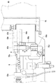
図7は、特許文献2に提案されている小物物品の整列搬送装置の一部を示した部分拡大概略図である。整列搬送装置は、概略、搬送ベルト111上に画定される錠剤Tを整列搬送する搬送路110、搬送ベルト111に乗って移動する錠剤Tを整列させる搬送路110を画定するガイド部材120、同じく搬送路110を画定する部材であって、高さを規制するゲート部材(不図示)、同じく搬送路110を画定する部材であって、幅を規制するゲート部材を構成する幅規制ガイド130、及び搬送路110から振分、排除された錠剤を整列搬送装置の上流の戻すための還元用搬送路140を備えている。   FIG. 7 is a partially enlarged schematic view showing a part of an accessory conveying and conveying apparatus proposed in Patent Document 2. In FIG. The aligning and conveying apparatus generally includes a conveying path 110 for aligning and conveying tablets T defined on the conveying belt 111, a guide member 120 for defining a conveying path 110 for aligning tablets T moving on the conveying belt 111, and also conveying the same. A gate member (not shown) that defines the path 110 and that regulates the height, a member that also defines the transport path 110 and that constitutes the gate member that regulates the width, and the transport A return conveyance path 140 is provided for returning the tablets distributed and removed from the path 110 to the upstream side of the alignment conveyance apparatus.

ガイド部材120は、具体的には搬送における上流において、搬送ベルト111上を斜めに遮るように横断し、整列用搬送路110を次第に狭めるように画定し(不図示)、下流において、幅規制ガイド130との間に錠剤Tが一列に整列して搬送されるように整列用搬送路110を画定する。幅規制ガイド130の上流側先端部は、錠剤を振分けるように構成されており、例えば、振分ピン等が設けられていてもよい。   Specifically, the guide member 120 is defined so as to cross the conveyance belt 111 obliquely in the upstream in the conveyance and to narrow the alignment conveyance path 110 (not shown), and in the downstream, the width regulation guide. An alignment transport path 110 is defined so that the tablets T are transported in line with each other. The upstream end portion of the width regulation guide 130 is configured to distribute tablets, and for example, a distribution pin or the like may be provided.

整列搬送装置に定量的に放出された錠剤Tは、図7において、搬送ベルト111上を左から右に搬送される。高さ規制ガイドで所定の姿勢にされた錠剤Tは、幅規制ガイド130の上流側先端部で振り分けられる。搬送路110側に振り分けられた錠剤Tは、ガイド部材120と幅規制ガイド130とで画定される搬送路110を通過することで一列に整列されて、整列搬送装置の下流に設けられている処理装置、例えば、検査装置に供給される。   The tablet T quantitatively discharged to the aligning and conveying apparatus is conveyed from left to right on the conveying belt 111 in FIG. The tablets T brought into a predetermined posture by the height regulation guide are distributed at the upstream end portion of the width regulation guide 130. The tablets T distributed to the conveyance path 110 side are aligned in a line by passing through the conveyance path 110 defined by the guide member 120 and the width regulation guide 130, and are provided downstream of the alignment conveyance apparatus. Supplied to a device, for example an inspection device.

特開2003−128233号公報JP 2003-128233 A 特開2006−131355号公報JP 2006-131355 A

図7に示される従来例において、錠剤Tは、上記したように、幅規制ガイド130の上流側先端部で振り分けられる。しかしながら、素錠で摩擦係数の高い錠剤や粉の飛散が多い錠剤や楕円形状等の異形状の錠剤、また割れてしまった錠剤等おいては、幅規制ガイド130の上流側先端部での円滑な振り分けができずにブレーキがかかり搬送路110上で錠剤が詰まることがある。このような錠剤の詰まりが生じた場合、従来はオペレータが手作業で詰まりを除去することが行われていた。このような錠剤の詰まりが発生すると検査装置全体としての処理能力の低下を招く。   In the conventional example shown in FIG. 7, the tablets T are sorted at the upstream end portion of the width regulation guide 130 as described above. However, in the case of uncoated tablets with a high coefficient of friction, tablets with a lot of powder scattering, irregularly shaped tablets such as an elliptical shape, and broken tablets, etc. There is a case where the tablet is clogged on the conveyance path 110 due to a brake applied without being able to be properly sorted. When such tablet clogging occurs, conventionally, an operator manually removes the clogging. When such clogging of tablets occurs, the processing capacity of the entire inspection apparatus is reduced.

よって本発明の目的は、このような問題点に鑑み、小物物品を高速搬送し、詰まりが生じた際に、その詰まりを除去することが可能な詰まり除去機構を備え、所定の整列処理能力を向上できるようにした小物物品の検査装置を提供することにある。   Therefore, in view of such problems, the object of the present invention is to provide a clogging removal mechanism capable of removing clogs when a small article is conveyed at high speed and clogging occurs, and has a predetermined alignment processing capability. An object of the present invention is to provide an inspection device for small articles that can be improved.

そのため本発明の詰まり除去機構は、搬送路にて小物物品を載せて搬送する搬送ベルトと、該搬送ベルト上に配置され、小物物品を案内するガイド側面を有するガイド部材と、前記搬送ベルト上を搬送される小物物品が安定した姿勢で且つ一つのみ通過できるように、前記ガイド部材のガイド側面との間で前記搬送路における整列用搬送路の幅を規制する側面を有する幅規制ガイドと、該幅規制ガイドの上流側端部に配置された、搬送されてきた前記小物物品を振り分けるための回転軸と、前記搬送ベルトの搬送方向終端部に設けられた小物物品回収箱と、を含む錠剤詰まり除去機構において、前記幅規制ガイドは、移動することで前記整列用搬送路の幅を拡張することを特徴とする。   Therefore, the clogging removal mechanism of the present invention includes a transport belt that transports small articles on the transport path, a guide member that is disposed on the transport belt and has a guide side surface that guides the small articles, and the transport belt. A width regulating guide having a side surface that regulates the width of the conveying path for alignment in the conveying path between the guide side surface of the guide member so that only one small article to be conveyed can pass in a stable posture; A tablet including a rotating shaft for sorting the conveyed small articles arranged at the upstream end of the width regulating guide, and a small article collection box provided at the end of the conveying belt in the conveying direction. In the clogging removing mechanism, the width regulating guide moves to expand a width of the alignment transport path.

また、本発明の検査装置は、上記の詰まり除去機構と、該詰まり除去機構と接続され、前記詰まり除去機構の後工程で、小物物品の検査を行う錠剤検査処理機構と、を備え、小物物品の搬送中に詰まりが生じた際に、前記詰まり除去機構と前記検査処理機構との接続を解除し、前記幅規制ガイドが移動することで前記整列用搬送路の幅を拡張することを特徴とする。   The inspection apparatus of the present invention includes the clogging removal mechanism described above and a tablet inspection processing mechanism that is connected to the clogging removal mechanism and inspects the small articles in a subsequent step of the clogging removal mechanism. When the clogging occurs during the conveyance, the connection between the clogging removal mechanism and the inspection processing mechanism is released, and the width of the alignment conveying path is expanded by moving the width regulation guide. To do.

本発明によれば詰まり除去機構は、幅規制ガイドが移動することで整列用搬送路の幅を拡張する。これによって、小物物品を高速搬送し、詰まりが生じた際に、その詰まりを除去することが可能な詰まり除去機構を備え、所定の整列処理能力を向上できるようにした小物物品の検査装置を実現することができた。   According to the present invention, the clogging removal mechanism expands the width of the alignment transport path by moving the width regulating guide. This realizes an inspection device for small articles that is equipped with a clogging removal mechanism that can remove small clogs when they are transported at high speed and clogged, and that can improve the predetermined alignment processing capability. We were able to.

本発明の実施例に係る小物物品の検査装置における整列搬送装置の概略平面図である。It is a schematic plan view of the alignment conveyance apparatus in the inspection apparatus of the small article which concerns on the Example of this invention. 図1に示される整列搬送装置の第2ゲート部を上から見た要部拡大概略図である。It is the principal part enlarged schematic view which looked at the 2nd gate part of the alignment conveyance apparatus shown by FIG. 1 from the top. 図1に示される整列搬送装置の振り分け機構を斜め上から見た斜視図である。It is the perspective view which looked at the distribution mechanism of the alignment conveyance apparatus shown by FIG. 1 from diagonally upward. 図3に示される振り分け機構の要部断面図である。It is principal part sectional drawing of the distribution mechanism shown by FIG. 図3に示す振り分け機構が取り付けられた整列搬送装置を、理解を容易にするために搬送ベルトを取り除いた状態で、斜め下から見た要部斜視図である。FIG. 4 is a perspective view of an essential part of the alignment transport apparatus to which the sorting mechanism shown in FIG. 3 is attached, as viewed obliquely from the bottom with the transport belt removed for easy understanding. 本発明の小物物品の整列搬送装置の一部を示した部分拡大概略図である。It is the partial expansion schematic which showed a part of the alignment conveyance apparatus of the small article of this invention. 従来の小物物品の整列搬送装置の一部を示した部分拡大概略図である。It is the partial expansion schematic which showed a part of the conventional small article alignment and conveying apparatus.

以下、図1ないし図6を用いて本発明にかかる実施例につき詳細に説明する。本実施例においては、概ね扁平な状剤を搬送する装置として説明するが、本発明はこれに限られるものではない。   Hereinafter, embodiments of the present invention will be described in detail with reference to FIGS. In the present embodiment, a description will be given of a device that conveys a substantially flat agent, but the present invention is not limited to this.

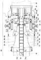
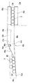
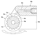
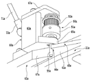
図1は、本発明の実施例に係る小物物品の検査装置100における整列搬送装置1の概略平面図である。図2は、図1に示される整列搬送装置の第2ゲート部を上から見た要部拡大概略図である。図3は、図1に示される整列搬送装置1の振り分け機構を斜め上から見た斜視図である。図4は、図3に示される振り分け機構の要部断面図である。図5は、図3に示す振り分け機構が取り付けられた整列搬送装置を、理解を容易にするために搬送ベルトを取り除いた状態で、斜め下から見た要部斜視図である。図6は、本発明の小物物品の検査装置100における整列搬送装置の一部を示した部分拡大概略図である。以下では、小物物品として錠剤を例に本発明の説明を行う。   FIG. 1 is a schematic plan view of an aligning and conveying apparatus 1 in a small article inspection apparatus 100 according to an embodiment of the present invention. FIG. 2 is an enlarged schematic view of the main part of the second gate portion of the alignment transport device shown in FIG. 1 as viewed from above. FIG. 3 is a perspective view of the sorting mechanism of the alignment transport device 1 shown in FIG. FIG. 4 is a cross-sectional view of the main part of the sorting mechanism shown in FIG. FIG. 5 is a perspective view of an essential part of the alignment transport apparatus to which the sorting mechanism shown in FIG. 3 is attached, as viewed obliquely from below with the transport belt removed for easy understanding. FIG. 6 is a partially enlarged schematic view showing a part of the aligning and conveying apparatus in the small article inspection apparatus 100 of the present invention. Hereinafter, the present invention will be described by taking tablets as examples of small articles.

検査装置100は、主に搬送装置86、整列搬送装置1、検査処理装置85を備えており、搬送装置86で搬送されてきた錠剤Tは、整列搬送装置1で所望の状態に整列されて、検査処理装置85に受け渡される。錠剤Tを整列状態で受け渡された検査処理装置85は、カメラによって錠剤Tの欠けや異物混入の有無の検査を行う。また検査処理装置85では搬送における錠剤Tの詰まりを検知することができる。   The inspection apparatus 100 mainly includes a conveyance device 86, an alignment conveyance device 1, and an inspection processing device 85, and the tablets T conveyed by the conveyance device 86 are aligned in a desired state by the alignment conveyance device 1. It is delivered to the inspection processing device 85. The inspection processing device 85 that has received the tablets T in an aligned state inspects the presence or absence of missing tablets or foreign matter with a camera. Further, the inspection processing device 85 can detect clogging of the tablet T during conveyance.

錠剤Tを搬送する整列搬送装置1は、概略、第1の整列用搬送路10a、第2の搬送路10b、該2つの搬送路10a、10bの間に配置される還元用搬送路80とから構成される。2つの搬送路10a、10bは、略水平に設置され、中心に配置される傾斜した還元用搬送路80を挟んで対称形をなしている。第1の整列用搬送路10aは、錠剤Tを主搬送方向(矢印X方向)に搬送する搬送ベルト11a、錠剤Tを案内するガイド側面21aが形成されているガイド部材20a、第1のゲート部30a及び第2のゲート部40aを含んでいる。搬送ベルト11aは、無端ベルトのコンベアであり、錠剤Tの搬送面が前段の搬送装置86から後段の錠剤検査処理装置85にまで延在するように2つのプーリー間に渡され駆動される。   The aligning and conveying apparatus 1 for conveying the tablets T is roughly composed of a first aligning conveying path 10a, a second conveying path 10b, and a reducing conveying path 80 disposed between the two conveying paths 10a and 10b. Composed. The two transport paths 10a and 10b are installed substantially horizontally and have a symmetrical shape with an inclined return transport path 80 disposed at the center. The first alignment transport path 10a includes a transport belt 11a for transporting the tablet T in the main transport direction (arrow X direction), a guide member 20a on which a guide side surface 21a for guiding the tablet T is formed, and a first gate portion. 30a and a second gate portion 40a. The conveyor belt 11a is an endless belt conveyor, and is passed and driven between two pulleys so that the conveyance surface of the tablet T extends from the preceding conveyance device 86 to the subsequent tablet inspection processing device 85.

ガイド部材20aは、搬送ベルト11aの直上に配置され、上述したように錠剤Tを案内するガイド側面21aを有する。このガイド側面21aは、錠剤Tの主搬送方向上流側の錠剤受け入れ部では、第1の整列用搬送路10aを搬送ベルト11aの幅に略等しく画定しているが、下流に向かって搬送ベルト11aを斜めに遮って横断するように形成されている。すなわち、ガイド部材20aのガイド側面21aは、下流に行くにしたがい錠剤Tを還元用搬送路80側に寄せ、結果として、漸次錠剤Tの第1の整列用搬送路10aの幅を漸次狭めるように、該第1の整列用搬送路10aを画定している。この場合、搬送ベルト11aを斜めに遮って横断するように形成されているガイド側面21aは、直線的であってもよいし、曲線的であってもよい。ガイド側面21aは、さらに、図2に詳細に示されるように、後述する第2ゲート部材40aの入口近傍において第1の整列用搬送路10aの幅が最も狭くなり、搬送される錠剤Tの直径に略等しい幅にまでなるように第1の整列用搬送路10aを画定する。ガイド側面21aは、最終的には主搬送方向(矢印X方向)に平行になるように形成され、後述する第2ゲート部材40aの幅規制ガイド42aとともに、搬送される錠剤T1個分の幅、すなわち搬送される錠剤Tの直径に略等しい幅、となるように第1の整列用搬送路10aを画定する。したがって、ガイド側面21aは、搬送ベルト11aを斜めに遮って横断する傾斜面から搬送ベルト11aの主搬送方向(矢印X方向)に平行となる平行面に向きを変更する構成をとる。   The guide member 20a is disposed immediately above the conveyor belt 11a and has the guide side surface 21a for guiding the tablet T as described above. The guide side surface 21a defines the first alignment transport path 10a substantially equal to the width of the transport belt 11a in the tablet receiving portion on the upstream side in the main transport direction of the tablet T, but the transport belt 11a toward the downstream. It is formed so as to cross diagonally. That is, the guide side surface 21a of the guide member 20a moves the tablet T toward the reducing conveyance path 80 as it goes downstream, and as a result, gradually reduces the width of the first alignment conveyance path 10a of the tablets T. The first alignment transport path 10a is defined. In this case, the guide side surface 21a formed so as to cross the conveyor belt 11a obliquely may be linear or curvilinear. Further, as shown in detail in FIG. 2, the guide side surface 21a has the smallest width of the first alignment transport path 10a in the vicinity of the entrance of the second gate member 40a described later, and the diameter of the tablet T to be transported. The first alignment transport path 10a is defined so as to have a width substantially equal to. The guide side surface 21a is finally formed so as to be parallel to the main transport direction (arrow X direction) and, together with the width regulation guide 42a of the second gate member 40a to be described later, the width of one tablet T to be transported, That is, the first alignment transport path 10a is defined so as to have a width substantially equal to the diameter of the tablet T to be transported. Accordingly, the guide side surface 21a is configured to change the direction from an inclined surface that obliquely blocks and crosses the transport belt 11a to a parallel surface that is parallel to the main transport direction (arrow X direction) of the transport belt 11a.

なお、ガイド部材20aは、本実施例に示されるように、水平方向であって、且つ主搬送方向(矢印X方向)に対して直交する方向に移動可能に構成し、位置調整ツマミ16aにより、ガイド部材20aを、したがってガイド側面21aを移動させ、搬送される錠剤Tの大きさに対応して第1の整列用搬送路10aの幅を調整できるように構成されることが好ましい。なお、符号17aは、ガイド部材20aを基台に固定するためのクランパを示している。   As shown in this embodiment, the guide member 20a is configured to be movable in the horizontal direction and in a direction perpendicular to the main transport direction (arrow X direction), and the position adjustment knob 16a It is preferable that the guide member 20a and therefore the guide side surface 21a are moved so that the width of the first alignment transport path 10a can be adjusted in accordance with the size of the transported tablet T. Reference numeral 17a denotes a clamper for fixing the guide member 20a to the base.

第1ゲート部30aは、第1の整列用搬送路10aの略中間に、該第1の整列用搬送路10aを構成するガイド側面21aに沿って設けられている。第1ゲート部30aは、搬送されてくる錠剤Tに対応して高さを規制する第1の高さ規制ゲート31aから構成される。この第1の高さ規制ゲート31aは、その底面が第1の整列用搬送路10aの搬送面より所定の距離、例えば、錠剤Tの高さより若干長い距離だけ離れ、該搬送面に対して平行になるように、ガイド部材20aに取り付けられている。また、第1の高さ規制ゲート31aには、第1の整列用搬送路10aを斜めに横切り還元用搬送路80にまで延在する側面32aが、高さ規制ゲート31aの底面に対して垂直に形成されている。第1の高さ規制ゲート31aを備える第1ゲート部材30aが第1の整列用搬送路10aの略中間に設けられていることにより、搬送されてくる錠剤Tのうち、立っていたり、重なっていたりする錠剤Tは、ゲート31aの側面32aにより横に倒されたり、重なりを解かれたり、言い換えれば、姿勢を安定した状態にさせられる。あるいは、該側面32aに沿って第1の整列用搬送路10aから還元用搬送路80に向けて排除される。なお、第1の高さ規制ゲート31aは、高さ調整用ツマミ35aにより、その高さ(第1の整列用搬送路10aの搬送面からの距離)を調整できるようにされていることが好ましい。   The first gate portion 30a is provided substantially in the middle of the first alignment transport path 10a along the guide side surface 21a constituting the first alignment transport path 10a. The 1st gate part 30a is comprised from the 1st height control gate 31a which controls height corresponding to the tablet T conveyed. The bottom surface of the first height regulating gate 31a is separated from the transport surface of the first alignment transport path 10a by a predetermined distance, for example, a distance slightly longer than the height of the tablet T, and is parallel to the transport surface. It is attached to the guide member 20a so that it becomes. Further, the first height regulating gate 31a has a side surface 32a that obliquely crosses the first alignment conveying path 10a and extends to the reducing conveying path 80, and is perpendicular to the bottom surface of the height regulating gate 31a. Is formed. The first gate member 30a provided with the first height regulating gate 31a is provided substantially in the middle of the first alignment transport path 10a, so that the tablets T that are transported stand or overlap. The tablet T to be laid down is laid sideways by the side surface 32a of the gate 31a, the overlap is released, in other words, the posture is made stable. Alternatively, it is excluded from the first alignment transport path 10a toward the return transport path 80 along the side surface 32a. The first height regulating gate 31a is preferably configured so that its height (distance from the conveying surface of the first alignment conveying path 10a) can be adjusted by the height adjusting knob 35a. .

第2ゲート部40aは、第1の整列用搬送路10aの下流に、傾斜面から平行面に向きを変更するガイド側面21aに沿って設けられる。第2ゲート部40aは、図2に示されるように、第2の高さ規制ゲート41a、幅規制ガイド42a、振り分け機構、第1サイドガイド43a及び第2サイドガイド44aから構成されている。本実施例では、幅規制ガイド42aは可動することが可能であり、必要に応じて搬送路の幅を広げることができる。この幅規制ガイド42aの動きの詳細については後述する。   The second gate portion 40a is provided downstream of the first alignment transport path 10a along the guide side surface 21a that changes the direction from the inclined surface to the parallel surface. As shown in FIG. 2, the second gate portion 40a includes a second height regulating gate 41a, a width regulating guide 42a, a sorting mechanism, a first side guide 43a, and a second side guide 44a. In the present embodiment, the width regulation guide 42a can move, and the width of the conveyance path can be increased as necessary. Details of the movement of the width regulation guide 42a will be described later.

第2の高さ規制ゲート41aの外側(還元用搬送路80側)は、その上流側で、第1の整列用搬送路10aを斜めに横切り還元用搬送路80にまで延在し、第2の高さ規制ゲート41aの底面に対して垂直な側面45a、及び後述する振り分け機構を構成する回転軸55a先端が第2の高さ規制ゲート41aの下方に突出し、第1の整列用搬送路10a上に臨むことを可能とする溝46aを備えている。該溝46aの深さは、振り分け機構を構成する回転軸55aが第1の整列用搬送路10aの還元用搬送路80側縁部、すなわち搬送ベルト11aの還元用搬送路80側縁部、の近傍に配置できるように設定される。なお、溝46aは、第2の高さ規制ゲート41aを上下方向(図2において、紙面に垂直な方向)に貫通する貫通孔であってもよい。   On the upstream side of the second height regulating gate 41a (reduction conveyance path 80 side), the first alignment conveyance path 10a obliquely crosses the first alignment conveyance path 10a and extends to the reduction conveyance path 80. The side surface 45a perpendicular to the bottom surface of the height regulating gate 41a and the tip of the rotating shaft 55a constituting the sorting mechanism to be described later protrude below the second height regulating gate 41a, and the first alignment transport path 10a. It has a groove 46a that allows it to face upward. The depth of the groove 46a is such that the rotating shaft 55a constituting the sorting mechanism is located at the edge of the first alignment transport path 10a on the side of the transport path 80 for reduction, that is, the edge of the transport belt 11a on the side of the transport path 80 for reduction. It is set so that it can be placed in the vicinity. The groove 46a may be a through hole penetrating the second height regulating gate 41a in the vertical direction (the direction perpendicular to the paper surface in FIG. 2).

第2の高さ規制ゲート41aの内側は、ガイド部材20aのガイド側面21aに沿うように、また、上記第1の高さ規制ゲート31aと同様に、その底面が第1の整列用搬送路10aの搬送面より所定の距離、例えば、錠剤Tの高さより若干長い距離だけ離れ、該搬送面10aに対して平行になるように、ガイド部材20aに取り付けられる。第2の高さ規制ゲート41aの底面に対して垂直な側面45aは、依然として不安定な姿勢にある錠剤Tを、還元用搬送路80に排除する。本実施例において、幅規制ガイド42aは、第2の高さ規制ゲート41aの溝46aから下流側に延在している。この構成から、振り分け機構を構成する回転軸55aは、幅規制ガイド42aの上流側端部の近くに配置されることが理解される。幅規制ガイド42aは、また、その内側側面がガイド部材20aのガイド側面21aに対して所定の距離、例えば、錠剤Tの直径より若干長い距離だけ離れ、該ガイド側面21aに対して平行になるように配置される。結果として、幅規制ガイド42aの内側側面48aとガイド部材20aのガイド側面21aとで錠剤Tの直径分の幅を有する第1の整列用搬送路10a、すなわち、錠剤Tを一列に整列させて搬送させる搬送路10aが形成される。さらに、幅規制ガイド42aの外側(還元用搬送路80側)は、図2、5に示されるように、上流側が先細りになるように傾斜側面47aが形成されていることが好ましい。傾斜側面47aを備えることにより、後述する振り分け機構(より詳細には、回転軸55a)で還元用搬送路80側に振り分けられた錠剤Tが円滑に還元用搬送路80に落下することができる。しかしながら、幅規制ガイド42aは、傾斜側面47aを備えていなくてもよい。例えば、幅規制ガイド42aの外側形状は、第2の高さゲート41aの外側形状と同じであってもよい。なお、第2の高さ規制ゲート41aは、高さを調整できるように構成されていることが好ましい。   The inner side of the second height regulating gate 41a is along the guide side surface 21a of the guide member 20a, and the bottom surface of the second height regulating gate 41a is the same as the first height regulating gate 31a. It is attached to the guide member 20a so as to be separated from the transport surface by a predetermined distance, for example, a distance slightly longer than the height of the tablet T and to be parallel to the transport surface 10a. The side surface 45a perpendicular to the bottom surface of the second height regulating gate 41a excludes the tablet T that is still in an unstable posture into the reducing conveyance path 80. In the present embodiment, the width regulation guide 42a extends downstream from the groove 46a of the second height regulation gate 41a. From this configuration, it is understood that the rotation shaft 55a constituting the distribution mechanism is disposed near the upstream end portion of the width regulating guide 42a. The width regulating guide 42a also has an inner side surface that is separated from the guide side surface 21a of the guide member 20a by a predetermined distance, for example, a distance slightly longer than the diameter of the tablet T, and parallel to the guide side surface 21a. Placed in. As a result, the first alignment transport path 10a having a width corresponding to the diameter of the tablet T on the inner side surface 48a of the width regulating guide 42a and the guide side surface 21a of the guide member 20a, that is, the tablets T are transported in a line. A conveyance path 10a is formed. Furthermore, as shown in FIGS. 2 and 5, it is preferable that an inclined side surface 47 a is formed on the outer side of the width regulation guide 42 a (return conveyance path 80 side) so that the upstream side is tapered. By providing the inclined side surface 47a, the tablets T distributed to the reduction conveyance path 80 side by the distribution mechanism (more specifically, the rotation shaft 55a) described later can smoothly fall into the reduction conveyance path 80. However, the width regulating guide 42a may not include the inclined side surface 47a. For example, the outer shape of the width regulating guide 42a may be the same as the outer shape of the second height gate 41a. In addition, it is preferable that the 2nd height control gate 41a is comprised so that height can be adjusted.

図3ないし図5に該振り分け機構の詳細図が示されている。図3、5に示されるように、該振り分け機構は、概略、風車50a及び風力ブロック60aを備えている。風車50aは、風車本体51a、凹凸車52a、回転軸55a、第1軸受部56a及び第2軸受部57aを備えている。風車本体51aは、凹凸車52aを支持する部材であり、中心部に貫通孔が形成されている円筒状をなしている。風車本体51aの中心貫通孔を回転軸55aが貫通し、風車本体51aに形成されている軸固定用孔54aを介してネジ等により風車本体51aと回転軸55aが一体化される。凹凸車52aは、風車本体51a上に配置され、適宜の手段で風車本体51aに固定される。凹凸車52aは、外周に複数の凸部53a(図4参照)が形成され、中心部に回転軸55aが貫通する貫通孔が形成されている。凹凸車52aの外周に形成される凸部53aは、歯車の歯の形状をしていてもよいし、平板状の羽根のような形状であってもよい。要は、圧縮空気の吹き付けを受け止めることができる形状であればどのような形状であってもよい。回転軸55aは、錠剤Tを振り分ける部材であり、風車本体51a、凹凸車52aそれぞれの貫通孔を貫通し、風車本体51a及び凹凸車52aを挟んで両側に配置されている第1軸受部56a及び第2軸受部57aにより回転可能に支持される。   3 to 5 are detailed views of the distribution mechanism. As shown in FIGS. 3 and 5, the distribution mechanism roughly includes a windmill 50a and a wind block 60a. The windmill 50a includes a windmill main body 51a, an uneven wheel 52a, a rotating shaft 55a, a first bearing portion 56a, and a second bearing portion 57a. The windmill main body 51a is a member that supports the uneven wheel 52a, and has a cylindrical shape with a through hole formed in the center. The rotation shaft 55a passes through the center through hole of the windmill main body 51a, and the windmill main body 51a and the rotation shaft 55a are integrated by a screw or the like through a shaft fixing hole 54a formed in the windmill main body 51a. The uneven wheel 52a is disposed on the windmill main body 51a and is fixed to the windmill main body 51a by an appropriate means. In the uneven wheel 52a, a plurality of convex portions 53a (see FIG. 4) are formed on the outer periphery, and a through hole through which the rotation shaft 55a passes is formed in the center portion. The convex part 53a formed in the outer periphery of the uneven | corrugated wheel 52a may have the shape of the tooth | gear of a gearwheel, and may be a shape like a flat blade | wing. In short, any shape can be used as long as it can catch the blowing of compressed air. The rotation shaft 55a is a member that distributes the tablets T, passes through the through holes of the windmill body 51a and the uneven wheel 52a, and has first bearing portions 56a disposed on both sides of the windmill body 51a and the uneven wheel 52a. The second bearing portion 57a is rotatably supported.

また、回転軸55aは、図に示されるように、下方端部を第2軸受部57aから所定の長さ突出させ、該突出部分の自由端を、錠剤Tを振り分ける部材として機能させる。回転軸55aは、どのような材料を用いて作られてもよいが、表面がテフロン(登録商標)処理されたステンレス鋼(SUS)で作られるのが好ましい。さらに、回転軸55aの直径は、錠剤Tが扁平な円形状の錠剤(丸錠)である場合、その径より若干小さい(約1mm小さい)径であることが好ましい。例えば、錠剤Tの径が5mmであるとすると、回転軸55aの径は4mmであることが好ましい。あるいは、錠剤が楕円やオーバル形状のような断面長円形状の錠剤(異形錠)である場合、回転軸55aの直径は、短軸のほうの長さより若干小さいことが好ましい。回転軸55aの径は、大きすぎると、錠剤が詰まりやすく、小さすぎると、回転軸55aの強度が弱くなり、該軸55aが曲がってしまう恐れがある。風力ブロック60aは、風車50aを回転可能に支持するとともに、図4に示されるように、風車50aの凹凸車52aに圧縮空気を吹き付ける機能を備える。圧縮空気を吹き付けることにより、一体化されている風車本体51a、凹凸車52a及び回転軸55aを反時計方向、すなわち、錠剤を整列用搬送路に取り込む方向、に回転させる。風力ブロック60aは、ブロック本体61a、及び第1の軸受保持体67aを備えている。   Further, as shown in the drawing, the rotating shaft 55a projects a lower end portion from the second bearing portion 57a by a predetermined length, and allows the free end of the projecting portion to function as a member for distributing the tablets T. The rotating shaft 55a may be made of any material, but is preferably made of stainless steel (SUS) having a surface treated with Teflon (registered trademark). Furthermore, when the tablet T is a flat circular tablet (round tablet), the diameter of the rotation shaft 55a is preferably slightly smaller (about 1 mm smaller) than the diameter. For example, when the diameter of the tablet T is 5 mm, the diameter of the rotating shaft 55a is preferably 4 mm. Alternatively, in the case where the tablet is an oval or oval cross-sectional tablet (an irregular tablet), the diameter of the rotation shaft 55a is preferably slightly smaller than the length of the short axis. If the diameter of the rotation shaft 55a is too large, the tablet is likely to be clogged, and if it is too small, the strength of the rotation shaft 55a becomes weak and the shaft 55a may be bent. The wind power block 60a rotatably supports the windmill 50a and has a function of blowing compressed air to the uneven wheel 52a of the windmill 50a as shown in FIG. By blowing the compressed air, the integrated windmill main body 51a, concave / convex wheel 52a and rotating shaft 55a are rotated in the counterclockwise direction, that is, the direction in which the tablets are taken into the conveying path for alignment. The wind power block 60a includes a block main body 61a and a first bearing holder 67a.

ブロック本体61aは、縦ブロック62a、ベース65aを有し、該縦ブロック62aとベース65aとで略L字形をなしている。縦ブロック62aには、空気供給管71aから管継手72a及び通路63aを介して送られてくる圧縮空気を風車50aの凹凸車52aに吹き付ける吹き付け孔64aが設けられている。ベース65aは、第2の軸受保持体を構成するとともに、固定孔66aが形成されている。ブロック本体61aは、固定孔66aを介してネジ等で第2ゲート部40aの第2高さ規制ゲート41a上に着脱自在に取り付けられる(図5参照)。第1の軸受け保持体67aは、ネジ部材68a等で縦ブロック62a上に固定される。また、第1の軸受保持体67a及びベース65aは、それぞれに形成されている取り付け孔に上記風車50aの第1軸受部56a及び第2軸受部57aをそれぞれ圧入する等の固定方法を採用して、該風車50aを回動可能に支持する。   The block main body 61a has a vertical block 62a and a base 65a, and the vertical block 62a and the base 65a are substantially L-shaped. The vertical block 62a is provided with a blowing hole 64a for blowing compressed air sent from the air supply pipe 71a through the pipe joint 72a and the passage 63a to the uneven wheel 52a of the windmill 50a. The base 65a constitutes a second bearing holder, and a fixing hole 66a is formed. The block main body 61a is detachably attached to the second height regulating gate 41a of the second gate portion 40a with a screw or the like through the fixing hole 66a (see FIG. 5). The first bearing holder 67a is fixed on the vertical block 62a with a screw member 68a or the like. Further, the first bearing holder 67a and the base 65a employ a fixing method such as press-fitting the first bearing portion 56a and the second bearing portion 57a of the windmill 50a into the mounting holes formed respectively. The windmill 50a is rotatably supported.

図5に示されるように、振り分け機構を構成する風車50a及び風力ブロック60aが第2の高さ規制ゲート45a上に組み立てられると、風車50aの回転軸55aの下方先端部は、第2高さ規制ゲート41aの溝46aを通り抜け、第1の整列用搬送路10aに臨むことになる。この場合、風車50aの回転軸55aの下方自由端は、第1の整列用搬送路10aを構成する搬送ベルト11aの上面に対して搬送される錠剤Tの高さ(厚さ)より小さいが、搬送ベルト11の上面に触れない距離だけ離れて配置されることが理解されるであろう。また、回転軸55aは、幅規制ガイド42aの上流側端部近傍であって、ガイド側面21aが傾斜面から平行面に向きを変更する箇所に第1の整列用搬送路10aを挟んで対向する、搬送ベルト11aの還元用搬送路80側縁部近傍に配置される。なお、図示されていないが、振り分け機構は、整列搬送装置1として組み立てられたとき、全体がカバー等で覆われていることがより好ましい。   As shown in FIG. 5, when the wind turbine 50a and the wind turbine block 60a constituting the distribution mechanism are assembled on the second height regulating gate 45a, the lower end portion of the rotating shaft 55a of the wind turbine 50a has the second height. It passes through the groove 46a of the regulating gate 41a and faces the first alignment transport path 10a. In this case, the lower free end of the rotation shaft 55a of the windmill 50a is smaller than the height (thickness) of the tablet T conveyed relative to the upper surface of the conveyance belt 11a constituting the first alignment conveyance path 10a. It will be understood that they are arranged at a distance that does not touch the top surface of the conveyor belt 11. Further, the rotation shaft 55a is in the vicinity of the upstream end portion of the width regulating guide 42a, and is opposed to the portion where the direction of the guide side surface 21a is changed from the inclined surface to the parallel surface with the first alignment transport path 10a interposed therebetween. The conveyor belt 11a is disposed in the vicinity of the edge on the side of the conveyance path 80 for reduction. Although not shown, it is more preferable that the sorting mechanism is entirely covered with a cover or the like when assembled as the alignment transport device 1.

本実施例における振り分け機構は、上述のような構成を備えることで、吹き付け孔64aから吐出される圧縮空気が、図4に示されるように、凹凸車52aの凸部53aに当たることで凹凸車52aが図において反時計方向に回転する。それにより、該凹凸車52aと一体に形成されている風車本体51aも回転する。結果として、風車本体51aと一体化されている回転軸55aが、反時計方向、すなわち、錠剤を第1の整列用搬送路10aに取り込む方向に回転し、回転軸55aにぶつかってくる錠剤Tを円滑に第1の整列用搬送路10aに導き、錠剤Tの停滞を阻止することができる。仮に、錠剤Tが、回転軸55aとガイド部材20aのガイド側面21aとの間に挟み込まれて停滞しようとしても、従来例にも存在する後続する錠剤の押し込み作用に加えて、回転軸55aの回転力による取り込み作用が働くことより錠剤Tはほとんど停滞することがない。また、回転軸55aの回転は、圧縮空気の吹き付け力によるものであるから、瞬間的に停滞が起こって回転軸55aに負荷がかかったとしても、回転軸55aの回転が容易に減速または停止する。それにより、本実施例における振り分け機構は、モーター等で回転軸55を強制的に駆動することに比べて錠剤Tに無理な力がかからず、錠剤Tを破損させることもない。   The distribution mechanism in the present embodiment has the above-described configuration, so that the compressed air discharged from the blowing hole 64a hits the convex portion 53a of the concave / convex vehicle 52a as shown in FIG. Rotates counterclockwise in the figure. Thereby, the windmill main body 51a formed integrally with the uneven wheel 52a also rotates. As a result, the rotating shaft 55a integrated with the windmill main body 51a rotates counterclockwise, that is, in the direction in which the tablets are taken into the first alignment transport path 10a, and the tablet T hitting the rotating shaft 55a is removed. It is possible to smoothly guide to the first alignment transport path 10a and prevent the stagnation of the tablet T. Even if the tablet T is sandwiched between the rotation shaft 55a and the guide side surface 21a of the guide member 20a and tries to stagnate, the rotation of the rotation shaft 55a is added to the subsequent tablet pushing action that also exists in the conventional example. The tablet T hardly stagnates due to the action of taking in force. Further, since the rotation of the rotating shaft 55a is due to the blowing force of the compressed air, even if the stagnation occurs momentarily and a load is applied to the rotating shaft 55a, the rotation of the rotating shaft 55a is easily decelerated or stopped. . Thereby, the sorting mechanism in the present embodiment does not apply excessive force to the tablet T and does not damage the tablet T as compared to forcibly driving the rotating shaft 55 with a motor or the like.

なお、回転軸55aの回転速度の制御は、圧縮空気の圧力や流量を調整することにより、凹凸車52aに吹き付けられる空気の速度を変えることで容易に行なうことができる。また、圧縮空気供給源としては、搬送ベルトの清掃や検査用カメラの防塵用等の装置に供
給される工場施設内に備えられているコンプレッサ等を使用する。
In addition, control of the rotational speed of the rotating shaft 55a can be easily performed by changing the speed of the air sprayed on the uneven wheel 52a by adjusting the pressure and flow rate of the compressed air. In addition, as a compressed air supply source, a compressor or the like provided in a factory facility supplied to an apparatus for cleaning the conveyor belt or dustproof for an inspection camera is used.

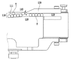
図6は、本発明の特徴的な構成である幅規制ガイド42aの開閉動作を説明するための図である。幅規制ガイド42aと第1サイドガイド43aとは一体で構成されている部材であるため、開閉動作の際は一体となって移動する。幅規制ガイド42aは不図示のリニアスライドを介して支持部材80aに取り付けられている。また、幅規制ガイド42aの一端部は、エアシリンダ82aと接続されている。また、エアシリンダ82aはブラケット81aを介して支持部材80aに取り付けられており、その取り付け位置は、長穴によって調整が可能となっている。幅規制ガイド42aは、エアシリンダ82aを駆動させることで、矢印α方向への移動によって整列用搬送路10aの開閉動作を行うことができる。なお、本明細書では、幅規制ガイド42aの移動動作に「開閉動作」という言葉を用いているが、後述する説明からも明らかなように、「閉」の状態で実際に幅規制ガイド42aが整列用搬送路10aを閉じて遮断しているものではなく、整列用搬送路10aの幅を狭くしている状態を「閉」の状態と言うものとする。   FIG. 6 is a view for explaining the opening / closing operation of the width regulating guide 42a, which is a characteristic configuration of the present invention. Since the width regulation guide 42a and the first side guide 43a are members formed integrally, they move together during the opening / closing operation. The width regulating guide 42a is attached to the support member 80a via a linear slide (not shown). One end of the width regulation guide 42a is connected to the air cylinder 82a. The air cylinder 82a is attached to the support member 80a via a bracket 81a, and the attachment position can be adjusted by a long hole. The width regulating guide 42a can open and close the alignment transport path 10a by moving in the direction of the arrow α by driving the air cylinder 82a. In the present specification, the term “opening / closing operation” is used for the movement operation of the width regulating guide 42a. However, as will be apparent from the following description, the width regulating guide 42a is actually in the “closed” state. The state in which the width of the alignment transport path 10a is narrowed is referred to as a “closed” state, rather than the alignment transport path 10a being closed and blocked.

第1サイドガイド43a、第2サイドガイド44aは、幅規制ガイド42aの内側側面48aとガイド部材20aのガイド側面21aとで画成される搬送路から送られてくる錠剤Tを後工程の錠剤検査処理装置85へ受け渡すための構成要素である。したがって通常運転が行われている場合は、第1サイドガイド43aと第2サイドガイド44aとは、錠剤Tの直径より若干長い距離だけ離れ、かつ互いに対して平行になるように配置されて、幅規制ガイド42aの開閉動作における「閉」の状態(図6の実線で示した位置)で錠剤の搬送が行われる。この時、第1サイドガイド43aと第2サイドガイド44aとの幅は、不図示のマイクロメータヘッドによってその間の距離を調整可能に構成されている。従って、搬送する錠剤Tの寸法に合わせて適宜幅を変更することが可能である。この第1サイドガイド43aと第2サイドガイド44aとで画成される搬送路は、錠剤Tの主搬送方向(矢印X方向)にも平行に形成される。   The first side guide 43a and the second side guide 44a are used to inspect the tablets T sent from the conveyance path defined by the inner side surface 48a of the width regulating guide 42a and the guide side surface 21a of the guide member 20a in the subsequent process. It is a component for delivery to the processing device 85. Therefore, when the normal operation is performed, the first side guide 43a and the second side guide 44a are arranged so as to be separated from each other by a distance slightly longer than the diameter of the tablet T and parallel to each other. The tablets are transported in the “closed” state (position indicated by the solid line in FIG. 6) in the opening / closing operation of the regulation guide 42a. At this time, the width of the first side guide 43a and the second side guide 44a is configured such that the distance between them can be adjusted by a micrometer head (not shown). Therefore, the width can be appropriately changed according to the size of the tablet T to be conveyed. The conveyance path defined by the first side guide 43a and the second side guide 44a is formed in parallel to the main conveyance direction (arrow X direction) of the tablet T.

また、錠剤Tが幅規制ガイド42aにガイドされてから一列に整列するまでの間のいずれかで詰まりが生じて、錠剤検査処理装置85で詰まりが検知されたた場合には、エアシリンダ82aを駆動させて、幅規制ガイド42aを開閉動作における「開」の位置(図6の二点鎖線で示した位置)まで移動させて、第1の整列用搬送路10aの幅を拡張させる。幅規制ガイド42aの移動量は、錠剤の形状、寸法によって適宜変更することが好ましい。なお本実施例では、第1の整列用搬送路10aの幅を4mm拡張させるように幅規制ガイド42aを移動させるが、基本的には、搬送ベルト11aの側端部から錠剤が落下しなければよい。幅規制ガイド42aが「開」の位置まで移動すると、錠剤除去エアノズル83aから搬送路の上流側に向けて空気が吹き出される。搬送路を搬送されてくる錠剤Tは、錠剤除去エアノズル83aから吹き出された空気によって、搬送を妨げられ、錠剤除去エアノズル83aよりも下流には進入することができなくなる。その間に、既に錠剤除去エアノズル83aを通過して、整列した錠剤Tおよび詰まりを生じさせた錠剤Tは、幅を拡張させた整列用搬送路10aを通過する。   If clogging occurs between the time when the tablet T is guided by the width regulation guide 42a and the time when the tablet T is aligned in a line, and the clogging is detected by the tablet inspection processing device 85, the air cylinder 82a is turned on. By driving, the width regulating guide 42a is moved to the “open” position (position indicated by the two-dot chain line in FIG. 6) in the opening / closing operation, and the width of the first alignment transport path 10a is expanded. The amount of movement of the width regulation guide 42a is preferably changed as appropriate according to the shape and dimensions of the tablet. In this embodiment, the width regulating guide 42a is moved so as to expand the width of the first alignment transport path 10a by 4 mm. Basically, if the tablet does not fall from the side end of the transport belt 11a. Good. When the width regulation guide 42a moves to the “open” position, air is blown out from the tablet removal air nozzle 83a toward the upstream side of the conveyance path. The tablets T transported through the transport path are prevented from being transported by the air blown out from the tablet removal air nozzle 83a, and cannot enter downstream of the tablet removal air nozzle 83a. In the meantime, the aligned tablets T and the tablets T that have been clogged, which have already passed through the tablet removal air nozzle 83a, pass through the alignment conveying path 10a whose width is expanded.

この整列搬送装置1は、錠剤Tの搬送下流側において、この後工程で用いられる検査処理装置85と接続されている。通常運転、つまり錠剤の詰まりが生じていない場合には、一列に整列された錠剤Tが検査処理装置85に受け渡される。しかし、錠剤Tの詰まり除去動作が行われると、検査処理装置85は上昇して、整列搬送装置1と検査処理装置85との接続を解除し、検査処理装置85への錠剤Tの受け渡しが行われないようにする。したがって、詰まりが生じた際に、既に錠剤除去エアノズル83aを通過した、整列している錠剤Tおよび詰まりを生じさせた錠剤Tは全て、整列搬送装置1に搬送方向後端部に設けられた錠剤回収箱84に落下して回収される。   The aligning / conveying device 1 is connected to an inspection processing device 85 used in a subsequent process on the downstream side of the tablet T conveyance. In the normal operation, that is, when the tablets are not clogged, the tablets T arranged in a line are delivered to the inspection processing device 85. However, when the clogging removal operation of the tablet T is performed, the inspection processing device 85 is lifted, the connection between the alignment transport device 1 and the inspection processing device 85 is released, and the tablet T is delivered to the inspection processing device 85. Don't break. Therefore, when the clogging occurs, all of the aligned tablets T and the clogged tablets T that have already passed through the tablet removal air nozzle 83a are provided to the alignment conveyance device 1 at the rear end in the conveyance direction. It drops into the collection box 84 and is collected.

このように錠剤Tが回収され、錠剤の詰まりが除去されると、改めてエアシリンダ82aを駆動させて、幅規制ガイド42aを「閉」の位置まで移動する。そして、検査処理装置85を下降させて整列搬送装置1と再接続させ、錠剤除去エアノズル83aからの空気の吹き出しを止める。このように、幅規制ガイド42aでガイドされる箇所における錠剤Tの詰まりが解消された状態で、再び通常運転が開始される。   When the tablet T is collected in this way and the clogging of the tablet is removed, the air cylinder 82a is driven again to move the width regulation guide 42a to the “closed” position. Then, the inspection processing device 85 is lowered and reconnected to the alignment transport device 1, and the blowing of air from the tablet removal air nozzle 83a is stopped. In this way, the normal operation is started again in a state where the clogging of the tablet T at the portion guided by the width regulation guide 42a is eliminated.

なお、振り分け機構は本体側に固定されているため、錠剤Tの詰まり発生時に幅規制ガイド42aが移動しても振り分け機構自体が移動することは無い。   Since the sorting mechanism is fixed to the main body, the sorting mechanism itself does not move even if the width regulation guide 42a moves when the tablet T is clogged.

また、図2に示されるように、この第1サイドガイド43aと第2サイドガイド44aとで画成される搬送路は、後工程の錠剤検査処理装置85へ受け渡すべく第2の高さ規制ガイド41aには覆われていない。   In addition, as shown in FIG. 2, the conveyance path defined by the first side guide 43a and the second side guide 44a has a second height restriction for delivery to the tablet inspection processing device 85 in the subsequent process. The guide 41a is not covered.

このように、錠剤Tの詰まりが生じた際に、幅規制ガイド42aを移動させることで第1の整列用搬送路10aの幅を拡張させて、詰まりの原因となった錠剤および搬送の滞った錠剤を錠剤回収箱84に落下させて回収する。そして、回収後に再び通常運転を開始する。このように詰まりを除去することが可能な錠剤詰まり除去機構によって、所定の整列処理能力を向上させることができる。   As described above, when the tablet T is clogged, the width of the first alignment transport path 10a is expanded by moving the width regulation guide 42a, and the tablets that cause clogging and the transport are delayed. The tablets are dropped into the tablet collection box 84 and collected. And normal operation | movement is started again after collection | recovery. A predetermined clogging processing capability can be improved by the tablet clogging removal mechanism capable of removing clogging in this way.

第2の整列用搬送路(図1において、還元用搬送路80を挟んで整列用搬送路10aと対向する位置にある搬送路)10bは、第1の整列用搬送路10aと対をなしており、実質的に同じ構造をしているので説明は省略する(各構成要素は、第1の整列用搬送路の構成要素と同じ数字にアルファベットのaに替えてbを付している)。   A second alignment transport path (a transport path in a position facing the alignment transport path 10a across the reduction transport path 80 in FIG. 1) 10b forms a pair with the first alignment transport path 10a. Since the structure is substantially the same, the description thereof is omitted (each component is given the same numeral as the component of the first alignment transport path by substituting the letter a for b).

還元用搬送路80は、図1に示されるように、対称形状を有する第1の整列用搬送路10aと第2の整列用搬送路10bとの間に配置され、第1、第2の整列用搬送路10a、10bから排除される錠剤Tを、各整列搬送装置10a、10bの上流に配置される搬送装置86に戻し、再度第1の整列用搬送路10a又は第2の整列用搬送路10bを通過させ、整列させるためのものである。還元用搬送路80の具体的構成は、従来例と同様であり、ここでは説明を省略する。   As shown in FIG. 1, the reduction conveyance path 80 is disposed between the first alignment conveyance path 10 a and the second alignment conveyance path 10 b having a symmetrical shape, and the first and second alignment paths are arranged. The tablets T excluded from the transport paths 10a, 10b are returned to the transport apparatus 86 disposed upstream of the alignment transport apparatuses 10a, 10b, and again the first alignment transport path 10a or the second alignment transport path. 10b is passed and aligned. The specific configuration of the return conveyance path 80 is the same as that of the conventional example, and the description thereof is omitted here.

次に、本実施例の整列搬送装置1における錠剤Tの搬送動作を説明する。不図示のホッパなどから定量的に放出される錠剤Tは、搬送装置86で振動を与えられ、搬送装置86下流に設けられるフィンF1a、F1bにより適宜振り分けられ、本実施例の整列搬送装置1の各整列用搬送路10a、10bに送られてくる。この時、フィンF1a、F1bにより、錠剤Tは、各整列用搬送路10a、10bのそれぞれのガイド側面21a、21bに向けられるように案内される。各整列搬送路10a、10bを搬送される錠剤Tは、第1ゲート部30a、30bで安定した姿勢の錠剤のみ通過するように取捨選択され、第2ゲート部40a、40bで、安定した姿勢で且つ一個の錠剤のみが取捨選択され、結果として一列に整列される。第2ゲート部40a、40bの第1サイドガイド43a、43bと第2サイドガイド44a、44bとでそれぞれ画成される各整列搬送路10a、10bに到達した錠剤Tは、整列搬送装置1全体としては2列に整列されて後段の錠剤検査処理装置85に受け渡される。   Next, the conveying operation of the tablet T in the alignment conveying apparatus 1 of a present Example is demonstrated. Tablets T that are quantitatively released from a hopper (not shown) or the like are vibrated by the transport device 86 and are appropriately distributed by the fins F1a and F1b provided downstream of the transport device 86. It is sent to each of the alignment conveying paths 10a and 10b. At this time, the tablets T are guided by the fins F1a and F1b so as to be directed to the guide side surfaces 21a and 21b of the alignment conveying paths 10a and 10b. The tablets T transported through the alignment transport paths 10a and 10b are selected so that only the tablets in a stable posture pass through the first gate portions 30a and 30b, and in a stable posture in the second gate portions 40a and 40b. And only one tablet is selected and consequently aligned in a row. The tablets T that have arrived at the respective alignment transport paths 10a and 10b defined by the first side guides 43a and 43b and the second side guides 44a and 44b of the second gate portions 40a and 40b are arranged as the entire alignment transport apparatus 1. Are arranged in two rows and delivered to the subsequent tablet inspection processor 85.

以上、本発明に係る錠剤の検査装置100に関して説明を行ったが、本発明は、このような錠剤の搬送に限られないことは言うまでもない。特に、本発明は、楕円、オーバル形状等のような断面長円形状の錠剤(異形錠)やRのきつい錠剤等の整列搬送に有効である。また、本実施例の検査装置100における整列搬送装置1では、2つの整列用搬送路と1つの還元用搬送路を備えているが、1つの整列用搬送路と1つの還元用搬送路とを備えたものであってもよいし、その他の組み合わせであってもよい。   The tablet inspection apparatus 100 according to the present invention has been described above. Needless to say, the present invention is not limited to such tablet conveyance. In particular, the present invention is effective for aligning and conveying tablets having an elliptical cross section (an irregular tablet) such as an ellipse and an oval shape, and R-tight tablets. Further, the alignment transport apparatus 1 in the inspection apparatus 100 of the present embodiment includes two alignment transport paths and one return transport path, but includes one alignment transport path and one return transport path. It may be provided, or other combinations may be used.

1 整列搬送装置
10a 第1の整列搬送路
10b 第2の整列搬送路
30a 第1ゲート部
40a 第2ゲート部
42a 幅規制ガイド
43a 第1サイドガイド
44a 第2サイドガイド
80 還元用搬送路
82a エアシリンダ
84 錠剤回収箱
85 錠剤検査処理装置
86 搬送装置
100 検査装置
T 錠剤
DESCRIPTION OF SYMBOLS 1 Alignment conveyance apparatus 10a 1st alignment conveyance path 10b 2nd alignment conveyance path 30a 1st gate part 40a 2nd gate part 42a Width control guide 43a 1st side guide 44a 2nd side guide 80 Reduction conveyance path 82a Air cylinder 84 Tablet collection box 85 Tablet inspection processing device 86 Transport device 100 Inspection device T Tablet

Claims (5)

搬送路にて小物物品を載せて搬送する搬送ベルトと、該搬送ベルト上に配置され、小物物品を案内するガイド側面を有するガイド部材と、前記搬送ベルト上を搬送される小物物品が安定した姿勢で且つ一つのみ通過できるように、前記ガイド部材のガイド側面との間で前記搬送路における整列用搬送路の幅を規制する側面を有する幅規制ガイドと、該幅規制ガイドの上流側端部に配置された、搬送されてきた前記小物物品を振り分けるための回転軸と、前記搬送ベルトの搬送方向終端部に設けられた小物物品回収箱と、を含む詰まり除去機構において
前記幅規制ガイドは、移動することで前記整列用搬送路の幅を拡張することを特徴とする詰まり除去機構。
A conveying belt that carries and conveys small articles on the conveying path, a guide member that is disposed on the conveying belt and has a guide side surface that guides the small articles, and a small article that is conveyed on the conveying belt is in a stable posture. And a width regulating guide having a side surface for regulating the width of the conveying path for alignment in the conveying path between the guide side surface of the guide member and an upstream end of the width regulating guide so that only one can pass therethrough. In the clogging removal mechanism, which includes a rotating shaft for distributing the small articles that have been conveyed, and a small article collection box provided at the end of the conveyance belt in the conveyance direction. A clogging removal mechanism that expands the width of the alignment transport path by moving.
前記幅規制ガイドは、搬送中の前記小物物品に詰まりが生じた際に前記整列用搬送路の幅を拡張することを特徴とする請求項1に記載の詰まり除去機構。   The clogging removal mechanism according to claim 1, wherein the width regulating guide expands a width of the alignment conveying path when clogging occurs in the small article being conveyed. 前記幅規制ガイドの搬送方向における上流側に、小物物品除去エアノズルを備えており、前記幅規制ガイドが移動する際に、前記小物物品除去エアノズルから搬送方向上流側に向けて空気を吹き出すことで、前記小物物品除去エアノズルから下流側への前記小物物品の搬送を妨げることを特徴とする請求項1または請求項2に記載の詰まり除去機構。   A small article removal air nozzle is provided on the upstream side in the conveyance direction of the width regulation guide, and when the width regulation guide moves, by blowing air from the small article removal air nozzle toward the upstream side in the conveyance direction, The clogging removal mechanism according to claim 1 or 2, wherein conveyance of the small article from the small article removal air nozzle to the downstream side is prevented. 前記幅規制ガイドが移動して前記整列用搬送路が拡張されると、前記幅規制ガイドによってガイドされている搬送中の小物物品および前記小物物品除去エアノズルから搬送方向下流側にある小物物品は、前記小物物品回収箱に回収されることを特徴とする請求項3に記載の詰まり除去機構。   When the width regulating guide is moved and the conveying path for alignment is expanded, the small article being conveyed guided by the width regulating guide and the small article on the downstream side in the conveying direction from the small article removing air nozzle are: The clogging mechanism according to claim 3, wherein the clogging mechanism is collected in the small article collection box. 請求項1ないし請求項4のいずれか1項に記載の詰まり除去機構と、
該詰まり除去機構と接続され、前記詰まり除去機構の後工程で、小物物品の検査を行う検査処理機構と、を備え、小物物品の搬送中に詰まりが生じた際に、前記詰まり除去機構と前記検査処理機構との接続を解除し、前記幅規制ガイドが移動することで前記整列用搬送路の幅を拡張することを特徴とする検査装置。
The clogging removal mechanism according to any one of claims 1 to 4,
An inspection processing mechanism that is connected to the clogging removal mechanism and inspects small articles in a subsequent step of the clogging removal mechanism, and when clogging occurs during conveyance of the small articles, the clogging removal mechanism and the An inspection apparatus that releases a connection with an inspection processing mechanism and expands the width of the alignment conveying path by moving the width regulation guide.
JP2010147930A 2010-06-29 2010-06-29 Clogging removal mechanism and inspection device Active JP5551982B2 (en)

Priority Applications (1)

Application Number Priority Date Filing Date Title
JP2010147930A JP5551982B2 (en) 2010-06-29 2010-06-29 Clogging removal mechanism and inspection device

Applications Claiming Priority (1)

Application Number Priority Date Filing Date Title
JP2010147930A JP5551982B2 (en) 2010-06-29 2010-06-29 Clogging removal mechanism and inspection device

Publications (2)

Publication Number Publication Date
JP2012012131A true JP2012012131A (en) 2012-01-19
JP5551982B2 JP5551982B2 (en) 2014-07-16

Family

ID=45599036

Family Applications (1)

Application Number Title Priority Date Filing Date
JP2010147930A Active JP5551982B2 (en) 2010-06-29 2010-06-29 Clogging removal mechanism and inspection device

Country Status (1)

Country Link
JP (1) JP5551982B2 (en)

Cited By (1)

* Cited by examiner, † Cited by third party
Publication number Priority date Publication date Assignee Title
JP2013241257A (en) * 2012-05-22 2013-12-05 Ikegami Tsushinki Co Ltd Structure of tablet conveying guide for tablet inspection apparatus

Citations (4)

* Cited by examiner, † Cited by third party
Publication number Priority date Publication date Assignee Title
JPS5980314U (en) * 1982-11-24 1984-05-30 株式会社森下機械製作所 Equipment for aligning goods on conveyor
JPH0429522U (en) * 1990-07-04 1992-03-10
JPH04358621A (en) * 1991-06-06 1992-12-11 Nec Toyama Ltd Part sorter
JP2007055739A (en) * 2005-08-24 2007-03-08 Ikegami Tsushinki Co Ltd Feeding, alignment, and conveying device for small article

Patent Citations (4)

* Cited by examiner, † Cited by third party
Publication number Priority date Publication date Assignee Title
JPS5980314U (en) * 1982-11-24 1984-05-30 株式会社森下機械製作所 Equipment for aligning goods on conveyor
JPH0429522U (en) * 1990-07-04 1992-03-10
JPH04358621A (en) * 1991-06-06 1992-12-11 Nec Toyama Ltd Part sorter
JP2007055739A (en) * 2005-08-24 2007-03-08 Ikegami Tsushinki Co Ltd Feeding, alignment, and conveying device for small article

Cited By (1)

* Cited by examiner, † Cited by third party
Publication number Priority date Publication date Assignee Title
JP2013241257A (en) * 2012-05-22 2013-12-05 Ikegami Tsushinki Co Ltd Structure of tablet conveying guide for tablet inspection apparatus

Also Published As

Publication number Publication date
JP5551982B2 (en) 2014-07-16

Similar Documents

Publication Publication Date Title
JP6783310B2 (en) A device that cuts a sheet metal plate from a sheet metal strip
TWI478776B (en) Electronic parts of the distribution device
JP2008105811A (en) Visual inspection device of workpiece
JPS61211209A (en) Device for inspecting transported article
CZ359099A3 (en) Process and apparatus for checking sequence of containers transported one after another on a straight conveyor belt
JP4559934B2 (en) Equipment supply / alignment transport device
WO2013190231A1 (en) Method for screening products
JP5551982B2 (en) Clogging removal mechanism and inspection device
US20110315509A1 (en) Apparatus and method for inspecting and orienting articles
US7637805B1 (en) Apparatus for reorienting fish fillets during processing
JP2006061767A (en) Distribution apparatus
JP6770804B2 (en) Equipment and methods for inspecting the end faces of rod-shaped articles transferred in the horizontal axis direction in machines of the tobacco processing industry.
JP4952291B2 (en) Tablet transport guide method
JPH03248047A (en) Method and apparatus for inspecting conveyed material
JP2007094811A (en) Coin delivery/conveyance device
JP5490496B2 (en) Vibrating parts feeder
US20220281154A1 (en) Method and device for testing preforms
JP4611764B2 (en) Linear transport mechanism and transport apparatus equipped with the same
JP3396073B2 (en) Sorting device in small article appearance inspection device
JP2016117568A (en) Conveyance device and inspection device with the same
JP3835607B2 (en) Outside diameter measuring device
JP6804006B1 (en) Singulator
JP2016204147A (en) Feed repeating device for small-sized formed article
JPH0630305Y2 (en) Inspection equipment
JP4197236B2 (en) Conveying device and weight inspection system

Legal Events

Date Code Title Description
A621 Written request for application examination

Free format text: JAPANESE INTERMEDIATE CODE: A621

Effective date: 20130419

RD02 Notification of acceptance of power of attorney

Free format text: JAPANESE INTERMEDIATE CODE: A7422

Effective date: 20130419

RD04 Notification of resignation of power of attorney

Free format text: JAPANESE INTERMEDIATE CODE: A7424

Effective date: 20130419

A977 Report on retrieval

Free format text: JAPANESE INTERMEDIATE CODE: A971007

Effective date: 20140307

A131 Notification of reasons for refusal

Free format text: JAPANESE INTERMEDIATE CODE: A131

Effective date: 20140311

A521 Request for written amendment filed

Free format text: JAPANESE INTERMEDIATE CODE: A523

Effective date: 20140401

TRDD Decision of grant or rejection written
A01 Written decision to grant a patent or to grant a registration (utility model)

Free format text: JAPANESE INTERMEDIATE CODE: A01

Effective date: 20140520

A61 First payment of annual fees (during grant procedure)

Free format text: JAPANESE INTERMEDIATE CODE: A61

Effective date: 20140523

R150 Certificate of patent or registration of utility model

Ref document number: 5551982

Country of ref document: JP

Free format text: JAPANESE INTERMEDIATE CODE: R150

R250 Receipt of annual fees

Free format text: JAPANESE INTERMEDIATE CODE: R250

R250 Receipt of annual fees

Free format text: JAPANESE INTERMEDIATE CODE: R250

R250 Receipt of annual fees

Free format text: JAPANESE INTERMEDIATE CODE: R250

R250 Receipt of annual fees

Free format text: JAPANESE INTERMEDIATE CODE: R250

R250 Receipt of annual fees

Free format text: JAPANESE INTERMEDIATE CODE: R250

R250 Receipt of annual fees

Free format text: JAPANESE INTERMEDIATE CODE: R250

R250 Receipt of annual fees

Free format text: JAPANESE INTERMEDIATE CODE: R250