JP2012000631A - Ripping cutting punch mold of punch press, corner cutting punch mold and method of forming plate material opening - Google Patents
Ripping cutting punch mold of punch press, corner cutting punch mold and method of forming plate material opening Download PDFInfo
- Publication number
- JP2012000631A JP2012000631A JP2010136796A JP2010136796A JP2012000631A JP 2012000631 A JP2012000631 A JP 2012000631A JP 2010136796 A JP2010136796 A JP 2010136796A JP 2010136796 A JP2010136796 A JP 2010136796A JP 2012000631 A JP2012000631 A JP 2012000631A
- Authority
- JP
- Japan
- Prior art keywords
- cutting
- punching
- blade portion
- cut
- corner
- Prior art date
- Legal status (The legal status is an assumption and is not a legal conclusion. Google has not performed a legal analysis and makes no representation as to the accuracy of the status listed.)
- Pending
Links
Images


Classifications
-
- B—PERFORMING OPERATIONS; TRANSPORTING
- B21—MECHANICAL METAL-WORKING WITHOUT ESSENTIALLY REMOVING MATERIAL; PUNCHING METAL
- B21D—WORKING OR PROCESSING OF SHEET METAL OR METAL TUBES, RODS OR PROFILES WITHOUT ESSENTIALLY REMOVING MATERIAL; PUNCHING METAL
- B21D28/00—Shaping by press-cutting; Perforating
- B21D28/24—Perforating, i.e. punching holes
-
- B—PERFORMING OPERATIONS; TRANSPORTING
- B21—MECHANICAL METAL-WORKING WITHOUT ESSENTIALLY REMOVING MATERIAL; PUNCHING METAL
- B21D—WORKING OR PROCESSING OF SHEET METAL OR METAL TUBES, RODS OR PROFILES WITHOUT ESSENTIALLY REMOVING MATERIAL; PUNCHING METAL
- B21D28/00—Shaping by press-cutting; Perforating
- B21D28/02—Punching blanks or articles with or without obtaining scrap; Notching
-
- B—PERFORMING OPERATIONS; TRANSPORTING
- B21—MECHANICAL METAL-WORKING WITHOUT ESSENTIALLY REMOVING MATERIAL; PUNCHING METAL
- B21D—WORKING OR PROCESSING OF SHEET METAL OR METAL TUBES, RODS OR PROFILES WITHOUT ESSENTIALLY REMOVING MATERIAL; PUNCHING METAL
- B21D28/00—Shaping by press-cutting; Perforating
- B21D28/24—Perforating, i.e. punching holes
- B21D28/34—Perforating tools; Die holders
Abstract
Description
この発明は、板材に追切りを行って切断、長孔の形成、孔開け等をするために用いられるパンチプレスの追切り切断用金型およびコーナー切断用金型、ならびにこれらパンチ金型を用いた板材の開口形成方法に関する。 The present invention uses a punch press die for cutting and corner cutting used for cutting, forming a long hole, making a hole, etc., by cutting a plate material, and using these punch dies. The present invention relates to a method for forming openings in a plate material.
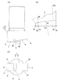
パンチプレスを用いて板材の切断、長孔の形成、孔開けを行う場合、通常は金型として横断面形状が長方形状のパンチ金型を用い、多数のパンチ孔を連続して加工する方法が採られる。この方法は、連続して開けられるパンチ孔の継ぎ目部分に、図15に示すように、板材Wの切断面100の上部が、ダレ101を形成せずに小さな突起状の痕跡102となって残るという問題がある。なお、図15(C)に示すように、パンチ加工による切断面100は、パンチ進入側から順に、ダレ101、せん断面103、破断面104となる。
When cutting a plate material, forming a long hole, or drilling using a punch press, there is usually a method in which a punch die having a rectangular cross section is used as the die and a large number of punch holes are continuously processed. Taken. In this method, as shown in FIG. 15, the upper portion of the
このような継ぎ目部分の痕跡102を無くすパンチ加工方法として、底面が水平に対し傾斜した切込刃部を有する追切り切断用パンチ金型を用い、前記切込刃部では板材を打抜かずに切込みを入れるだけとして、次の切込みを前の切込みに続けて加工する方法が提案されている(例えば特許文献1,2)。このように切込みを順次入れる加工方法によると、切断面が連続して綺麗に仕上がる。なお、これら提案の追切り切断用パンチ金型は、切込刃部とは別に打抜刃部を有し、この打抜刃部により、前記のパンチ加工で切込刃部により形成された切込みの内側部分を打抜くようになっている。
As a punching method for eliminating
上記従来の追切り切断用パンチ金型は、切込刃部に一定の切込角度が付けられているため、切込みの基端でもダレがある程度は形成される。そのため、追切り切断の末端等において、切込みが未形成な箇所と切込みが入れられ箇所とを、横断面形状が長方形状の一般的なパンチ金型で打抜く場合、追切り切断用パンチ金型で形成された切込みと一般的なパンチ金型で形成されたパンチ孔との継ぎ目部分に、一般的なパンチ金型だけを用いてパンチ孔を連続して加工する場合より程度は小さいものの、上記と同様の突起状の痕跡102(図15)が残る。 Since the above-mentioned conventional cutting die for additional cutting has a fixed cutting angle at the cutting blade portion, a certain amount of sagging is formed even at the base end of the cutting. Therefore, in the case of punching the portion where the cut is not formed and the portion where the cut is made with a general punch die having a rectangular cross section at the end of the cut-off cutting, etc. Although the degree is smaller than the case where the punch holes are continuously processed using only a general punch die at the joint portion between the incision formed with the punch hole formed with the general punch die, the above-mentioned A protruding mark 102 (FIG. 15) similar to that of FIG.
また、追切り切断用パンチ金型を用いて板材に矩形の開口を形成する場合、従来は図16に示す方法が採られていた。すなわち、目標とする開口110のコーナー部に一般的なパンチ金型を用いて捨て孔111を開け(同図(A))、この捨て孔111に続き、追切り切断用パンチ金型を用いて隣合う捨て孔111に向けて追切り切断し(同図(B))、切込刃部で形成される切込み112を隣合う捨て孔111に繋げることで、開口110の1辺を切断する(同図(C))。なお、前回のパンチ加工で形成された切込み112の内側部分は、打抜刃部により打抜かれ、その打抜き孔が繋がることで長孔113が形成される。図では、開口110の1辺だけを切断した状態を示しているが、他の3辺についても同様に切断することにより、開口110が形成される。この開口形成方法によると、捨て孔111と、この捨て孔111に続いて形成される切込み112との継ぎ目部分に、突起状の痕跡102(図15)が残る。
In the case where a rectangular opening is formed in a plate material using a punching die for additional cut, a method shown in FIG. 16 has been conventionally employed. That is, a common punch mold is used to open a
この発明の目的は、板材に追切りを行って切断、長孔の形成、開口の形成等をする場合に、パンチ加工の継ぎ目部分に突起状の痕跡がほとんど残らず、しかも切抜き切断の末端等においても突起状の痕跡をほとんど残さずに加工できるパンチプレスの追切り切断用パンチ金型を提供することである。
この発明の他の目的は、追切り切断用パンチ金型によるパンチ加工時に同パンチ金型の切込刃部によって板材に生じる応力を板材の面に沿って連続的に変化させ、応力の加わる範囲とそうでない範囲との境界点を集中して発生させないようにすることである。
この発明のさらに他の目的は、板材に対し定められたコーナー形状に切込みを入れることができ、その切込みと追切り切断用パンチ金型の切込刃部による切込みの継ぎ目部分に突起状の痕跡がほとんど残らないパンチプレスのコーナー切断用パンチ金型を提供することである。
この発明のさらに他の目的は、板材に矩形等のコーナー部を有する開口を開ける場合に組み合わせて用いるのに適したパンチプレスの追切り切断用・コーナー切断用パンチ金型組を提供することである。
この発明のさらに他の目的は、板材に矩形等のコーナー部を有する開口を、切込みの継ぎ目部分に突起状の痕跡をほとんど残さずに形成することができる開口形成方法を提供することである。
The object of the present invention is to cut the plate material by cutting, forming a long hole, forming an opening, etc., and there is almost no protruding trace at the joint portion of punching, and the end of the cut and cut Is to provide a punch die for additional cut of a punch press that can be processed with almost no protruding traces remaining.
Another object of the present invention is to continuously change the stress generated in the plate material along the surface of the plate material by the cutting blade portion of the punch die at the time of punching by the punch die for additional cut, and the range in which the stress is applied. It is to prevent the boundary points between the range and the range not to be generated in a concentrated manner.
Still another object of the present invention is to make a cut in a predetermined corner shape with respect to a plate material, and a projecting trace at the joint portion of the cut by the cut blade portion of the cut die for additional cut. It is to provide a punch die for cutting a corner of a punch press that hardly remains.
Still another object of the present invention is to provide a punch die set for additional cutting and corner cutting of a punch press suitable for use in combination when opening an opening having a corner portion such as a rectangle on a plate material. is there.
Still another object of the present invention is to provide an opening forming method capable of forming an opening having a corner portion such as a rectangle in a plate material, leaving almost no protruding traces at a cut seam portion.
この発明のパンチプレスの追切り切断用パンチ金型は、板材に追切りを行って連続する切断線に沿って切断するためのものであって、追切り方向に並んで配置され、互いに側面が同一面上に位置してそれぞれの側面の下端縁が打抜エッジおよび切込エッジとされた打抜刃部および切込刃部を有し、前記打抜刃部は、前記切込刃部よりも下方に段差を持って突出し、前記切込刃部は、底面が前記打抜刃部から遠ざかるに従い上方に傾斜し、この底面における前記打抜刃部と前記切込刃部の並び方向の中間部が、上方に窪む側面形状の凹部とされ、この凹部の側面形状の輪郭線は、前記打抜刃部から遠ざかるに従って水平に対する傾斜角度が小さくなる形状であることを特徴とする。 The punch die for additional cutting of the punch press according to the present invention is for cutting a plate material along a continuous cutting line, arranged side by side in the additional cutting direction, and the side surfaces thereof are mutually It has a punching blade portion and a cutting blade portion, which are located on the same plane and whose lower end edge of each side surface is a punching edge and a cutting edge, and the punching blade portion is formed from the cutting blade portion. And the cutting blade portion is inclined upward as the bottom surface is moved away from the punching blade portion, and the cutting blade portion and the cutting blade portion on the bottom surface are arranged in an intermediate direction. The portion is a side-shaped concave portion that is recessed upward, and the side-line contour line of the concave portion has a shape in which the inclination angle with respect to the horizontal decreases as the distance from the punching blade portion increases.
この構成の追切り切断用パンチ金型は、このパンチ金型に対応するダイ金型と共に使用される。ダイ金型の上に板材を載置し、この板材に対しパンチ金型を打ち下ろしてパンチ加工を行う。このパンチ加工により、板材に切込刃部の切込エッジで切込みが形成される。板材における切込みの内側部分、すなわち切込刃部の下側に位置する部分は、切込刃部の底面により下方に押し下げられて、先端側すなわち打抜刃部の側ほど下方に撓んだ切込片となる。この切込片は、基端すなわち打抜刃部に対する反対側端で切込みが未形成の箇所と繋がっている。前回のパンチ加工で形成された切込片の先端部を打抜刃部で打抜くように、前記切断線に沿ってパンチ金型の位置をずらせながらパンチ加工を繰り返し行うことにより、各パンチ加工の切込みが連なり切断線に沿って板材が切断される。また、各回のパンチ加工で打抜刃部によって打抜かれた部分が連なって、切断線に沿う長孔が形成される。 The punch cutting die having this configuration is used together with a die die corresponding to the punch die. A plate material is placed on the die mold, and punching is performed on the plate material by punching down the punch mold. By this punching process, a cut is formed in the plate material at the cutting edge of the cutting blade portion. The inner part of the cut in the plate material, that is, the part located below the cutting blade part is pushed downward by the bottom surface of the cutting blade part, and the cutting is bent downward toward the tip side, that is, the punching blade part side. It becomes a piece. This cut piece is connected to the base end, that is, the opposite end to the punching blade portion, where the cut is not formed. Each punching process is performed by repeatedly punching while shifting the position of the punch die along the cutting line so that the tip of the cutting piece formed by the previous punching process is punched by the punching blade part. The plate material is cut along the cutting line. Further, the portions punched by the punching blade portion in each punching process are connected to form a long hole along the cutting line.
切込刃部の底面の凹部は、その側面形状の輪郭線が、打抜刃部から遠ざかるに従って水平に対する傾斜角度が小さくなる形状とされている。そのため、凹部における打抜刃部から遠い側では、傾斜角度が小さく水平に近くなっている。したがって、凹部の打抜刃部から遠く離れた箇所がパンチ加工前の板材の上面の高さになるようにパンチ金型の打ち下ろし高さを設定することにより、切込刃部の底面に凹部が無いパンチ金型でパンチ加工する場合と比べて、パンチ加工で形成される切込片の基端を水平に近くすることができる。切込片の基端が水平に近ければ、切込みの基端でダレがほとんど生じない。そのため、追切り切断を行う場合に、切込みの継ぎ目部分に突起状の痕跡がほとんど残らない。 The concave portion on the bottom surface of the cutting blade portion has a shape in which the inclination angle with respect to the horizontal becomes smaller as the contour line of the side surface shape moves away from the punching blade portion. Therefore, on the side of the recess that is far from the punching blade, the inclination angle is small and close to horizontal. Therefore, by setting the punching die down height so that the portion far from the punching blade portion of the recess is the height of the top surface of the plate material before punching, the recess is formed on the bottom surface of the cutting blade portion. The base end of the cut piece formed by punching can be made nearly horizontal compared to the case of punching with a punch die having no punch. If the base end of the cut piece is close to the horizontal, there is almost no sagging at the base end of the cut. Therefore, when performing cut-off cutting, almost no protruding traces remain in the joint portion of the cut.
この発明のパンチプレスの追切り切断用パンチ金型において、前記切込刃部の底面の凹部は、前記並び方向の両側に続く斜面部分に対して、それぞれ下向きに凸状の曲面部分を介して互いに滑らかに繋がっているのが良い。なお、「滑らかに繋がる」とは、断面を成す曲線が接続部分で微分可能な形状であることを言う。
切込刃部の底面における凹部とその両側に続く部分とが滑らかに繋がっていれば、追切り切断用パンチ金型によるパンチ加工時に同パンチ金型の切込刃部によって板材に生じる応力が、板材の面に沿って連続的に変化した状態にできる。すなわち、応力の加わる範囲とそうでない範囲との境界点を集中して発生させない。それにより、板材が定められた形状以外に変形することを防げる。
In the punch die for additional cut of the punch press according to the present invention, the concave portions on the bottom surface of the cutting blade portion are respectively provided through curved surface portions that are convex downward with respect to the slope portions continuing on both sides in the arrangement direction. It is good that they are connected smoothly. Note that “smoothly connected” means that the curve forming the cross section has a shape that can be differentiated at the connecting portion.
If the concave portion on the bottom surface of the cutting blade portion and the portions continuing on both sides thereof are smoothly connected, the stress generated in the plate material by the cutting blade portion of the punch die during punching with the punch die for additional cutting, The state can be changed continuously along the surface of the plate. That is, the boundary points between the range where the stress is applied and the range where the stress is not applied are not concentrated. Thereby, it can prevent that a board | plate material deform | transforms into shapes other than the defined shape.
この発明のパンチプレスのコーナー切断用パンチ金型は、板材を定められたコーナー形状に沿って切断するためのものであって、外側面の下端縁が前記コーナー形状に沿う打抜エッジとされた打抜刃部と、一側面の下端縁が前記打抜エッジの両端にそれぞれ続き平面形状で打抜エッジの延長方向へ延びる切込エッジとされた2つの切込刃部とを有し、前記打抜刃部は、前記切込刃部よりも下方に突出し、前記切込刃部は、底面が前記打抜刃部から遠ざかるに従い上方に傾斜し、この底面における前記打抜刃部と前記切込刃部の並び方向の中間部が、上方に窪む側面形状の凹部であり、この凹部の側面形状の輪郭線は、前記打抜刃部から遠ざかるに従って水平に対する傾斜角度が小さくなる形状であることを特徴とする。 The punch die for cutting a corner of the punch press according to the present invention is for cutting a plate material along a predetermined corner shape, and the lower end edge of the outer surface is a punching edge along the corner shape. A punching blade portion, and two cutting blade portions each having a cutting edge extending in the extending direction of the punching edge in a planar shape with the lower end edge of one side surface extending from both ends of the punching edge, The punching blade portion protrudes downward from the cutting blade portion, and the cutting blade portion is inclined upward as the bottom surface moves away from the punching blade portion. The intermediate portion in the direction in which the blades are arranged is a concave portion having a side shape that is recessed upward, and the contour line of the side surface shape of the concave portion has a shape in which the inclination angle with respect to the horizontal decreases as the distance from the punching blade portion increases. It is characterized by that.
この構成のコーナー切断用パンチ金型は、このパンチ金型に対応するダイ金型と組み合わせて使用される。ダイ金型の上に板材を載置し、この板材に対しパンチ金型を打ち下ろしてパンチ加工を行う。このパンチ加工により、板材に打抜刃部の打抜エッジおよび切込刃部の切込エッジでコーナー形状の切込みが形成される。板材における切込みの内側部分、すなわち打抜刃部および切込刃部の下側に位置する部分は、両刃部の底面により下方に押し下げられて、撓み形状の切込片となる。この切込片は、基端すなわちコーナーに対する反対側端で切込みが未形成の箇所と繋がっている。 The corner cutting punch mold having this configuration is used in combination with a die mold corresponding to the punch mold. A plate material is placed on the die mold, and punching is performed on the plate material by punching down the punch mold. By this punching process, a corner-shaped cut is formed in the plate material by the punching edge of the punching blade portion and the cutting edge of the cutting blade portion. The inner part of the cut in the plate material, that is, the part located below the punching blade part and the cutting blade part is pushed downward by the bottom surfaces of the two blade parts to form a bending-shaped cutting piece. This cut piece is connected to the base end, that is, the opposite end with respect to the corner, where the cut is not formed.
切込刃部の底面の凹部は、その側面形状の輪郭線が、打抜刃部から遠ざかるに従って水平に対する傾斜角度が小さくなる形状とされている。そのため、凹部における打抜刃部から遠い側では、傾斜角度が小さく水平に近くなっている。したがって、凹部の打抜刃部から遠く離れた箇所がパンチ加工前の板材の上面の高さになるようにパンチ金型の打ち下ろし高さを設定することにより、切込刃部の底面に凹部を有しないパンチ金型でパンチ加工する場合と比べて、パンチ加工で形成される切込片の基端を水平に近くすることができる。切込片の基端が水平に近ければ、追切り切断用パンチ金型で追切りを行う場合に、切込みの基端でダレがほとんど生じない。そのため、コーナー切断用パンチ金型による切込みと追切り切断用パンチ金型による切込みとの継ぎ目部分に、突起状の痕跡がほとんど残らない。 The concave portion on the bottom surface of the cutting blade portion has a shape in which the inclination angle with respect to the horizontal becomes smaller as the contour line of the side surface shape moves away from the punching blade portion. Therefore, on the side of the recess that is far from the punching blade, the inclination angle is small and close to horizontal. Therefore, by setting the punching die down height so that the portion far from the punching blade portion of the recess is the height of the top surface of the plate material before punching, the recess is formed on the bottom surface of the cutting blade portion. The base end of the cut piece formed by punching can be made almost horizontal compared to the case of punching with a punch die having no. If the base end of the cut piece is close to the horizontal, there is almost no sagging at the base end of the cut when performing the post-cutting with the punching die for cut-off cutting. Therefore, almost no protruding traces remain at the joint between the cut by the corner cutting punch mold and the cut by the additional cutting punch mold.
この発明のパンチプレスの追切り切断用・コーナー切断用パンチ金型組は、請求項1または請求項2に記載のパンチプレスの追切り切断用パンチ金型と、パンチプレスのコーナー切断用パンチ金型とでなる金型組である。前記コーナー切断用パンチ金型は、外側面の下端縁が定められたコーナー形状に沿う打抜エッジとされた打抜刃部と、一側面の下端縁が前記打抜エッジの両端にそれぞれ続き平面形状で打抜エッジの延長方向へ延びる切込エッジとされた2つの切込刃部とを有し、前記打抜刃部は、前記切込刃部よりも下方に突出し、前記切込刃部は、底面が前記打抜刃部から遠ざかるに従い上方に傾斜し、この底面における前記打抜刃部と前記切込刃部の並び方向の中間部が、上方に窪む側面形状の凹部であり、この凹部の側面形状の輪郭線は、前記打抜刃部から遠ざかるに従って水平に対する傾斜角度が小さくなる形状である。
追切り切断用パンチ金型とコーナー切断用パンチ金型とを組み合わせて使用することにより、板材に矩形等の開口を効率良く形成することができ、形成された開口の辺の部分およびコーナー部のいずれにも突起状の痕跡がほとんど残らない綺麗な仕上がりとすることができる。
A punch die set for additional cutting and corner cutting of a punch press according to the present invention includes a punch die for additional cutting of a punch press according to
By using a combination of a punch die for additional cutting and a corner cutting punch die, an opening such as a rectangle can be efficiently formed in the plate material, and the side portion of the formed opening and the corner portion In any case, it is possible to obtain a beautiful finish with almost no protruding traces remaining.
この発明の板材の開口形成方法は、請求項1または請求項2に記載の追切り切断用パンチ金型、および請求項3に記載のコーナー切断用パンチ金型を用いる方法であって、コーナー切断過程、追切り準備過程、追切り過程、および打抜き過程を含む。前記コーナー切断過程は、板材に形成しようとする開口のコーナーとなる箇所に前記コーナー切断用パンチ金型を用いてパンチ加工を行い、同パンチ金型の打抜刃部および切込み刃部により板材にコーナー切込みを形成し、そのコーナー切込みの内側部分を下方に押し下げてコーナー切込片とする過程である。前記追切り準備過程は、前記コーナー切込片に前記追切り切断用パンチ金型の打抜刃部が上下に重なり、かつ同パンチ金型の切込刃部が打抜刃部よりもコーナーから離れて位置するように配置した前記追切り切断用パンチ金型を用いてパンチ加工を行い、同パンチ金型の打抜刃部により前記コーナー切込片を打抜き、かつ同パンチ金型の切込刃部により、前記コーナー切込みに続いてコーナーから離れる側へ延びる追切り切込みを形成し、その追切り切込みの内側部分を下方に押し下げて追切り切込片とする過程である。前記追切り過程は、前記追切り準備過程に続いて複数回繰り返し行われ、前記追切り準備過程または前回の追切り過程において形成された追切り切込み片に前記追切り切断用パンチ金型の打抜刃部が上下に重なり、かつ同パンチ金型の切込刃部が打抜刃部よりもコーナーから離れて位置するように配置した前記追切り切断用パンチ金型を用いてパンチ加工を行い、同パンチ金型の打抜刃部により前記追切り切込片を打抜き、かつ同パンチ金型の切込刃部により、前記追切り切込みに続いてコーナーから離れる側へ延びる新たな追切り切込みを形成し、その追切り切込みの内側部分を下方に押し下げて新たな追切り切込片とする過程である。前記打抜き過程は、隣合う2つのコーナーから両コーナー間の中央側に向かって前記コーナー切断過程、追切り準備過程、および追切り過程を順に行って、両方向の最後に行われた追切り過程によってそれぞれ形成された未切断の箇所を、前記追切り切断用パンチ金型およびコーナー切断用パンチ金型とは別の打抜用パンチ金型を用いて打抜く打抜き過程である。
The plate material opening forming method according to the present invention is a method using the cut-off punch die according to
この板材の開口形成方法によると、まずコーナー切断過程により、板材に形成しようとする開口のコーナーとなる箇所にコーナー切断用パンチ金型を用いてパンチ加工を行う。それにより、同パンチ金型の打抜刃部の打抜エッジおよび切込刃部の切込エッジで板材にコーナー形状のコーナー切込みを形成し、そのコーナー切込みの内側部分を打抜刃部および切込刃部の底面で下方に押し下げて、コーナー切込片とする。このパンチ加工時、切込刃部の底面の凹部における打抜刃部から遠く離れた箇所がパンチ加工前の板材の上面の高さになるようにパンチ金型の打ち下ろし高さを設定しておくことで、コーナー切込片の基端が水平に近くなる。 According to this opening formation method for a plate material, first, a corner cutting process is used to perform punch processing at a portion that becomes a corner of an opening to be formed in a plate material using a corner cutting punch mold. As a result, a corner-shaped corner cut is formed in the plate material by the punching edge of the punching blade portion and the cutting edge of the cutting blade portion of the punch die, and the inner portion of the corner cut is formed by the punching blade portion and the cutting edge. Push down downward on the bottom of the cutting edge to make a corner cut piece. At the time of punching, set the punch die down height so that the part far from the punching blade in the recess at the bottom of the cutting blade is the height of the top surface of the plate before punching. By placing it, the base end of the corner cut piece becomes almost horizontal.
次に、追切り準備過程により、前記コーナー切断過程において形成されたコーナー切込片に打抜刃部が上下に重なり、かつ切込刃部が打抜刃部よりもコーナーから離れて位置するように配置した追切り切断用パンチ金型を用いてパンチ加工を行う。それにより、同パンチ金型の打抜刃部でコーナー切込片を打抜き、同パンチ金型の切込刃部の切込エッジで前記コーナー切込みに続いてコーナーから離れる側へ延びる追切り切込みを形成し、その追切り切込みの内側部分を切込刃部の底面で下方に押し下げて追切り切込片とする。前記コーナー切断過程において形成されたコーナー切込片の基端が水平に近いため、追切り準備過程で追切り切断用パンチ金型を用いて追切りを行う場合に、コーナー切込みの基端でダレがほとんど生じない。そのため、コーナー切断用パンチ金型によるコーナー切込みと追切り切断用パンチ金型による追切り切込みとの継ぎ目部分に、突起状の痕跡がほとんど残らない。 Next, in the additional cut preparation process, the punching blade portion overlaps with the corner cutting piece formed in the corner cutting process, and the cutting blade portion is positioned farther from the corner than the punching blade portion. Punching is performed using a punching die for additional cut arranged in the above. As a result, a corner cutting piece is punched with the punching blade portion of the punch die, and a cutting edge extending toward the side away from the corner following the corner cutting at the cutting edge of the cutting blade portion of the punch die. Then, the inner portion of the additional cut is pushed downward on the bottom surface of the cutting blade portion to form a additional cut piece. Since the base end of the corner cut piece formed in the corner cutting process is nearly horizontal, when the additional cutting is performed using the punch die for the additional cut in the additional cut preparation process, Hardly occurs. Therefore, almost no protruding traces remain at the joint between the corner cut by the corner cutting punch mold and the additional cut by the additional cut punch mold.
追切り準備過程に続いて、目標とする切断線に沿って位置をずらせながら追切り過程を複数回繰り返し行う。追切り過程は、追切り切断用パンチ金型を、打抜刃部が追切り準備過程または前回の追切り過程において形成された追切り切込片に上下に重なり、かつ切込刃部が打抜刃部よりもコーナーから離れて位置するように配置して、パンチ加工を行うものである。この追切り過程により、同パンチ金型の打抜刃部で前回形成された追切り切込片を打抜き、かつ切込刃部の切込エッジで前回形成された追切り切込みに続いてコーナーから離れる側へ延びる新たな追切り切込みを形成し、その追切り切込みの内側部分を切込刃部の下面で下方に押し下げて新たな追切り切込片とする。このパンチ加工時、切込刃部の底面の凹部における打抜刃部から遠く離れた箇所がパンチ加工前の板材の上面の高さになるようにパンチ金型の打ち下ろし高さを設定することで、追切り切込片の基端を水平に近くする。それにより、追切り切込みの基端でダレがほとんど生じず、追切り切込みの継ぎ目部分に突起状の痕跡がほとんど残らない。 Following the cut-off preparation process, the cut-off process is repeated a plurality of times while shifting the position along the target cutting line. In the cut-off process, the punching die for the cut-off cutting is overlapped with the cut-off cutting piece formed in the cut-off preparation part or the previous cut-off process and the cutting blade part is punched. The punching process is performed by disposing it so as to be positioned farther from the corner than the punching blade portion. By this additional cutting process, the additional cutting piece previously formed by the punching blade part of the same punching die is punched, and from the corner following the additional cutting formed previously by the cutting edge of the cutting blade part. A new additional cut is formed that extends to the far side, and the inner portion of the additional cut is pushed downward on the lower surface of the cutting blade to form a new additional cut. At the time of punching, set the punch die down height so that the part far from the punching blade in the recess at the bottom of the cutting blade is the height of the top surface of the plate before punching Then, make the base end of the additional cut piece close to the horizontal. As a result, almost no sagging occurs at the base end of the additional cut, and almost no protruding traces remain at the joint of the additional cut.
上記コーナー切断過程、追切り準備過程、および追切り過程を、隣合う2つのコーナーから両コーナー間の中央側に向かって順に行って、コーナー間の各辺の中央部に未切断の箇所が残された状態とする。未切断の箇所の両側は、両方向の最後に行われた追切り過程によってそれぞれ形成された一対の追切り切込片となっている。そして、打抜き過程により、上記未切断の箇所を、追切り切断用パンチ金型およびコーナー切断用パンチ金型とは別の打抜用パンチ金型を用いて打抜くことで、開口を完成する。上記最後に行われた追切り過程によってそれぞれ形成された追切り切込みの基端でダレがほとんど生じていないため、打抜用パンチ金型で追切り切込片を打抜く場合も、追切り切込みと打抜用パンチ金型によるパンチ孔との継ぎ目部分に、突起状の痕跡がほとんど残らない。 The above corner cutting process, additional cutting preparation process, and additional cutting process are performed in order from the two adjacent corners toward the center between both corners, leaving an uncut portion at the center of each side between the corners. It is assumed that Both sides of the uncut portion are a pair of additional cut pieces formed by the final cut process performed at the end in both directions. In the punching process, the uncut portion is punched using a punching die other than the post-cutting punch die and the corner cutting punch die, thereby completing the opening. Since there is almost no sag at the base end of each additional cut formed by the last cut process, the additional cut is also performed when punching the additional cut piece with a punching die. There is almost no protruding trace at the joint between the punch hole and the punch hole by the punching die.
この発明のパンチプレスの追切り切断用パンチ金型は、板材に追切りを行って連続する切断線に沿って切断するためのものであって、追切り方向に並んで配置され、互いに側面が同一面上に位置してそれぞれの側面の下端縁が打抜エッジおよび切込エッジとされた打抜刃部および切込刃部を有し、前記打抜刃部は、前記切込刃部よりも下方に段差を持って突出し、前記切込刃部は、底面が前記打抜刃部から遠ざかるに従い上方に傾斜し、この底面における前記打抜刃部と前記切込刃部の並び方向の中間部が、上方に窪む側面形状の凹部とされ、この凹部の側面形状の輪郭線は、前記打抜刃部から遠ざかるに従って水平に対する傾斜角度が小さくなる形状であるため、板材に追切りを行って切断、長孔の形成、開口の形成等をする場合に、パンチ加工の継ぎ目部分に突起状の痕跡がほとんど残らず、しかも切抜き切断の末端等においても突起状の痕跡をほとんど残さずに加工できる。 The punch die for additional cutting of the punch press according to the present invention is for cutting a plate material along a continuous cutting line, arranged side by side in the additional cutting direction, and the side surfaces thereof are mutually It has a punching blade portion and a cutting blade portion, which are located on the same plane and whose lower end edge of each side surface is a punching edge and a cutting edge, and the punching blade portion is formed from the cutting blade portion. And the cutting blade portion is inclined upward as the bottom surface is moved away from the punching blade portion, and the cutting blade portion and the cutting blade portion on the bottom surface are arranged in an intermediate direction. The side portion is a concave portion that is recessed upward, and the contour line of the side surface shape of this concave portion has a shape in which the inclination angle with respect to the horizontal decreases as the distance from the punching blade portion increases, so the plate material is additionally cut. When cutting, forming long holes, forming openings, etc. Most left without trace of protruding in the joint portions of the machining, moreover it can be processed without leaving little protruding traces even at the end or the like of the cut-out cutting.
上記パンチプレスの追切り切断用パンチ金型において、前記切込刃部の底面の凹部が、前記並び方向の両側に続く斜面部分に対して、それぞれ下向きに凸状の曲面部分を介して互いに滑らかに繋がっていれば、追切り切断用パンチ金型によるパンチ加工時に同パンチ金型の切込刃部によって板材に生じる応力を板材の面に沿って連続的に変化させ、応力の加わる範囲とそうでない範囲との境界点を集中して発生させない。 In the punch die for additional cut of the punch press, the concave portions on the bottom surface of the cutting blade portion are smoothed with respect to the slope portions continuing on both sides in the alignment direction, respectively, via downward curved surface portions. If it is connected to, the stress generated in the plate material by the cutting blade part of the punch die at the time of punching by the punch die for additional cut is continuously changed along the surface of the plate material, so that the stress is applied. Do not concentrate the boundary points with non-range.
この発明のパンチプレスのコーナー切断用パンチ金型は、板材を定められたコーナー形状に沿って切断するためのものであって、外側面の下端縁が前記コーナー形状に沿う打抜エッジとされた打抜刃部と、一側面の下端縁が前記打抜エッジの両端にそれぞれ続き平面形状で打抜エッジの延長方向へ延びる切込エッジとされた2つの切込刃部とを有し、前記打抜刃部は、前記切込刃部よりも下方に突出し、前記切込刃部は、底面が前記打抜刃部から遠ざかるに従い上方に傾斜し、この底面における前記打抜刃部と前記切込刃部の並び方向の中間部が、上方に窪む側面形状の凹部であり、この凹部の側面形状の輪郭線は、前記打抜刃部から遠ざかるに従って水平に対する傾斜角度が小さくなる形状であるため、板材に対し定められたコーナー形状に切込みを入れることができ、その切込みと追切り切断用パンチ金型の切込刃部による切込みの継ぎ目部分に痕跡がほとんど残らない。 The punch die for cutting a corner of the punch press according to the present invention is for cutting a plate material along a predetermined corner shape, and the lower end edge of the outer surface is a punching edge along the corner shape. A punching blade portion, and two cutting blade portions each having a cutting edge extending in the extending direction of the punching edge in a planar shape with the lower end edge of one side surface extending from both ends of the punching edge, The punching blade portion protrudes downward from the cutting blade portion, and the cutting blade portion is inclined upward as the bottom surface moves away from the punching blade portion. The intermediate portion in the direction in which the blades are arranged is a concave portion having a side shape that is recessed upward, and the contour line of the side surface shape of the concave portion has a shape in which the inclination angle with respect to the horizontal decreases as the distance from the punching blade portion increases. Therefore, the corner shape defined for the plate material Can contain cut, hardly remains trace the joint portion of the cut by the cutting blade portion of the cut and add cut cutting punch.
この発明のパンチプレスの追切り切断用・コーナー切断用パンチ金型組は、請求項1または請求項2に記載のパンチプレスの追切り切断用パンチ金型と、パンチプレスのコーナー切断用パンチ金型とでなる金型組であって、前記コーナー切断用パンチ金型は、外側面の下端縁が定められたコーナー形状に沿う打抜エッジとされた打抜刃部と、一側面の下端縁が前記打抜エッジの両端にそれぞれ続き平面形状で打抜エッジの延長方向へ延びる切込エッジとされた2つの切込刃部とを有し、前記打抜刃部は、前記切込刃部よりも下方に突出し、前記切込刃部は、底面が前記打抜刃部から遠ざかるに従い上方に傾斜し、この底面における前記打抜刃部と前記切込刃部の並び方向の中間部が、上方に窪む側面形状の凹部であり、この凹部の側面形状の輪郭線は、前記打抜刃部から遠ざかるに従って水平に対する傾斜角度が小さくなる形状であるため、板材に矩形等のコーナー部を有する開口を開ける場合に組み合わせて用いるのに適する。
The punch die set for additional cutting and corner cutting of the punch press according to the present invention includes a punch die for additional cutting of the punch press according to
この発明の板材の開口形成方法は、請求項1または請求項2に記載の追切り切断用パンチ金型、および請求項3に記載のコーナー切断用パンチ金型を用いるパンチプレスによる板材の開口形成方法であって、コーナー切断過程、追切り準備過程、追切り過程、および打抜き過程を含み、前記コーナー切断過程は、板材に形成しようとする開口のコーナーとなる箇所に前記コーナー切断用パンチ金型を用いてパンチ加工を行い、同パンチ金型の打抜刃部および切込み刃部により板材にコーナー切込みを形成し、そのコーナー切込みの内側部分を下方に押し下げてコーナー切込片とする過程であり、前記追切り準備過程は、前記コーナー切込片に前記追切り切断用パンチ金型の打抜刃部が上下に重なり、かつ同パンチ金型の切込刃部が打抜刃部よりもコーナーから離れて位置するように配置した前記追切り切断用パンチ金型を用いてパンチ加工を行い、同パンチ金型の打抜刃部により前記コーナー切込片を打抜き、かつ同パンチ金型の切込刃部により、前記コーナー切込みに続いてコーナーから離れる側へ延びる追切り切込みを形成し、その追切り切込みの内側部分を下方に押し下げて追切り切込片とする過程であり、前記追切り過程は、前記追切り準備過程に続いて複数回繰り返し行われ、前記追切り準備過程または前回の追切り過程において形成された追切り切込み片に前記追切り切断用パンチ金型の打抜刃部が上下に重なり、かつ同パンチ金型の切込刃部が打抜刃部よりもコーナーから離れて位置するように配置した前記追切り切断用パンチ金型を用いてパンチ加工を行い、同パンチ金型の打抜刃部により前記追切り切込片を打抜き、かつ同パンチ金型の切込刃部により、前記追切り切込みに続いてコーナーから離れる側へ延びる新たな追切り切込みを形成し、その追切り切込みの内側部分を下方に押し下げて新たな追切り切込片とする過程であり、前記打抜き過程は、隣合う2つのコーナーから両コーナー間の中央側に向かって前記コーナー切断過程、追切り準備過程、および追切り過程を順に行って、両方向の最後に行われた追切り過程によってそれぞれ形成された未切断の箇所を、前記追切り切断用パンチ金型およびコーナー切断用パンチ金型とは別の打抜用パンチ金型を用いて打抜く打抜き過程であるため、板材に矩形等のコーナー部を有する開口を、切込みの継ぎ目部分に痕跡をほとんど残さずに形成することができる。
The plate material opening forming method according to the present invention includes forming a plate material opening by a punch press using the punching die for additional cut according to
この発明の実施形態を図面と共に説明する。
図1はこの発明の一実施形態にかかるパンチプレスの追切り切断用パンチ金型を示す。この追切り切断用パンチ金型1は、柄部2の下端に刃部3が設けられている。刃部3は横断面形状が長方形状であり、刃部3の下端に、幅広方向つまり追切り方向に互いに並ぶ打抜刃部4と切込刃部5とが形成されている。したがって、打抜刃部4と切込刃部5とは、互いに同じ厚みで、両側面がそれぞれ同一平面となっている。打抜刃部4と切込刃部5との間には、両側面に抜ける溝状の逃がし凹部6が形成されている。逃がし凹部6の打抜刃部4側の内壁面6aは鉛直方向に沿う面であり、切込刃部5側の内壁面6bは下端側ほど切込刃部5に近づく傾斜面である。
An embodiment of the present invention will be described with reference to the drawings.
FIG. 1 shows a punch die for additional cut of a punch press according to an embodiment of the present invention. This additional
打抜刃部4の底面7は、同じ高さの平面状であって、底面7の各辺である下端縁が打抜エッジ8とされている。打抜刃部4は、切込刃部5の最下端よりも下方に段差Hを持って突出している。
The
切込刃部5の底面9は、打抜刃部4から遠ざかるに従い上方に傾斜しており、この底面9における打抜刃部4と切込刃部5の並び方向の、両端部を除く部分である中間部は、上方に窪む側面形状の凹部9aになっている。この凹部9aの側面形状の輪郭線は、打抜刃部4から遠ざかるに従って水平に対する傾斜角度が小さくなる形状である。具体的には、凹部9aの側面形状の輪郭線は、半径R1の円弧であり、その円弧の打抜刃部4と反対側端は限りなく水平に近い形状になっている。また、凹部9aは、前記並び方向の両側に続く斜面部分9b,9cに対して、それぞれ下向きに凸状の曲面部分9d,9eを介して互いに滑らかに繋がっている。これら曲面部分9d,9eの側面形状の輪郭線は、それぞれ半径R2,R3の円弧である。両斜面部分9b,9cは、互いに同一平面上に位置する。斜面部分9bから逃し凹部6までの間は、水平面部分9fとなっている。切込刃部5は、両側面の下端縁が切込エッジ10とされている。
The
図2は上記追切り切断用パンチ金型1と組み合わせて使用される追切り切断用ダイ金型を示す。この追切り切断用ダイ金型11は、平面形状が略円形のものであり、パンチ金型1の打抜刃部4および切込刃部5が進入するスリット状の刃部進入孔12が、上下に貫通して設けられている。この刃部進入孔12は、上孔部12aよりも下孔部12bの方が長手方向の長さが長い段付き孔であり、上孔部12aは、パンチ金型1の刃部3が嵌合する横断面形状とされている。上孔部12aの長手方向の一方の壁面は、上端部よりも下側の部分が外径側へ後退する傾斜面12aaとされている。刃部進入孔12は、長手方向すなわち追切り方向の中央部で仕切り壁13により仕切られて、一方の孔部分がパンチ金型1の打抜刃部4が進入する打抜用貫通孔14となり、もう一方の孔部分が後記板材Wの舌片状の追切り切込片96(図8(D))が落ち込む切込用貫通孔15となっている。仕切り壁13の打抜用貫通孔14側の壁面13aは鉛直方向に沿う面であり、切込用貫通孔15側の壁面13bは、追切り切断用パンチ金型1の逃がし凹部6の内壁面6bに対応する傾斜面である。
FIG. 2 shows a die for cutting-off cutting used in combination with the punching die 1 for cutting-off. This die for cutting 11 has a substantially circular planar shape, and has a slit-shaped blade
刃部進入孔12における打抜用貫通孔14の上方に位置する部分の上端縁、および仕切り壁13の打抜用貫通孔14側の壁面13aの上端縁は、追切り切断用パンチ金型1の前記打抜エッジ8と噛み合う打抜エッジ16となっている。また、刃部進入孔12における切込用貫通孔15の上方に位置する部分の追切り方向に沿う上端縁は、追切り切断用パンチ金型1の前記切込エッジ10と噛み合う切込用エッジ17となっている。
The upper end edge of the portion located above the punching through
図3はこの発明の一実施形態にかかるパンチプレスのコーナー切断用パンチ金型を示す。このコーナー切断用パンチ金型21は、柄部22の下端に刃部23が設けられている。刃部23は横断面形状がほぼ正方形で、刃部23の下端に、1つの打抜刃部24と2つの切込刃部25とが形成されている。刃部23と打抜刃部24とは、互いに接している。
FIG. 3 shows a punch die for corner cutting of a punch press according to an embodiment of the present invention. This corner cutting
打抜刃部24の底面26は、正方形からなる同じ高さの平面状であって、底面26の4辺のうち隣合う2辺に沿う下端縁が打抜エッジ27とされている。各切込刃部25の底面28は、前記打抜刃部24の打抜エッジ27でない2辺29Aにそれぞれ接し、また各切込刃部25の底面28同士は稜線状の境界線29Bで互いに接している。
The
切込刃部25の底面28は、打抜刃部24から遠ざかるに従い上方に傾斜しており、この底面28における打抜刃部24と切込刃部25の並び方向の、両端部を除く部分である中間部は、上方に窪む側面形状の凹部28aになっている。この凹部28aの側面形状の輪郭線は、打抜刃部24から遠ざかるに従って水平に対する傾斜角度が小さくなる形状である。具体的には、凹部28aの側面形状の輪郭線は、半径R4の円弧であり、その円弧の打抜刃部24と反対側端は限りなく水平に近い形状になっている。また、凹部28aは、前記並び方向の両側に続く斜面部分28b,28cに対して、それぞれ下向きに凸状の曲面部分28d,28eを介して互いに滑らかに繋がっている。これら曲面部分28d,28eの側面形状の輪郭線は、それぞれ半径R5,R6の円弧である。切込刃部25は、打抜刃部24の打抜エッジ27に続く下端縁が切込エッジ30とされている。
The
図4は上記コーナー切断用パンチ金型21と組み合わせて使用されるコーナー切断用ダイ金型を示す。このコーナー切断用ダイ金型31は、平面形状が略円形のものであり、パンチ金型21の打抜刃部24および切込刃部25が進入する平面形状ほぼ正方形の刃部進入孔32が、上下に貫通して設けられている。この刃部進入孔32は、上孔部32aよりも下孔部32bの方が平面形状の大きい段付きの孔であり、上孔部32aは、パンチ金型21の刃部23が嵌合する横断面形状とされている。上孔部32aの隣合う2つの壁面は、上端部よりも下側の部分が外径側へ後退する傾斜面32aaとされている。刃部進入孔32に上記隣合う2つの壁面32aaとは別の隣合う2辺の上端縁が、コーナー切断用パンチ金型21の前記打抜エッジ27および切込エッジ30とそれぞれ噛み合う打抜エッジ33および切込用エッジ34となっている。
FIG. 4 shows a corner cutting die mold used in combination with the above corner cutting
図5は打抜用パンチ金型、図6は打抜用ダイ金型を示す。これら打抜用パンチ金型41および打抜用ダイ金型51は、板材を長方形に打抜くための一般的なものである。打抜用パンチ金型41は、柄部42の下端に横断面形状が長方形状の刃部43が設けられている。刃部43の底面44の各辺である下端縁が打抜エッジ45とされている。図例では、底面44の正面形状の中央部が上方に窪む形状とされているが、底面44は水平な平面状であっても良い。打抜用ダイ金型51は、平面形状が略円形のものであり、パンチ金型41の刃部43が進入するスリット状の刃部進入孔52が、上下に貫通して設けられている。この刃部進入孔52は、上孔部52aよりも下孔部52bの方が長手方向の長さが長い段付き孔であり、上孔部52aは、パンチ金型41の刃部43が嵌合する横断面形状とされている。上下に貫通状態のスリット状の孔であり、刃部進入孔52の上端縁は、打抜用パンチ金型41の打抜エッジ45と噛み合う打抜エッジ53となっている。
FIG. 5 shows a punching die for punching, and FIG. 6 shows a die for punching. The punching die 41 for punching and the die die 51 for punching are general ones for punching a plate material into a rectangle. The punching die 41 for punching is provided with a
上記各パンチ金型1,21,41および各ダイ金型11,31,51は、パンチプレス(図示せず)に装着して使用される。パンチプレスにおける金型装着部の構造を、金型が追切り切断用パンチ金型1および追切り切断用ダイ金型11である場合を例にとって説明する。
The punch dies 1, 21, 41 and the die dies 11, 31, 51 are used by being mounted on a punch press (not shown). The structure of the die mounting portion in the punch press will be described by taking as an example the case where the die is the cut-off cutting die 1 and the cut-
図7において、追切り切断用パンチ金型1は、頭部部材61にセットボルト62で取付けられ、パンチホルダ63を介して上側のタレット64の金型設置孔65に昇降自在に嵌合している。頭部部材61は、そのT形の頭部でパンチ駆動機構(図示せず)のラム66に係合し、昇降駆動される。パンチ駆動機構は、クランク式のものであっても油圧式のものであっても良い。パンチホルダ63は昇降自在として押えばね67A,67Bにより下降付勢し、下端にストリッパ板68を取付けてある。
In FIG. 7, the punch cutting die 1 for cut-off is attached to the
追切り切断用パンチ金型1は、角度割り出し可能なインデックスツールとされている。すなわち、前記金型設置孔65はタレット本体64aに対し回転自在な回転体71に設けられている。回転体71は外周面にウォームホイール72を有し、このウォームホイール72に、タレット64の径方向に向けて配置した回転軸73に設けたウォームギア74が噛み合っている。駆動手段により回転軸73を回転させることにより、その回転がウォームギア74およびウォームホイール72を介して回転体71に伝達され、追切り切断用パンチ金型1が所望の角度に割り出される。
The post-cutting punch die 1 is an index tool capable of indexing. That is, the
追切り切断用ダイ金型11も、角度割り出し可能なインデックスツールとされている。すなわち、下側のタレット76に回転自在にダイホルダ77が装着され、このダイホルダ77に追切り切断用ダイ金型11が保持されている。ダイホルダ77は外周面にウォームホイール78を有し、このウォームホイール78に、タレット76の径方向に向けて配置した回転軸79に設けたウォームギア80が噛み合っている。駆動手段により回転軸79を回転させることにより、その回転がウォームギア80およびウォームホイール78を介してダイホルダ77に伝達され、追切り切断用ダイ金型11が所望の角度に割り出される。
The die for cutting 11 is also an index tool capable of indexing the angle. That is, the
上下のタレット64,76は、円周方向の複数個所にパンチ加工のための各種の金型を支持した金型支持部材であり、その設置金型の一つとして、追切り切断用パンチ金型1および追切り切断用ダイ金型11が設置されている。他のパンチ金型21,41およびダイ金型31,51も、上記同様に角度割り出し可能に設けられる。なお、これらの金型を設置するパンチプレスは、タレット式のものに限らず、パンチ金型およびダイ金型は、タレットとは別の金型支持部材(図示せず)に設置しても良い。
The upper and
追切り切断用パンチ金型1およびダイ金型11は、板材Wに追切りを行って切断や金型幅よりも長い長孔の形成を行うために用いられる。また、追切り切断用パンチ金型1およびダイ金型11をコーナー切断用パンチ金型21およびダイ金型31と併用することで、板材に矩形の開口を良好に形成することができる。追切り切断用パンチ金型1とコーナー切断用パンチ金型21の組合せは、追切り切断用・コーナー切断用パンチ金型組である。なお、この開口の形成には、打抜用パンチ金型41および打抜用ダイ金型51も併用される。
The post-cutting punch die 1 and the die die 11 are used for making a cut on the plate material W to form a long hole longer than the cutting or die width. Further, by using the punch cutting die 1 and the die die 11 in combination with the corner cutting punch die 21 and the die die 31, a rectangular opening can be satisfactorily formed in the plate material. The combination of the post-cutting cutting die 1 and the corner cutting punch die 21 is a post-cutting / corner cutting punch die set. For forming the opening, a punching die 41 for punching and a
次に、上記各金型を使用して行うパンチプレスによる板材の開口形成方法について説明する。図8(A)に示すように、板材Wに長方形の開口90を形成する場合を例にする。この板材の開口形成方法は、予備の開口形成過程、コーナー切断過程、追切り準備過程、追切り過程、および打抜き過程の順で行われる。
Next, a description will be given of a method for forming an opening in a plate material by a punch press using the above-described molds. As shown in FIG. 8A, a case where a
予備の開口形成過程では、図8(B)に示すように、目標とする開口90の内側に、この開口90よりも小さい予備開口91を形成する。目標とする開口90と予備開口91との寸法差Sは、追切り切断用パンチ金型1の刃部3の幅よりも少し狭い程度とする。予備開口91の形成は、例えば図5、図6の打抜用パンチ金型41および打抜用ダイ金型51等の一般的な打抜用の金型を使用した追切り切断によって行われる。このような一般的な打抜用の金型を使用した追切り切断によると、予備開口91の切断面におけるパンチ孔の継ぎ目部分に突起状の痕跡が残るが、予備開口91の周縁部は後の過程で除去されるので問題ない。
In the preliminary opening forming process, as shown in FIG. 8B, a
コーナー切断過程では、開口90のコーナーとなる箇所にコーナー切断用パンチ金型21およびダイ金型31を用いてパンチ加工を行う。コーナー切断用パンチ金型21の打ち下ろし高さは、図9(A)に示すように、同パンチ金型21の切込刃部25の底面28における凹部28aの打抜刃部24に対する反対側端の高さが、加工前の板材Wの上面の高さとなるようにする。それにより、同パンチ金型21の打抜刃部24の打抜エッジ27および切込み刃部25の切込エッジ30で板材Wにコーナー形状のコーナー切込み92(図8(C))を形成し、そのコーナー切込み92の内側部分を打抜刃部24および切込刃部25の底面26,28で下方に押し下げて、コーナー切込片93とする。パンチ金型21の打ち下ろし高さを上記高さに設定しておくことで、コーナー切込片93の基端93a、すなわちコーナー切込み92が未形成である箇所との境界端が水平に近くなる。
In the corner cutting process, punching is performed by using the corner cutting
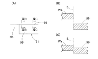
図10(A)にコーナー切込み92を拡大して示す。コーナー切込み92は、打抜刃部24の切込刃部25の打抜エッジ27で形成された箇所92aと切込エッジ30で形成された箇所92bとで様相が異なる。すなわち、打抜エッジ27で形成された箇所92aは、図10(B)に示すように、板材Wの本体部分Waに対しコーナー切込片93が完全に打抜かれて分離した状態となっているが、切込エッジ30で形成された箇所92bは、図10(C)に示すように、板材Wの本体部分Waに対しコーナー切込片93が完全に打抜かれておらず、両者Wa,93が段差を持って繋がった状態となっている。段差の大きさは、基端側へ行くほど小さく、基端では零になる。切込刃部25の底面28が先に説明した形状であるため、前記段差は、基端に近づくに従って、漸近線状に徐々に小さくなる。このように、板材Wの本体部分Waに対しコーナー切込片93を完全に分離させず、両者Wa,93の段差を徐々に小さくなるようにコーナー切込み92を形成したことにより、コーナー切込み92の基端付近で板材Wが加工硬化せず、切断面や切込面にダレがほとんど生じない。切込エッジ30で形成された箇所92bであっても、打抜エッジ27で形成された箇所92aに近い側では、板材Wの本体部分Waに対しコーナー切込片93が完全に打抜かれて分離している。
FIG. 10A shows an enlarged corner cut 92. The appearance of the corner cut 92 is different between a
追切り準備過程では、前記コーナー切断過程において形成されたコーナー切込片93に打抜刃部4が上下に重なり、かつ切込刃部5が打抜刃部4よりもコーナーから離れて位置するように配置した追切り切断用パンチ金型1と、この追切り切断用パンチ金型1に対応して配置した追切り切断用ダイ金型11とを用いてパンチ加工を行う。追切り切断用パンチ金型1の打ち下ろし高さは、図9(B)に示すように、同パンチ金型1の切込刃部5の底面9における凹部9aの打抜刃部4に対する反対側端の高さが、加工前の板材Wの上面の高さとなるようにする。それにより、打抜刃部4でコーナー切込片93の先端側を打抜いてパンチ孔94(図8(D))を開け、切込刃部5の切込エッジ10でコーナー切込み92に続いてコーナーから離れる側へ延びる追切り切込み95を形成し、その追切り切込み95の内側部分を切込刃部5の底面9で下方に押し下げて舌片状の追切り切込片96とする。先に説明したように、前記コーナー切断過程において形成されたコーナー切込み92の基端付近で加工硬化が起きていないため、追切り準備過程で追切り切断用パンチ金型1を用いて追切りを行ったとき、コーナー切断用パンチ金型31によるコーナー切込み92と追切り切断用パンチ金型1による追切り切込み95との継ぎ目部分にも両側箇所と同じ一様なダレが生じ、継ぎ目部分に痕跡がほとんど残らない。
In the follow-up preparation process, the
なお、追切り切断用パンチ金型1の切込刃部5の底面9が、凹部9aの打抜刃部4に対する反対側端に続いて同じ高さのまま延びた形状であると、板材Wの肉厚が誤差等により規定値よりも若干厚い場合に、上記同じ高さのまま延びた部分が板材Wを押圧して変形させてしまう。しかし、この実施形態のように、凹部9aの打抜刃部4に対する反対側端に続く部分が斜面部分9cとされていれば、上記事態を回避できる。また、凹部9aと斜面部分9cとは曲面部分9eを介して滑らかに繋がっているため、追切り切断用パンチ金型1の切込刃部5によって板材Wに生じる応力が、板材Wの面に沿って連続的に変化した状態にできる。すなわち、応力の加わる範囲とそうでない範囲との境界点を集中して発生させない。それにより、板材Wが定められた形状以外に変形することを防げる。
In addition, if the
図11(A)に追切り切込み95を拡大して示す。追切り切込み95は、切込刃部5の切込エッジ10における打抜刃部4に近い側で形成された箇所95aと遠い側で形成された箇所95bとでは様相が異なる。すなわち、打抜刃部4に近い側で形成された箇所95aは、図11(B)に示すように、板材Wの本体部分Waに対し追切り切込片96が完全に打抜かれて分離した状態となっているが、打抜刃部4から遠い側で形成された箇所95bは、図11(C)に示すように、板材Wの本体部分Waに対し追切り切込片96が完全に打抜かれておらず、両者Wa,96が段差を持って繋がった状態となっている。段差の大きさは、基端側ほど小さく、基端では零になる。切込刃部5の底面9が先に説明した形状であるため、前記段差は、基端に近づくに従って、漸近線状に徐々に小さくなる。このように、板材Wの本体部分Waに対し追切り切込片96を完全に分離させず、両者Wa,96の段差を徐々に小さくなるように追切り切込み95を形成したことにより、追切り切込み95の基端付近で板材Wが加工硬化せず、切断面や切込み面にダレがほとんど生じない。
FIG. 11A shows the
追切り準備過程に続いて、目標とする開口90の内縁である切断線に沿って位置をずらせながら追切り過程を複数回繰り返し行う。追切り過程は、追切り切断用パンチ金型1を、打抜刃部4が追切り準備過程または前回の追切り過程において形成された追切り切込片96に上下に重なり、かつ切込刃部5が打抜刃部4よりもコーナーから離れて位置するように配置して、パンチ加工を行うものである。この追切り過程の動作状態は、追切り準備過程の動作状態を示す図である図9(B)において、コーナー切込片93を追切り切込片96に置き換えたものに合致する。追切り切断用パンチ金型1の打ち下ろし高さは、同パンチ金型1の切込刃部5の底面9における凹部9aの打抜刃部4に対する反対側端の高さが、加工前の板材Wの上面の高さとなるようにする。
Following the follow-up preparation process, the follow-up process is repeated a plurality of times while shifting the position along the cutting line that is the inner edge of the
この追切り過程により、打抜刃部4で追切り切込片96の先端側部分を打抜いてパンチ孔94を開け、かつ切込刃部5の切込エッジ10で前回の追切り切込み95に続いてコーナーから離れる側へ延びる新たな追切り切込み95を形成し、その追切り切込み95の内側部分を切込刃部5の下面9で下方に押し下げて新たな追切り切込片96とする。先に説明したように、前記追切り準備過程または前回の追切り過程において形成された追切り切込み95の基端付近で加工硬化が起きていないため、追切り過程で追切り切断用パンチ金型1を用いて追切りを行ったとき、前回形成された追切り切込み95と今回形成された追切り切込み95との継ぎ目部分にも両側箇所と同じ一様なダレが生じ、継ぎ目部分に痕跡がほとんど残らない。
By this overcutting process, the
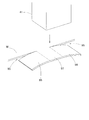
追切り過程が隣合う2つのコーナー間の中央部まで進んだなら、今度は反対側のコーナーから、上記コーナー切断過程、追切り準備過程、および追切り過程を逆向きに行う。図9(C)は追切り過程の状態を示す。そして、図12の斜視図に示すように、中央部に未切断の箇所97が残された状態とする。未切断の箇所97の両側は、両方向の最後に行われた追切り過程によってそれぞれ形成された一対の追切り切込片96になっている。残りの3辺についても同様に行う(図8(E))。なお、各パンチ金型1,21,41およびダイ金型11,31,51は角度割り出し可能なインデックスツールであるため、板材Wの向きを変えることなく、各辺について上記コーナー切断過程、追切り準備過程、および追切り過程を行える。
If the cut-off process has proceeded to the center between two adjacent corners, the corner cutting process, the cut-off preparation process, and the cut-off process are performed in reverse from the opposite corner. FIG. 9C shows the state of the follow-up process. Then, as shown in the perspective view of FIG. 12, an
最後に、打抜き過程により、図9(D)に示すように、上記未切断の箇所97および一対の追切り切込片96を打抜用パンチ金型41およびダイ金型51を用いて打抜く。最終の追切り過程において形成された追切り切込み95の基端付近で加工硬化が起きていないため、打抜用パンチ金型41で未切断の箇所97を打抜く場合も、追切り切込み95と打抜用パンチ金型41によるパンチ孔(図示せず)との継ぎ目部分にも両側箇所と同じ一様なダレが生じ、継ぎ目部分に痕跡がほとんど残らない。これにより、図8(F)に示すように、内周縁が滑らかな綺麗な開口90が形成される。
Finally, as shown in FIG. 9D, the
追切り切断用パンチ金型1の刃部3は、厚みが上から下まで一定であっても良いが、図13に示すように、下へ行くほどに厚みが増す形状としてもよい。図では厚みの変化を強調して表しているが、実際の厚みの変化はわずかである。
The
図示例の追切り切断用パンチ金型1は、切込刃部5の追切り方向に沿う両側面に切込エッジ10が形成されているが、例示した開口形成方法のように予め予備開口91を形成する場合は、切込刃部5の片方の側面にだけ切込エッジ10が形成されているものであってもよい。
The punching die 1 for the cut-off cutting in the illustrated example has the cutting edges 10 formed on both side surfaces along the cutting-off direction of the
また、図示例の追切り切断用パンチ金型1は、直線状の切断線に沿って追切り切断するためのものであり、打抜刃部4および切込刃部5の追切り方向に沿う側面が平面とされているが、図14に示す追切り切断用パンチ金型1´のように、打抜刃部4および切込刃部5の追切り方向に沿う側面を平面形状が円弧状の曲面とすれば、円弧状の切断線に沿って追切り切断することができる。
Further, the punching die 1 for additional cutting in the illustrated example is for performing additional cutting along a linear cutting line, and is along the additional cutting direction of the
1,1´…追切り切断用パンチ金型
4…打抜刃部
5…切込刃部
8…打抜エッジ
9…切込刃部の底面
9a…凹部
9b,9c…凹部の両側に続く部分
9d,9e…曲面部分
10…切込エッジ
21…コーナー切断用パンチ金型
24…打抜刃部
25…切込刃部
28…切込刃部の底面
28a…凹部
28b,28c…斜面部分
28d,28e…曲面部分
90…開口
92…コーナー切込み
93…コーナー切込片
94…パンチ孔
95…追切り切込み
96…追切り切込片
97…未切断の箇所
W…板材
DESCRIPTION OF
Claims (5)
追切り方向に並んで配置され、互いに側面が同一面上に位置してそれぞれの側面の下端縁が打抜エッジおよび切込エッジとされた打抜刃部および切込刃部を有し、
前記打抜刃部は、前記切込刃部よりも下方に段差を持って突出し、
前記切込刃部は、底面が前記打抜刃部から遠ざかるに従い上方に傾斜し、この底面における前記打抜刃部と前記切込刃部の並び方向の中間部が、上方に窪む側面形状の凹部とされ、この凹部の側面形状の輪郭線は、前記打抜刃部から遠ざかるに従って水平に対する傾斜角度が小さくなる形状である、
パンチプレスの追切り切断用パンチ金型。 It is a punch die for additional cut of a punch press for cutting along a continuous cutting line by performing additional cutting on a plate material,
Arranged side by side in the cut-off direction, each of which has a punching blade portion and a cutting blade portion whose side surfaces are located on the same surface and whose lower end edge is a punching edge and a cutting edge,
The punching blade portion protrudes with a step below the cutting blade portion,
The cutting blade portion is inclined upward as the bottom surface moves away from the punching blade portion, and an intermediate portion in the arrangement direction of the punching blade portion and the cutting blade portion on the bottom surface is recessed upward. The contour line of the side surface shape of the recess is a shape in which the inclination angle with respect to the horizontal decreases as the distance from the punching blade portion increases.
Punch die for additional cut of punch press.
外側面の下端縁が前記コーナー形状に沿う打抜エッジとされた打抜刃部と、一側面の下端縁が前記打抜エッジの両端にそれぞれ続き平面形状で打抜エッジの延長方向へ延びる切込エッジとされた2つの切込刃部とを有し、
前記打抜刃部は、前記切込刃部よりも下方に突出し、
前記切込刃部は、底面が前記打抜刃部から遠ざかるに従い上方に傾斜し、この底面における前記打抜刃部と前記切込刃部の並び方向の中間部が、上方に窪む側面形状の凹部であり、この凹部の側面形状の輪郭線は、前記打抜刃部から遠ざかるに従って水平に対する傾斜角度が小さくなる形状である、
パンチプレスのコーナー切断用パンチ金型。 A punch die for cutting a corner of a punch press for cutting a plate material along a predetermined corner shape,
A punching blade portion whose lower edge on the outer surface is a punching edge that follows the corner shape, and a cutting edge that extends in the extending direction of the punching edge in a planar shape with the lower edge on one side continuing to both ends of the punching edge. Having two cutting blades which are made into a cutting edge,
The punching blade portion protrudes downward from the cutting blade portion,
The cutting blade portion is inclined upward as the bottom surface moves away from the punching blade portion, and an intermediate portion in the arrangement direction of the punching blade portion and the cutting blade portion on the bottom surface is recessed upward. The contour line of the side surface shape of this recess is a shape in which the inclination angle with respect to the horizontal decreases as the distance from the punching blade portion increases.
Punch die for corner cutting of punch press.
前記コーナー切断用パンチ金型は、
外側面の下端縁が定められたコーナー形状に沿う打抜エッジとされた打抜刃部と、一側面の下端縁が前記打抜エッジの両端にそれぞれ続き平面形状で打抜エッジの延長方向へ延びる切込エッジとされた2つの切込刃部とを有し、
前記打抜刃部は、前記切込刃部よりも下方に突出し、
前記切込刃部は、底面が前記打抜刃部から遠ざかるに従い上方に傾斜し、この底面における前記打抜刃部と前記切込刃部の並び方向の中間部が、上方に窪む側面形状の凹部であり、この凹部の側面形状の輪郭線は、前記打抜刃部から遠ざかるに従って水平に対する傾斜角度が小さくなる形状である、
パンチプレスの追切り切断用・コーナー切断用パンチ金型組。 A die set comprising the punch die for additional cutting of the punch press according to claim 1 and the corner punching die for corner cutting of the punch press,
The corner cutting punch mold is
A punching blade portion having a punching edge along a corner shape with a lower end edge of the outer side surface, and a lower end edge of one side surface extending to both ends of the punching edge in a planar shape in the extending direction of the punching edge Two cutting blades that are extended cutting edges,
The punching blade portion protrudes downward from the cutting blade portion,
The cutting blade portion is inclined upward as the bottom surface moves away from the punching blade portion, and an intermediate portion in the arrangement direction of the punching blade portion and the cutting blade portion on the bottom surface is recessed upward. The contour line of the side surface shape of this recess is a shape in which the inclination angle with respect to the horizontal decreases as the distance from the punching blade portion increases.
Punch mold assembly for punch cutting and corner cutting of punch presses.
前記コーナー切断過程は、板材に形成しようとする開口のコーナーとなる箇所に前記コーナー切断用パンチ金型を用いてパンチ加工を行い、同パンチ金型の打抜刃部および切込み刃部により板材にコーナー切込みを形成し、そのコーナー切込みの内側部分を下方に押し下げてコーナー切込片とする過程であり、
前記追切り準備過程は、前記コーナー切込片に前記追切り切断用パンチ金型の打抜刃部が上下に重なり、かつ同パンチ金型の切込刃部が打抜刃部よりもコーナーから離れて位置するように配置した前記追切り切断用パンチ金型を用いてパンチ加工を行い、同パンチ金型の打抜刃部により前記コーナー切込片を打抜き、かつ同パンチ金型の切込刃部により、前記コーナー切込みに続いてコーナーから離れる側へ延びる追切り切込みを形成し、その追切り切込みの内側部分を下方に押し下げて追切り切込片とする過程であり、
前記追切り過程は、前記追切り準備過程に続いて複数回繰り返し行われ、前記追切り準備過程または前回の追切り過程において形成された追切り切込み片に前記追切り切断用パンチ金型の打抜刃部が上下に重なり、かつ同パンチ金型の切込刃部が打抜刃部よりもコーナーから離れて位置するように配置した前記追切り切断用パンチ金型を用いてパンチ加工を行い、同パンチ金型の打抜刃部により前記追切り切込片を打抜き、かつ同パンチ金型の切込刃部により、前記追切り切込みに続いてコーナーから離れる側へ延びる新たな追切り切込みを形成し、その追切り切込みの内側部分を下方に押し下げて新たな追切り切込片とする過程であり、
前記打抜き過程は、隣合う2つのコーナーから両コーナー間の中央側に向かって前記コーナー切断過程、追切り準備過程、および追切り過程を順に行って、両方向の最後に行われた追切り過程によってそれぞれ形成された未切断の箇所を、前記追切り切断用パンチ金型およびコーナー切断用パンチ金型とは別の打抜用パンチ金型を用いて打抜く打抜き過程である、
板材の開口形成方法。 A method for forming an opening of a plate material by a punch press using the punch die for additional cutting according to claim 1 or 2, and the punch die for corner cutting according to claim 3. Including cutting preparation process, additional cutting process, and punching process,
In the corner cutting process, punching is performed using the punch die for corner cutting at a location that becomes a corner of an opening to be formed in the plate material, and the punching blade portion and the cutting blade portion of the punch die are used to form the plate material. It is a process of forming a corner cut and pushing down the inner part of the corner cut downward to make a corner cut piece,
In the additional cutting preparation process, the punching blade portion of the punching die for additional cutting is vertically overlapped with the corner cut piece, and the cutting blade portion of the punch die is cut from the corner more than the punching blade portion. Punching is performed using the punch die for additional cutting that is disposed so as to be located apart, and the corner cut piece is punched by the punching blade portion of the punch die, and the punch die is cut The blade portion is a process of forming a follow-up cut extending to the side away from the corner following the corner cut, and pressing down the inner part of the cut-off to make a cut-off cut piece,
The additional cutting process is repeated a plurality of times following the additional cutting preparation process, and the additional cutting punch die is applied to the additional cutting piece formed in the additional cutting preparation process or the previous additional cutting process. Punching is performed using the punch die for additional cutting, which is arranged so that the punching blades overlap each other and the cutting blade of the punch die is located farther from the corner than the punching blade. The punching blade portion of the punch die cuts out the additional cutting piece, and the cutting blade portion of the punch die cuts out a new additional cutting cut extending from the corner to the side away from the corner. Is formed, and the inner portion of the additional cut is pushed downward to form a new additional cut piece,
The punching process is performed by sequentially performing the corner cutting process, the additional cut preparation process, and the additional cut process from the two adjacent corners toward the center between the two corners, and the final cut process performed in both directions. It is a punching process in which the uncut portions formed respectively are punched using a punching die other than the punching die for additional cutting and the punching die for corner cutting.
A method for forming openings in plate materials.
Priority Applications (2)
| Application Number | Priority Date | Filing Date | Title |
|---|---|---|---|
| JP2010136796A JP2012000631A (en) | 2010-06-16 | 2010-06-16 | Ripping cutting punch mold of punch press, corner cutting punch mold and method of forming plate material opening |
| PCT/JP2011/060986 WO2011158582A1 (en) | 2010-06-16 | 2011-05-12 | Formation of plate material opening using punch press |
Applications Claiming Priority (1)
| Application Number | Priority Date | Filing Date | Title |
|---|---|---|---|
| JP2010136796A JP2012000631A (en) | 2010-06-16 | 2010-06-16 | Ripping cutting punch mold of punch press, corner cutting punch mold and method of forming plate material opening |
Publications (1)
| Publication Number | Publication Date |
|---|---|
| JP2012000631A true JP2012000631A (en) | 2012-01-05 |
Family
ID=45347991
Family Applications (1)
| Application Number | Title | Priority Date | Filing Date |
|---|---|---|---|
| JP2010136796A Pending JP2012000631A (en) | 2010-06-16 | 2010-06-16 | Ripping cutting punch mold of punch press, corner cutting punch mold and method of forming plate material opening |
Country Status (2)
| Country | Link |
|---|---|
| JP (1) | JP2012000631A (en) |
| WO (1) | WO2011158582A1 (en) |
Cited By (3)
| Publication number | Priority date | Publication date | Assignee | Title |
|---|---|---|---|---|
| JP2014094394A (en) * | 2012-11-09 | 2014-05-22 | Amada Co Ltd | Metal mold for outrunning processing and outrunning processing method |
| JP5924421B2 (en) * | 2012-12-20 | 2016-05-25 | トヨタ自動車株式会社 | Cutting method and cutting apparatus |
| CN106552857A (en) * | 2015-09-24 | 2017-04-05 | 震旦(中国)有限公司 | A kind of corner cut punching one-time-shaped mould |
Families Citing this family (8)
| Publication number | Priority date | Publication date | Assignee | Title |
|---|---|---|---|---|
| JP6043684B2 (en) * | 2012-10-24 | 2016-12-14 | 株式会社アマダホールディングス | Over-cutting method and over-cutting die |
| CN104096755A (en) * | 2014-05-26 | 2014-10-15 | 太仓兴锋脚轮有限公司 | Punch forming equipment for trundle driving plate |
| CN104096751A (en) * | 2014-05-26 | 2014-10-15 | 太仓兴锋脚轮有限公司 | Castor driving plate punching molding equipment |
| CN104096752A (en) * | 2014-05-26 | 2014-10-15 | 太仓兴锋脚轮有限公司 | Punch forming equipment for trundle driving plate |
| CN104511515A (en) * | 2014-12-15 | 2015-04-15 | 无锡微研有限公司 | Side-cutting sub-mould structure of air conditioner fin mould |
| EP3112042B1 (en) * | 2015-06-30 | 2019-05-01 | TRUMPF Werkzeugmaschinen GmbH + Co. KG | Punching tool and method |
| CN109773016A (en) * | 2019-03-14 | 2019-05-21 | 安徽开乐专用车辆股份有限公司 | A kind of waterproof edges beam body leghole punch die |
| CN113290141A (en) * | 2021-05-20 | 2021-08-24 | 中车石家庄车辆有限公司 | Integrated punching die |
Family Cites Families (3)
| Publication number | Priority date | Publication date | Assignee | Title |
|---|---|---|---|---|
| JPH06297053A (en) * | 1993-04-13 | 1994-10-25 | Murata Mach Ltd | Passing cutting method and die |
| JP3401908B2 (en) * | 1994-03-31 | 2003-04-28 | 村田機械株式会社 | Punching punching die and punching cutting method |
| DE50100423D1 (en) * | 2001-12-06 | 2003-08-28 | Trumpf Werkzeugmaschinen Gmbh | Method and machine for multi-stroke progressive slitting of plate-like workpieces, in particular sheets |
-
2010
- 2010-06-16 JP JP2010136796A patent/JP2012000631A/en active Pending
-
2011
- 2011-05-12 WO PCT/JP2011/060986 patent/WO2011158582A1/en active Application Filing
Cited By (3)
| Publication number | Priority date | Publication date | Assignee | Title |
|---|---|---|---|---|
| JP2014094394A (en) * | 2012-11-09 | 2014-05-22 | Amada Co Ltd | Metal mold for outrunning processing and outrunning processing method |
| JP5924421B2 (en) * | 2012-12-20 | 2016-05-25 | トヨタ自動車株式会社 | Cutting method and cutting apparatus |
| CN106552857A (en) * | 2015-09-24 | 2017-04-05 | 震旦(中国)有限公司 | A kind of corner cut punching one-time-shaped mould |
Also Published As
| Publication number | Publication date |
|---|---|
| WO2011158582A1 (en) | 2011-12-22 |
Similar Documents
| Publication | Publication Date | Title |
|---|---|---|
| JP2012000631A (en) | Ripping cutting punch mold of punch press, corner cutting punch mold and method of forming plate material opening | |
| JP5644865B2 (en) | Punch press punch mold, post-cutting mold, and plate hole forming method | |
| EP2540428B1 (en) | Nibbler assembly for punch press and method of forming elongated hole in sheet material | |
| JPH084850B2 (en) | Mold used for punching method by punch press | |
| JP2611128B2 (en) | Cutting die for follow-up cutting | |
| KR20000030860A (en) | Method of making case of strut bearing using boards | |
| US2787922A (en) | Method of making cutting dies | |
| RU2297296C1 (en) | Blanking die set | |
| JP2007253225A (en) | Bending die in punch press and working method using the bending die | |
| JPH11197968A (en) | Composite working machine and plate working method using the composite working machine | |
| CN1143547A (en) | Punching technique of slotting and cutting-off for side wall of rectangular tubing | |
| KR20080012956A (en) | Progressive die tool method and apparatus | |
| JP3401908B2 (en) | Punching punching die and punching cutting method | |
| KR20140038643A (en) | Wheel type mold of nct | |
| JP2003245729A (en) | Press forming method for cylindrical formed product with flange | |
| JP2002001456A (en) | Press forming apparatus | |
| RU2220018C2 (en) | Method of drawing and drawing die | |
| JP2003230920A (en) | Side cutting die for punch press and cutting method | |
| CN209902025U (en) | Blanking die | |
| JP2009022976A (en) | Nibbling method for punch press, and punch press | |
| CN208600540U (en) | The manufacture tool of auto parts | |
| CN108043951A (en) | A kind of electronics lock access shifting block progressive die | |
| JPS63130227A (en) | Ripping method for press and die for ripping used in its method | |
| CN205967026U (en) | Continuously punching mould | |
| JP2004154800A (en) | Press forming device |