JP2011524948A - Method for controlling the time scale of gas supply into a processing chamber - Google Patents
Method for controlling the time scale of gas supply into a processing chamber Download PDFInfo
- Publication number
- JP2011524948A JP2011524948A JP2011514723A JP2011514723A JP2011524948A JP 2011524948 A JP2011524948 A JP 2011524948A JP 2011514723 A JP2011514723 A JP 2011514723A JP 2011514723 A JP2011514723 A JP 2011514723A JP 2011524948 A JP2011524948 A JP 2011524948A
- Authority
- JP
- Japan
- Prior art keywords
- gas
- mfc
- gas species
- overshoot
- flow rate
- Prior art date
- Legal status (The legal status is an assumption and is not a legal conclusion. Google has not performed a legal analysis and makes no representation as to the accuracy of the status listed.)
- Pending
Links
Images

Classifications
-
- G—PHYSICS
- G05—CONTROLLING; REGULATING
- G05D—SYSTEMS FOR CONTROLLING OR REGULATING NON-ELECTRIC VARIABLES
- G05D7/00—Control of flow
- G05D7/06—Control of flow characterised by the use of electric means
- G05D7/0617—Control of flow characterised by the use of electric means specially adapted for fluid materials
- G05D7/0629—Control of flow characterised by the use of electric means specially adapted for fluid materials characterised by the type of regulator means
- G05D7/0635—Control of flow characterised by the use of electric means specially adapted for fluid materials characterised by the type of regulator means by action on throttling means
-
- Y—GENERAL TAGGING OF NEW TECHNOLOGICAL DEVELOPMENTS; GENERAL TAGGING OF CROSS-SECTIONAL TECHNOLOGIES SPANNING OVER SEVERAL SECTIONS OF THE IPC; TECHNICAL SUBJECTS COVERED BY FORMER USPC CROSS-REFERENCE ART COLLECTIONS [XRACs] AND DIGESTS
- Y10—TECHNICAL SUBJECTS COVERED BY FORMER USPC
- Y10T—TECHNICAL SUBJECTS COVERED BY FORMER US CLASSIFICATION
- Y10T137/00—Fluid handling
- Y10T137/7722—Line condition change responsive valves
- Y10T137/7758—Pilot or servo controlled
- Y10T137/7761—Electrically actuated valve
Abstract
【課題】
【解決手段】レシピに対してマスフローコントローラ(MFC)制御スキームを確立する方法が提供されており、MFC制御スキームは、処理チャンバ内へのガス供給のタイムスケールを短縮するよう構成される。その方法は、レシピの実行中に利用され、目標供給タイムスケールよりも遅い1組の供給時間を有する1組の遅延ガス種を特定する工程を備える。その方法は、さらに、1組の遅延ガス種に含まれる各ガス種の初期オーバーシュート強度および初期オーバーシュート持続時間を確立する工程を含む。方法は、さらに、レシピの実行中に各ガス種のMFCハードウェアを調整することによってMFC制御スキームを確立する工程を含む。MFCハードウェアの調整は、MFC制御スキームが、各ガス種に、処理チャンバの平衡圧の目標精度の範囲内にある圧力プロファイルを提供するか否かを判定するために、初期オーバーシュート強度を初期オーバーシュート持続時間にわたって適用することを含む。
【選択図】図2【Task】
A method is provided for establishing a mass flow controller (MFC) control scheme for a recipe, wherein the MFC control scheme is configured to reduce a time scale of gas supply into a processing chamber. The method comprises the step of identifying a set of delayed gas species that are utilized during execution of the recipe and that have a set of supply times that are slower than a target supply time scale. The method further includes establishing an initial overshoot strength and an initial overshoot duration for each gas species included in the set of delayed gas species. The method further includes establishing an MFC control scheme by adjusting the MFC hardware for each gas type during the execution of the recipe. Tuning the MFC hardware is done by initializing the initial overshoot intensity to determine whether the MFC control scheme provides each gas species with a pressure profile that is within the target accuracy of the process chamber equilibrium pressure. Including applying for overshoot duration.
[Selection] Figure 2
Description
プラズマ処理の進歩は、半導体業界の成長を促進した。競争の激しい半導体業界において、製造業者は、スループットを最大化すること、および/または、品質の高いデバイスを製造することができれば、競争力を高めることができる。スループットを制御するための一方法は、処理チャンバ内へのガスの流入を制御することである。 Advances in plasma processing have promoted the growth of the semiconductor industry. In the highly competitive semiconductor industry, manufacturers can be more competitive if they can maximize throughput and / or manufacture high quality devices. One way to control the throughput is to control the gas flow into the processing chamber.
通例、基板処理のために、レシピは、2以上のガス種を必要としうる。理想的には、それらのガス種は、混合されて、同時に処理チャンバ内で平衡圧状態(例えば、設定圧力)に達する。しかし、いくつかの因子によって、ガス種は異なるタイムスケール(時間尺度、すなわち、供給時間)を有することがある。 Typically, for substrate processing, a recipe may require more than one gas species. Ideally, the gas species are mixed and at the same time reach an equilibrium pressure condition (eg, set pressure) within the processing chamber. However, depending on several factors, gas species may have different time scales (time scales, i.e. feed times).
ガス供給時間に影響しうる1つの因子は、ガス種の質量である。より重い分子量のガス種が、より軽い分子量のガス種よりもゆっくりと進みうることは、当業者にとって周知である。ガス種の間の質量差は、低圧環境で各ガス種の流量に影響しうる。低圧環境では、ガス流は分子になる場合があり、各ガス種は、実質的には互いに独立したものになりうる。結果として、複数のガス種の分離が起こって、チャンバでのガス組成の変動(drift)につながる。換言すれば、ガス種は、異なる時間に平衡状態に達しうる。したがって、各ガスに対するタイムスケール(例えば、供給時間)が異なりうる。 One factor that can affect the gas supply time is the mass of the gas species. It is well known to those skilled in the art that heavier molecular weight gas species can proceed more slowly than lighter molecular weight gas species. The mass difference between the gas species can affect the flow rate of each gas species in a low pressure environment. In a low pressure environment, the gas flow can be molecular, and each gas species can be substantially independent of each other. As a result, separation of multiple gas species occurs, leading to drift of gas composition in the chamber. In other words, the gas species can reach equilibrium at different times. Thus, the time scale (eg, supply time) for each gas can be different.
ガス供給タイムスケールに影響しうる別の因子は、ガスラインの形状である。前述したように、レシピは、基板処理を実行するために、2以上のガス種を必要としうる。各ガスは、ガスラインから混合マニホルド(メインガスライン)に流れ込んでよい。各ガスラインの形状は、ガスの流れに影響しうる。一例として、ガスが流れるガスラインが長いほど、供給時間は長くなる。 Another factor that can affect the gas supply time scale is the shape of the gas line. As described above, a recipe may require more than one gas species to perform substrate processing. Each gas may flow from a gas line into a mixing manifold (main gas line). The shape of each gas line can affect the gas flow. As an example, the longer the gas line through which the gas flows, the longer the supply time.
いくつかのレシピは、低流量ガスを高流量ガスと混合させてよい。このタイプのガス供給は、キャリアガスによる供給として知られており、高流量ガス(キャリアガス)が、分子衝突によって低流量ガス(プロセスガス)の流れを推進する。キャリアガスが流れている混合マニホルド内にプロセスガスが入るためには、プロセスガスは、混合マニホルドの圧力と同程度に圧力を上昇させる必要がある。しかし、キャリアガスがプロセスガスよりもずっと高い流量で流れている場合、プロセスガスが、十分に圧力を高めてキャリアガスと混合するには、非常に長い時間がかかる場合がある。この場合、キャリアガスは、プロセスガスを搬送することなく処理チャンバに到達する。したがって、キャリアは、プロセスガスよりも前に平衡状態に到達する結果、ガス組成の変動を引き起こす。 Some recipes may mix a low flow gas with a high flow gas. This type of gas supply is known as carrier gas supply, where a high flow gas (carrier gas) drives the flow of a low flow gas (process gas) by molecular collision. In order for the process gas to enter the mixing manifold in which the carrier gas is flowing, the process gas needs to increase in pressure to the same extent as the pressure in the mixing manifold. However, if the carrier gas is flowing at a much higher flow rate than the process gas, it may take a very long time for the process gas to sufficiently increase pressure and mix with the carrier gas. In this case, the carrier gas reaches the processing chamber without conveying the process gas. Thus, the carriers reach an equilibrium state before the process gas, resulting in gas composition fluctuations.
以上からわかるように、望ましくない結果が、ガス組成変動によって生じうる。ほとんどのレシピでは、ガス組成変動にかかわらず、処理チャンバ内の圧力が安定した時に、基板処理が開始されうる。適切なガス混合物なしに基板処理を実行することにより、不良デバイスが製造される場合がある。他のレシピとして、処理チャンバ内の各ガス種が、処理の開始前に必要な平衡状態に到達することを求める場合もある。しかし、さらなる時間が必要とされる結果、処理時間が長くなり、基板の処理量が少なくなりうる。 As can be seen, undesirable results can occur due to gas composition fluctuations. In most recipes, substrate processing can begin when the pressure in the processing chamber is stable, regardless of gas composition variations. By performing substrate processing without an appropriate gas mixture, defective devices may be manufactured. As another recipe, each gas species in the processing chamber may be required to reach the required equilibrium before starting the process. However, as a result of the additional time required, the processing time becomes longer and the processing amount of the substrate can be reduced.
本発明は、一実施形態において、レシピに対してマスフローコントローラ(MFC)制御スキームを確立する方法に関し、MFC制御スキームは、プラズマ処理システムの処理チャンバ内へのガス供給のタイムスケールを短くするよう構成される。その方法は、レシピの実行中に利用され、目標供給タイムスケールよりも遅い1組の供給時間を有する1組の遅延ガス種を特定する工程を備える。方法は、さらに、1組の遅延ガス種に含まれる各ガス種の初期オーバーシュート強度を確立する工程を備えており、初期オーバーシュート強度は、MFC流量を増大させる因子である。その方法は、さらに、1組の遅延ガス種に含まれる各ガス種の初期オーバーシュート持続時間を決定する工程を含む。初期オーバーシュート持続時間は、初期オーバーシュート強度をMFC流量に適用するための持続時間である。方法は、さらに、1組の遅延ガス種に含まれる各ガス種のMFCハードウェアを調整してレシピを実行することによってMFC制御スキームを検証する工程を備えており、MFCハードウェアを調整することは、MFC制御スキームが、1組の遅延ガス種に含まれる各ガス種に、処理チャンバの平衡圧の目標精度の範囲内にある圧力プロファイルを提供するか否かを判定するために、初期オーバーシュート強度を初期オーバーシュート持続時間にわたって適用することを含む。 The present invention, in one embodiment, relates to a method for establishing a mass flow controller (MFC) control scheme for a recipe, wherein the MFC control scheme is configured to reduce the time scale of gas supply into a processing chamber of a plasma processing system. Is done. The method comprises the step of identifying a set of delayed gas species that are utilized during execution of the recipe and that have a set of supply times that are slower than a target supply time scale. The method further comprises establishing an initial overshoot strength for each gas species included in the set of delayed gas species, the initial overshoot strength being a factor that increases the MFC flow rate. The method further includes determining an initial overshoot duration for each gas species included in the set of delayed gas species. The initial overshoot duration is the duration for applying the initial overshoot intensity to the MFC flow rate. The method further comprises the step of verifying the MFC control scheme by adjusting the MFC hardware of each gas type included in the set of delayed gas types and executing the recipe, and adjusting the MFC hardware Is used to determine whether the MFC control scheme provides each gas species in a set of retarded gas species with a pressure profile that is within the target accuracy of the equilibrium pressure of the processing chamber. Applying shoot intensity over an initial overshoot duration.
上述の発明の概要は、本明細書に開示された本発明の多くの実施形態の内の1つのみに関するものであり、特許請求の範囲に記載される本発明の範囲を限定する意図はない。添付の図面を参照しつつ行う本発明の詳細な説明において、本発明の上述の特徴およびその他の特徴を詳述する。 The above summary of the present invention is only relevant to one of the many embodiments of the present invention disclosed herein and is not intended to limit the scope of the present invention as recited in the claims. . The foregoing and other features of the invention are described in detail in the detailed description of the invention with reference to the accompanying drawings.
添付の図面では、限定ではなく例示を目的として本発明を図示する。なお、これらの添付図面においては、同様の構成要素には同様の符号が付されている。 The accompanying drawings illustrate the invention for purposes of illustration and not limitation. In the accompanying drawings, the same reference numerals are assigned to the same components.
以下では、添付図面に例示されたいくつかの実施形態を参照しつつ、本発明の詳細な説明を行う。以下の説明では、本発明の完全な理解を促すために、数多くの具体的な詳細事項が示されている。しかしながら、当業者にとって明らかなように、本発明は、これらの具体的な詳細事項の一部または全てがなくとも実施することが可能である。また、本発明が不必要に不明瞭となるのを避けるため、周知の処理工程および/または構造については、詳細な説明を省略した。 The present invention will be described in detail below with reference to some embodiments illustrated in the accompanying drawings. In the following description, numerous specific details are set forth in order to provide a thorough understanding of the present invention. However, it will be apparent to those skilled in the art that the present invention may be practiced without some or all of these specific details. In other instances, well known process steps and / or structures have not been described in detail in order to avoid unnecessarily obscuring the present invention.
以下では、方法および技術を含め、様々な実施形態について説明する。本発明は、本発明の技術の実施形態を実行するためのコンピュータ読み取り可能な命令を格納するコンピュータ読み取り可能な媒体を含む製品も含みうることに留意されたい。コンピュータ読み取り可能な媒体としては、例えば、コンピュータ読み取り可能な暗号を格納するための半導体、磁気、光磁気、光学、または、その他の形態のコンピュータ読み取り可能な媒体が挙げられる。さらに、本発明は、本発明の実施形態を実施するための装置も含んでよい。かかる装置は、本発明の実施形態に関するタスクを実行するために、専用および/またはプログラム可能な回路を備えてよい。かかる装置の例は、汎用コンピュータおよび/または適切にプログラムされた専用コンピュータデバイスを含み、本発明の実施形態に関する様々なタスクに適合したコンピュータ/コンピュータデバイスおよび専用/プログラム可能回路を組み合わせたものを含んでもよい。 In the following, various embodiments will be described, including methods and techniques. It should be noted that the present invention may also include products including computer readable media storing computer readable instructions for performing embodiments of the technology of the present invention. Computer-readable media include, for example, semiconductor, magnetic, magneto-optical, optical, or other forms of computer-readable media for storing computer-readable encryption. Furthermore, the present invention may also include an apparatus for carrying out an embodiment of the present invention. Such an apparatus may comprise dedicated and / or programmable circuitry to perform the tasks associated with embodiments of the present invention. Examples of such devices include general purpose computers and / or appropriately programmed dedicated computer devices, including combinations of computer / computer devices and dedicated / programmable circuits adapted to various tasks relating to embodiments of the present invention. But you can.
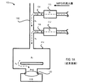
上述したように、従来技術では、処理チャンバが平衡圧状態(すなわち、設定圧力点)に到達した後に1または複数のガス種が処理チャンバ内に流れ込む場合に、供給遅延が起こりうる。異なるガス種が異なる時間にチャンバに到達しうるため、ガス組成変動が起こりうる。説明を容易にするために、図1Aは、ガス供給システムの部分概略図を示す。 As described above, in the prior art, a supply delay can occur when one or more gas species flow into the processing chamber after the processing chamber reaches an equilibrium pressure state (ie, a set pressure point). Gas composition variations can occur because different gas species can reach the chamber at different times. For ease of explanation, FIG. 1A shows a partial schematic diagram of a gas supply system.
処理ツール100は、処理チャンバ114内にガスを供給するガス供給システムを備えてよい。ガス供給システムは、メインガスライン102(すなわち、混合マニホルド)と、1または複数のガスライン(104および106)とを備えてよい。各ガスラインを通るガスの流れは、MFC110およびMFC112などのマスフローコントローラ(MFC)によって制御されてよい。
The
通例、処理チャンバ114に流入するガス流は、高圧のガス混合物および低圧の処理チャンバ114の圧力差によって推進される。処理チャンバ114の圧力は、センサによって監視される。センサの測定値に基づいて、真空ポンプ118は、真空ポンプ流入口に位置するスロットルバルブ130を調節してよい。スロットルバルブ130を調節することによって、真空ポンプ118は、処理チャンバ114内の圧力を制御してよい。スロットルバルブ130の開度は、処理チャンバ114から真空ポンプ118までのガスコンダクタンス(体積ガス流量)を制御し、それによって、処理チャンバ114内の圧力を、指定の平衡圧に維持する。以下の式1は、平衡状態において、チャンバの所与のガス種の分圧(p2)が、MFCによって制御されたガス流(Q)と、ポンプに対するチャンバのコンダクタンス(k2)と、の比に等しい平衡圧(pe)に到達することを示している。
Typically, the gas stream entering the

実際には、スロットルバルブ130の初期のバルブ開度を設定するために、所与の流量および圧力の各ガスについて、ガスコンダクタンス曲線が経験的に決定されてよい。処理チャンバ114内の圧力が設定圧力点に到達すると、基板処理が開始されてよい。
In practice, a gas conductance curve may be empirically determined for each gas at a given flow rate and pressure to set the initial valve opening of the
しかし、チャンバ圧力が安定したとしても、処理環境が、基板処理に理想的なものではない場合がある。理想的には、異なるガス種は、処理チャンバ114に到達する前に混合される。しかし、処理チャンバ114に供給された混合ガスが、必要なガス種を正確な比率で含んでいない場合がある。換言すると、ガス組成が、処理チャンバ114内で変動する場合がある。上記の式2は、特定の時刻(t)での分圧(p2)が、ガスラインを通るガス流タイムスケール(τ1)、処理チャンバからポンプへのガス流タイムスケール(τ2)、MFCガス流量(Q)、および、チャンバとポンプとの間のコンダクタンス(k2)に依存することを示す。
However, even if the chamber pressure is stable, the processing environment may not be ideal for substrate processing. Ideally, different gas species are mixed before reaching the
典型的な処理環境において、タイムスケール(τ2)および流量コンダクタンス(k2)は、両方が処理チャンバの形状およびポンプ速度の関数であるため、通常は変化がない。したがって、時刻tにおける分圧(p2)は、ガスラインのタイムスケール(τ1)および所与のガスのMFC流量(Q)に主に依存する。 In a typical processing environment, the time scale (τ 2 ) and flow conductance (k 2 ) are usually unchanged because both are functions of the processing chamber geometry and pump speed. Thus, the partial pressure (p 2 ) at time t depends mainly on the gas line time scale (τ 1 ) and the MFC flow rate (Q) for a given gas.
ガスラインのタイムスケール(τ1)は、ガスラインの形状によって決定され、式3に示すように、ガス種の質量の平方根に反比例する。簡単のために、ガスの質量は因子でないと仮定する。一例において、ガスライン104およびガスライン106を流れるガスは、同じガスである。ガスの質量が因子でない場合、ガスラインのタイムスケール(τ1)は、上記の式4に示すように、ガスラインの形状の因子である。
The gas line time scale (τ 1 ) is determined by the shape of the gas line and is inversely proportional to the square root of the mass of the gas species, as shown in Equation 3. For simplicity, assume that the mass of the gas is not a factor. In one example, the gas flowing through the
上記の式4によると、ガスラインのタイムスケール(τ1)は、ガスラインの体積(V1)およびガスラインのコンダクタンス(k1)の関数である。ガスラインの体積および流量コンダクタンスは両方とも、ガスラインの長さおよび/または直径の関数であるため、ガスラインのタイムスケール(τ1)は、ガスラインの長さおよび/または直径の関数でもある。一例において、ガスライン106はガスライン104よりも短い長さを有すると仮定する。上記の式4に基づくと、ガスライン104の体積はガスライン106の体積よりも大きく、ガスライン104の流量コンダクタンスはガスライン106よりも小さい。したがって、ガスライン104のガス供給タイムスケールは、ガスライン106のガス供給タイムスケールよりも大きい。
According to Equation 4 above, the gas line time scale (τ 1 ) is a function of the gas line volume (V 1 ) and the gas line conductance (k 1 ). Since the gas line volume and flow conductance are both a function of the length and / or diameter of the gas line, the gas line time scale (τ 1 ) is also a function of the length and / or diameter of the gas line. . In one example, assume that
式3に戻ると、ガスラインの形状に加えて、ガスラインのタイムスケール(τ1)は、ガスの分子量の関数でもある。生産環境において、レシピによって必要とされるガス種は、通常、異なる分子量を有しうる。ガスの質量は、低圧環境で特に重要である。低圧環境では、ガス流は分子になりうる。換言すると、ガス流は互いに独立しうる(すなわち、衝突の運動量移行がガス分子間で最小になりうる)。いくつかの異なるガス種を有するレシピについて、ガスの質量は、ガスの供給時間を決定しうる。同じ物理的条件(各ガスラインが同じガスライン形状を有する、各ガス種が同じ質量流量で流れている、など)を仮定すると、重いガス種は、軽いガス種よりも遅い速度で流れる。一例として、H2の供給時間は、C4F8よりも約3倍速くなる。結果として、軽いガス種は、重いガス種の前に処理チャンバ内で平衡圧に達しうる。換言すると、ガス種は、分離して、各ガスは、異なる時間に平衡状態に達しうる。 Returning to Equation 3, in addition to the shape of the gas line, the time scale (τ 1 ) of the gas line is also a function of the molecular weight of the gas. In a production environment, the gas species required by the recipe usually can have different molecular weights. The mass of the gas is particularly important in low pressure environments. In low pressure environments, the gas stream can be molecular. In other words, the gas flows can be independent of each other (ie, collisional momentum transfer can be minimized between gas molecules). For recipes with several different gas species, the mass of the gas can determine the gas delivery time. Assuming the same physical conditions (each gas line has the same gas line shape, each gas species is flowing at the same mass flow rate, etc.), heavy gas species flow at a slower rate than light gas species. As an example, the supply time of H 2 is about 3 times faster than C 4 F 8 . As a result, light gas species can reach an equilibrium pressure in the processing chamber before heavy gas species. In other words, the gas species are separated and each gas can reach equilibrium at different times.
したがって、処理チャンバ114内の圧力安定化は、正確なガス混合物が処理チャンバ内に供給されていなくても到達されうる。一部のレシピについては、適切なガス混合物が存在しえない場合でも基板処理が始まりうるため、それにより、不良デバイスが製造される結果となる。他のレシピについては、適切なガス混合物が存在するまで基板処理が遅延されうるが、遅延時間によって処理時間が長くなるために製造コストが増大しうる。
Thus, pressure stabilization within the
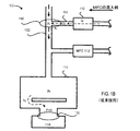
処理環境が低圧環境ではなくても、プロセスガスの圧力がキャリアガスの圧力よりもかなり小さい場合には、ガス供給が遅延されうる。図1Bは、キャリアガスによる流動環境におけるガスの流れを示した簡単なブロック図である。この例では、アルゴンなどのキャリアガスが、プロセスガスよりもはるかに大きい流量でメインガス供給ライン102(例えば、混合マニホルド)内に注入されてよい。キャリアガスによる流動環境において、プロセスガスは、通常、衝突運動量移送を通じてキャリアガスによって処理チャンバ114内に搬送される。しかし、交差部分150(ガスラインが混合マニホルドと交わる部分)のキャリアガス圧力(pc)がプロセスガス圧力(p1)よりも高いと、プロセスガスはキャリアガスと混合することができない場合がある。結果として、プロセスガスは、プロセスガス圧力(p1)がキャリアガス圧力(pc)に到達するまで、交差部分150で「滞留」する。
Even if the processing environment is not a low pressure environment, the gas supply can be delayed if the pressure of the process gas is much less than the pressure of the carrier gas. FIG. 1B is a simple block diagram illustrating a gas flow in a flowing environment using a carrier gas. In this example, a carrier gas such as argon may be injected into the main gas supply line 102 (eg, a mixing manifold) at a much higher flow rate than the process gas. In a flowing environment with a carrier gas, the process gas is typically transported into the
換言すると、ガスライン(例えば、ガスライン104)内のプロセスガスが、メインガスライン102を流れるキャリアガスと混合しうる前に、ガスライン104内で十分な圧力上昇がなされる必要がありうる。一部の例では、プロセスガスがMFC110からガスライン104に放出された時間から、プロセスガスがキャリアガスと混合することを可能にするために十分な圧力上昇がなされるまでの間に、非常に長い遅延が生じうる。以下の式5は、交差部分150での圧力上昇に必要なタイムスケールを示す。図5に示すように、遅延時間は、ガスラインの体積が大きいほど、そして、流量(Q)が小さいほど、長くなる。
In other words, a sufficient pressure increase in the
図1Aおよび図1Bで説明したように、低圧チャンバ環境に流入するプロセスガスの遅延により、設定圧力点よりも後にプロセスガス流の安定化に到達することになる。換言すると、特定のガス種のガス供給タイムスケールが、ガス組成変動を引き起こしうる。遅延を最小化するため、および/または、処理チャンバ内の平衡圧を制御するために、少なくとも1つのパラメータ(ガスラインのコンダクタンス、MFC流量、または、ポンプ速度)を修正しなければならない場合がある。本発明の一態様において、発明者は、短期間でMFC流量を増大させることによって、ハードウェアの変更を必要とすることなく、ガス供給タイムスケールを制御できることを認識した。 As described in FIGS. 1A and 1B, the process gas flow entering the low pressure chamber environment will reach stabilization of the process gas flow after the set pressure point. In other words, the gas supply time scale of a particular gas type can cause gas composition fluctuations. At least one parameter (gas line conductance, MFC flow rate, or pump speed) may need to be modified to minimize delays and / or to control the equilibrium pressure in the processing chamber. . In one aspect of the present invention, the inventors have recognized that increasing the MFC flow rate in a short period of time can control the gas supply time scale without requiring hardware changes.
本発明の実施形態によると、処理チャンバへのガス供給のタイムスケールを短縮するためのマスフロー制御(MFC)スキームが提供される。本発明の実施形態は、実効ガス供給タイムスケールを短縮するために、MFCをオーバーシュートさせることを含む。本発明の実施形態は、さらに、キャリアガスによる流動環境の間に供給時間を短縮するためにオーバーシュートを実行するための複数工程の処理を含む。 According to embodiments of the present invention, a mass flow control (MFC) scheme is provided for reducing the time scale of gas supply to a processing chamber. Embodiments of the present invention include overshooting the MFC to reduce the effective gas supply time scale. Embodiments of the present invention further include a multi-step process for performing overshoot to reduce the supply time during the flow environment with the carrier gas.
本発明の一実施形態では、1つのガスについて処理チャンバへの供給遅延を短縮するためにMFCをオーバーシュートさせる単一工程のオーバーシュート方法が提供されている。供給遅延を最小化するために、最適オーバーシュート強度が決定されてよい。最適オーバーシュート強度は、処理チャンバ内のガス組成変動を確実に最小化するためにMFC流量を増大させうる因子である。供給遅延の短縮は基板処理の質を向上させるため、最適なオーバーシュート強度とすることが望ましい。最適なオーバーシュート強度を決定するために、初期オーバーシュート強度が算出されてよい。初期オーバーシュート強度は、オーバーシュート持続時間と、遅延したガス種のタイムスケール(τ1)との関数である。本明細書に記載のように、オーバーシュート持続時間とは、オーバーシュート強度がMFC流量に適用されうる経過時間を指す。 In one embodiment of the present invention, a single-step overshoot method is provided for overshooting the MFC to reduce the supply delay to the processing chamber for one gas. In order to minimize the supply delay, an optimal overshoot strength may be determined. Optimal overshoot strength is a factor that can increase the MFC flow rate to reliably minimize gas composition fluctuations in the processing chamber. Since shortening the supply delay improves the quality of substrate processing, it is desirable to set the optimum overshoot strength. An initial overshoot strength may be calculated to determine the optimal overshoot strength. The initial overshoot intensity is a function of the overshoot duration and the time scale (τ 1 ) of the delayed gas species. As described herein, overshoot duration refers to the elapsed time overshoot intensity can be applied to the MFC flow rate.
一実施形態において、オーバーシュート持続期間は、MFCの応答時間に設定される(例えば、MFCが一連の命令に応答できる速度)。典型的なMFCについては、MFC設定が変更された時に、応答遅延が存在しうる。換言すると、MFC設定が変更されると、ガス流量が変更されるまでに、数秒が経過しうる。一例において、MFCが2秒間の応答遅延を有すると仮定する。ツールのオペレータが、最初にMFCを20sccmに設定し、その後すぐにMFC設定を10sccmに変更した場合、MFCは、10sccmでガスを放出する前に2秒間20sccmでガスを放出しうる。遅延は、MFC応答時間によるものであり、ツールオペレータの故意によるものではない。その意図は、処理チャンバへのガス供給のタイムスケールを最小化することであるため、MFC応答時間に設定されたオーバーシュート持続時間は、供給時間全体に、ほとんどまたは全く時間を追加することがなく、それにより、ガス供給のタイムスケールを制御するための方法としてオーバーシュート強度を利用することを可能にしつつ、オーバーシュート持続時間を適用する必要がある時間を最小化することができる。 In one embodiment, the overshoot duration is set to the response time of the MFC (eg, the rate at which the MFC can respond to a series of commands). For a typical MFC, there may be a response delay when the MFC settings are changed. In other words, when the MFC setting is changed, several seconds may elapse before the gas flow rate is changed. In one example, assume that the MFC has a response delay of 2 seconds. If the tool operator first sets the MFC to 20 sccm and then immediately changes the MFC setting to 10 sccm, the MFC may release gas at 20 sccm for 2 seconds before releasing gas at 10 sccm. The delay is due to the MFC response time and not the intention of the tool operator. Since its intent is to minimize the time scale of gas supply to the processing chamber, the overshoot duration set for the MFC response time adds little or no time to the overall supply time. Thereby, the time required to apply the overshoot duration can be minimized while allowing the overshoot intensity to be utilized as a method for controlling the time scale of the gas supply.
以上からわかるように、応答時間は、MFCに固有のものであってよい。換言すると、第1のMFCが第2のMFCと異なる応答時間を有する場合、第1のMFCに関連する第1のガス種の初期オーバーシュート強度は、第2のMFCに関連する第2のガス種の初期オーバーシュート強度と異なっていてよい。したがって、オーバーシュート持続時間は、MFC応答時間によって制限される。 As can be seen from the above, the response time may be unique to the MFC. In other words, if the first MFC has a different response time than the second MFC, the initial overshoot intensity of the first gas species associated with the first MFC is the second gas associated with the second MFC. It may be different from the seed's initial overshoot intensity. Therefore, the overshoot duration is limited by the MFC response time.
前述したように、オーバーシュート強度は、遅延したガス種のタイムスケール(τ1)の関数でもある。タイムスケールτ1は、ガスラインの形状およびガスの分子量によって決まるため、より長いガスラインに対応するには、オーバーシュート強度を増大させなければならない場合がある。同様に、重い分子量のガスに対しても、オーバーシュート強度を増大させなければならない場合がある。 As described above, the overshoot intensity is also a function of the time scale (τ 1 ) of the delayed gas species. Since the time scale τ 1 is determined by the shape of the gas line and the molecular weight of the gas, the overshoot strength may need to be increased to accommodate longer gas lines. Similarly, overshoot strength may have to be increased for heavy molecular weight gases.
初期オーバーシュート強度が決定されると、初期オーバーシュート強度の因子によって増大されたMFC流量で、試験運転が実行されてよい。一例では、設定MFC流量が20sccmであり、初期オーバーシュート強度が1.5である場合、MFCは、最初に30sccmに設定される。試験中、チャンバ圧力プロファイルは、所定の期間(例えば、10秒間)観察されてよい。チャンバ圧力プロファイルを分析することによって、初期オーバーシュート強度は、最適オーバーシュート強度を特定するために調整されてよい。一実施形態において、所定の目標期間(例えば2秒間)のチャンバ圧が目標精度(例えば、設定圧力点の1パーセント)以内になるチャンバ圧力プロファイルをオーバーシュート強度が生成するまで、初期オーバーシュート強度を調整することによって、オーバーシュート強度は決定されてよい。通常は、安定化した圧力環境を確立するために提供される時間が限られているため、所定の目標期間は、処理チャンバ圧力を安定化させるために割り当てられた時間よりも短い期間に設定されなければならない場合がある。 Once the initial overshoot strength is determined, a test run may be performed with the MFC flow rate increased by a factor of the initial overshoot strength. In one example, if the set MFC flow rate is 20 sccm and the initial overshoot strength is 1.5, the MFC is initially set to 30 sccm. During the test, the chamber pressure profile may be observed for a predetermined period of time (eg, 10 seconds). By analyzing the chamber pressure profile, the initial overshoot intensity may be adjusted to identify the optimal overshoot intensity. In one embodiment, the initial overshoot intensity is increased until the overshoot intensity produces a chamber pressure profile that results in a chamber pressure for a predetermined target period (eg, 2 seconds) within a target accuracy (eg, 1 percent of the set pressure point) By adjusting, the overshoot intensity may be determined. Typically, because the time provided to establish a stabilized pressure environment is limited, the predetermined target period is set to a period shorter than the time allotted to stabilize the process chamber pressure. You may have to.
代替的または追加的に、初期オーバーシュート強度がMFCの能力の範囲内にない場合に、オーバーシュート持続時間が調整されてもよい。前述したように、オーバーシュート持続時間は、オーバーシュートによって追加される時間を最小化するために、MFCの応答時間に設定されてよい。ただし、修正されたMFC流量(すなわち、オーバーシュート強度の因子によって増大された質量流量)が、MFCの最大流量に近すぎる場合、オーバーシュート強度を低減するために、オーバーシュート持続時間を長くしてもよい。換言すると、オーバーシュート持続時間は、修正された質量流量が最大MFC流量の所定の割合(95%など)以上である場合に修正されてよい。一実施形態において、所定の割合は、MFCに存在しうる潜在的なハードウェア誤差を考慮して、100%未満である。各MFCは異なる仕様を有しうるため、最大MFC流量は、MFCによって変わりうる。 Alternatively or additionally, the overshoot duration may be adjusted when the initial overshoot strength is not within the capability of the MFC. As described above, the overshoot duration may be set to the response time of the MFC to minimize the time added by overshoot. However, if the modified MFC flow rate (ie, the mass flow rate increased by the overshoot strength factor) is too close to the maximum flow rate of the MFC, the overshoot duration can be increased to reduce the overshoot strength. Also good. In other words, the overshoot duration may be corrected when the corrected mass flow rate is greater than or equal to a predetermined percentage (such as 95%) of the maximum MFC flow rate. In one embodiment, the predetermined percentage is less than 100% to account for potential hardware errors that may exist in the MFC. Since each MFC can have different specifications, the maximum MFC flow rate can vary from MFC to MFC.
一実施形態において、供給遅延を引き起こした可能性のある因子および/または物理条件(例えば、ガスラインの形状、ガスの分子量、ガスの運動量など)が、特定の持続時間(オーバーシュート持続時間)中、MFC流量をオーバーシュートすることによって管理されてよい。したがって、処理チャンバに流入するガスのタイムスケールは、平衡圧に到達する際のガス種間の時間差を最小化するよう修正されうる。 In one embodiment, factors and / or physical conditions that may have caused supply delay (eg, gas line shape, gas molecular weight, gas momentum, etc.) during a particular duration (overshoot duration) May be managed by overshooting the MFC flow rate. Thus, the time scale of the gas entering the processing chamber can be modified to minimize the time difference between the gas species when reaching the equilibrium pressure.
一実施形態において、複数工程のオーバーシュート方法が、キャリアガスによる流動環境で適用されてよい。単一工程のオーバーシュート方法は、キャリアガスによる流動環境で供給遅延を短縮するために適用されてよいが、複数工程のオーバーシュート方法は、供給遅延を短縮するための別の方法を提供しうる。 In one embodiment, a multi-step overshoot method may be applied in a flowing environment with a carrier gas. The single-step overshoot method may be applied to reduce the supply delay in a carrier gas flow environment, but the multi-step overshoot method may provide another method for reducing the supply delay. .
前述したように、キャリアガスによる流動環境において、低流量プロセスガスは、高流量キャリアガスと混合しうる前に、十分な圧力に到達する必要がありうる。圧力上昇を加速させるために、一実施形態では、初期オーバーシュートが、低流量プロセスガスのMFC流量に適用されてよい。一実施形態において、圧力上昇オーバーシュート持続時間は、上昇期間のタイムスケールと初期オーバーシュート強度との比の関数であってよい。一実施形態において、第1のオーバーシュート強度(初期オーバーシュート強度)は上昇期間を最小化するために適用されるので、圧力上昇オーバーシュート持続時間は、一実施形態では、上昇期間よりも短い。しかし、制御できない圧力プロファイル(急上昇など)を防ぐために、圧力上昇オーバーシュート持続時間は、一実施形態では、少なくともMFC応答時間になるように設定される。単一工程のオーバーシュート方法と同様に、初期オーバーシュート強度は、オーバーシュート持続時間と低流量プロセスガスのタイムスケールとの関数であってよい。 As described above, in a flow environment with a carrier gas, the low flow process gas may need to reach a sufficient pressure before it can be mixed with the high flow carrier gas. In order to accelerate the pressure rise, in one embodiment, an initial overshoot may be applied to the MFC flow rate of the low flow process gas. In one embodiment, the pressure rise overshoot duration may be a function of the ratio between the rise time scale and the initial overshoot intensity. In one embodiment, the first overshoot strength (initial overshoot strength) is applied to minimize the rise period, so the pressure rise overshoot duration is shorter in one embodiment than the rise period. However, to prevent an uncontrollable pressure profile (such as a sudden rise), the pressure rise overshoot duration is set to be at least the MFC response time in one embodiment. Similar to the single step overshoot method, the initial overshoot intensity may be a function of the overshoot duration and the time scale of the low flow process gas.
低流量ガスの圧力上昇を加速させた後、MFC流量は、ある期間、第2のオーバーシュート強度によって修正されてよい。一実施形態において、第2のオーバーシュート強度のための第2のオーバーシュート持続時間は、MFC応答時間に設定されてよい。単一工程のオーバーシュート方法と同様に、第2のオーバーシュート強度は経験的に決定されてよい。換言すると、第2のオーバーシュート強度は、最適オーバーシュート強度が特定されるまで調整されてよい。 After accelerating the pressure increase of the low flow gas, the MFC flow rate may be modified by the second overshoot intensity for a period of time. In one embodiment, the second overshoot duration for the second overshoot strength may be set to the MFC response time. Similar to the single step overshoot method, the second overshoot intensity may be determined empirically. In other words, the second overshoot strength may be adjusted until the optimal overshoot strength is identified.
したがって、複数工程のオーバーシュート方法は、ガス種間の流量の差によって存在しうる異なる処理条件に対応するために、複数のオーバーシュート強度を適用することを可能にする。単一工程のオーバーシュート方法と同様に、複数工程のオーバーシュート方法は、より高速なガス供給を可能にしつつ、そのオーバーシュートスキームを適用するために必要な時間を最小化する。 Thus, the multi-step overshoot method makes it possible to apply multiple overshoot intensities to accommodate different processing conditions that may exist due to differences in flow rates between gas species. Similar to the single-step overshoot method, the multi-step overshoot method minimizes the time required to apply the overshoot scheme while allowing a faster gas supply.
本発明の特長および利点は、図面と以下の説明を参照すれば、よりよく理解できる。 The features and advantages of the present invention may be better understood with reference to the drawings and discussions that follow.
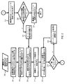
図2は、本発明の一実施形態に従って、圧力制御スキームを実装するための工程を示す簡単なフローチャートである。 FIG. 2 is a simplified flowchart illustrating steps for implementing a pressure control scheme in accordance with one embodiment of the present invention.
第1の工程202で、遅延ガス供給状況が特定される。遅延ガス供給は、多くの理由に起因しうる。一例として、遅延ガス供給は、複数のガス種が異なる時間にガスチャンバ内での平衡状態に到達しているガス組成変動として知られる条件に起因しうる。前述したように、ガス組成変動は、低圧環境および/またはキャリアガスによる流動環境で生じうる。当業者は、この状況の発生時を特定するための様々な技術を有しうる。
In the
1つの方法は、圧力時間プロファイルを測定する工程を含んでよい。処理チャンバ内に配置された測定ツールを用いることによって、処理チャンバ内の圧力が、各ガスについて測定されてよい。あるガス種が設定圧力点に到達する期間が他のガス種よりも長い場合、ガス組成変動が生じている可能性がある。 One method may include measuring a pressure time profile. By using a measurement tool located in the processing chamber, the pressure in the processing chamber may be measured for each gas. When the period during which a certain gas type reaches the set pressure point is longer than the other gas types, there is a possibility that a gas composition fluctuation has occurred.
キャリアガスによる流動環境におけるガス組成変動は、プラズマツールの構成を観察することによって特定されてもよい。一部のプラズマツールは、プロセスガス用のガスラインの下流に配置されたキャリアガス用のガスラインを有してよい。キャリアガスが下流に位置するため、プロセスガスがキャリアガスの圧力に到達できない限りは、キャリアガスは、下流の処理チャンバにプロセスガスを搬送することができない。 Variations in gas composition in the flow environment due to the carrier gas may be identified by observing the configuration of the plasma tool. Some plasma tools may have a gas line for a carrier gas disposed downstream of a gas line for a process gas. Since the carrier gas is located downstream, the carrier gas cannot transport the process gas to the downstream processing chamber unless the process gas can reach the pressure of the carrier gas.
ガス組成変動は、ガスライン構成によっても生じうる。長いガスラインは、通常、ガス供給時間を長くしうる。さらに、複数のガス種が異なる質量を有する場合、従来技術によると、重いガスは、軽いガスよりも遅い速度で流れる傾向にあるため、より遅い速度で、処理チャンバ内で平衡状態に到達しうる。追加的または代替的に、ガスライン構成は、キャリアガス(通常は、より高い流量で流れている)と適切に混合するのに十分な圧力までプロセスガスの圧力を高めるために、数多くのプロセスガス分子がガスラインの体積内に蓄積されることを必要としうる。したがって、ガスラインが長いほど、所与のガス種についての供給遅延が大きくなりうる。 Variations in gas composition can also occur due to gas line configuration. Long gas lines can usually increase gas supply time. Further, when multiple gas species have different masses, according to the prior art, heavy gases tend to flow at a slower rate than light gases, so they can reach equilibrium in the processing chamber at a slower rate. . Additionally or alternatively, a gas line configuration can be used to increase the pressure of the process gas to a pressure sufficient to adequately mix with the carrier gas (usually flowing at a higher flow rate). Molecules may need to accumulate within the volume of the gas line. Thus, the longer the gas line, the greater the supply delay for a given gas type.
次の工程204で、目標供給時間よりも遅い供給時間を有するガス種が特定されてよい。目標供給時間は通常、レシピに固有であるが、目標供給時間が10秒未満であることは珍しいことではない。一例では、1セットの分圧プロファイルを分析して、遅延供給時間を有しうるガス種のセットを特定してよい。
In the
次の工程206で、設定圧力点(すなわち、平衡圧)での所与のガス種のMFC流量(Q)が決定されてよい。一実施形態では、MFC流量は、コンダクタンス曲線を参照することによって決定されてよい。ガス種のコンダクタンス曲線は、所与の流量についてチャンバ圧力を測定することによって決定されてよい。当業者であれば、所与の設定圧力での所与のガス種の流量は、予め測定されてよく、容易に取得されうることがわかる。コンダクタンス曲線および/または流量チャートから、遅延供給時間を有しうる各ガス種について、所与の設定圧力での流量が決定されてよい。 In the next step 206, the MFC flow rate (Q) for a given gas species at a set pressure point (ie, equilibrium pressure) may be determined. In one embodiment, the MFC flow rate may be determined by referring to a conductance curve. The gas species conductance curve may be determined by measuring the chamber pressure for a given flow rate. One skilled in the art will appreciate that the flow rate of a given gas species at a given set pressure may be pre-measured and easily obtained. From the conductance curve and / or flow chart, the flow rate at a given set pressure may be determined for each gas type that may have a delayed delivery time.
次の工程208で、遅延供給ガスと特定された各ガス種のタイムスケール(τ1)が算出される。タイムスケール(τ1)を決定するための1つの方法は、固定されたスロットルバルブ開度(すなわち、一定のポンプ速度)での所与のMFC流量(Q)について処理チャンバ内の圧力上昇を追跡する方法である。
In the
次の工程210で、オーバーシュート強度(α)が、特定のMFCの特定のガス種に対して最初に設定されてよい。一実施形態では、初期オーバーシュート強度(α)は、以下の式6を用いて設定されてよい。
In a
上の式6によると、オーバーシュート強度(α)は、オーバーシュート持続時間(t0)と、遅延したガス種のタイムスケール(τ1)との関数である。一実施形態において、ガス種のオーバーシュート持続時間(t0)は、ガス流量を制御するMFCに依存してよい。通例、MFCは、遅延応答時間を有しうる。一例において、MFC制御は、40sccmの流量に切り替えられてよい。処理ツールは、MFCが新たな流量でガスを流し始めることができる前に、数秒間の遅延を経験しうる。通例、遅延は、約0.5〜2秒間であるが、個々のMFCに依存して変わりうる。したがって、オーバーシュート持続時間(t0)は、MFCの仕様に依存して変化してよい。 According to Equation 6 above, the overshoot intensity (α) is a function of the overshoot duration (t 0 ) and the time scale (τ 1 ) of the delayed gas species. In one embodiment, the gas species overshoot duration (t 0 ) may depend on the MFC controlling the gas flow rate. Typically, the MFC may have a delayed response time. In one example, MFC control may be switched to a flow rate of 40 sccm. The processing tool may experience a delay of a few seconds before the MFC can begin flowing gas at the new flow rate. Typically, the delay is about 0.5-2 seconds, but can vary depending on the individual MFC. Thus, the overshoot duration (t 0 ) may vary depending on the MFC specification.
別の実施形態において、オーバーシュート持続時間(t0)は、遅延したガス種のタイムスケール(τ1)に依存して変化してよい。前述したように、ガス種のタイムスケール(τ1)は、ガスラインの形状およびガス種の質量に依存しうる。キャリアガスによる流動環境では、ガス種のタイムスケール(τ1)は、キャリアガスの流量にも依存しうる。キャリアガスは、通常、プロセスガスよりも速い速度で流れているため、プロセスガスは、キャリアガスとうまく混合することができる前に、十分な圧力まで上昇する必要がありうる。したがって、さらなる時間遅延は、上記の式5で上述したように、プロセスガスが十分な圧力まで上昇するために必要な時間の関数である。 In another embodiment, the overshoot duration (t 0 ) may vary depending on the time scale (τ 1 ) of the delayed gas species. As described above, the time scale (τ 1 ) of the gas species can depend on the shape of the gas line and the mass of the gas species. In a flowing environment with a carrier gas, the time scale (τ 1 ) of the gas species can also depend on the flow rate of the carrier gas. Since the carrier gas is typically flowing at a faster rate than the process gas, the process gas may need to rise to a sufficient pressure before it can be mixed well with the carrier gas. Thus, the additional time delay is a function of the time required for the process gas to rise to a sufficient pressure, as described above in Equation 5 above.
次の工程212で、初期オーバーシュート強度(α)でMFC流量(Q)を修正することによって、試験運転が実行されてよい。試験運転が実行されている間に、処理チャンバ内のガス組成が測定されてよい。
In a
次の工程214で、オーバーシュート強度(α)が十分であるか否かについて判定がなされる。一実施形態では、その判定は、所定の期間(例えば、10秒間)、処理チャンバ内のガスの圧力プロファイルを追跡することによってなされてよい。
In the
所定の目標期間の圧力プロファイルに示される圧力が、平衡圧の目標精度内にある場合、オーバーシュート強度(α)は、ガスの供給遅延を最小化するために十分または最適でありうる。通常は、安定化した圧力環境を確立するために提供される時間が限られているため、所定の目標期間は、処理チャンバ圧力を安定化させるために割り当てられた時間よりも短く設定される必要がありうる。 If the pressure shown in the pressure profile for a given target period is within the target accuracy of the equilibrium pressure, the overshoot strength (α) may be sufficient or optimal to minimize the gas supply delay. Typically, the time provided for establishing a stabilized pressure environment is limited, so the predetermined target period must be set shorter than the time allotted to stabilize the process chamber pressure. There can be.
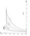
図3は、本発明の一実施形態に従って、いくつかのオーバーシュート強度(α)を示した簡単なグラフである。例えば、平衡圧が1.00に設定されている状況を考える。一実施形態において、オーバーシュート強度(α)は、チャンバ圧力が所定の目標期間で目標精度(すなわち、1%)の範囲内になった場合、最適であるとみなされる。この例において、オーバーシュート持続時間が1秒間であり、所定の目標期間がオーバーシュート持続時間の2倍(すなわち、2秒間)であるとする。図からわかるように、圧力は、目標時間(2秒間)に目標精度の範囲内の設定圧力(1.00)に到達するため、2.52のオーバーシュート強度(α)(曲線302)は、最適であるとみなされる。結果として、目標圧力精度は、ガスの圧力プロファイルが、設定圧力点にごく接近した範囲内にあり、所定の期間の前に平衡に達するように設定される。 FIG. 3 is a simple graph showing several overshoot strengths (α) according to one embodiment of the present invention. For example, consider a situation where the equilibrium pressure is set to 1.00. In one embodiment, the overshoot strength (α) is considered optimal when the chamber pressure is within target accuracy (ie, 1%) for a given target period. In this example, it is assumed that the overshoot duration is 1 second and the predetermined target period is twice the overshoot duration (that is, 2 seconds). As can be seen from the figure, the pressure reaches the set pressure (1.00) within the target accuracy range at the target time (2 seconds), so the overshoot strength (α) (curve 302) of 2.52 is Considered to be optimal. As a result, the target pressure accuracy is set so that the pressure profile of the gas is in a range very close to the set pressure point and reaches equilibrium before a predetermined period of time.
曲線304および306など、最適なオーバーシュート強度(α)が特定されない場合、次の工程216で、オーバーシュート強度(α)は、目標平衡圧力(pe)とオーバーシュート強度(α)によって実現される時間t0での圧力(p)について、以下の式7に示すように調整されてよい。工程212〜216は、反復可能であり、最適オーバーシュート強度が決定されるまで繰り返されてよい。
If the optimal overshoot strength (α) is not identified, such as
![]()
![]()
オーバーシュート強度(α)が得られた場合、次の工程218で、ガスは、最適MFCオーバーシュート強度(α*)で再び流される。
If the overshoot strength (α) is obtained, then in the
最適オーバーシュート強度が決定されてもよいが、最適オーバーシュート強度によって、MFC流量があまりに高く設定されると、誤差が生じうる。理想的には、ハードウェア(例えば、MFC)は、異常なしに機能しうる。当業者に周知のように、ほとんどのハードウェアは、極端な範囲(例えば、最大値および最小値)では設計通りに機能しない場合がある。MFCに存在しうる潜在的な誤差を考慮するために、所望の修正MFC流量は、最大MFC流量未満であってよい。次の工程220で、遅延ガス供給状況が、ハードウェア誤差を経験することなしに解決されたか否かについて判定がなされる。分析を実行するための1つの方法は、修正されたMFC流量(すなわち、Q×α*)が最大MFC流量の所定の割合(例えば、95%)未満であるか否かを計算することである。一実施形態において、所定の割合は、100%未満に設定される。最大MFC流量は、MFCの仕様によって変わりうるため、許容範囲は、実定数として設定されるのではなく、最大MFC流量の割合として設定される。
The optimal overshoot strength may be determined, but errors may occur if the MFC flow rate is set too high due to the optimal overshoot strength. Ideally, hardware (eg, MFC) can function without anomalies. As is well known to those skilled in the art, most hardware may not function as designed in extreme ranges (eg, maximum and minimum values). In order to account for potential errors that may exist in the MFC, the desired modified MFC flow may be less than the maximum MFC flow. In a
条件が満たされた場合、最適オーバーシュート強度(α*)が、特定のレシピのガス種について特定されたことになる(工程222)。 If the condition is met, the optimal overshoot intensity (α * ) has been identified for the gas species of the particular recipe (step 222).
しかし、条件が満たされない場合、次の工程224で、オーバーシュート持続時間(t0)が延長されてよい。前述したように、オーバーシュート持続時間は、処理チャンバにガスを供給する時間が増大する可能性を最小化するために、MFC応答時間に設定されてよい。しかし、修正MFC流量がMFCの最大流量に近すぎる場合、ハードウェア誤差の可能性が存在しうる。ハードウェアの限界による誤差の可能性を最小化するには、一実施形態において、オーバーシュート持続時間は、最適オーバーシュート強度を低減することによって修正MFC流量を低減するために延長される必要がありうる。
However, if the condition is not met, in the
工程208〜224は、最適オーバーシュート強度が決定されるまで反復されてよい。 Steps 208-224 may be repeated until the optimal overshoot strength is determined.
図2からわかるように、最適オーバーシュート強度(α*)は、特定のガスに対して決定されてよい。最適オーバーシュート強度(α*)を特定することによって、供給遅延が大幅に低減されうる。したがって、最適オーバーシュート強度(α*)は、1または複数のガス種のMFC流量を操作することによってガス組成変動を最小化するために用いられてよい。 As can be seen from FIG. 2, the optimal overshoot intensity (α * ) may be determined for a particular gas. By specifying the optimal overshoot strength (α * ), the supply delay can be significantly reduced. Thus, the optimal overshoot strength (α * ) may be used to minimize gas composition variation by manipulating the MFC flow rate of one or more gas species.
キャリアガスが駆動する流れについて、図2に示した方法は、ガスに関連するタイムスケールを低減しうる。しかし、上昇した圧力(tc)に関連するタイムスケールによってさらなる時間遅延が生じうることから、図2の方法は、供給遅延をさらに低減できる複数工程のオーバーシュート処理を可能にするために変形されてもよい。図4は、一実施形態において、複数工程のオーバーシュート処理を実行するための工程を示す簡単なフローチャートである。例えば、供給時間の遅いガスが、キャリアガスによる流動環境で特定される状況を考える。 For the flow driven by the carrier gas, the method shown in FIG. 2 can reduce the time scale associated with the gas. However, because the time scale associated with the increased pressure (t c ) can cause additional time delays, the method of FIG. 2 can be modified to allow multi-step overshoot processing that can further reduce supply delays. May be. FIG. 4 is a simple flowchart illustrating steps for performing a multi-step overshoot process in one embodiment. For example, consider a situation where a gas with a slow supply time is specified in a flowing environment by a carrier gas.
第1の工程402で、初期オーバーシュート強度(α)が決定される。前述したように、キャリアガスによる流動環境において、ガスラインの形状および/またはガスの分子量に起因する供給遅延に加えて、低流量プロセスガスの供給遅延も、低流量ガスが高流量キャリアガスと混合するのに十分な圧力まで上昇するために必要なタイムスケールに依存しうる。この種の供給に対処するために、一実施形態において、第1のオーバーシュート強度は、最大MFC流量に設定されてよい。
In a
次の工程404で、第1のオーバーシュート持続時間が算出される。一実施形態において、第1のオーバーシュート持続時間(すなわち、圧力上昇オーバーシュート持続時間)は、圧力上昇期間および初期オーバーシュート強度の比の関数であってよい。一実施形態において、初期オーバーシュート強度は上昇期間を最小化するために適用されるので、圧力上昇オーバーシュート持続時間は、上昇期間未満である。第1のオーバーシュート工程のオーバーシュート持続時間は、以下の式8を用いて算出されてよい。制御されない圧力プロファイル(急上昇など)を最小化するために、第1のオーバーシュート持続時間(txα)は、一実施形態では、MFC応答時間(t0)以上の値に設定されてよい。
In a
低流量プロセスガスの圧力上昇を加速した後、MFC流量は、ガスラインの形状および/またはガスの分子量に関するタイムスケールを管理するために修正されてよい。次の工程406で、第2のオーバーシュート持続時間が、単一工程オーバーシュートと同様に決定されてよい。第2のオーバーシュート持続時間は、ガスラインの形状および/またはガスの分子量に関連する時間を管理するために必要な時間であるため、一実施形態において、圧力安定化時間全体に追加されるさらなる時間を最小化するために、第2のオーバーシュート持続時間は、(図2のオーバーシュート持続時間と同じ)MFC応答時間に設定されてよい。
After accelerating the pressure rise of the low flow process gas, the MFC flow may be modified to manage the time scale for gas line geometry and / or gas molecular weight. In a
第2のオーバーシュート持続時間が決定された後、次の工程408で、第2のオーバーシュート強度が決定される。一実施形態では、第2のオーバーシュート強度は、試験運転を実行することによって決定されてよい。一実施形態において、試験運転は、初期オーバーシュート強度(すなわち、第1のオーバーシュート強度)によってMFC流量(Q)を増大させる工程を含んでよい。単一工程のオーバーシュート方法と同様に、第2のオーバーシュート強度は経験的に決定されてよい。一例において、第2のオーバーシュート強度は、(所定の目標期間のチャンバ圧力が、平衡圧の目標精度内になるように)最適オーバーシュート強度(α*)が特定されるまで調整されてよい。工程406は、図2の工程212〜216と同様である。
After the second overshoot duration is determined, in a
第2のオーバーシュート強度が決定されると、次の工程410で、別の試験運転が実行されてよい。一実施形態において、試験運転は、複数のオーバーシュート強度およびオーバーシュート持続時間を含んでよい。
Once the second overshoot intensity is determined, another test run may be performed at the
次の工程412で、遅延ガス供給状況が解決されたか否かが判定される。図2と同様に、その判定は、第1のオーバーシュート持続時間および第2のオーバーシュート持続時間にわたって修正されたMFC流量が、最大MFC流量の所定の割合の範囲内にあるか否かを判定することによってなされてよい。
In the
条件が満たされた場合、最適シュート強度(α*)が、特定のレシピのガス種について特定された(工程414)ため、処理は終了してよい。 If the condition is met, the process may end because the optimal shoot strength (α * ) has been identified for the gas species of the particular recipe (step 414).
しかし、条件が満たされない場合、次の工程416で、第2のオーバーシュート持続時間が変更されてよい。
However, if the condition is not met, the second overshoot duration may be changed in the
工程406〜416は、最適MFCスキームが決定されるまで反復されてよい。 Steps 406-416 may be repeated until the optimal MFC scheme is determined.
したがって、複数工程のオーバーシュート方法は、ガスの総供給時間に影響しうる様々なタイムスケールに対応するために、複数のオーバーシュート強度を適用することを可能にする。単一工程のオーバーシュート方法と同様に、複数工程のオーバーシュート方法は、供給遅延を短縮する修正MFC流量を決定しつつ、オーバーシュート強度を適用するために必要な時間を最小化するための方法を提供する。図2および図4に示した方法は両方とも、技術者によって手動で実行されてよい。一実施形態において、図2および図4に示したようなMFCスキームは、自動的に適用されてもよく(例えば、ソフトウェアアプリケーション)、そうすれば、人件費を削減し人的エラーのリスクを最小化することができる。 Thus, the multi-step overshoot method allows multiple overshoot intensities to be applied to accommodate various time scales that can affect the total gas supply time. Similar to the single-step overshoot method, the multi-step overshoot method is a method for minimizing the time required to apply the overshoot strength while determining a modified MFC flow rate that reduces the supply delay. I will provide a. Both the methods shown in FIGS. 2 and 4 may be performed manually by a technician. In one embodiment, MFC schemes such as those shown in FIGS. 2 and 4 may be applied automatically (eg, software applications), thereby reducing labor costs and minimizing the risk of human error. Can be
本発明の1または複数の実施形態からわかるように、ガス種のタイムスケールを管理するための方法が提供されている。最適オーバーシュート強度を決定することによって、MFC流量を調整して、ガス組成変動を大幅に低減することができる。修正されたMFC流量により、ガススループットをより良好に制御することが可能であり、それにより、不良基板の製造を減らすことができる。したがって、オーバーシュート方法は、総処理時間をほとんどまたは全く延長することなく、より高品質の基板を製造するための安価な解決策を提供する。 As can be seen from one or more embodiments of the present invention, a method for managing the time scale of a gas species is provided. By determining the optimal overshoot strength, the MFC flow rate can be adjusted to greatly reduce gas composition fluctuations. With a modified MFC flow rate, the gas throughput can be better controlled, thereby reducing the production of defective substrates. Thus, the overshoot method provides an inexpensive solution for producing higher quality substrates with little or no total processing time.
以上、いくつかの好ましい実施形態を参照しつつ本発明を説明したが、本発明の範囲内で、種々の代替物、置換物、および、等価物が可能である。本明細書では様々な例を提供したが、これらの例は、例示を目的としたものであり、本発明を限定するものではない。 Although the invention has been described with reference to certain preferred embodiments, various alternatives, substitutions, and equivalents are possible within the scope of the invention. While various examples have been provided herein, these examples are for illustrative purposes and are not intended to limit the invention.
また、発明の名称および発明の概要は、便宜上、本明細書で提供されているものであり、特許請求の範囲を解釈するために用いられるべきものではない。さらに、要約書は、非常に簡潔に書かれており、便宜上、提供されているものであるため、特許請求の範囲に記載された発明全体を解釈または限定するために用いられるべきではない。「セット(組)」という用語が用いられている場合には、かかる用語は、一般的に理解される数学的な意味を持ち、0、1、または、2以上の要素を網羅するよう意図されている。また、本発明の方法および装置を実施する他の態様が数多く存在することにも注意されたい。したがって、以下に示す特許請求の範囲は、本発明の真の趣旨および範囲内に含まれる代替物、置換物、および、等価物の全てを網羅するものとして解釈される。 In addition, the title of the invention and the summary of the invention are provided in this specification for convenience, and should not be used to interpret the scope of the claims. Further, the abstract is written very briefly and is provided for convenience, and should not be used to interpret or limit the entire claimed invention. Where the term “set” is used, such term has a generally understood mathematical meaning and is intended to cover zero, one, or two or more elements. ing. It should also be noted that there are many other ways of implementing the method and apparatus of the present invention. Accordingly, the following claims are to be construed as covering all alternatives, substitutions, and equivalents included within the true spirit and scope of the present invention.
Claims (20)
前記方法は、
前記レシピの実行中に利用され、目標供給タイムスケールよりも遅い1組の供給時間を有する1組の遅延ガス種を特定する工程と、
前記1組の遅延ガス種に含まれる各ガス種の初期オーバーシュート強度を確立する工程であって、前記初期オーバーシュート強度は、MFC流量を増大させるための因子である、工程と、
前記1組の遅延ガス種に含まれる前記各ガス種の初期オーバーシュート持続時間を決定する工程であって、前記初期オーバーシュート持続時間は、前記初期オーバーシュート強度を前記MFC流量に適用する持続時間である、工程と、
前記1組の遅延ガス種に含まれる前記各ガス種のMFCハードウェアを調整して前記レシピを実行することによって前記MFC制御スキームを確立する工程と、を備え、
前記MFCハードウェアの調整は、前記MFC制御スキームが、前記1組の遅延ガス種に含まれる前記各ガス種に、前記処理チャンバの平衡圧の目標精度の範囲内にある圧力プロファイルを提供するか否かを判定するために、前記初期オーバーシュート強度を前記初期オーバーシュート持続時間にわたって適用することを含む、方法。 A method for determining a mass flow controller (MFC) control scheme for a recipe, wherein the MFC control scheme is configured to reduce a time scale of gas supply into a processing chamber of a plasma processing system,
The method
Identifying a set of delayed gas species utilized during execution of the recipe and having a set of supply times slower than a target supply time scale;
Establishing an initial overshoot strength for each gas species included in the set of delayed gas species, wherein the initial overshoot strength is a factor for increasing the MFC flow rate; and
Determining an initial overshoot duration of each gas species included in the set of delayed gas species, wherein the initial overshoot duration is a duration of applying the initial overshoot intensity to the MFC flow rate; A process,
Establishing the MFC control scheme by adjusting the MFC hardware of each gas type included in the set of delayed gas types and executing the recipe; and
The adjustment of the MFC hardware is such that the MFC control scheme provides a pressure profile for each gas species included in the set of delayed gas species that is within a target accuracy range of the equilibrium pressure of the processing chamber. Applying the initial overshoot intensity over the initial overshoot duration to determine whether or not.
前記1組の遅延ガス種に含まれる前記各ガス種の前記MFC流量を特定する工程と、
前記1組の遅延ガス種に含まれる前記各ガス種のタイムスケールを決定する工程と、を備え、
前記タイムスケールは、ガスラインの形状、前記各ガス種の質量、および、前記各ガス種の前記MFC流量のうちの少なくとも1つの関数である、方法。 The method of claim 1, further comprising:
Identifying the MFC flow rate of each gas species included in the set of delayed gas species;
Determining a time scale of each gas species included in the set of delayed gas species,
The method is a method, wherein the time scale is a function of at least one of a shape of a gas line, a mass of each gas species, and the MFC flow rate of each gas species.
前記初期オーバーシュート持続時間は、前記MFCハードウェアの遅延応答時間と、前記1組の遅延ガス種に含まれる前記各ガス種のタイムスケールと、の内の少なくとも一方の因子であり、
前記タイムスケールは、ガスラインの形状、前記各ガス種の質量、および、前記各ガス種の前記MFC流量のうちの少なくとも1つの関数である、方法。 The method of claim 1, comprising:
The initial overshoot duration is a factor of at least one of a delayed response time of the MFC hardware and a time scale of each gas species included in the set of delayed gas species,
The method is a method, wherein the time scale is a function of at least one of a shape of a gas line, a mass of each gas species, and the MFC flow rate of each gas species.
前記初期オーバーシュート強度は、前記初期オーバーシュート持続時間と、前記1組の遅延ガス種に含まれる前記各ガス種のタイムスケールとの関数であり、
前記タイムスケールは、ガスラインの形状、前記各ガス種の質量、および、前記各ガス種の前記MFC流量のうちの少なくとも1つの関数である、方法。 The method of claim 1, comprising:
The initial overshoot intensity is a function of the initial overshoot duration and the time scale of each gas species included in the set of delayed gas species,
The method is a method, wherein the time scale is a function of at least one of a shape of a gas line, a mass of each gas species, and the MFC flow rate of each gas species.
前記1組の遅延ガス種に含まれる前記各ガス種の前記圧力プロファイルが、前記処理チャンバの前記平衡圧の前記目標精度の範囲内にない場合に、前記初期オーバーシュート強度を調整する工程を備える、方法。 The method of claim 1, further comprising:
Adjusting the initial overshoot strength when the pressure profile of each gas type included in the set of retarded gas types is not within the target accuracy range of the equilibrium pressure of the processing chamber. ,Method.
前記1組の遅延ガス種に含まれる前記各ガス種の前記初期オーバーシュート持続時間は、調整されたMFC流量が前記MFCハードウェアの最大MFC流量の所定の割合よりも大きい場合に修正され、
前記調整されたMFC流量は、前記初期オーバーシュート持続時間にわたって前記初期オーバーシュート強度によって修正された前記MFC流量である、方法。 6. A method according to claim 5, wherein
The initial overshoot duration of each gas type included in the set of delayed gas types is modified when the adjusted MFC flow rate is greater than a predetermined percentage of the maximum MFC flow rate of the MFC hardware;
The adjusted MFC flow rate is the MFC flow rate modified by the initial overshoot intensity over the initial overshoot duration.
前記初期オーバーシュート強度が前記平衡圧の前記目標精度の範囲内にあり、前記調整されたMFC流量が、前記MFCハードウェアの前記最大MFC流量の前記所定の割合よりも小さいときに、前記1組の遅延ガス種に含まれる前記各ガス種の最適オーバーシュート強度が決定される、方法。 The method of claim 6, comprising:
When the initial overshoot strength is within the target accuracy range of the equilibrium pressure and the adjusted MFC flow rate is less than the predetermined percentage of the maximum MFC flow rate of the MFC hardware The optimum overshoot intensity of each gas species included in the delayed gas species is determined.
前記方法は、
前記レシピの実行中に利用され、目標供給タイムスケールよりも遅い1組の供給時間を有する1組の遅延ガス種を特定する工程と、
前記1組の遅延ガス種に含まれる各ガス種の初期オーバーシュート強度を確立する工程であって、前記初期オーバーシュート強度は、初期オーバーシュート持続時間中にMFC流量を増大させる第1の因子であり、前記初期オーバーシュート持続時間は、前記MFC流量に前記初期オーバーシュート強度を適用するための第1の持続時間である、工程と、
前記1組の遅延ガス種に含まれる前記各ガス種の第2のオーバーシュート強度を確立する工程であって、前記第2のオーバーシュート強度は、第2のオーバーシュート持続時間中に前記MFC流量を増大させる第2の因子であり、前記第2のオーバーシュート持続時間は、前記MFC流量に前記第2のオーバーシュート強度を適用するための第2の持続時間である、工程と、
前記1組の遅延ガス種に含まれる前記各ガス種のためのMFCハードウェアを調整して前記レシピを実行することによって前記MFC制御スキームを確立する工程と、
を備え、
前記MFCハードウェアの調整は、前記MFC制御スキームが、前記1組の遅延ガス種に含まれる前記各ガス種に、前記処理チャンバの平衡圧の目標精度の範囲内にある圧力プロファイルを提供するか否かを判定するために、前記初期オーバーシュート強度および前記第2のオーバーシュート強度を適用することを含む、方法。 A method of establishing a mass flow controller (MFC) control scheme for a recipe, wherein the MFC control scheme is configured to reduce a time scale of gas supply into a processing chamber of a plasma processing system,
The method
Identifying a set of delayed gas species utilized during execution of the recipe and having a set of supply times slower than a target supply time scale;
Establishing an initial overshoot strength for each gas species included in the set of delayed gas species, wherein the initial overshoot strength is a first factor that increases the MFC flow rate during the initial overshoot duration. The initial overshoot duration is a first duration for applying the initial overshoot intensity to the MFC flow rate; and
Establishing a second overshoot strength for each gas species included in the set of retarded gas species, wherein the second overshoot strength is determined during the second overshoot duration. And the second overshoot duration is a second duration for applying the second overshoot intensity to the MFC flow rate; and
Establishing the MFC control scheme by adjusting MFC hardware for each gas species included in the set of retarded gas species and executing the recipe;
With
The adjustment of the MFC hardware is such that the MFC control scheme provides a pressure profile for each gas species included in the set of delayed gas species that is within a target accuracy range of the equilibrium pressure of the processing chamber. Applying the initial overshoot strength and the second overshoot strength to determine whether or not.
前記1組の遅延ガス種に含まれる前記各ガス種の前記MFC流量を特定する工程と、
前記1組の遅延ガス種に含まれる前記各ガス種のタイムスケールを決定する工程と、を備え、
前記タイムスケールは、ガスラインの形状、前記各ガス種の質量、および、前記各ガス種の前記MFC流量の内の少なくとも1つの関数である、方法。 The method of claim 8, further comprising:
Identifying the MFC flow rate of each gas species included in the set of delayed gas species;
Determining a time scale of each gas species included in the set of delayed gas species,
The time scale is a method that is a function of at least one of a gas line shape, a mass of each gas species, and the MFC flow rate of each gas species.
前記各ガス種の前記初期オーバーシュート強度は、前記MFCハードウェアの最大MFC流量に設定される、方法。 The method of claim 9, comprising:
The method, wherein the initial overshoot intensity of each gas type is set to a maximum MFC flow rate of the MFC hardware.
前記各ガス種の前記初期オーバーシュート持続時間は、前記初期オーバーシュート強度および圧力上昇期間の因子であり、
前記圧力上昇期間は、前記各ガス種の圧力がキャリアガスの圧力と少なくとも同じになるために増大されている期間であり、前記キャリアガスは、前記各ガス種よりも高い流量で流れる、方法。 The method of claim 10, comprising:
The initial overshoot duration of each gas species is a factor of the initial overshoot intensity and pressure rise period,
The pressure increase period is a period in which the pressure of each gas species is increased to be at least the same as the pressure of the carrier gas, and the carrier gas flows at a higher flow rate than the gas species.
前記第2のオーバーシュート持続時間は、前記MFCハードウェアの遅延応答時間の因子である、方法。 The method of claim 11, comprising:
The method, wherein the second overshoot duration is a factor in the delayed response time of the MFC hardware.
前記第2のオーバーシュート強度は、前記初期オーバーシュート強度に設定され、
前記第2のオーバーシュート強度は、収集された経験的データを適用することによって調整され、
前記第2のオーバーシュート強度は、前記1組の遅延ガス種に含まれる前記各ガス種の前記圧力プロファイルが、前記処理チャンバの前記平衡圧の前記目標精度の範囲内にない場合に、調整される、方法。 The method of claim 12, comprising:
The second overshoot strength is set to the initial overshoot strength,
The second overshoot intensity is adjusted by applying the collected empirical data;
The second overshoot intensity is adjusted when the pressure profile of each gas species included in the set of delayed gas species is not within the target accuracy range of the equilibrium pressure of the processing chamber. The way.
前記1組の遅延ガス種に含まれる前記各ガス種の前記第2のオーバーシュート持続時間は、前記第2のオーバーシュート強度および前記第2のオーバーシュート持続時間に基づいて調整されたMFC流量が、前記MFCハードウェアの前記最大MFC流量の所定の割合より大きい場合に、調整される、方法。 14. A method according to claim 13, comprising:
The second overshoot duration of each of the gas types included in the set of delayed gas species is an MFC flow rate adjusted based on the second overshoot intensity and the second overshoot duration. , Adjusted if greater than a predetermined percentage of the maximum MFC flow rate of the MFC hardware.
前記第2のオーバーシュート強度が前記平衡圧の前記目標精度の範囲内にあり、前記調整されたMFC流量が、前記MFCハードウェアの前記最大MFC流量の前記所定の割合よりも小さいときに、前記1組の遅延ガス種に含まれる前記各ガス種の最適オーバーシュート強度が決定される、方法。 15. A method according to claim 14, comprising
When the second overshoot strength is within the target accuracy range of the equilibrium pressure and the adjusted MFC flow rate is less than the predetermined percentage of the maximum MFC flow rate of the MFC hardware; A method in which an optimal overshoot intensity for each gas species included in a set of delayed gas species is determined.
前記レシピの前記実行中に利用され、目標供給タイムスケールよりも遅い1組の供給時間を有する1組の遅延ガス種を特定する工程と、
各ガス種の初期オーバーシュート強度を確立する工程であって、前記初期オーバーシュート強度は、マスフローコントローラ(MFC)流量を増大させるための因子である、工程と、
前記各ガス種の初期オーバーシュート持続時間を決定する工程であって、前記初期オーバーシュート持続時間は、前記初期オーバーシュート強度を前記各ガス種の前記MFC流量に適用する持続時間である、工程と、
前記初期オーバーシュート持続時間にわたって前記初期オーバーシュート強度を適用することによって調整された前記各ガス種のMFC流量を用いて前記レシピを実行する工程と、
前記初期オーバーシュート強度が前記最適オーバーシュート強度であるか否かを判定するために、前記レシピの前記実行中に確立された前記各ガス種の圧力プロファイルを、前記処理チャンバの平衡圧の目標精度と比較する工程と、
前記各ガス種の前記圧力プロファイルが、前記処理チャンバの前記平衡圧の前記目標精度の範囲内にない場合に、前記初期オーバーシュート強度を調整する工程と、を備える、方法。 A method for determining an optimal overshoot intensity to reduce a gas supply time scale into a processing chamber of a plasma processing system during execution of a recipe comprising:
Identifying a set of delayed gas species utilized during the execution of the recipe and having a set of supply times slower than a target supply time scale;
Establishing an initial overshoot strength for each gas species, wherein the initial overshoot strength is a factor for increasing a mass flow controller (MFC) flow rate; and
Determining an initial overshoot duration for each gas species, wherein the initial overshoot duration is a duration for applying the initial overshoot intensity to the MFC flow rate for each gas species; ,
Executing the recipe using the MFC flow rate of each gas species adjusted by applying the initial overshoot intensity over the initial overshoot duration;
In order to determine whether the initial overshoot strength is the optimal overshoot strength, the pressure profile of each gas species established during the execution of the recipe is obtained from the target chamber equilibrium pressure target accuracy. And a process of comparing with
Adjusting the initial overshoot intensity when the pressure profile of each gas species is not within the target accuracy range of the equilibrium pressure of the processing chamber.
前記1組の遅延ガス種に含まれる前記各ガス種の前記MFC流量を特定する工程と、
前記1組の遅延ガス種に含まれる前記各ガス種のタイムスケールを決定する工程と、を備え、
前記タイムスケールは、ガスラインの形状、前記各ガス種の質量、および、前記各ガス種の前記MFC流量の内の少なくとも1つの関数である、方法。 The method of claim 16, further comprising:
Identifying the MFC flow rate of each gas species included in the set of delayed gas species;
Determining a time scale of each gas species included in the set of delayed gas species,
The time scale is a method that is a function of at least one of a gas line shape, a mass of each gas species, and the MFC flow rate of each gas species.
前記初期オーバーシュート強度は、前記1組の遅延ガス種に含まれる前記各ガス種の前記初期オーバーシュート持続時間および前記タイムスケールの関数である、方法。 The method of claim 17, comprising:
The initial overshoot intensity is a function of the initial overshoot duration and the time scale for each gas species included in the set of delayed gas species.
前記1組の遅延ガス種の前記各ガス種の前記初期オーバーシュート持続時間は、前記調整されたMFC流量がMFCハードウェアの最大MFC流量の所定の割合よりも大きい場合に、修正される、方法。 The method according to claim 18, comprising:
The initial overshoot duration of each gas type of the set of delayed gas types is modified when the adjusted MFC flow rate is greater than a predetermined percentage of the maximum MFC flow rate of MFC hardware. .
前記初期オーバーシュート強度が前記平衡圧の前記目標精度の範囲内にあり、前記調整されたMFC流量が、前記MFCハードウェアの前記最大MFC流量の前記所定の割合よりも小さいときに、前記1組の遅延ガス種に含まれる前記各ガス種の前記最適オーバーシュート強度が決定される、方法。 20. The method according to claim 19, comprising
When the initial overshoot strength is within the target accuracy range of the equilibrium pressure and the adjusted MFC flow rate is less than the predetermined percentage of the maximum MFC flow rate of the MFC hardware The optimal overshoot intensity of each gas species included in the delayed gas species is determined.
Applications Claiming Priority (5)
| Application Number | Priority Date | Filing Date | Title |
|---|---|---|---|
| US7453908P | 2008-06-20 | 2008-06-20 | |
| US61/074,539 | 2008-06-20 | ||
| US12/477,196 | 2009-06-03 | ||
| US12/477,196 US8340827B2 (en) | 2008-06-20 | 2009-06-03 | Methods for controlling time scale of gas delivery into a processing chamber |
| PCT/US2009/047279 WO2009155221A2 (en) | 2008-06-20 | 2009-06-12 | Methods for controlling time scale of gas delivery into a processing chamber |
Publications (2)
| Publication Number | Publication Date |
|---|---|
| JP2011524948A true JP2011524948A (en) | 2011-09-08 |
| JP2011524948A5 JP2011524948A5 (en) | 2014-02-06 |
Family
ID=41432039
Family Applications (1)
| Application Number | Title | Priority Date | Filing Date |
|---|---|---|---|
| JP2011514723A Pending JP2011524948A (en) | 2008-06-20 | 2009-06-12 | Method for controlling the time scale of gas supply into a processing chamber |
Country Status (6)
| Country | Link |
|---|---|
| US (1) | US8340827B2 (en) |
| JP (1) | JP2011524948A (en) |
| KR (1) | KR20110019376A (en) |
| CN (1) | CN102067280B (en) |
| TW (1) | TWI477938B (en) |
| WO (1) | WO2009155221A2 (en) |
Families Citing this family (23)
| Publication number | Priority date | Publication date | Assignee | Title |
|---|---|---|---|---|
| JP5346628B2 (en) * | 2009-03-11 | 2013-11-20 | 株式会社堀場エステック | Mass flow controller verification system, verification method, verification program |
| US8770215B1 (en) * | 2011-07-20 | 2014-07-08 | Daniel T. Mudd | Low flow injector to deliver a low flow of gas to a remote location |
| US9958302B2 (en) | 2011-08-20 | 2018-05-01 | Reno Technologies, Inc. | Flow control system, method, and apparatus |
| US9188989B1 (en) | 2011-08-20 | 2015-11-17 | Daniel T. Mudd | Flow node to deliver process gas using a remote pressure measurement device |
| WO2014040002A2 (en) | 2012-09-10 | 2014-03-13 | Mudd Daniel T | Pressure based mass flow controller |
| DE102013109210A1 (en) * | 2013-08-20 | 2015-02-26 | Aixtron Se | Evacuable chamber, in particular with a purge gas flushable loading sluice |
| US10128087B2 (en) | 2014-04-07 | 2018-11-13 | Lam Research Corporation | Configuration independent gas delivery system |
| US9580360B2 (en) | 2014-04-07 | 2017-02-28 | Lam Research Corporation | Monolithic ceramic component of gas delivery system and method of making and use thereof |
| US10557197B2 (en) | 2014-10-17 | 2020-02-11 | Lam Research Corporation | Monolithic gas distribution manifold and various construction techniques and use cases therefor |
| US10022689B2 (en) | 2015-07-24 | 2018-07-17 | Lam Research Corporation | Fluid mixing hub for semiconductor processing tool |
| US10118263B2 (en) | 2015-09-02 | 2018-11-06 | Lam Researech Corporation | Monolithic manifold mask and substrate concepts |
| US10215317B2 (en) | 2016-01-15 | 2019-02-26 | Lam Research Corporation | Additively manufactured gas distribution manifold |
| US9879795B2 (en) | 2016-01-15 | 2018-01-30 | Lam Research Corporation | Additively manufactured gas distribution manifold |
| US10453721B2 (en) | 2016-03-15 | 2019-10-22 | Applied Materials, Inc. | Methods and assemblies for gas flow ratio control |
| US10679880B2 (en) | 2016-09-27 | 2020-06-09 | Ichor Systems, Inc. | Method of achieving improved transient response in apparatus for controlling flow and system for accomplishing same |
| US11144075B2 (en) | 2016-06-30 | 2021-10-12 | Ichor Systems, Inc. | Flow control system, method, and apparatus |
| US10838437B2 (en) | 2018-02-22 | 2020-11-17 | Ichor Systems, Inc. | Apparatus for splitting flow of process gas and method of operating same |
| US10303189B2 (en) | 2016-06-30 | 2019-05-28 | Reno Technologies, Inc. | Flow control system, method, and apparatus |
| JP6762218B2 (en) * | 2016-12-13 | 2020-09-30 | 株式会社堀場エステック | Flow rate calculation system and flow rate calculation method |
| US10663337B2 (en) | 2016-12-30 | 2020-05-26 | Ichor Systems, Inc. | Apparatus for controlling flow and method of calibrating same |
| US10866135B2 (en) * | 2018-03-26 | 2020-12-15 | Applied Materials, Inc. | Methods, systems, and apparatus for mass flow verification based on rate of pressure decay |
| US11841715B2 (en) * | 2020-10-22 | 2023-12-12 | Applied Materials, Inc. | Piezo position control flow ratio control |
| JP2024512898A (en) | 2021-03-03 | 2024-03-21 | アイコール・システムズ・インク | Fluid flow control system with manifold assembly |
Citations (1)
| Publication number | Priority date | Publication date | Assignee | Title |
|---|---|---|---|---|
| JP2007208194A (en) * | 2006-02-06 | 2007-08-16 | Tokyo Electron Ltd | Gas supply apparatus and method, and substrate processing apparatus |
Family Cites Families (18)
| Publication number | Priority date | Publication date | Assignee | Title |
|---|---|---|---|---|
| US6193811B1 (en) * | 1999-03-03 | 2001-02-27 | Applied Materials, Inc. | Method for improved chamber bake-out and cool-down |
| EP1096351A4 (en) * | 1999-04-16 | 2004-12-15 | Fujikin Kk | Parallel bypass type fluid feeding device, and method and device for controlling fluid variable type pressure system flow rate used for the device |
| US6363958B1 (en) * | 1999-05-10 | 2002-04-02 | Parker-Hannifin Corporation | Flow control of process gas in semiconductor manufacturing |
| US6632322B1 (en) * | 2000-06-30 | 2003-10-14 | Lam Research Corporation | Switched uniformity control |
| US7354555B2 (en) * | 2002-05-08 | 2008-04-08 | Taiwan Semiconductor Manufacturing Co., Ltd. | Gas flow control system with interlock |
| WO2005102432A1 (en) * | 2004-04-23 | 2005-11-03 | Boehm Stephan | Method and apparatus for changing the concentration of a target gas at the blood compartment of a patient's lung during artificial ventilation |
| US7216019B2 (en) * | 2004-07-08 | 2007-05-08 | Celerity, Inc. | Method and system for a mass flow controller with reduced pressure sensitivity |
| US7412986B2 (en) * | 2004-07-09 | 2008-08-19 | Celerity, Inc. | Method and system for flow measurement and validation of a mass flow controller |
| WO2006043551A1 (en) * | 2004-10-19 | 2006-04-27 | Tokyo Electron Limited | Plasma sputtering film deposition method and equipment |
| US7756599B2 (en) * | 2004-10-28 | 2010-07-13 | Tokyo Electron Limited | Substrate processing apparatus, program for performing operation and control method thereof, and computer readable storage medium storing the program |
| US7368000B2 (en) * | 2004-12-22 | 2008-05-06 | The Boc Group Plc | Treatment of effluent gases |
| US7854821B2 (en) * | 2005-06-02 | 2010-12-21 | Tokyo Electron Limited | Substrate processing apparatus |
| US20070021935A1 (en) * | 2005-07-12 | 2007-01-25 | Larson Dean J | Methods for verifying gas flow rates from a gas supply system into a plasma processing chamber |
| US7896967B2 (en) * | 2006-02-06 | 2011-03-01 | Tokyo Electron Limited | Gas supply system, substrate processing apparatus and gas supply method |
| US8304328B2 (en) * | 2006-03-20 | 2012-11-06 | Hitachi Kokusai Electric Inc. | Manufacturing method of semiconductor device and substrate processing apparatus |
| US20080153311A1 (en) * | 2006-06-28 | 2008-06-26 | Deenesh Padhi | Method for depositing an amorphous carbon film with improved density and step coverage |
| JP5028193B2 (en) * | 2007-09-05 | 2012-09-19 | 株式会社日立ハイテクノロジーズ | Method for conveying object to be processed in semiconductor manufacturing apparatus |
| US20090084987A1 (en) * | 2007-09-28 | 2009-04-02 | Varian Semiconductor Equipment Associates, Inc. | Charge neutralization in a plasma processing apparatus |
-
2009
- 2009-06-03 US US12/477,196 patent/US8340827B2/en active Active
- 2009-06-12 KR KR1020107028548A patent/KR20110019376A/en not_active Application Discontinuation
- 2009-06-12 JP JP2011514723A patent/JP2011524948A/en active Pending
- 2009-06-12 CN CN2009801243953A patent/CN102067280B/en active Active
- 2009-06-12 WO PCT/US2009/047279 patent/WO2009155221A2/en active Application Filing
- 2009-06-19 TW TW098120734A patent/TWI477938B/en active
Patent Citations (1)
| Publication number | Priority date | Publication date | Assignee | Title |
|---|---|---|---|---|
| JP2007208194A (en) * | 2006-02-06 | 2007-08-16 | Tokyo Electron Ltd | Gas supply apparatus and method, and substrate processing apparatus |
Also Published As
| Publication number | Publication date |
|---|---|
| TW201017357A (en) | 2010-05-01 |
| WO2009155221A2 (en) | 2009-12-23 |
| WO2009155221A3 (en) | 2010-03-25 |
| CN102067280A (en) | 2011-05-18 |
| KR20110019376A (en) | 2011-02-25 |
| TWI477938B (en) | 2015-03-21 |
| US20090319071A1 (en) | 2009-12-24 |
| US8340827B2 (en) | 2012-12-25 |
| CN102067280B (en) | 2013-04-03 |
Similar Documents
| Publication | Publication Date | Title |
|---|---|---|
| JP2011524948A (en) | Method for controlling the time scale of gas supply into a processing chamber | |
| US10655220B2 (en) | Gas control system, deposition apparatus including gas control system, and program and gas control method used for gas control system | |
| US20230317471A1 (en) | Fluid control system | |
| TWI737630B (en) | Dynamic precursor dosing for atomic layer deposition | |
| US20060080041A1 (en) | Chemical mixing apparatus, system and method | |
| US11519070B2 (en) | Vaporization device, film formation device, program for a concentration control mechanism, and concentration control method | |
| US11520358B2 (en) | Gas-pulsing-based shared precursor distribution system and methods of use | |
| US10031007B2 (en) | Method of calculating output flow rate of flow rate controller | |
| US20160003665A1 (en) | System and method to automatically self-adjust a valve pedestal of a mass flow controller | |
| JP6556850B2 (en) | Gas multiple supply method and gas multiple supply apparatus | |
| US10248137B2 (en) | Method for controlling flow rate of fluid, mass flow rate control device for executing method, and mass flow rate control system utilizing mass flow rate control device | |
| EP0844479A2 (en) | Method for rapidly determining an impurity level in a gas source or a gas distribution system | |
| TW202129807A (en) | System for stabilizing gas flow inputted to sensor | |
| CN113899194B (en) | Drying method and drying system for electrode plate of secondary battery | |
| US20050026460A1 (en) | Optimized temperature controller for cold mass introduction | |
| US10845119B2 (en) | Method of arranging treatment process | |
| JPH05315290A (en) | Gas flow rate controller | |
| US20210156027A1 (en) | Liquid source vaporization apparatus, control method for a liquid source vaporization apparatus and program recording medium on which is recorded a program for a liquid source vaporization apparatus | |
| US20230129479A1 (en) | Flow rate control device and flow rate control method | |
| EP4293470A1 (en) | Dynamic method for rapidly filling identical batches of bottles with high metrological precision gas mixtures | |
| JPH11286782A (en) | Substrate treating device |
Legal Events
| Date | Code | Title | Description |
|---|---|---|---|
| A621 | Written request for application examination |
Free format text: JAPANESE INTERMEDIATE CODE: A621 Effective date: 20120606 |
|
| A131 | Notification of reasons for refusal |
Free format text: JAPANESE INTERMEDIATE CODE: A131 Effective date: 20130917 |
|
| A524 | Written submission of copy of amendment under section 19 (pct) |
Free format text: JAPANESE INTERMEDIATE CODE: A524 Effective date: 20131211 |
|
| A02 | Decision of refusal |
Free format text: JAPANESE INTERMEDIATE CODE: A02 Effective date: 20140708 |