KR20110019376A - Methods for controlling time scale of gas delivery into a processing chamber - Google Patents
Methods for controlling time scale of gas delivery into a processing chamber Download PDFInfo
- Publication number
- KR20110019376A KR20110019376A KR1020107028548A KR20107028548A KR20110019376A KR 20110019376 A KR20110019376 A KR 20110019376A KR 1020107028548 A KR1020107028548 A KR 1020107028548A KR 20107028548 A KR20107028548 A KR 20107028548A KR 20110019376 A KR20110019376 A KR 20110019376A
- Authority
- KR
- South Korea
- Prior art keywords
- gas species
- mfc
- overshoot
- flow rate
- gas
- Prior art date
Links
Images


Classifications
-
- G—PHYSICS
- G05—CONTROLLING; REGULATING
- G05D—SYSTEMS FOR CONTROLLING OR REGULATING NON-ELECTRIC VARIABLES
- G05D7/00—Control of flow
- G05D7/06—Control of flow characterised by the use of electric means
- G05D7/0617—Control of flow characterised by the use of electric means specially adapted for fluid materials
- G05D7/0629—Control of flow characterised by the use of electric means specially adapted for fluid materials characterised by the type of regulator means
- G05D7/0635—Control of flow characterised by the use of electric means specially adapted for fluid materials characterised by the type of regulator means by action on throttling means
-
- Y—GENERAL TAGGING OF NEW TECHNOLOGICAL DEVELOPMENTS; GENERAL TAGGING OF CROSS-SECTIONAL TECHNOLOGIES SPANNING OVER SEVERAL SECTIONS OF THE IPC; TECHNICAL SUBJECTS COVERED BY FORMER USPC CROSS-REFERENCE ART COLLECTIONS [XRACs] AND DIGESTS
- Y10—TECHNICAL SUBJECTS COVERED BY FORMER USPC
- Y10T—TECHNICAL SUBJECTS COVERED BY FORMER US CLASSIFICATION
- Y10T137/00—Fluid handling
- Y10T137/7722—Line condition change responsive valves
- Y10T137/7758—Pilot or servo controlled
- Y10T137/7761—Electrically actuated valve
Landscapes
- Physics & Mathematics (AREA)
- General Physics & Mathematics (AREA)
- Engineering & Computer Science (AREA)
- Automation & Control Theory (AREA)
- Drying Of Semiconductors (AREA)
- Chemical Vapour Deposition (AREA)
- Feeding, Discharge, Calcimining, Fusing, And Gas-Generation Devices (AREA)
- Physical Or Chemical Processes And Apparatus (AREA)
- Accessories For Mixers (AREA)
Abstract
한 레시피가 제공되었을 때, 처리 챔버에 가스 전달 시간 스케일을 줄일 수 있게 구성된 유량 제어기 (MFC) 제어 방식을 위한 하나의 방법이다. 상기 방법은 전달 시간이 목표 전달 시간 스케일보다 더 늦은 시간 세트를 갖는 상기 레시피를 수행하면서 지연된 가스 종을 식별하는 것을 포함한다. 상기 방법은 또한 지연되는 가스 종들 세트의 각각의 가스 종들의 초기 오버슈트의 크기와 초기 오버슈트의 지속 시간을 설정하는 것을 포함한다. 상기 방법은 더 나아가 제조 방법을 수행하는 중에 각각의 가스 종을 위해 MFC 하드웨어를 조정하는 MFC 제어 스킴을 설정하는 것을 포함한다. MFC 하드웨어를 조정하는 것은 초기 오버슈트 기간에서 초기 오버슈트 강도를 적용하여서, MFC 제어 스킴이 각각의 가스 종들에 평형 압력의 목표 정확도 범위 내의 압력 프로파일을 제공하는지를 결정하는 것이다. When a recipe is provided, it is one method for a flow controller (MFC) control scheme configured to reduce the gas delivery time scale to the processing chamber. The method includes identifying a gas species that has been delayed while performing the recipe having a time set whose delivery time is later than the target delivery time scale. The method also includes setting the size of the initial overshoot and the duration of the initial overshoot of each of the gas species of the set of delayed gas species. The method further includes setting up an MFC control scheme that adjusts the MFC hardware for each gas species while performing the manufacturing method. Adjusting the MFC hardware is to apply the initial overshoot strength in the initial overshoot period to determine if the MFC control scheme provides each gas species with a pressure profile within the target accuracy range of the equilibrium pressure.

Description
플라즈마 처리는 반도체 산업의 진보를 촉진시켜왔다. 경쟁적인 반도체 산업에서, 만약 제조 업체가 양질의 디바이스를 생산하기 위해 처리량을 극대화할 수 있는 능력이 있다면 경쟁 우위를 얻을 수 있을 것이다. 처리량을 제어하는 하나의 방법은 처리 챔버로의 가스의 흐름을 제어하는 것이다.Plasma processing has promoted the progress of the semiconductor industry. In the competitive semiconductor industry, if manufacturers have the ability to maximize throughput to produce quality devices, they will have a competitive advantage. One way to control throughput is to control the flow of gas into the processing chamber.
일반적으로, 기판 처리에서, 레시피는 2개 이상의 가스 종들을 요구할 수도 있다. 이상적으로, 가스 종은 혼합되고 처리 챔버에서 동시에 평형 압력 상태 (예를 들어, 설정 압력) 에 도달한다. 그러나, 수개의 인자들이 상기 가스 종들이 상이한 시간 스케일 (time scale) (즉, 전달 시간) 를 갖게 할 수도 있다.In general, in substrate processing, a recipe may require two or more gas species. Ideally, gas species are mixed and reach an equilibrium pressure state (eg, set pressure) simultaneously in the processing chamber. However, several factors may cause the gas species to have different time scales (ie, delivery times).
가스 전달 시간에 영향을 주는 하나의 인자가 가스 종의 질량이다. 당업자는 무거운 분자량을 가진 가스 종은 가벼운 분자량을 가진 가스 종보다 천천히 이동한다는 것을 알고 있다. 가스 종들 간의 질량의 차이는 저압 환경에서 각 가스 종의 유속에 영향을 미칠 수 있다. 저압 환경에서, 가스 흐름은 분자일 수도 있고 각각의 가스 종은 사실상 서로 영향을 받지 않는다. 그 결과로, 가스 종의 분리가 발생할 수 있어 가스 조성 드리프트를 야기시킨다. 즉, 상기 가스 종은 상이한 시간에 평형 상태에 도달한다. 따라서, 각 가스의 시간 스케일 (예를 들어, 전달 시간) 가 상이할 수도 있다.One factor that affects gas delivery time is the mass of the gas species. One skilled in the art knows that gas species with heavy molecular weight move more slowly than gas species with light molecular weight. The difference in mass between gas species can affect the flow rate of each gas species in a low pressure environment. In low pressure environments, the gas flow may be molecular and each gas species is virtually unaffected by each other. As a result, separation of gas species can occur, causing gas composition drift. In other words, the gas species reach equilibrium at different times. Thus, the time scale (eg delivery time) of each gas may be different.
가스 전달 시간 스케일에 영향을 미칠 수 있는 다른 요인은 가스라인 지오메트리이다. 앞서 언급했듯이, 기판 처리를 수행하기 위한 레시피는 2개 이상의 가스 종을 요구할 수 있다. 각각의 가스는 가스라인으로부터 믹싱 매니폴드 (주요 가스라인) 로 흐를 수도 있다. 각 가스라인 형상는 가스의 흐름에 영향을 미칠 수 있다. 예를 들어, 긴 가스라인을 통해 흐르는 가스의 경우 전달 시간이 더 클 것이다.Another factor that can affect the gas delivery time scale is gasline geometry. As mentioned above, recipes for performing substrate processing may require two or more gas species. Each gas may flow from the gas line to the mixing manifold (main gas line). Each gasline shape can affect the flow of gas. For example, a gas flowing through a long gas line will have a longer delivery time.
일부의 레시피는 고흐름 가스와 혼합하는 저흐름 가스를 가질 수 있다. 이러한 유형의 가스 전달은, 기체 (캐리어 가스) 가 분자의 충돌에 의해 저흐름 가스 (공정가스) 의 흐름을 유도하는 캐리어 가스 유도 전달로서 알려져 있다. 캐리어 가스가 흐르고 있는 믹싱 매니폴드로 공정가스를 진입시키기 위해, 그 공정가스는 혼합 매니폴드에 압력과 유사한 압력을 빌드업 할 필요가 있다. 그러나 캐리어 가스가 공정 가스보다 훨씬 더 높은 유속으로 흐르면, 공정 가스가 충분한 압력을 빌드업하기 위해 엄청나게 긴 시간이 걸린 후에 캐리어 가스와 혼합할 수 있게 된다. 이 경우, 캐리어 가스는 공정 가스를 운반하지 않으면서, 처리 챔버에 도달하게 될 것이다. 따라서, 캐리어 가스는 공정 가스가 가스 조성의 드리프트를 발생시키기 전에 평형 상태에 도달할 것이다.Some recipes may have a low flow gas that mixes with a high flow gas. This type of gas delivery is known as carrier gas induced delivery where gas (carrier gas) induces a flow of low flow gas (process gas) by collision of molecules. In order to enter the process gas into the mixing manifold through which the carrier gas flows, the process gas needs to build up a pressure similar to that in the mixing manifold. However, if the carrier gas flows at a much higher flow rate than the process gas, the process gas can mix with the carrier gas after an incredibly long time to build up sufficient pressure. In this case, the carrier gas will reach the processing chamber without carrying the process gas. Thus, the carrier gas will reach equilibrium before the process gas causes drift in the gas composition.
상기로부터 알 수 있는 것처럼, 가스 조성의 드리프트로 인해 원하지 않는 결과를 야기할 수도 있다. 대부분의 레시피에서, 가스 조성의 드리프트에 관계없이, 기판 처리는 압력의 안정화가 처리 챔버 내에서 이루어질 때 시작될 수 있다. 적당한 혼합물을 이용하지 않고 기판 처리를 수행할 때 조악한 디바이스가 만들어지게 된다. 다른 레시피는 프로세싱이 시작되기 전에 처리 챔버 내에서 요구된 평형 상태에 도달하기 위해 각각의 가스 종이 필요하다. 그러나 요구된 추가적인 시간은 긴 프로세싱 시간과 적은 양의 처리되는 기판을 야기할 수 있다.As can be seen from the above, drift in the gas composition may cause undesirable results. In most recipes, regardless of the drift of the gas composition, substrate processing can be initiated when the stabilization of the pressure occurs within the processing chamber. Coarse devices are created when performing substrate processing without using a suitable mixture. Other recipes require each gas species to reach the required equilibrium in the processing chamber before processing begins. However, the additional time required may result in long processing times and small amounts of substrate being processed.
본 발명은 실시 형태에서, 한 레시피를 위해 유량 제어기 (MFC) 제어 스킴을 성립하기 위한 방법과 관련되어 있고, MFC 제어 스킴은 플라즈마 처리 시스템의 프로세싱 챔버에 가스를 전달하는 시간 스케일을 줄이기 위해 구성된 것이다. 상기 방법은 전달 시간이 목표 전달 시간 스케일 보다 더 늦은 세트를 가진 상기 레시피를 수행하면서 지연된 가스 종을 식별하는 것을 포함한다. 상기 방법은 또한 지연되는 가스 종들 세트의 각각의 가스 종들의 초기 오버슈트의 크기를 설정하는 것을 포함하고, 여기에서 초기 오버슈트 강도는 MFC 유속을 증가하게 하는 인자이다. 상기 방법은 더 나아가 지연된 가스 종들 세트에서 각각의 가스 종의 초기 오버슈트 기간을 결정하는 것을 포함한다. 초기 오버슈트 기간은 초기 오버슈트 강도를 적용할 때, MFC 유속에서의 지속 시간이다. 상기 방법은 또한 지연된 가스 종들 세트의 각각의 가스 종에 MFC 하드웨어를 조정하면서 레시피를 수행하는 것에 의해 MFC 제어 스킴을 입증하는 것을 포함하고, MFC 하드웨어를 조정하는 것은 처리 챔버의 평형 압력의 목표 정확도내에서 MFC 제어 스킴이 지연된 가스 종들 세트의 각각의 가스 종에 압력 프로파일을 공급하는지 결정하기 위해 초기 오버슈트 기간에 대해 초기 오버슈트 강도를 적용하는 것을 포함한다. The invention relates, in an embodiment, to a method for establishing a flow controller (MFC) control scheme for a recipe, wherein the MFC control scheme is configured to reduce the time scale of delivering gas to the processing chamber of the plasma processing system. . The method includes identifying gas species that have been delayed while performing the recipe with a set whose delivery time is later than the target delivery time scale. The method also includes setting the size of the initial overshoot of each gas species of the set of delayed gas species, where the initial overshoot strength is a factor that increases the MFC flow rate. The method further includes determining an initial overshoot period of each gas species in the delayed set of gas species. The initial overshoot period is the duration at the MFC flow rate when applying the initial overshoot strength. The method also includes verifying the MFC control scheme by performing a recipe while adjusting MFC hardware for each gas species of the set of delayed gas species, wherein adjusting the MFC hardware is within the target accuracy of the equilibrium pressure of the processing chamber. And applying an initial overshoot strength to the initial overshoot period to determine if the MFC control scheme supplies a pressure profile to each gas species of the set of delayed gas species.
상기 위의 요약은 개시된 발명의 많은 실시 태양들 중 하나와 관련이 있고, 이것은 청구범위에서 제시하는 발명의 범위를 제한하는 것이 아니다. 이것들과 이 발명의 다른 특성들은 아래의 발명의 상세한 설명과 도면에 의해 더 자세히 설명될 것이다.The above summary is relevant to one of many embodiments of the disclosed invention, which do not limit the scope of the invention as set forth in the claims. These and other features of this invention will be explained in more detail by the following detailed description and drawings.
본 발명은 첨부된 도면에 의해 한정이 아닌 예시로서 도시되며, 도면에서 동일한 참조 번호는 유사한 구성요소를 언급한다.
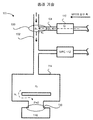
도 1a는 가스 전달 시스템의 부분도의 개략적인 도시를 나타낸다.
도 1b는 캐리어 가스가 흐르는 환경에서 가스의 흐름을 도시한 개략적인 블록 도를 나타낸다.
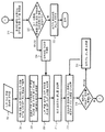
도 2는 발명의 실시형태에서 압력 제어 스킴을 구현하기 위한 단계를 도시한 개략적인 흐름도를 나타낸다.
도 3은 발명의 실시형태에서 수개의 오버슈트 강도를 도시한 개략적인 플롯을 나타낸다.
도 4는 발명의 실시형태에서 오버슈트 공정의 복수의 단계들을 수행하는 단계를 도시하는 개략적인 흐름도를 나타낸다.The invention is illustrated by way of example and not by way of limitation in the figures of the drawings in which like reference numerals refer to like elements.
1A shows a schematic illustration of a partial view of a gas delivery system.
FIG. 1B is a schematic block diagram illustrating the flow of gas in an environment in which carrier gas flows.
FIG. 2 shows a schematic flow diagram illustrating the steps for implementing a pressure control scheme in an embodiment of the invention.
3 shows a schematic plot showing several overshoot intensities in an embodiment of the invention.
4 shows a schematic flow diagram illustrating performing a plurality of steps of an overshoot process in an embodiment of the invention.
본 발명은 첨부된 도면에 도시된 바와 같은 몇몇의 실시 형태들을 참조하여 상세하게 설명될 것이다. 다음의 설명에서, 본 발명의 철저한 이해를 제공하기 위해 많은 구체적 상세들이 설명된다. 그러나 본 발명은 구체적 상세들의 일부 또는 전부를 이용하지 않고도 실시될 수 있다는 것이 당업자에게는 명백할 것이다. 다른 예로, 발명을 불필요하게 모호하게 하지 않기 위해 잘 알려진 공정 단계들 및/또는 구조물들이 자세하게 설명되지 않았다.The invention will be described in detail with reference to some embodiments as shown in the accompanying drawings. In the following description, numerous specific details are set forth in order to provide a thorough understanding of the present invention. However, it will be apparent to those skilled in the art that the present invention may be practiced without using some or all of the specific details. In other instances, well known process steps and / or structures have not been described in detail in order not to unnecessarily obscure the invention.
이하, 방법들과 기술들이 포함된 다양한 실시 형태들이 여기에서 설명된다. 또한, 본 발명은 발명의 기술의 실시 형태를 수행할 수 있는 컴퓨터 판독 가능 명령들이 저장되어 있는, 컴퓨터 판독 가능 매체를 포함하는 제조품을 포함할 수 있다는 것을 명심하여야 한다. 컴퓨터 판독 가능 매체는, 예를 들어, 반도체, 자기, 광자기, 광학 또는 다른 형태의 컴퓨터 판독 가능 코드를 저장하는 컴퓨터 판독 가능 매체를 포함할 수 있다. 나아가, 상기 발명은 또한 발명의 실시 형태들을 실행하기 위한 장치를 포함할 수 있다. 이러한 장치는 본 발명의 실시 형태들에 관련된 작업을 수행하기 위한 전용 및/또는 프로그래밍 가능한 회로를 포함할 수 있다. 이러한 장치의 예들은 일반 범용 컴퓨터 및/또는 적절히 프로그래밍된 전용 컴퓨팅 디바이스를 포함하고, 컴퓨터/컴퓨팅 디바이스와 본 발명의 실시 형태들에 관련된 다양한 작업에 적응된 전용의/프로그램가능한 회로의 조합을 포함할 수 있다.Hereinafter, various embodiments, including methods and techniques, are described herein. It should also be noted that the present invention may include an article of manufacture comprising a computer readable medium having computer readable instructions stored thereon capable of carrying out embodiments of the technology of the invention. Computer-readable media can include, for example, computer-readable media that stores semiconductor, magnetic, magneto-optical, optical or other forms of computer-readable code. Furthermore, the invention may also include an apparatus for carrying out embodiments of the invention. Such an apparatus may include dedicated and / or programmable circuitry for performing tasks related to embodiments of the present invention. Examples of such apparatus include a general purpose computer and / or a suitably programmed dedicated computing device, and may include a combination of a computer / computing device and dedicated / programmable circuitry adapted to various tasks related to embodiments of the present invention. Can be.
상술한 바와 같이, 종래기술에서, 처리 챔버가 평형 압력 상태 (즉, 고정 압력 점) 에 도달한 다음, 하나 이상의 가스 종들이 처리 챔버로 흘러들어갈 때 전달의 지연이 일어날 수 있다. 상이한 가스 종들은 상이한 시간에 챔버에 도달하기 때문에, 가스 조성 드리프트가 일어날 수 있다. 용이한 설명을 위해, 도 1a는 가스 전달 시스템의 부분도의 개략적인 도시를 나타낸다.As noted above, in the prior art, a delay in delivery may occur when one or more gas species flow into the processing chamber after the processing chamber reaches an equilibrium pressure state (ie, a fixed pressure point). Since different gas species arrive at the chamber at different times, gas composition drift can occur. For ease of explanation, FIG. 1A shows a schematic illustration of a partial view of a gas delivery system.
처리 툴 (100) 은 가스를 처리 챔버 (114) 로 전달하는 가스 전달 시스템을 포함할 수 있다. 상기 가스 전달 시스템은 주요 가스라인 (102) (즉, 믹싱 매니폴드) 와 하나 이상의 가스라인 ((104) 와 (106)) 을 포함할 수 있다. 각 가스라인을 통한 가스의 흐름은 MFC (110) 와 MFC (112) 와 같은 유량 제어기 (MFC) 에 의해 제어될 수 있다.The
전형적으로, 상기 처리 챔버 (114) 로의 가스의 흐름은 고압의 가스 혼합물과 저압의 처리 챔버 (114) 와의 압력의 차이에 의해 유도된다. 처리 챔버 (114) 의 압력은 센서에 의해 모니터된다. 센서의 판독에 기초하여, 진공 펌프 (118) 는 진공 펌프 입구에 위치한 쓰로틀 (throttle) 밸브 (130) 를 조정할 수 있다. 쓰로틀 (throttle) 밸브 (130) 의 조정에 의해, 진공 펌프 (118) 는 처리 챔버 (114) 내의 압력을 제어할 수 있다. 쓰로틀 (throttle) 밸브 (130) 의 위치는 처리 챔버 (114) 에서부터 진공 펌프 (118) 까지의 가스 컨덕턴스 (체적 가스 유속) 를 조절하며, 이로써 처리 챔버 (114) 내의 압력을 특정한 평형 압력으로 유지한다. 아래 식 1은 챔버에 있는 소정 가스 종의 부분 압력 (p2) 이 MFC 에 의해 제어되는 가스 흐름 (Q) 과 챔버에서 펌프까지의 컨덕턴스 (k2) 의 비율과 동등한 평형 압력 (pe) 에 도달하는, 평형 상태를 보여준다.Typically, the flow of gas into the

실제로, 쓰로틀 (throttle) 밸브 (130) 의 초기 밸브 위치를 설정하기 위해, 실증적으로 소정의 유속과 압력에서 각각의 가스에 대해 가스 컨덕턴스 곡선이 결정될 수 있다. 처리 챔버 (114) 내의 압력이 설정된 압력 포인트에 도달하면, 기판 처리가 개시될 수 있다.Indeed, in order to set the initial valve position of the

하지만, 상기 챔버 압력이 안정화되어도, 처리 환경은 기판 처리에 이상적이지 못할 수 있다. 이상적으로는, 처리 챔버 (114) 에 도달하기 전에 상이한 가스 종들이 함께 혼합되게 된다. 그러나 처리 챔버 (114) 에 전달된 가스 혼합물은 요구되는 가스 종의 정확한 비율을 가지고 있지 않을 수 있다. 즉, 가스 조성은 처리 챔버 (114) 에서 드리프트 될 수 있다. 상기 식 2는 특정한 시간 (t) 에서의 부분 압력 (p2) 은 가스라인을 통한 가스 흐름 시간 스케일 (τ1) , 처리 챔버에서 펌프까지의 가스 흐름 시간 스케일 (τ2), MFC 가스 유속 (Q), 및 챔버와 펌프 사이의 컨덕턴스 (k2) 에 의존한다는 것을 보여준다.However, even when the chamber pressure is stabilized, the processing environment may not be ideal for substrate processing. Ideally, different gas species will be mixed together before reaching the
일반적인 처리 환경에서, 시간 스케일 (τ2) 와 흐름 컨덕턴스 (k2) 는 모두 주로 처리 챔버의 구조와 펌핑 속도의 함수이기 때문에 변경되지 않는다. 따라서, 시간 t 에서의 부분 압력 (p2) 은 주로 가스라인의 시간 스케일 (τ1) 와 소정 가스의 MFC 유속 (Q) 에 의존한다.In a typical processing environment, the time scale τ 2 and the flow conductance k 2 are both unchanged because they are primarily a function of the structure of the processing chamber and the pumping speed. Thus, the partial pressure p 2 at time t mainly depends on the time scale τ 1 of the gas line and the MFC flow rate Q of the given gas.


가스라인 시간 스케일 (τ1) 는 가스라인 지오메트리에 의해 결정되고 식 3 에서 보여지는 것과 같이, 가스 종의 질량의 제곱근에 반비례한다. 설명의 용이를 위해, 가스의 질량은 인자가 아닌 것으로 가정한다. 예를 들면, 가스라인 (104) 과 가스라인 (106) 을 통해 흐르는 가스는 동일하다. 만약 가스의 질량이 인자가 아닌 경우에, 상기 식 4 에서 보여지는 것과 같이, 가스라인의 시간 스케일 (τ1) 는 가스라인 지오메트리의 인자이다.The gasline time scale τ 1 is inversely proportional to the square root of the mass of the gas species, as determined by the gasline geometry and shown in equation 3. For ease of explanation, it is assumed that the mass of the gas is not a factor. For example, the gas flowing through
상기 식 4에 따르면, 가스라인의 시간 스케일 (τ1) 는 가스라인의 체적 (V1) 과 컨덕턴스 (k1) 의 함수이다. 가스라인의 체적과 흐름 컨덕턴스는 가스라인의 길이 및/또는 지름의 함수이므로, 가스라인의 시간 스케일 (τ1) 는 또한 가스라인의 길이 및/또는 지름의 함수이다. 예를 들어, 가스라인 (106) 이 가스라인 (104) 보다 짧은 길이를 가지고 있다고 가정한다. 위 식 4에 따르면, 가스라인 (104) 의 체적이 가스선 (106) 의 체적보다 더 크고, 가스라인 (104) 의 흐름 컨덕턴스는 가스라인 (106) 보다 작다. 따라서, 가스라인 (104) 의 가스 전달 시간 스케일은 가스라인 (106) 의 가스 전달 시간 스케일보다 더 크다.According to
식 3을 다시 참조하면, 가스라인의 시간 스케일 (τ1) 는 가스라인 지오메트리뿐만 아니라 또한 가스의 분자량의 함수이다. 제조 환경에서, 레시피에 의해 요구되는 가스 종들은 주로 상이한 분자량의 일 수도 있다. 가스의 질량은 특히 저압의 환경에서 중요하다. 저압의 환경에서, 가스 흐름은 분자가 될 수 있다. 다르게 말하면, 가스 흐름은 서로에 독립적 (즉, 가스 분자들간의 운동량 전달이 최소화 됨) 이 될 수 있다. 몇몇의 상이한 가스 종의 레시피에서, 가스의 질량은 가스의 전달 시간을 결정할 수 있다. 동일한 물리적 조건이 주어졌을 때, (예를 들면, 각각의 가스라인이 동일한 가스라인 지오메트리를 가지며, 각 가스 종이 동일한 질량 유속으로 흐르는 등) 무거운 가스 종은 가벼운 가스 종들보다 더 느린 속도로 흐른다. 예를 들어, 수소 (H2) 의 전달 시간은 C4F8 보다 약 3배 더 빠를 것이다. 그 결과로, 가벼운 가스 종들은 무거운 가스 종보다 처리 챔버 내에서 먼저, 평형 압력에 도달한다. 다르게 말하면, 가스 종은 분리될 수 있고 각각의 가스는 상이한 시간에서 평형 상태에 도달하게 된다.Referring back to equation 3, the time scale τ 1 of the gas line is a function of not only the gas line geometry but also the molecular weight of the gas. In the production environment, the gas species required by the recipe may be of primarily different molecular weights. The mass of the gas is especially important in low pressure environments. In low pressure environments, gas flows can be molecular. In other words, the gas flows can be independent of each other (ie, the momentum transfer between gas molecules is minimized). In the recipe of several different gas species, the mass of the gas can determine the delivery time of the gas. Given the same physical conditions, heavy gas species (eg, each gas line has the same gas line geometry, each gas species flows at the same mass flow rate, etc.) flow at a slower rate than light gas species. For example, the delivery time of hydrogen (H 2 ) will be about three times faster than C 4 F 8 . As a result, light gas species reach equilibrium pressures earlier in the processing chamber than heavy gas species. In other words, the gas species can be separated and each gas will reach equilibrium at different times.
이로써 정확한 가스 혼합물이 처리 챔버 (114) 에 전달되지 않더라도 처리 챔버에서 압력 안정화를 이룰 수 있다. 몇몇의 레시피에서는, 적절한 가스 혼합물이 존재하지 않더라도 기판 처리가 시작될 수 있어, 조악한 디바이스가 만들어지는 결과를 초래한다. 다른 레시피에서는, 기판 처리가 적절한 가스 혼합물이 존재할 때까지 지연된다; 그러나, 지연 시간은 긴 공정 시간 때문에 더 높은 제조 비용을 야기한다.This allows for pressure stabilization in the processing chamber even if the correct gas mixture is not delivered to the
처리 환경이 저압의 환경이 아니더라도, 가스 전달은 또한 공정 가스의 압력이 캐리어 가스의 압력에 비해 현저하게 작은 경우에 지연될 수 있다. 도 1b는 캐리어 가스가 흐르는 환경에서 가스의 흐름을 도시하는 개략적인 블록도를 나타낸다. 이러한 예에서, 아르곤과 같은, 캐리어 가스는 공정 가스보다 훨씬 높은 유속으로 주요 가스 전달 라인 (102) (즉, 믹싱 매니폴드) 으로 주입될 수 있다. 캐리어 가스 유도 흐름 환경에서, 공정 가스는 주로 충돌 운동량 전달을 통해 캐리어 가스에 의해 처리 챔버 (114) 로 운반된다. 그러나, 만약 캐리어 가스의 교차지점 (150) (가스라인이 믹싱 매니폴드과 만나는 부분) 에서의 캐리어 가스 압력 (pc) 이 공정 가스 압력 (p1) 보다 높을 때, 상기 공정 가스는 캐리어 가스와 혼합하는 것이 불가능할 수 있다. 그 결과, 상기 공정 가스 압력 (p1) 이 캐리어 가스 압력 (pc) 에 도달할 때까지 상기 공정 가스는 교차지점 (150) 에서 "스턱 (stuck) " 상태가 된다.Even if the processing environment is not a low pressure environment, gas delivery can also be delayed if the pressure of the process gas is significantly smaller than the pressure of the carrier gas. 1B shows a schematic block diagram showing the flow of gas in an environment in which a carrier gas flows. In this example, a carrier gas, such as argon, can be injected into the main gas delivery line 102 (ie, the mixing manifold) at a much higher flow rate than the process gas. In a carrier gas induced flow environment, the process gas is conveyed to the
다르게 말하면, 가스라인 (104) 에 있는 상기 공정 가스는 주요 가스라인 (102) 을 통해 흐르는 캐리어 가스와 혼합하기 전에, 충분한 압력이 가스라인 (예를 들어, 가스라인 (104)) 에서 형성되어야 한다. 몇몇 경우에서, 공정 가스를 캐리어 가스와 혼합할 수 있게 충분한 압력이 형성되기 전에 MFC (110) 에서 가스라인 (104) 으로 공정 가스가 보내지는 동안 아주 긴 지연이 일어날 수 있다. 아래 식 5는 교차지점 (150) 에 형성된 압력을 위해 요구되는 시간 스케일을 나타낸다. 도 5에 보이는 것과 같이, 가스라인 체적이 크고 유속 (Q) 이 작은 경우에 지연시간이 길다.In other words, before the process gas in
![]()
![]()
도 1a 및 도 1b에서 논의된 바와 같이, 저압의 챔버 환경으로 들어가는 공정 가스의 지연은 공정 가스 흐름의 안정화가 설정된 압력 포인트에 도달 되게 한다. 즉, 소정의 가스 종의 가스 전달 시간 스케일은 가스 조성 드리프트를 발생시킬 수 있다. 처리 챔버 내의 지연을 최소화하기 위해 및/또는 평형 압력을 제어하기 위해, 가스라인 컨덕턴스, MFC 유속, 또는 펌프 속도 중 적어도 하나의 파라미터가 변경되어야 한다. 발명의 일 양태에서, 발명자들은 MFC 유속을 짧은 시간 동안 증가시킴으로써, 가스 전달 시간 스케일가 하드웨어의 변경 없이 제어될 수 있다는 것을 깨달았다.As discussed in FIGS. 1A and 1B, the delay of the process gas entering the low pressure chamber environment causes the stabilization of the process gas flow to reach a set pressure point. That is, the gas delivery time scale of a given gas species can cause gas composition drift. In order to minimize delay in the processing chamber and / or to control the equilibrium pressure, at least one parameter of gas line conductance, MFC flow rate, or pump speed must be changed. In one aspect of the invention, the inventors have realized that by increasing the MFC flow rate for a short time, the gas delivery time scale can be controlled without changing hardware.
본 발명의 실시 형태에 따라, 처리 챔버에 가스 전달의 시간 스케일을 줄이기 위해 유량 제어 (MFC) 스킴이 제공된다. 발명의 실시 형태는 실질적인 가스 전달 시간 스케일을 줄이기 위해 MFC의 오버슈팅을 포함한다. 본 발명의 실시 형태는 또한 캐리어 가스가 유도 흐름 환경에서 전달 시간을 줄이기 위해 상기 오버슈팅을 수행하기 위한 복수의 단계들을 포함한다.In accordance with an embodiment of the present invention, a flow control (MFC) scheme is provided to reduce the time scale of gas delivery to the processing chamber. Embodiments of the invention include overshooting the MFC to reduce the substantial gas delivery time scale. Embodiments of the invention also include a plurality of steps for performing said overshooting to reduce the delivery time of carrier gas in an induction flow environment.
발명의 실시 형태에서, 처리 챔버로의 전달 지연을 줄이기 위해 MFC의 오버슈팅을 위한 단일 단계의 오버슈팅 방법이 제공된다. 전달 지연을 최소화하기 위해, 최적의 오버슈트 강도가 결정될 수 있다. 최적의 오버슈트 강도는 처리 챔버 내에서 가스 조성의 드리프트를 최소화하게 하기 위해 MFC 유속을 증가하게 하는 인자이다. 전달 지연을 줄이는 것은 기판 처리의 품질을 향상시키기 때문에, 최적의 오버슈트 강도가 바람직하다. 최적의 오버슈트의 강도를 결정하기 위해, 초기의 오버슈트 강도가 계산될 수 있다. 초기 오버슈트 강도는 오버슈트 기간 및 지연된 가스 종들의 시간 스케일 (τ1) 의 함수이다. 여기서 논의된 것과 같이, 오버슈트 기간은 오버슈트 강도가 MFC 유속에 적용될 수 있는 동안의 경과 시간을 말한다.In an embodiment of the invention, a single step overshooting method for overshooting an MFC is provided to reduce delivery delay to the processing chamber. In order to minimize the propagation delay, the optimal overshoot strength can be determined. Optimal overshoot strength is a factor that increases the MFC flow rate to minimize drift in gas composition in the processing chamber. Since reducing the propagation delay improves the quality of substrate processing, optimal overshoot strength is desirable. To determine the strength of the optimal overshoot, the initial overshoot strength can be calculated. The initial overshoot intensity is a function of the overshoot period and the time scale τ 1 of the delayed gas species. As discussed herein, the overshoot period refers to the elapsed time during which the overshoot strength can be applied to the MFC flow rate.
일 실시 형태에서, 오버슈트 기간은 MFC의 응답시간 (예를 들어, 설정된 명령들에 MFC가 응답할 수 있는 속도) 으로 설정될 수 있다. 일반적인 MFC에서, 응답 지연은 MFC의 설정이 변경될 때 존재할 수 있다. 다르게 말해, MFC의 설정이 변경되는 경우 가스 유속이 변하기 전에 몇 초가 경과할 수 있다. 예를 들어, MFC가 2초의 응답 지연을 가지고 있다고 가정한다. 툴 조작자가 처음으로 MFC를 20 sccm 으로 설정하고 그리고 나서 즉시 MFC의 설정을 10 sccm 으로 변경하면, 가스를 10 sccm 으로 내보내기 전에 MFC는 20 sccm 동안 2초간 가스를 내보낼 수 있다. 지연은 MFC 응답 시간에 의한 것이고 툴 조작자가 고의로 의도한 것이 아니다. 목적은 처리 챔버로의 가스 전달의 시간 스케일을 최소화하기 위한 것이므로, MFC 응답 시간으로 설정된 오버슈트 기간은 총 전달 시간에 아주 작은 시간을 부가할 수도 있고 또는 추가 시간을 부가하지 않을 수 있으며, 이로써 오버슈트 기간을 적용하기 위해 요구되는 시간을 최소화하면서, 오버슈트 강도가 가스 전달의 시간 스케일을 제어하는 방법으로서 채용될 수 있게 된다.In one embodiment, the overshoot period may be set to the response time of the MFC (eg, the rate at which the MFC can respond to set instructions). In a typical MFC, a response delay may exist when the setting of the MFC is changed. In other words, a few seconds may elapse before the gas flow rate is changed when the setting of the MFC is changed. For example, assume that MFC has a response delay of 2 seconds. If the tool operator first sets the MFC to 20 sccm and then immediately changes the setting of the MFC to 10 sccm, the MFC can emit 2 seconds of gas for 20 sccm before exporting the gas to 10 sccm. The delay is due to the MFC response time and is not intentionally intended by the tool operator. Since the purpose is to minimize the time scale of gas delivery to the processing chamber, the overshoot period set by the MFC response time may add very little time to the total delivery time or may not add additional time, thereby over Overshoot intensity can be employed as a method of controlling the time scale of gas delivery, while minimizing the time required to apply the chute period.
앞서 언급한 것들로부터 알 수 있듯이, 응답 시간은 MFC에 대해 특정될 수 있다. 다르게 말해서, 제 1 MFC가 제 2 MFC와 다른 응답을 가지면, 제 1 MFC와 관련된 제 1 가스 종의 초기 오버슈트 강도는 제 2 MFC와 관련된 제 2 가스 종의 초기 오버슈트 강도와 상이할 수도 있다. 따라서, 오버슈트 기간은 MFC 응답 시간에 의해 제한된다.As can be seen from the foregoing, the response time can be specified for MFC. In other words, if the first MFC has a different response than the second MFC, the initial overshoot strength of the first gas species associated with the first MFC may be different from the initial overshoot strength of the second gas species associated with the second MFC. . Thus, the overshoot period is limited by the MFC response time.
앞서 언급한 바와 같이, 오버슈트 강도는 또한 지연된 가스 종들의 시간 스케일 (τ1) 의 함수이다. 시간 스케일 τ1 는 가스라인 지오메트리와 가스의 분자량에 의존하므로, 길이가 긴 가스라인에 대한 처리를 위해서는 오버슈트 강도가 증가되어야 한다. 유사하게, 오버슈트 강도는 무거운 분자량을 가진 가스에 대해 증가되어야 한다.As mentioned above, the overshoot intensity is also a function of the time scale τ 1 of the delayed gas species. Since the time scale τ 1 depends on the gas line geometry and the molecular weight of the gas, the overshoot strength must be increased for processing on long gas lines. Similarly, overshoot strength should be increased for gases with heavy molecular weights.
초기 오버슈트 강도가 결정되었다면, 초기 오버슈트 강도의 인자에 의하여 증가되는 MFC 유속으로 테스트 런이 수행될 수 있다. 예를 들어, 설정된 MFC 유속이 20 sccm 이고 초기 오버슈트 강도가 1.5이면, MFC는 초기에 30 sccm 으로 설정될 것이다. 테스트하는 동안, 챔버 압력 프로파일은 미리 결정된 시간 (예를 들어, 10초) 동안 관측될 수 있다. 챔버 압력 프로파일을 분석함으로써, 초기 오버슈트 강도는 최적의 오버슈트 강도를 식별하기 위해 조정될 수 있다. 일 실시 형태에서, 오버슈트 강도가 미리 정의된 목표 시간 주기 (예를 들어, 2초) 에서의 챔버 압력이 목표 정확도 (예를 들어, 설정된 압력의 1퍼센트) 내에 있는 챔버 압력 프로파일을 생성할 때까지 초기 오버슈트 강도를 조정함으로써 오버슈트 강도가 결정될 수 있다. 안정화된 압력의 환경을 설정하기 위해서는 통상 제한된 시간이 제공되므로, 미리 정의된 목표 시간 주기는 처리 챔버 압력을 안정화시키기 위해 할당된 시간보다 더 적은 시간 주기로 설정하여야 할 것이다.Once the initial overshoot strength has been determined, a test run can be performed with the MFC flow rate increased by the factor of the initial overshoot strength. For example, if the set MFC flow rate is 20 sccm and the initial overshoot intensity is 1.5, the MFC will initially be set to 30 sccm. During the test, the chamber pressure profile can be observed for a predetermined time (eg 10 seconds). By analyzing the chamber pressure profile, the initial overshoot strength can be adjusted to identify the optimal overshoot strength. In one embodiment, when the overshoot intensity produces a chamber pressure profile where the chamber pressure in a predefined target time period (eg, 2 seconds) is within target accuracy (eg, 1 percent of the set pressure). The overshoot strength can be determined by adjusting the initial overshoot strength until. Since a limited time is usually provided to set the environment for a stabilized pressure, the predefined target time period will have to be set to a time period less than the allotted time to stabilize the process chamber pressure.
대안으로 또는 부가적으로, 초기 오버슈트 강도가 MFC 수용력 내에 있지 않은 경우에 오버슈트 기간은 조정될 수 있다. 앞서 언급한 바와 같이, 오버슈트 기간은 오버슈트팅으로 의한 추가적인 시간을 최소화하기 위해 MFC의 응답 시간으로 설정될 수 있다. 그러나, 변경된 MFC 유속 (즉, 오버슈트 강도의 인자에 의해 증가되는 질량 유속) 이 MFC의 최대 유속에 매우 근접하는 경우, 오버슈트 강도를 감소시키기 위해 오버슈트 기간은 증가되어야 한다. 다르게 말해서, 변경된 유량 속도가 미리 결정된 MFC 유속의 최대값의 비율 (95 퍼센트와 같은) 보다 작지 않은 경우, 오버슈트 기간은 변경될 수 있다. 일 실시 형태에서, 미리 결정된 비율은 MFC 내에 존재할 수 있는 잠재적인 하드웨어의 부정확함을 처리하기 위해 100 퍼센트보다 적다. 각각의 MFC는 다른 사양을 가지고 있기 때문에, 최대 MFC 유속은 MFC에 따라 다를 수 있다.Alternatively or additionally, the overshoot period can be adjusted if the initial overshoot strength is not within the MFC capacity. As mentioned above, the overshoot period may be set to the response time of the MFC to minimize additional time due to overshooting. However, if the modified MFC flow rate (ie, mass flow rate increased by the factor of overshoot strength) is very close to the maximum flow rate of the MFC, the overshoot period should be increased to reduce the overshoot strength. In other words, if the changed flow rate is not less than the ratio of the maximum value of the predetermined MFC flow rate (such as 95 percent), the overshoot period can be changed. In one embodiment, the predetermined ratio is less than 100 percent to account for potential hardware inaccuracies that may be present in the MFC. Since each MFC has different specifications, the maximum MFC flow rate may vary depending on the MFC.
일 실시 형태에서, 전달 지연을 일으켰을 수 있는 인자들 및/또는 물리적 조건들 (예를 들어, 가스라인 지오메트리, 가스의 분자량, 가스의 운동량 등) 은 특정 기간 (오버슈트 기간) 에 대해 MFC 유속에 오버슈트를 적용시킴으로써 조정될 수 있다. 따라서, 평형 압력에 도달하기 위한 시간의 가스 종들 간의 차이를 최소화하기 위해 처리 챔버의 가스의 시간 스케일은 조정될 수 있다.In one embodiment, factors and / or physical conditions (eg, gasline geometry, gas molecular weight, gas momentum, etc.) that may have caused delivery delays are dependent upon the MFC flow rate for a particular period (overshoot period). It can be adjusted by applying the overshoot. Thus, the time scale of the gas in the processing chamber can be adjusted to minimize the difference between the gas species in time to reach the equilibrium pressure.
일 실시 형태에서, 캐리어 가스 유도 흐름 환경에서 복수 단계의 오버슈팅 방법이 실시될 수 있다. 캐리어 가스 유도 흐름 환경에서, 단일 단계의 오버슈팅 방법이 전달 지연을 감소시키기 위해 적용될 수 있지만, 복수 단계의 오버슈팅 적용 방법이 전달 지연을 감소시키기 위한 대안의 방법을 제공할 수 있다.In one embodiment, a multi-step overshooting method may be practiced in a carrier gas induced flow environment. In a carrier gas induced flow environment, a single step overshooting method may be applied to reduce the propagation delay, but a multiple step overshoot application method may provide an alternative method for reducing the propagation delay.
앞서 언급한 바와 같이, 캐리어 가스 유도 흐름 환경에서, 낮은 흐름 공정 가스는 이것이 높은 흐름 캐리어 가스와 혼합되기 전에 충분한 압력을 형성하여야 할 수도 있다. 압력의 증가를 가속시키기 위해, 일 실시 형태에서, 저압 흐름 공정 가스의 MFC 유속에 초기 오버슈트가 적용될 수 있다. 일 실시 형태에서, 빌드업 된 오버슈트 기간은 압력 증가 시간과 초기 오버슈트 강도의 비의 함수가 될 수 있다. 제 1 오버슈트 강도 (초기 오버슈트 강도) 가 압력 빌드업 시간 주기를 최소화하기 위해 적용되기 때문에, 일 실시 형태에서, 증가된 오버슈트 기간은 압력 증가 시간보다 짧다. 제어할 수 없는 압력 프로파일 (예를 들어, 스파이킹) 을 방지하기 위해, 일 실시 형태에서, 증가된 오버슈트 기간은 적어도 MFC 응답 시간으로 설정된다. 단일 단계의 오버슈팅 방법과 유사하게, 초기 오버슈트 강도는 오버슈트 기간 및 낮은 흐름 공정 가스의 시간 스케일의 함수가 될 수 있다.As mentioned above, in a carrier gas induced flow environment, the low flow process gas may have to form sufficient pressure before it is mixed with the high flow carrier gas. To accelerate the increase in pressure, in one embodiment, an initial overshoot may be applied to the MFC flow rate of the low pressure flow process gas. In one embodiment, the built up overshoot period may be a function of the ratio of the pressure increase time and the initial overshoot strength. Since the first overshoot strength (initial overshoot strength) is applied to minimize the pressure buildup time period, in one embodiment, the increased overshoot period is shorter than the pressure increase time. In order to prevent an uncontrollable pressure profile (eg spiking), in one embodiment, the increased overshoot period is set to at least MFC response time. Similar to the single step overshoot method, the initial overshoot strength can be a function of the overshoot period and the time scale of the low flow process gas.
낮은 흐름 가스의 압력의 증가를 가속시킨 후, MFC 유속은 어떤 시간 주기 동안 제 2 오버슈트 강도에 의해 변경될 수 있다. 일 실시 형태에서, 제 2 오버슈트 강도에 대한 오버슈트 기간은 MFC 응답 시간으로 설정될 수 있다. 단일 단계의 오버슈팅 방법과 유사하게, 제 2 오버슈트 강도는 실험적으로 결정될 수 있다. 다르게 말해서, 제 2 오버슈트 강도는 최적의 오버슈트 강도가 식별될 때까지 조정될 수 있다.After accelerating the increase in pressure of the low flow gas, the MFC flow rate can be altered by the second overshoot intensity for some period of time. In one embodiment, the overshoot period for the second overshoot strength may be set to the MFC response time. Similar to the single step overshoot method, the second overshoot strength can be determined experimentally. In other words, the second overshoot strength may be adjusted until the optimum overshoot strength is identified.
따라서, 다단계의 오버슈팅 방법은 가스 종들 사이의 유속의 차이에 의해 존재할 수 없는 상이한 처리 환경에 맞추기 위해 복수의 오버슈트 강도를 적용하는 것을 가능하게 한다. 단일 단계의 오버슈팅 방법과 유사하게, 다단계의 오버슈팅 방법은 오버슈트 스킴의 적용을 위한 요구 시간을 최소화하면서 더 빠른 가스 전달을 가능하게 한다.Thus, the multistage overshooting method makes it possible to apply a plurality of overshoot intensities to suit different processing environments that cannot exist due to differences in flow rates between gas species. Similar to the single step overshoot method, the multi step overshoot method allows for faster gas delivery while minimizing the time required for the application of the overshoot scheme.
본 발명의 특징과 장점은 도면과 다음의 설명을 참고하면 더 잘 이해될 수 있다.The features and advantages of the present invention may be better understood with reference to the drawings and the following description.
도 2는 발명의 일 실시 형태에서, 압력 제어 스킴을 구현하기 위한 단계들을 도시한 개략적인 흐름도이다.2 is a schematic flowchart illustrating steps for implementing a pressure control scheme in one embodiment of the invention.
제 1 단계 (202) 에서, 느린 가스의 전달 상황이 식별된다. 느린 가스 전달은 많은 이유에 의한 것일 수 있다. 예를 들어, 가스 종들이 처리 챔버 내에서 상이한 시간에 평형 상태에 도달하게 되는 가스 조성 드리프트라고 알려진 상태에 의한 것일 수 있다. 앞서 언급한 바와 같이, 가스 조성 드리프트는 저압 환경 및/또는 캐리어 가스 유도 흐름 환경에서 발생할 수 있다. 당업자는 언제 그 상황이 발생할지를 식별하기 위한 다른 기술들을 가지고 있을 수 있다.In a
일 방법은 압력 시간 프로파일을 측정하는 것을 포함한다. 처리 챔버 내에 위치한 계측 툴을 채용함으로써, 각각의 가스에 대해 처리 챔버 내의 압력이 측정될 수 있다. 가스 종들이 설정된 압력 포인트에 도달할 때까지의 시간 주기가 다른 가스 종들보다 더 오래 걸리는 경우, 가스 구성성분의 드리프트가 발생할 수 있다.One method includes measuring the pressure time profile. By employing a metrology tool located in the processing chamber, the pressure in the processing chamber can be measured for each gas. If the time period until the gas species reaches a set pressure point takes longer than other gas species, drift of the gas component may occur.
캐리어 가스유도 흐름 환경에서의 가스 조성 드리프트는 플라즈마 툴의 구성을 관찰함으로써 또한 식별할 수 있다. 일부의 플라즈마 툴은 공정 가스의 가스라인의 하류에 위치한 캐리어 가스의 가스라인을 가질 수 있다. 캐리어 가스는 하류에 위치하므로, 공정 가스가 캐리어 가스의 압력에 도달할 수 없다면 캐리어 가스는 공정 가스를 처리 챔버의 하류로 운반할 수 없다.Gas composition drift in a carrier gas induced flow environment can also be identified by observing the configuration of the plasma tool. Some plasma tools may have a gas line of carrier gas located downstream of the gas line of process gas. Since the carrier gas is located downstream, the carrier gas cannot carry the process gas downstream of the processing chamber if the process gas cannot reach the pressure of the carrier gas.
또한, 가스 조성 드리프트는 가스라인 구성에 의해 발생할 수 있다. 긴 가스라인은 가스 전달 시간을 부가할 수 있다. 추가적으로, 가스 종들이 상이한 질량들로 구성되어 있다면, 종래 기술은 무거운 가스가 가벼운 가스보다 더 저속으로 흐르는 경향이 있기 때문에 무거운 가스가 처리 챔버 내의 평형 상태에 더 천천히 도달하게 되는 것을 보여준다. 부가적으로 또는 대안으로, 가스라인 구성은 공정 가스가 충분한 압력을 형성하여, 주로 높은 유속으로 흐르고 있는 캐리어 가스와 적절히 혼합하기 위해 가스라인 체적 내에서 다수의 공정 가스 분자를 축적하는 것이 요구된다. 따라서, 소정의 가스 종들에 대해서, 가스라인의 길이가 길 수록 전달 지연이 커질 수 있다.In addition, gas composition drift may occur due to the gas line configuration. Long gas lines can add gas delivery time. In addition, if the gas species are composed of different masses, the prior art shows that heavy gases reach equilibrium in the processing chamber more slowly because heavy gases tend to flow at lower speeds than light gases. Additionally or alternatively, the gasline configuration requires that the process gas create a sufficient pressure to accumulate a large number of process gas molecules within the gasline volume in order to properly mix with the carrier gas which is mainly flowing at high flow rates. Thus, for certain gas species, the longer the gas line, the greater the propagation delay.
다음 단계 (204) 에서, 목표 전달 시간 보다 더 느린 전달 시간을 가진 가스 종들이 식별된다. 목표 전달 시간이 주로 레시피에 특정되지만, 목표 전달 시간이 10 초보다 짧다는 것은 흔하지 않은 것이 아니다. 예를 들어, 느린 전달 시간을 가질 수 있는 가스 종들 세트를 식별하기 위해 부분 압력 프로파일들의 세트가 분석될 수 있다.In a
다음 단계 (206) 에서, 설정된 압력 포인트 (즉, 평형 압력) 에서 소정의 가스 종들에 대해 MFC 유속 (Q) 이 결정될 수 있다. 실시 형태에서, MFC 유속은 컨덕턴스 곡선을 참조하여 결정될 수 있다. 가스 종들의 컨덕턴스 곡선은 소정의 유속의 챔버 압력을 측정함으로써 결정될 수 있다. 당업자는 소정의 설정된 압력에서 소정의 가스 종들의 유속은 이미 측정되어있고 쉽게 얻어질 수 있다는 것을 알 수 있다. 컨덕턴스 곡선 및/또는 유속 도표로부터, 느린 전달 시간을 가질 수 있는 각각의 가스 종들에 대해 소정 압력에서의 유속이 결정될 수 있다.In a
다음 단계 (208) 에서, 느린 전달 가스로서 식별된 각각의 가스 종들의 시간 스케일 (τ1 ) 가 계산된다. 시간 스케일 (τ1 ) 을 계산하는 하나의 방법은 고정된 쓰로틀 (throttle) 밸브 위치를 고정시킨 상태에서의 소정 MFC 유속 (Q) (즉, 일정한 펌프 속력) 에서 처리 챔버 내의 압력의 증가를 추적하는 것이다.In a
다음 단계 (210) 에서, 오버슈트 강도 (α) 는 초기에 특정한 MFC 에서 특정한 가스 종들에 대해 설정될 수 있다. 실시 형태에서, 초기 오버슈트 강도 (α) 는 아래의 식 6을 채용함으로써 설정될 수 있다.In the

위의 식 6에 의하면, 오버슈트 강도 (α) 는 오버슈트 기간 (t0) 및 지연된 기체 종들의 시간 스케일 (τ1 ) 의 함수이다. 일 실시 형태에서, 가스 종들의 오버슈트 기간 (t0) 은 가스 유속을 제어하는 MFC에 의존하는 것일 수 있다. 일반적으로, MFC는 지연된 응답시간을 가질 수 있다. 실시예에서, MFC 제어는 유속 40 sccm 으로 바뀔 수 있다. MFC가 새로운 유속으로 가스를 흐르게 시작하기 전에 처리 툴은 몇 초의 지연을 경험한다. 전형적으로, 지연은 약 0.5에서 2 초이다; 그러나 지연은 특정한 MFC에 따라 다를 수 있다. 따라서, 오버슈트 기간 (t0) 은 MFC의 사양에 따라 달라질 수 있다.According to
다른 실시 형태에서, 오버슈트 기간 (t0) 은 지연된 가스 종들의 시간 스케일 (τ1 ) 에 따라 다를 수 있다. 앞서 언급한 바와 같이, 가스 종들의 시간 스케일 (τ1 ) 는 가스라인 지오메트리 및 가스 종들의 질량에 의존할 수 있다. 캐리어 가스 유도 흐름 환경에서, 가스 종들의 시간 스케일 (τ1 ) 는 또한 캐리어 가스의 유속에 의존할 수 있다. 캐리어 가스는 보통 공정 가스보다 주로 더 빠른 속도로 흐르기 때문에, 공정 가스는 캐리어 가스와 성공적으로 혼합할 수 있기 전에 충분한 압력을 형성하여야 한다. 따라서 추가적인 지연 시간은 위 식 5에서 이미 논한 바와 같이 공정 가스가 충분한 압력을 가지는데 요구되는 시간이다.In another embodiment, the overshoot period t 0 may depend on the time scale τ 1 of the delayed gas species. As mentioned above, the time scale τ 1 of the gas species may depend on the gasline geometry and the mass of the gas species. In a carrier gas induced flow environment, the time scale τ 1 of gas species may also depend on the flow rate of the carrier gas. Since the carrier gas usually flows at a much higher rate than the process gas, the process gas must create sufficient pressure before it can successfully mix with the carrier gas. Therefore, the additional delay time is the time required for the process gas to have sufficient pressure, as already discussed in equation 5 above.
다음 단계 (212) 에서, 초기 오버슈트 강도 (α) 로 유속 (Q) 을 변경함으로써 테스트 런이 수행될 수 있다. 테스트 런이 수행되는 동안. 처리 챔버 내의 가스 조성이 측정될 수 있다.In the
다음 단계 (214) 에서, 오버슈트 강도 (α) 가 충분한지 여부에 대한 결정이 내려진다. 일 실시 형태에서, 미리 결정된 시간 (예를 들어, 10초) 동안 처리 챔버 내에서 가스의 압력 프로파일을 추적하는 것으로 결정이 내려질 수 있다.In the
미리 결정된 목표 시간 주기에서 압력 프로파일에 나타낸 바와 같은 압력이 평형 압력의 목표 정확도 내에 있다면, 오버슈트 강도 (α) 는 가스의 전달 지연을 최소화하는 데에 충분하거나 최적인 것일 수 있다. 안정된 압력 환경을 설정하기 위해서 제한된 시간이 주로 제공되기 때문에, 미리 결정된 목표 시간은 처리 챔버의 압력을 안정화시키기 위해 할당된 시간보다 적게 설정되어야 한다.If the pressure as indicated in the pressure profile in the predetermined target time period is within the target accuracy of the equilibrium pressure, the overshoot intensity α may be sufficient or optimal to minimize the delivery delay of the gas. Since a limited time is mainly provided to establish a stable pressure environment, the predetermined target time should be set less than the time allotted to stabilize the pressure in the processing chamber.
도 3은, 본 발명의 일 실시 형태에서, 수개의 오버슈트 강도 (α) 를 도시하는 개략적인 플롯을 나타낸다. 예를 들어, 평형 압력이 1.00로 설정되어있는 상황을 생각해보자. 실시 형태에서, 챔버 압력이 미리 결정된 목표 시간에서 목표 정확도 (즉, 1 퍼센트) 내에 있다면 오버슈트 강도 (α) 는 최적의 것으로 간주된다. 이 예에서, 오버슈트 기간이 1 초이고 미리 결정된 목표 시간이 오버슈트 기간의 2배 (즉, 2 초) 라고 가정한다. 도면에서 보여지는 것과 같이, 압력이 목표 시간 (2 초) 에서 목표 정확도 내의 고정 압력 (1.00) 에 도달하므로 오버슈트 강도 (α) 2.52 (곡선 (302)) 는 최적의 것으로 간주될 수 있다. 그 결과, 가스의 압력 프로파일이 설정된 압력 포인트에 가까이 근접하고 가스의 압력 프로파일이 미리 결정된 시간 전에 평형 상태에 도달하게 되는 목표 압력 정확도가 설정된다.FIG. 3 shows a schematic plot showing several overshoot intensities α in one embodiment of the invention. For example, consider a situation where the equilibrium pressure is set to 1.00. In an embodiment, the overshoot intensity α is considered optimal if the chamber pressure is within target accuracy (ie 1 percent) at a predetermined target time. In this example, assume that the overshoot period is 1 second and the predetermined target time is twice the overshoot period (ie, 2 seconds). As shown in the figure, the overshoot intensity α 2.52 (curve 302) can be considered optimal since the pressure reaches a fixed pressure 1.00 within the target accuracy at the target time (2 seconds). As a result, a target pressure accuracy is set such that the pressure profile of the gas is close to the set pressure point and the pressure profile of the gas reaches an equilibrium state before a predetermined time.
곡선 (304 및 306) 에서와 같이, 최적의 오버슈트 강도 (α) 가 식별되지 않았다면, 다음 단계 (216) 에서, 아래 식 7에서 보여지는 것과 같이, 오버슈트 강도 (α) 에 의해 얻어진 목표 평형 압력 (pe) 및 시간 t0 에서 압력 (p) 에 대하여, 오버슈트 강도 (α) 가 조정될 수 있다. 단계 (212) 에서 (216) 까지는 반복되는 것이고 최적의 오버슈트 강도가 결정되기 전까지 반복될 수 있다.If the optimal overshoot intensity α is not identified, as in
![]()
![]()
오버슈트 강도 (α) 가 찾아지면, 다음 단계 (218) 에서, 최적의 MFC 오버슈트 강도 (α*) 와 함께 가스가 다시 작동된다.Once the overshoot strength α is found, in the
비록 최적의 오버슈트 강도가 결정될 수 있지만, 최적의 오버슈트 강도가 MFC 유속을 너무 크게 설정하게 되면 부정확함이 발생할 수 있다. 이상적으로, 하드웨어 (예를 들어, MFC) 는 고장 없이 수행될 수 있다. 당업자는 대부분의 하드웨어는 극단적인 범위 (예를 들어, 최대값과 최소값) 에서 수행되도록 설계되지 않을 수 있다는 것을 안다. MFC 내에 존재할 수 있는 잠재적인 오류를 설명하기 위해, 원하는 변경 MFC 유속은 최대 MFC 유속 보다 작을 수 있다. 다음 단계 (220) 에서, 느린 가스 전달 상황이 하드웨어 부정확을 경험하지 않고 해결되었는지에 대한 결정이 내려진다. 분석을 수행하는 일 방법은 변경된 MFC 유속 (즉, Q ×α* ) 이 미리 결정된 최대 MFC 유속의 비율 (예를 들어, 95 퍼센트) 보다 작은지 계산하는 것이다. 실시 형태에서, 미리 결정된 비율은 100 퍼센트보다 더 낮게 설정된다. 최대 MFC 유속은 MFC 사양에 따라 달라지므로, 수용할 수 있는 범위는 실제 상수 대신에 최대 MFC 유속 비율로서 설정된다.Although the optimal overshoot strength can be determined, inaccuracies can occur if the optimal overshoot strength sets the MFC flow rate too large. Ideally, the hardware (eg MFC) can be performed without failure. One skilled in the art knows that most hardware may not be designed to perform in extreme ranges (eg, maximum and minimum values). To account for potential errors that may exist within the MFC, the desired altered MFC flow rate may be less than the maximum MFC flow rate. In a
이 조건이 만족되면, 특정 레시피에 대하여 가스 종들의 최적의 오버슈트 강도 (α* ) 가 식별된다 (단계 (222)).If this condition is met, the optimal overshoot intensity (α *) of the gas species for the particular recipe is identified (step 222).
그러나 이러한 조건이 만족되지 않으면, 다음 단계 (224) 에서, 오버슈트 기간 (t0) 이 증가될 수 있다. 앞서 말한 바와 같이, 처리 챔버로 가스를 전달하는 시간을 증가시킬 가능성을 최소화하기 위해 오버슈트 기간은 MFC 응답 시간에 맞추어 진다. 그러나 변경된 MFC 유속이 MFC의 최대 유속에 너무 근접한 경우, 하드웨어가 부정확할 가능성이 존재할 수 있다. 하드웨어의 제한에 따른 부정확의 가능성을 최소화하기 위해, 실시 형태에서, 최적의 오버슈트 강도를 줄이기 위해 오버슈트 기간은 증가해야 할 수 있고, 그렇게 함으로써 변경된 MFC 유속이 줄어든다.However, if this condition is not satisfied, then in the
단계 (208) 에서 (224) 까지는 최적의 오버슈트 강도가 결정될 때까지 반복될 수 있다.
도 2에서 알 수 있는 것과 같이, 최적의 오버슈트 강도 (α*) 는 특정한 가스에 대해 결정될 수 있다. 최적의 오버슈트 강도 (α*) 를 식별함으로써, 전달 지연은 상당히 줄어들 수 있다. 따라서, 최적의 오버슈트 강도 (α*) 는 하나 이상의 가스 종의 MFC 유속을 조작함으로써 가스 조성 드리프트를 최소화하는데에 이용될 수 있다.As can be seen in FIG. 2, the optimum overshoot strength α * can be determined for a particular gas. By identifying the optimal overshoot intensity α *, the propagation delay can be significantly reduced. Thus, the optimum overshoot strength [alpha] * can be used to minimize gas composition drift by manipulating the MFC flow rates of one or more gas species.
캐리어 가스 유도 흐름에 대해, 도 2에서 설명된 방법은 가스와 관련된 시간 스케일을 감소시킬 수 있다. 그러나 증가된 압력과 관련된 시간 스케일 (tc) 에 의해 발생할 수 있는 추가적인 시간 지연에 의해, 도 2에 설명된 방법은 지연 시간을 더욱 줄일 수 있는 다단계의 오버슈팅 공정을 허용하도록 조정된다. 도 4는, 실시 형태에서, 다단계의 오버슈팅 공정을 수행하기 위한 단계들을 도시하는 개략적인 흐름도를 나타낸다. 예를 들어, 느린 전달 시간을 가진 가스가 캐리어 가스가 흐르는 환경에서 발견되는 상황을 고려한다. For the carrier gas induced flow, the method described in FIG. 2 can reduce the time scale associated with the gas. However, with the additional time delays that may be caused by the time scale t c associated with the increased pressure, the method described in FIG. 4 shows, in an embodiment, a schematic flow diagram illustrating the steps for performing a multi-step overshooting process. For example, consider a situation where a gas with a slow delivery time is found in an environment in which a carrier gas flows.
처음 단계 (402) 에서, 초기 오버슈트 강도 (α) 가 결정된다. 앞서 말한 바와 같이, 캐리어 가스 유도 흐름 환경에서, 가스라인 지오메트리 및/또는 가스 분자량에 의해 발생된 전달 지연뿐만 아니라, 낮은 흐름 공정 가스의 전달 지연도 또한 낮은 흐름 가스가 높은 흐름 캐리어 가스와 혼합하기 위해 충분한 압력을 형성하는데 요구되는 시간 스케일에 의존할 수 있다. 이러한 형태의 전달을 다루기 위해, 실시 형태에서, 제 1 오버슈트 강도는 최대 MFC 유속으로 설정될 수 있다.In the
다음 단계 (404) 에서, 제 1 오버슈트 기간이 계산된다. 실시 형태에서, 제 1 오버슈트 기간 (즉, 증가 오버슈트 기간) 은 압력 증가 시간과 초기 오버슈트 강도의 비의 함수가 될 수 있다. 실시 형태에서, 초기 오버슈트 강도가 증가 시간을 최소화시키도록 증가 오버슈트 강도가 적용되었기 때문에 증가 오버슈트 기간은 증가 시간 보다 짧다. 제 1 오버슈팅 단계의 오버슈트 기간은 아래 식 8을 이용하여 계산될 수 있다. 실시 형태에서 제어되지 않은 압력 프로파일 (예를 들어, 스파이킹) 을 최소화하기 위해 제 1 오버슈트 기간 (txa) 은 MFC 응답 시간 (t0) 보다 더 크거나 같은 값으로 설정될 수 있다.In a

낮은 흐름 공정 가스의 압력 증가가 가속화된 후, MFC 유속은 가스라인 지오메트리 및/또는 가스의 분자량과 관련된 시간 스케일을 관리하기 위해 변경될 수 있다. 다음 단계 (406) 에서, 제 2 오버슈트 기간은 단일 단계의 오버슈팅과 유사하게 결정된다. 제 2 오버슈트 기간은 가스라인 지오메트리의 분자량과 관련된 시간 스케일와 관련된 시간을 관리하기 위해 요구되는 시간이기 때문에, 제 2 오버슈트 기간은, 실시 형태에서, 총 압력 안정화 시간에 부가되는 추가적인 시간을 최소화하기 위해 (도 2의 오버슈트 기간과 같은) MFC 응답 시간으로 설정될 수 있다.After the pressure increase in the low flow process gas is accelerated, the MFC flow rate can be altered to manage the gas line geometry and / or the time scale associated with the molecular weight of the gas. In the
제 2 오버슈트 기간이 결정된 후, 다음 단계 (408) 에서, 제 2 오버슈트 강도가 결정된다. 실시 형태에서, 제 2 오버슈트 강도는 테스트 런의 수행에 의해 결정될 수 있다. 실시 형태에서, 테스트 런은 초기 오버슈트 강도 (즉, 제 1 오버슈트 강도) 로 MFC 유속 (Q) 을 증가시키는 것을 포함할 수 있다. 단일 단계의 오버슈팅 방법과 유사하게, 제 1 오버슈트 강도는 실험적으로 결정될 수 있다. 예를 들어, 제 2 오버슈트 강도는 최적의 오버슈트 강도 (α*) 가 (미리 정의된 목표 시간에 있는 챔버 압력이 챔버 압력의 목표 정확도 내에 있는 것과 같이) 확인될 때까지 조정될 수 있다. 단계 (406) 은 도 2의 단계 (212) 내지 단계 (216) 과 유사하다.After the second overshoot period is determined, in a
제 2 오버슈트 강도가 결정되면, 그 다음 단계 (410) 인 다른 테스트 런이 수행될 수 있다. 이 테스트 런은, 일 실시 형태에서, 복수의 오버슈트 강도와 오버슈트 기간을 포함할 수 있다.Once the second overshoot strength is determined, another test run may then be performed,
다음 단계 (412) 에서, 느린 가스 전달 상황이 해결되었는지 여부에 대한 결정이 내려진다. 도 2에서와 같이, 제 1 오버슈트 기간 및 제 2 오버슈트 기간에 대해 변경된 MFC 유속이 미리 결정된 최대 MFC 유속의 비율 내에 있는지 여부를 결정함으로써 결정이 내려진다.In a
조건이 만족되면, 특정 레시피의 가스 종들에 대해 최적의 오버슈트 강도 (α*) 가 식별되고 (단계 (414)) 프로세스는 종료할 수 있다.If the condition is met, the optimal overshoot intensity [alpha] * is identified for the gas species of the particular recipe (step 414) and the process can end.
그러나 조건이 만족되지 않으면, 단계 (416) 에서, 제 2 오버슈트 기간이 변경될 수 있다.However, if the condition is not satisfied, at
단계 (406) 내지 단계 (415) 은 최적의 MFC 스킴이 결정되기 전까지 반복될 수 있다.
따라서, 다단계의 오버슈팅 방법은 총 가스 전달 시간에 영향을 미칠 수 있는 다른 시간 스케일들을 설정하기 위해 복수의 오버슈트 강도를 적용하는 것을 가능하게 한다. 단일 단계의 오버슈팅 방법과 유사하게, 다단계의 오버슈팅 방법은 오버슈트 강도를 적용하기 위해 요구되는 시간을 최소화하면서 전달 시간을 감소시키는 수정된 MFC 유속을 결정하는 방법을 제공한다. 도 2 및 도 4에서 설명된 방법은 기술자에 의해 수동으로 수행될 수 있다. 도 2 및 4에 의도된 바와 같은 실시 형태에서, MFC 스킴은, 또한 자동으로 적용될 수 있어 (예를 들어, 소프트웨어 애플리케이션), 노동 비용을 줄이고 사람에 의한 오차의 위험을 최소화할 수 있다.Thus, the multi-step overshooting method makes it possible to apply a plurality of overshoot intensities to set different time scales that may affect the total gas delivery time. Similar to the single step overshoot method, the multi step overshoot method provides a method of determining a modified MFC flow rate that reduces the transfer time while minimizing the time required to apply the overshoot strength. The method described in FIGS. 2 and 4 can be performed manually by a technician. In the embodiment as intended in FIGS. 2 and 4, the MFC scheme can also be applied automatically (eg, a software application), thereby reducing labor costs and minimizing the risk of human error.
본 발명의 하나 이상의 실시 형태에서 알 수 있듯이, 방법들은 가스 종들의 시간 스케일을 관리하기 위해 공급된다. 최적의 오버슈트 강도를 결정함으로써, MFC 유속은 가스 조성 드리프트를 상당히 감소시키도록 조정될 수 있다. 수정된 MFC 유속으로, 가스 처리량의 보다 양호한 제어가 제공됨으로써 덜 조악한 기판이 제조되게 된다. 따라서, 오버슈팅 방법은 전체 프로세싱 시간에서 아주 작은 증가 또는 증가 없이 높은 품질의 기판을 제조하기 위한 저가의 해결책을 제공한다.As can be seen in one or more embodiments of the present invention, methods are provided to manage the time scale of gas species. By determining the optimum overshoot strength, the MFC flow rate can be adjusted to significantly reduce gas composition drift. With a modified MFC flow rate, better control of gas throughput is provided, resulting in less coarse substrates. Thus, the overshooting method provides a low cost solution for producing high quality substrates without a slight increase or increase in overall processing time.
본 발명이 몇몇의 바람직한 실시 형태들에 의해 설명되었지만, 본 발명의 범위 내에 포함되는 변경, 치환, 및 등가물이 있을 수 있다. 본 명세서에서 다양한 예들이 제공되었지만, 이러한 예들은 실례가 되는 것이고 본 발명에 대하여 제한하는 것이 아닌 것으로 의도되었다.Although the present invention has been described by some preferred embodiments, there may be variations, substitutions, and equivalents included within the scope of the present invention. While various examples have been provided herein, these examples are intended to be illustrative and are not intended to be limiting of the invention.
비록 여기에 제공된 명칭과 요약은 편의를 위한 것이고 청구항의 범위를 해석하기 위해 사용되어서는 안 된다. 나아가, 요약서는 고도로 단축된 형식으로 쓰여졌고 편의를 위해 제공된 것이므로 청구항에 설명된 전체적인 발명을 설명 또는 제한하기 위해 사용되어서는 안 된다. 용어 "설정" 은 0, 1, 또는 1 보다 큰 수를 포함하는 일반적으로 이해되는 수학적인 의미를 가지는 것으로 의도된다. 또한, 본 발명의 방법들과 장치들을 구현하는 많은 대안의 방식들이 있는 것을 알아야 한다. 따라서 다음의 청구항들은 본 발명의 진정한 사상 및 내에 포함되는 모든 변경, 치환, 및 등가물을 포함하는 것으로 해석되는 것으로 의도되었다.Although the names and summaries provided herein are for convenience only and should not be used to interpret the scope of the claims. Furthermore, the abstract is written in a highly shortened form and is provided for convenience and should not be used to describe or limit the overall invention described in the claims. The term "set" is intended to have a generally understood mathematical meaning including a number of zero, one, or greater than one. It should also be appreciated that there are many alternative ways of implementing the methods and apparatuses of the present invention. Accordingly, the following claims are intended to be construed to include the true spirit and all changes, substitutions, and equivalents included in the present invention.
Claims (20)
상기 MFC 제어 스킴은 플라즈마 처리 시스템의 처리 챔버로의 가스 전달을 위한 시간 스케일을 감소시키도록 구성되고,
상기 MFC 제어 스킴을 확인하는 방법은,
목표 전달 시간 스케일보다 느린 전달 시간 세트를 갖는, 상기 레시피의 실행 중에 이용되는 지연된 가스 종들 세트를 식별하는 단계;
상기 지연된 가스 종들 세트의 각 가스 종에 대해, MFC 유속을 증가하게 하는 인자인 초기 오버슈트 강도를 설정하는 단계;
상기 지연된 가스 종들의 상기 각 가스 종에 대해, 상기 초기 오버슈트 강도를 상기 MFC 유속에 적용했을 때의 기간인 초기 오버슈트 기간을 결정하는 단계; 및
상기 지연된 가스 종들 세트의 상기 각 가스 종에 대한 MFC 하드웨어 조정에 의해 상기 레시피를 실행함으로써 상기 MFC 제어 스킴을 설정하는 단계를 포함하고,
상기 MFC 하드웨어의 조정은, 상기 MFC 제어 스킴이 상기 지연된 가스 종들 세트의 각 가스 종에 대해 상기 처리 챔버에 대한 평형 압력의 목표 정확도 내에서 압력 프로파일을 제공하는지를 결정하기 위해 상기 초기 오버슈트 기간에 상기 초기 오버슈트 강도를 적용하는 것을 포함하는, MFC 제어 스킴 확인 방법.A method of identifying a flow controller (MFC) control scheme for a recipe,
The MFC control scheme is configured to reduce a time scale for gas delivery to a processing chamber of a plasma processing system,
The method of confirming the MFC control scheme is
Identifying a set of delayed gas species used during execution of the recipe having a set of delivery times slower than a target delivery time scale;
For each gas species of the set of delayed gas species, setting an initial overshoot intensity that is a factor that increases the MFC flow rate;
Determining, for each gas species of the delayed gas species, an initial overshoot period which is a period when the initial overshoot intensity is applied to the MFC flow rate; And
Establishing the MFC control scheme by executing the recipe by MFC hardware adjustment for each gas species of the delayed gas species set,
The adjustment of the MFC hardware causes the initial overshoot period to determine whether the MFC control scheme provides a pressure profile within the target accuracy of the equilibrium pressure for the processing chamber for each gas species of the set of delayed gas species. A method of identifying an MFC control scheme, comprising applying an initial overshoot strength.
상기 지연된 가스 종들 세트의 상기 각 가스 종의 MFC 유속을 식별하는 단계; 및
상기 지연된 가스 종들 세트의 상기 각 가스 종의 시간 스케일을 결정하는 단계를 더 포함하고,
상기 시간 스케일은 가스라인 지오메트리 (geometry) , 상기 각 가스 종의 질량, 및 상기 각 가스 종의 상기 MFC 유속 중 적어도 하나의 함수인, MFC 제어 스킴 확인 방법.The method of claim 1,
Identifying an MFC flow rate of each gas species of the delayed gas species set; And
Determining a time scale of each gas species of the delayed gas species set,
And the time scale is a function of at least one of gasline geometry, the mass of each gas species, and the MFC flow rate of each gas species.
상기 초기 오버슈트 기간은,
상기 MFC 하드웨어의 지연된 응답 시간, 및
상기 지연된 가스 종들 세트의 상기 각 가스 종의 시간 스케일 중 적어도 하나의 인자이고,
상기 시간 스케일은 가스라인 지오메트리, 상기 각 가스 종의 질량, 및 상기 각 가스 종의 상기 MFC 유속 중 하나의 함수인, MFC 제어 스킴 확인 방법.The method of claim 1,
The initial overshoot period,
Delayed response time of the MFC hardware, and
Is a factor of at least one of the time scales of each gas species of the set of delayed gas species,
And the time scale is a function of one of gasline geometry, the mass of each gas species, and the MFC flow rate of each gas species.
상기 초기 오버슈트 강도는 상기 초기 오버슈트 기간과 상기 지연된 가스 종들 세트의 상기 각 가스 종의 시간 스케일의 함수이고,
상기 시간 스케일은 가스라인 지오메트리, 상기 가스 종의 질량, 및 상기 각 가스 종의 상기 MFC 유속 중 하나의 함수인, MFC 제어 스킴 확인 방법.The method of claim 1,
The initial overshoot intensity is a function of the initial overshoot period and the time scale of each gas species of the set of delayed gas species,
And the time scale is a function of one of gasline geometry, the mass of the gas species, and the MFC flow rate of each gas species.
상기 지연된 가스 종들 세트의 상기 각 가스 종에 대한 상기 압력 프로파일이 상기 처리 챔버에 대한 상기 평형 압력의 상기 목표 정확도 내에 있지 않은 경우, 상기 초기 오버슈트 강도를 조정하는 단계를 더 포함하는, MFC 제어 스킴 확인 방법.The method of claim 1,
Adjusting the initial overshoot strength if the pressure profile for each gas species of the delayed gas species set is not within the target accuracy of the equilibrium pressure for the processing chamber. checking way.
조정된 MFC 유속이 상기 MFC 하드웨어에 대한 최대 MFC 유속의 미리 결정된 비율보다 더 큰 경우, 상기 지연된 가스 종들 세트의 상기 각 가스 종의 상기 초기 오버슈트 기간이 변경되고,
상기 조정된 MFC 유속은 상기 초기 오버슈트 기간에 대한 상기 초기 오버슈트 강도에 의해 변경된 상기 MFC 유속인, MFC 제어 스킴 확인 방법.The method of claim 5, wherein
If the adjusted MFC flow rate is greater than a predetermined ratio of the maximum MFC flow rate for the MFC hardware, the initial overshoot period of each gas species of the delayed gas species set is changed,
And the adjusted MFC flow rate is the MFC flow rate changed by the initial overshoot intensity for the initial overshoot period.
초기 오버슈트 강도가 상기 평형 압력의 목표 정확도 내에 있고 상기 조정된 MFC 유속이 상기 MFC 하드웨어에 대한 상기 최대 MFC 유속의 미리 결정된 비율보다 작을 때, 상기 지연된 가스 종들 세트의 상기 각 가스 종에 대한 최적의 오버슈트 강도가 결정되는, MFC 제어 스킴 확인 방법.The method of claim 6
When initial overshoot strength is within the target accuracy of the equilibrium pressure and the adjusted MFC flow rate is less than a predetermined ratio of the maximum MFC flow rate to the MFC hardware, the optimum for each gas species of the set of delayed gas species A method of verifying an MFC control scheme, in which overshoot strength is determined.
상기 MFC 제어 스킴은 플라즈마 처리 시스템의 처리 챔버로의 가스 전달을 위한 시간 스케일을 감소시키도록 구성되고,
상기 MFC 제어 스킴을 설정하는 방법은,
목표 전달 시간 스케일보다 느린 전달 시간 세트를 갖는, 상기 레시피의 실행 중에 이용되는 지연된 가스 종들 세트를 식별하는 단계;
상기 지연된 가스 종들 세트의 가스 종에 대해, 초기 오버슈트 강도를 설정하는 단계로서, 상기 초기 오버슈트 강도는 초기 오버슈트 기간 동안 MFC 유속을 증가하게 하는 제 1 인자이고, 상기 초기 오버슈트 기간은 상기 초기 오버슈트 강도를 상기 MFC 유속에 적용하는 제 1 시간 기간인, 상기 초기 오버슈트 강도를 설정하는 단계;
상기 지연된 가스 종들 세트의 상기 각 가스 종의 제 2 오버슈트 강도를 설정하는 단계로서, 상기 제 2 오버슈트 강도는 제 2 오버슈트 기간 동안 상기 MFC 유속을 증가하게 하는 제 2 인자이고, 상기 제 2 오버슈트 기간은 상기 제 2 오버슈트 강도를 상기 MFC 유속에 적용하는 제 2 기간인, 상기 제 2 오버슈트 강도를 설정하는 단계; 및
상기 지연된 가스 종들 세트의 상기 각 가스 종에 대한 MFC 하드웨어 조정에 의해 상기 레시피를 실행함으로써 MFC 제어 스킴을 설정하는 단계를 포함하고,
상기 MFC 하드웨어의 조정은 상기 MFC 제어 스킴이 상기 지연된 가스 종들 세트의 가스 종에 대해 상기 처리 챔버에 대한 형평 압력의 목표 정확도 내에서 압력 프로파일을 제공하는지 결정하기 위해 상기 초기 오버슈트 강도와 상기 제 2 오버슈트 강도를 적용하는 것을 포함하는, MFC 제어 스킴 설정 방법.A method of setting up a flow controller (MFC) control scheme for a recipe,
The MFC control scheme is configured to reduce a time scale for gas delivery to a processing chamber of a plasma processing system,
The method of setting the MFC control scheme,
Identifying a set of delayed gas species used during execution of the recipe having a set of delivery times slower than a target delivery time scale;
For the gas species of the set of delayed gas species, setting an initial overshoot intensity, wherein the initial overshoot intensity is a first factor that increases the MFC flow rate during the initial overshoot period, and the initial overshoot period is Setting the initial overshoot intensity, the first time period of applying an initial overshoot intensity to the MFC flow rate;
Setting a second overshoot intensity of each gas species of the set of delayed gas species, wherein the second overshoot intensity is a second factor that increases the MFC flow rate during a second overshoot period, and wherein the second overshoot intensity Setting the second overshoot intensity, wherein the overshoot period is a second period of applying the second overshoot intensity to the MFC flow rate; And
Establishing an MFC control scheme by executing the recipe by MFC hardware adjustment for each gas species of the delayed gas species set,
The adjustment of the MFC hardware causes the initial overshoot strength and the second to determine if the MFC control scheme provides a pressure profile within the target accuracy of equilibrium pressure for the processing chamber for the gas species of the set of delayed gas species. A method of setting an MFC control scheme, comprising applying overshoot intensity.
상기 지연된 가스 종들 세트의 상기 각 가스 종의 MFC 유속을 식별하는 단계; 및
상기 지연된 가스 종들 세트의 상기 각 가스 종의 시간 스케일을 결정하는 단계를 더 포함하고,
상기 시간 스케일은 가스라인 지오메트리, 상기 각 가스 종의 질량, 및 상기 각 가스 종의 상기 MFC 유속 중 적어도 하나의 함수인, MFC 제어 스킴 설정 방법.The method of claim 8,
Identifying an MFC flow rate of each gas species of the delayed gas species set; And
Determining a time scale of each gas species of the delayed gas species set,
And the time scale is a function of at least one of gasline geometry, the mass of each gas species, and the MFC flow rate of each gas species.
상기 각 가스 종의 상기 초기 오버슈트 강도는 상기 MFC 하드웨어에 대한 최대 MFC 유속으로 설정되는, MFC 제어 스킴 설정 방법.The method of claim 9,
And the initial overshoot strength of each gas species is set to a maximum MFC flow rate for the MFC hardware.
상기 각 가스 종에 대한 상기 초기 오버슈트 기간은 상기 초기 오버슈트 강도와 압력 증가 시간 기간의 인자이고, 상기 압력 증가 시간 기간은, 상기 각 가스 종에 대한 압력이 캐리어 가스에 대한 압력과 적어도 매칭되도록 누적되는 동안의 시간 기간이며, 상기 캐리어 가스는 상기 각 가스 종보다 높은 유속으로 흐르는, MFC 제어 스킴 확인 방법.The method of claim 10,
The initial overshoot period for each gas species is a factor of the initial overshoot strength and pressure increase time period, wherein the pressure increase time period is such that the pressure for each gas species is at least matched to the pressure for a carrier gas. A time period during accumulation, wherein the carrier gas flows at a higher flow rate than the respective gas species.
상기 제 2 오버슈트 기간은 상기 MFC 하드웨어에 대한 지연된 응답 시간의 인자인, MFC 제어 스킴 설정 방법.The method of claim 11,
And the second overshoot period is a factor of a delayed response time for the MFC hardware.
상기 제 2 오버슈트 강도는 초기에 상기 초기 오버슈트 강도로 설정되고, 상기 제 2 오버슈트 강도는 수집된 실험 데이터를 적용하여 조정되며, 상기 지연된 가스 종들 세트의 상기 각 가스 종의 상기 압력 프로파일이 상기 처리 챔버에 대한 상기 평형 압력의 목표 정확도 내에 있지 않은 경우 상기 제 2 오버슈트 강도가 조정되는, MFC 제어 스킴 설정 방법.The method of claim 12,
The second overshoot strength is initially set to the initial overshoot strength, the second overshoot strength is adjusted by applying collected experimental data, and the pressure profile of each gas species of the delayed gas species set is And the second overshoot strength is adjusted when not within the target accuracy of the equilibrium pressure for the processing chamber.
상기 제 2 오버슈트 강도와 상기 제 2 오버슈트 기간에 기초한, 조정된 MFC 유속이 상기 MFC 하드웨어에 대한 상기 최대 MFC 유속의 미리 결정된 비율보다 큰 경우, 상기 지연된 가스 종들 세트의 상기 각 가스 종에 대한 상기 제 2 오버슈트 기간이 변경되는, MFC 제어 스킴 설정 방법.The method of claim 13,
If the adjusted MFC flow rate, based on the second overshoot intensity and the second overshoot period, is greater than a predetermined ratio of the maximum MFC flow rate for the MFC hardware, for the respective gas species of the set of delayed gas species MFC control scheme setting method, wherein the second overshoot period is changed.
상기 제 2 오버슈트 강도가 상기 평형 압력의 목표 정확도 내에 있고 상기 조정된 MFC 유속이 상기 MFC 하드웨어에 대한 상기 최대 MFC 유속의 미리 결정된 비율보다 작을 때, 상기 지연된 가스 종들 세트의 상기 각 가스 종에 대한 상기 최적의 오버슈트 강도가 결정되는, MFC 제어 스킴 설정 방법.The method of claim 14,
For the respective gas species of the set of delayed gas species when the second overshoot intensity is within the target accuracy of the equilibrium pressure and the adjusted MFC flow rate is less than a predetermined ratio of the maximum MFC flow rate for the MFC hardware. And the optimal overshoot strength is determined.
목표 전달 시간 스케일보다 느린 전달 시간 세트를 갖는, 상기 레시피의 상기 실행 중에 이용되는 지연된 가스 종들 세트를 식별하는 단계;
각 가스 종에 대해, 유량 제어기 (MFC) 유속이 증가되게 하는 인자인, 초기 오버슈트 강도를 설정하는 단계;
상기 초기 오버슈트 강도를 상기 각 가스 종의 상기 MFC 유속에 적용하는 시간 기간인 초기 오버슈트 기간을 상기 각 가스 종에 대해 결정하는 단계;
상기 초기 오버슈트 기간에 상기 초기 오버슈트 강도를 적용함으로써 상기 각 가스 종에 대해 조정된 MFC 유속으로 상기 레시피를 실행하는 단계;
상기 초기 오버슈트 강도가 상기 최적 오버슈트 강도인지를 결정하기 위해, 상기 처리 챔버에 대한 평형 압력의 목표 정확도에 대해 상기 레시피의 상기 실행 중에 설정된 상기 각 가스 종에 대한 압력 프로파일을 비교하는 단계; 및
상기 각 가스 종에 대한 상기 압력 프로파일이 상기 처리 챔버에 대한 상기 평형 압력의 상기 목표 정확도 내에 있지 않은 경우, 상기 초기 오버슈트 강도를 조정하는 단계를 포함하는, 최적의 오버슈트 강도 결정 방법.A method of determining an optimal overshoot intensity for reducing gas delivery time to a processing chamber of a plasma processing system during the execution of a recipe,
Identifying a set of delayed gas species used during the execution of the recipe, the set of delivery times being slower than a target delivery time scale;
For each gas species, setting an initial overshoot intensity, a factor causing the flow rate controller (MFC) flow rate to be increased;
Determining an initial overshoot period for each gas species which is a time period for applying the initial overshoot strength to the MFC flow rate of each gas species;
Executing the recipe at an adjusted MFC flow rate for each gas species by applying the initial overshoot strength to the initial overshoot period;
Comparing the pressure profile for each gas species set during the execution of the recipe against a target accuracy of the equilibrium pressure for the processing chamber to determine if the initial overshoot intensity is the optimal overshoot intensity; And
If the pressure profile for each gas species is not within the target accuracy of the equilibrium pressure for the processing chamber, adjusting the initial overshoot strength.
상기 지연된 가스 종들 세트의 상기 각 가스 종에 대한 상기 MFC 유속을 식별하는 단계; 및
상기 지연된 가스 종들 세트의 상기 각 가스 종의 시간 스케일을 결정하는 단계를 더 포함하고,
상기 시간 스케일은 가스라인 지오메트리, 상기 각 가스 종의 질량, 및 상기 각 가스 종의 상기 MFC 유속 중 적어도 하나의 함수인, 최적의 오버슈트 강도 결정 방법.17. The method of claim 16,
Identifying the MFC flow rate for each gas species of the delayed gas species set; And
Determining a time scale of each gas species of the delayed gas species set,
Wherein the time scale is a function of at least one of gasline geometry, the mass of each gas species, and the MFC flow rate of each gas species.
상기 초기 오버슈트 강도는 상기 초기 오버슈트 기간과 상기 지연된 가스 종들 세트의 상기 각 가스 종의 시간 스케일의 함수인, 최적의 오버슈트 강도 결정 방법.The method of claim 17,
Wherein the initial overshoot intensity is a function of the initial overshoot period and the time scale of each gas species of the set of delayed gas species.
상기 조정된 MFC 유속이 MFC 하드웨어에 대한 최대 MFC 유속의 미리 결정된 비율보다 더 큰 경우, 상기 지연된 가스 종들 세트의 상기 각 가스 종에 대한 상기 초기 오버슈트 기간이 변경되는, 최적의 오버슈트 강도 결정 방법.The method of claim 18,
If the adjusted MFC flow rate is greater than a predetermined rate of maximum MFC flow rate for MFC hardware, the initial overshoot period for each gas species of the delayed gas species set is changed. .
상기 최적의 오버슈트 강도가 상기 평형 압력의 목표 정확도 내에 있고 상기 조정된 MFC 유속이 상기 MFC 하드웨어에 대한 상기 최대 MFC 유속의 미리 결정된 비율보다 작을 때, 상기 지연된 가스 종들 세트의 상기 각 가스 종에 대한 상기 최적의 오버슈트 강도가 결정되는, 최적의 오버슈트 강도 결정 방법.The method of claim 19,
For the respective gas species of the set of delayed gas species when the optimal overshoot strength is within the target accuracy of the equilibrium pressure and the adjusted MFC flow rate is less than a predetermined ratio of the maximum MFC flow rate for the MFC hardware. Wherein the optimum overshoot strength is determined.
Applications Claiming Priority (4)
| Application Number | Priority Date | Filing Date | Title |
|---|---|---|---|
| US7453908P | 2008-06-20 | 2008-06-20 | |
| US61/074,539 | 2008-06-20 | ||
| US12/477,196 | 2009-06-03 | ||
| US12/477,196 US8340827B2 (en) | 2008-06-20 | 2009-06-03 | Methods for controlling time scale of gas delivery into a processing chamber |
Publications (1)
| Publication Number | Publication Date |
|---|---|
| KR20110019376A true KR20110019376A (en) | 2011-02-25 |
Family
ID=41432039
Family Applications (1)
| Application Number | Title | Priority Date | Filing Date |
|---|---|---|---|
| KR1020107028548A KR20110019376A (en) | 2008-06-20 | 2009-06-12 | Methods for controlling time scale of gas delivery into a processing chamber |
Country Status (6)
| Country | Link |
|---|---|
| US (1) | US8340827B2 (en) |
| JP (1) | JP2011524948A (en) |
| KR (1) | KR20110019376A (en) |
| CN (1) | CN102067280B (en) |
| TW (1) | TWI477938B (en) |
| WO (1) | WO2009155221A2 (en) |
Families Citing this family (23)
| Publication number | Priority date | Publication date | Assignee | Title |
|---|---|---|---|---|
| JP5346628B2 (en) * | 2009-03-11 | 2013-11-20 | 株式会社堀場エステック | Mass flow controller verification system, verification method, verification program |
| US8770215B1 (en) * | 2011-07-20 | 2014-07-08 | Daniel T. Mudd | Low flow injector to deliver a low flow of gas to a remote location |
| US9690301B2 (en) | 2012-09-10 | 2017-06-27 | Reno Technologies, Inc. | Pressure based mass flow controller |
| US9958302B2 (en) | 2011-08-20 | 2018-05-01 | Reno Technologies, Inc. | Flow control system, method, and apparatus |
| US9188989B1 (en) | 2011-08-20 | 2015-11-17 | Daniel T. Mudd | Flow node to deliver process gas using a remote pressure measurement device |
| DE102013109210A1 (en) * | 2013-08-20 | 2015-02-26 | Aixtron Se | Evacuable chamber, in particular with a purge gas flushable loading sluice |
| US9580360B2 (en) | 2014-04-07 | 2017-02-28 | Lam Research Corporation | Monolithic ceramic component of gas delivery system and method of making and use thereof |
| TWI693638B (en) | 2014-04-07 | 2020-05-11 | 美商蘭姆研究公司 | Configuration independent gas delivery system |
| US10557197B2 (en) | 2014-10-17 | 2020-02-11 | Lam Research Corporation | Monolithic gas distribution manifold and various construction techniques and use cases therefor |
| US10022689B2 (en) | 2015-07-24 | 2018-07-17 | Lam Research Corporation | Fluid mixing hub for semiconductor processing tool |
| US10118263B2 (en) | 2015-09-02 | 2018-11-06 | Lam Researech Corporation | Monolithic manifold mask and substrate concepts |
| US10215317B2 (en) | 2016-01-15 | 2019-02-26 | Lam Research Corporation | Additively manufactured gas distribution manifold |
| US9879795B2 (en) | 2016-01-15 | 2018-01-30 | Lam Research Corporation | Additively manufactured gas distribution manifold |
| US10453721B2 (en) | 2016-03-15 | 2019-10-22 | Applied Materials, Inc. | Methods and assemblies for gas flow ratio control |
| US10303189B2 (en) | 2016-06-30 | 2019-05-28 | Reno Technologies, Inc. | Flow control system, method, and apparatus |
| US11144075B2 (en) | 2016-06-30 | 2021-10-12 | Ichor Systems, Inc. | Flow control system, method, and apparatus |
| US10838437B2 (en) | 2018-02-22 | 2020-11-17 | Ichor Systems, Inc. | Apparatus for splitting flow of process gas and method of operating same |
| US10679880B2 (en) | 2016-09-27 | 2020-06-09 | Ichor Systems, Inc. | Method of achieving improved transient response in apparatus for controlling flow and system for accomplishing same |
| JP6762218B2 (en) * | 2016-12-13 | 2020-09-30 | 株式会社堀場エステック | Flow rate calculation system and flow rate calculation method |
| US10663337B2 (en) | 2016-12-30 | 2020-05-26 | Ichor Systems, Inc. | Apparatus for controlling flow and method of calibrating same |
| US10866135B2 (en) * | 2018-03-26 | 2020-12-15 | Applied Materials, Inc. | Methods, systems, and apparatus for mass flow verification based on rate of pressure decay |
| US11841715B2 (en) * | 2020-10-22 | 2023-12-12 | Applied Materials, Inc. | Piezo position control flow ratio control |
| JP2024512898A (en) | 2021-03-03 | 2024-03-21 | アイコール・システムズ・インク | Fluid flow control system with manifold assembly |
Family Cites Families (19)
| Publication number | Priority date | Publication date | Assignee | Title |
|---|---|---|---|---|
| US6193811B1 (en) * | 1999-03-03 | 2001-02-27 | Applied Materials, Inc. | Method for improved chamber bake-out and cool-down |
| WO2000063756A1 (en) * | 1999-04-16 | 2000-10-26 | Fujikin Incorporated | Parallel bypass type fluid feeding device, and method and device for controlling fluid variable type pressure system flow rate used for the device |
| US6363958B1 (en) * | 1999-05-10 | 2002-04-02 | Parker-Hannifin Corporation | Flow control of process gas in semiconductor manufacturing |
| US6632322B1 (en) * | 2000-06-30 | 2003-10-14 | Lam Research Corporation | Switched uniformity control |
| US7354555B2 (en) * | 2002-05-08 | 2008-04-08 | Taiwan Semiconductor Manufacturing Co., Ltd. | Gas flow control system with interlock |
| CA2605950C (en) * | 2004-04-23 | 2013-06-11 | Stephan Boehm | Method and apparatus for changing the concentration of a target gas at the blood compartment of a patient's lung during artificial ventilation |
| US7216019B2 (en) * | 2004-07-08 | 2007-05-08 | Celerity, Inc. | Method and system for a mass flow controller with reduced pressure sensitivity |
| US7412986B2 (en) * | 2004-07-09 | 2008-08-19 | Celerity, Inc. | Method and system for flow measurement and validation of a mass flow controller |
| US20080200002A1 (en) * | 2004-10-19 | 2008-08-21 | Tokyo Electron Limited | Plasma Sputtering Film Deposition Method and Equipment |
| US7756599B2 (en) * | 2004-10-28 | 2010-07-13 | Tokyo Electron Limited | Substrate processing apparatus, program for performing operation and control method thereof, and computer readable storage medium storing the program |
| US7368000B2 (en) * | 2004-12-22 | 2008-05-06 | The Boc Group Plc | Treatment of effluent gases |
| US7854821B2 (en) * | 2005-06-02 | 2010-12-21 | Tokyo Electron Limited | Substrate processing apparatus |
| US20070021935A1 (en) * | 2005-07-12 | 2007-01-25 | Larson Dean J | Methods for verifying gas flow rates from a gas supply system into a plasma processing chamber |
| US7896967B2 (en) * | 2006-02-06 | 2011-03-01 | Tokyo Electron Limited | Gas supply system, substrate processing apparatus and gas supply method |
| JP4911982B2 (en) * | 2006-02-06 | 2012-04-04 | 東京エレクトロン株式会社 | Gas supply apparatus, substrate processing apparatus, gas supply method, and gas supply control method |
| WO2007108401A1 (en) * | 2006-03-20 | 2007-09-27 | Hitachi Kokusai Electric Inc. | Semiconductor device manufacturing method and substrate processing apparatus |
| US20080153311A1 (en) * | 2006-06-28 | 2008-06-26 | Deenesh Padhi | Method for depositing an amorphous carbon film with improved density and step coverage |
| JP5028193B2 (en) * | 2007-09-05 | 2012-09-19 | 株式会社日立ハイテクノロジーズ | Method for conveying object to be processed in semiconductor manufacturing apparatus |
| US20090084987A1 (en) * | 2007-09-28 | 2009-04-02 | Varian Semiconductor Equipment Associates, Inc. | Charge neutralization in a plasma processing apparatus |
-
2009
- 2009-06-03 US US12/477,196 patent/US8340827B2/en active Active
- 2009-06-12 CN CN2009801243953A patent/CN102067280B/en active Active
- 2009-06-12 JP JP2011514723A patent/JP2011524948A/en active Pending
- 2009-06-12 KR KR1020107028548A patent/KR20110019376A/en not_active Application Discontinuation
- 2009-06-12 WO PCT/US2009/047279 patent/WO2009155221A2/en active Application Filing
- 2009-06-19 TW TW098120734A patent/TWI477938B/en active
Also Published As
| Publication number | Publication date |
|---|---|
| CN102067280B (en) | 2013-04-03 |
| WO2009155221A3 (en) | 2010-03-25 |
| CN102067280A (en) | 2011-05-18 |
| JP2011524948A (en) | 2011-09-08 |
| US8340827B2 (en) | 2012-12-25 |
| US20090319071A1 (en) | 2009-12-24 |
| TW201017357A (en) | 2010-05-01 |
| TWI477938B (en) | 2015-03-21 |
| WO2009155221A2 (en) | 2009-12-23 |
Similar Documents
| Publication | Publication Date | Title |
|---|---|---|
| KR20110019376A (en) | Methods for controlling time scale of gas delivery into a processing chamber | |
| US10649471B2 (en) | Method and apparatus for pulse gas delivery with isolation valves | |
| US10655220B2 (en) | Gas control system, deposition apparatus including gas control system, and program and gas control method used for gas control system | |
| US11682565B2 (en) | Fluid control system | |
| US20100269924A1 (en) | Flow rate ratio controlling apparatus | |
| JP2014089205A (en) | Methods for performing actual flow verification | |
| US20200033895A1 (en) | Pressure-type flow control device and flow control method | |
| CN109416275B (en) | Flow rate control device, flow rate correction method for flow rate control device, flow rate measurement device, and flow rate measurement method using flow rate measurement device | |
| EP1553474A2 (en) | Apparatus and method for controlling fluid flow using pneumatically operated valve | |
| JP2000077394A (en) | Semiconductor manufacture device | |
| KR102104883B1 (en) | Methods and apparatus for enhanced gas flow rate control | |
| US11519070B2 (en) | Vaporization device, film formation device, program for a concentration control mechanism, and concentration control method | |
| CN101436069A (en) | On-line checking method of quality and flow controller | |
| US11869754B2 (en) | Dynamic pressure control for processing chambers implementing real-time learning | |
| JPWO2018062270A1 (en) | Concentration detection method and pressure type flow control device | |
| JPWO2018025713A1 (en) | Gas control system and film forming apparatus provided with the gas control system | |
| US7087443B2 (en) | Optimized temperature controller for cold mass introduction | |
| EP3778031A1 (en) | Field flow fractionation device | |
| US11899476B2 (en) | Method and apparatus for measuring gas flow | |
| JP2002093773A (en) | System for treating substrate | |
| JPH0726275A (en) | Process and apparatus for producing gasoline | |
| US20180314271A1 (en) | Flow rate signal correction method and flow rate control device employing same | |
| JPH11286782A (en) | Substrate treating device | |
| JPH05315290A (en) | Gas flow rate controller | |
| CN117798030A (en) | Coating atomization accurate control method and system |
Legal Events
| Date | Code | Title | Description |
|---|---|---|---|
| A201 | Request for examination | ||
| E902 | Notification of reason for refusal | ||
| E601 | Decision to refuse application |