JP2011519031A - Method and apparatus for inspecting substances - Google Patents
Method and apparatus for inspecting substances Download PDFInfo
- Publication number
- JP2011519031A JP2011519031A JP2011505594A JP2011505594A JP2011519031A JP 2011519031 A JP2011519031 A JP 2011519031A JP 2011505594 A JP2011505594 A JP 2011505594A JP 2011505594 A JP2011505594 A JP 2011505594A JP 2011519031 A JP2011519031 A JP 2011519031A
- Authority
- JP
- Japan
- Prior art keywords
- radiation
- data
- image
- relative
- intensity data
- Prior art date
- Legal status (The legal status is an assumption and is not a legal conclusion. Google has not performed a legal analysis and makes no representation as to the accuracy of the status listed.)
- Pending
Links
Images


Classifications
-
- G—PHYSICS
- G01—MEASURING; TESTING
- G01N—INVESTIGATING OR ANALYSING MATERIALS BY DETERMINING THEIR CHEMICAL OR PHYSICAL PROPERTIES
- G01N23/00—Investigating or analysing materials by the use of wave or particle radiation, e.g. X-rays or neutrons, not covered by groups G01N3/00 – G01N17/00, G01N21/00 or G01N22/00
- G01N23/02—Investigating or analysing materials by the use of wave or particle radiation, e.g. X-rays or neutrons, not covered by groups G01N3/00 – G01N17/00, G01N21/00 or G01N22/00 by transmitting the radiation through the material
- G01N23/06—Investigating or analysing materials by the use of wave or particle radiation, e.g. X-rays or neutrons, not covered by groups G01N3/00 – G01N17/00, G01N21/00 or G01N22/00 by transmitting the radiation through the material and measuring the absorption
- G01N23/083—Investigating or analysing materials by the use of wave or particle radiation, e.g. X-rays or neutrons, not covered by groups G01N3/00 – G01N17/00, G01N21/00 or G01N22/00 by transmitting the radiation through the material and measuring the absorption the radiation being X-rays
- G01N23/087—Investigating or analysing materials by the use of wave or particle radiation, e.g. X-rays or neutrons, not covered by groups G01N3/00 – G01N17/00, G01N21/00 or G01N22/00 by transmitting the radiation through the material and measuring the absorption the radiation being X-rays using polyenergetic X-rays
-
- G—PHYSICS
- G01—MEASURING; TESTING
- G01N—INVESTIGATING OR ANALYSING MATERIALS BY DETERMINING THEIR CHEMICAL OR PHYSICAL PROPERTIES
- G01N2223/00—Investigating materials by wave or particle radiation
- G01N2223/40—Imaging
- G01N2223/402—Imaging mapping distribution of elements
-
- G—PHYSICS
- G01—MEASURING; TESTING
- G01N—INVESTIGATING OR ANALYSING MATERIALS BY DETERMINING THEIR CHEMICAL OR PHYSICAL PROPERTIES
- G01N2223/00—Investigating materials by wave or particle radiation
- G01N2223/60—Specific applications or type of materials
- G01N2223/643—Specific applications or type of materials object on conveyor
Abstract
放射線透過データおよび特に物体の画像を、構成要素の物質の相対的な比率についての一部のデータが導き出され得る方法にて取得するための方法および装置を記載する。放射線源のスペクトル内の複数の周波数全体に亘って透過強度を分解することができる放射線源および放射線検出器システムが、各々のこのような周波数についての透過強度データを生成するために用いられる。少数の予期される構成要素の物質のために、その構成要素の物質に関して、指数減衰法、すなわちl/l0=exp[−(μ/ρ)ρt]によって与えられる関係に適合させ、かつ、構成要素の物質から、強度データアイテムを生成する透過経路内の各々の要素の物質の相対的な比率の指標を導き出すために、測定されたデータが、個々で、または集合的に、質量減衰データを保存する質量減衰データライブラリと数値的に比較される。画像は分解された透過強度データから生成されてもよい。
【選択図】図1Described is a method and apparatus for acquiring radiation transmission data and in particular images of objects in a way that some data about the relative proportions of the constituent materials can be derived. A radiation source and radiation detector system capable of resolving transmission intensity across multiple frequencies in the spectrum of the radiation source is used to generate transmission intensity data for each such frequency. For a small number of expected constituent materials, with respect to that constituent material, adapt to the relationship given by the exponential decay method, ie l / l 0 = exp [− (μ / ρ) ρt], and From the constituent materials, the measured data can be individually or collectively measured by mass attenuation data to derive an indication of the relative proportion of each constituent material in the permeation path that produces the intensity data item. Is numerically compared to a mass attenuation data library that stores The image may be generated from the decomposed transmission intensity data.
[Selection] Figure 1
Description
本発明は、物質の検査のための方法および装置に関する。本発明は、より詳細には、物質の画像生成によって、またはそれに連動して作動する方法および装置に関するが、そのような画像生成に限定されるものではない。本発明は、特に、物体をスキャンするためのX線またはガンマ線等の高エネルギー放射線を活用する装置および方法に関する。本発明は、可能性が高いと見込まれた構成物質であることが大よそ既知であるが、それらの見込まれた構成物質の正確な比率が検査中の所定のサンプルでは未知であるような状況において、複合物体における2つ以上の複合物質の相対的比率または相対的な大きさ(extent)の決定に特に適している。 The present invention relates to a method and apparatus for inspection of substances. The present invention relates more particularly to methods and apparatus that operate by or in conjunction with image generation of materials, but is not limited to such image generation. The present invention particularly relates to an apparatus and method that utilizes high energy radiation, such as X-rays or gamma rays, for scanning an object. The present invention is generally known to be a probable component, but the exact ratio of those probable components is unknown for a given sample under test Is particularly suitable for determining the relative proportions or relative extents of two or more composite materials in a composite object.
特に透過放射線写真の形で画像情報を生成するX線またはガンマ線のような高エネルギー放射線を用いた物体のスキャニングの原理は、例えばセキュリティ業界などで広く採用されているが、本発明は、例えば、限定を付さず、医療用画像、品質管理目的の画像、または構造の完全性を確認する目的等、他の分野にも採用され得る。 In particular, the principle of scanning objects using high-energy radiation such as X-rays or gamma rays that generate image information in the form of transmission radiographs has been widely adopted in the security industry, for example. Without limitation, it may be employed in other fields such as medical images, quality control images, or structural integrity purposes.
セキュリティ分野でのスキャニングは、とりわけ航空の荷物における望ましくない物質または物体、特に爆発物または武器の識別を目的に行われる。空港のセキュリティは、特に、何れの飛行機にも爆発物質が搭載されないことを保証しなければならない。この目的を達成するために種々の手法が採用されている。しかしながら、最も重要なことの一つは、爆発物の自動検出機能を有するX線機器を用いた、預かり荷物の透過検査(transmission screening)である。X線システム等の放射線ベースのシステムはまた、医療用放射線撮影ならびに一部の品質およびプロセス制御アプリケーションに広く応用されている。 Scanning in the security field is specifically aimed at identifying undesirable substances or objects, especially explosives or weapons, in aviation luggage. Airport security must in particular ensure that no explosive material is mounted on any airplane. Various techniques have been employed to achieve this goal. However, one of the most important is transmission screening of checked baggage using an X-ray device having an automatic detection function of explosives. Radiation-based systems such as X-ray systems are also widely applied in medical radiography and some quality and process control applications.
透過した放射線に基づく分析は、透過放射線撮影または他の方法のいずれに対しても、同様の一般原則に依存する。物体がより厚く、またはその密度がより高いほど、入射ビームを減衰する傾向にある。適切な検出器および適切な放射源を使用することで、透過強度データは、例えば放射線写真の形態で、検査されている物品の情報を、物体または物体のセットの吸収に基づいて情報を導き出すために利用可能であり、かつ生成可能である。X線の吸収はまた、3次元空間で互いに関連した内容またはその構成要素の一部の形式の表示画像を生成するために、物体を検査するための基礎としてかねてから用いられてきた。 Analysis based on transmitted radiation relies on similar general principles for either transmitted radiography or other methods. Thicker objects or higher densities tend to attenuate the incident beam. By using an appropriate detector and an appropriate radiation source, transmission intensity data can be derived, for example in the form of radiographs, from the absorption of an object or set of objects, information about the article being inspected. Available and can be generated. X-ray absorption has also been used for some time as a basis for inspecting objects in order to generate a display image in the form of content related to each other in a three-dimensional space or some of its components.
このアプローチは、物質の内容について、限られた情報しか与えない傾向があるという点で制限され得る。最も簡易なものであれば、計測できるものは透過率のみとなる。検出器は単に強度の情報を収集するだけである。 This approach can be limited in that it tends to give only limited information about the content of the substance. In the simplest case, only the transmittance can be measured. The detector simply collects intensity information.
しかしながら、任意の物質の吸収特性がエネルギーによって変化すること、およびそれによって吸収特性が変化する量が特に原子番号に依存することは公知である。この結果、X線源のフルスペクトルから、低エネルギー帯域と高エネルギー帯域とを、少なくともある程度まで別個に識別できる2重帯域または2重エネルギー検出器の開発が導かれている。特許文献1は、コンピュータを用いたトポグラフィに関連した2重エネルギー検出器のシステムを医療分野の画像化の応用において使用することの一般参照を示す。 However, it is known that the absorption properties of any substance change with energy and that the amount by which the absorption properties change thereby depends in particular on the atomic number. As a result, the development of a dual band or dual energy detector that can separately distinguish at least to some extent the low energy band and the high energy band from the full spectrum of the X-ray source has been led. U.S. Patent No. 6,057,049 provides a general reference to the use of a dual energy detector system associated with computerized topography in medical imaging applications.
2重エネルギーのシステムは、合成物について限られた情報のみしか参照しない。透過X線についての分光学的情報をより効果的に分解できる近年の検出器の開発は、より広い範囲の帯域に亘って識別し、かつこれらの帯域に渡って多数の画像を生成してマルチスペクトルの画像を生成する装置の開発を導いている。例えば、特許文献2は、テルル化カドミウム検出器を使用して、少なくとも3つのエネルギー帯に亘って画像化して少なくとも3つの画像を生成するシステムを開示している。 Dual energy systems see only limited information about the composite. Recent developments in detectors that can more effectively resolve spectroscopic information about transmitted x-rays can identify over a wider range of bands and generate multiple images over these bands to produce multiple images. He has led the development of a device that generates spectral images. For example, U.S. Patent No. 6,057,051 discloses a system that uses a cadmium telluride detector to image over at least three energy bands to produce at least three images.
実際の物体により生じる特定の問題は、実際の物体が均質であることは殆どなく、複数の構成要素からしばしば構成され、その要素の各々がそれ自体の特徴的な吸収特性を有するということが予期され得ることである。例えば、放射線ビームの方向と略直交するx、y平面において、1つ以上の次元におけるデータの構築といった従来の透過放射線写真は、それが透過強度のみについての情報を送るだけであるので、そのような放射線写真において、放射線経路における累積的な吸収効果を示すことができるのみであるという点で、限られたものである。このような構成物質を区別し、例えば、このような構成物質の相対的な厚さ等の相対的な寄与の指標を得るために、例えば複数の方向において物体を通過する複数の放射線経路を生成するようにさらに複雑なスキャニング形状を用いることが従来から必要であった。 A particular problem caused by real objects is that real objects are rarely homogeneous and are often composed of multiple components, each of which has its own characteristic absorption characteristics. Is that it can be done. For example, a conventional transmission radiograph, such as the construction of data in one or more dimensions, in an x, y plane that is substantially orthogonal to the direction of the radiation beam, as such only sends information about the transmitted intensity. Radiographs are limited in that they can only show cumulative absorption effects in the radiation path. In order to distinguish such constituents, for example to obtain an indicator of relative contributions such as the relative thickness of such constituents, for example, multiple radiation paths passing through the object in multiple directions are generated. Thus, it has been conventionally necessary to use a more complicated scanning shape.
本発明は、従来技術のスキャンシステムおよび方法についての上述の不利益の1つ以上を軽減する、物体をスキャンするための方法および装置を提供することに関する。 The present invention is directed to providing a method and apparatus for scanning an object that mitigates one or more of the above-mentioned disadvantages of prior art scanning systems and methods.
特に、本発明は、物体、特に複数の構成要素の物質を含む物体をスキャンするための方法および装置を提供することに関し、ここで、可能性が高いと見込まれる構成要素の物質の識別は、一般的には知られているが、それらの見込まれた構成要素の物質の正確な比率が検査下の特定のサンプル中で未知であり、各々の構成要素の、特に、透過ビーム方向における相対的な比率および/または程度についての情報が決定できる。 In particular, the present invention relates to providing a method and apparatus for scanning an object, in particular an object comprising a plurality of component substances, wherein the identification of component substances likely to be Although generally known, the exact proportions of those expected component materials are unknown in the particular sample under examination, and relative to each component, particularly in the direction of the transmitted beam Information about the correct ratio and / or degree can be determined.
それゆえ、本発明の1つの態様によれば、物体から放射線透過データ、および好ましくは画像を取得する方法であって、
放射線源および放射線検出器システムを提供する工程であって、放射線検出器システムは放射線源から間隔を置いて配置され、それらの間にあるスキャニング領域を規定し、検出器システムは、入射放射線についての分光学的に分解可能な情報を検出および収集する、工程と、
検出システムに入射する放射線についての強度情報の1つ以上のデータセット、およびスキャニング領域における物体の少なくとも1つのスキャニング位置における透過率を、物体から透過され検出システムにおいて受信される放射線から、収集する工程と、
各々の強度データセットを、放射線源のスペクトル内の複数の周波数または周波数帯域に亘って、各々の周波数/周波数帯域に対する強度データアイテムを生成するために、分解する工程と、
スキャニング領域における物体の複数の予期される構成要素の物質のために、各々の強度データアイテムを、構成要素の物質に関して、指数関数的な減衰則、すなわち
l/l0=exp[−(μ/ρ)ρt]
によって与えられる関係に適合させ、かつ、構成要素の物質から、強度データアイテムを生成する透過経路内の各々の要素の物質の相対的な比率の指標を導き出すために、強度データアイテムを数値的に、質量減衰データを保存する質量減衰データライブラリと比較する工程と、を含む方法が提供される。
Therefore, according to one aspect of the present invention, a method for acquiring radiation transmission data, and preferably an image from an object, comprising:
Providing a radiation source and a radiation detector system, wherein the radiation detector system is spaced from the radiation source and defines a scanning region therebetween, the detector system for the incident radiation Detecting and collecting spectroscopically resolvable information; and
Collecting one or more data sets of intensity information about radiation incident on the detection system, and transmission at at least one scanning position of the object in the scanning region from the radiation transmitted from the object and received at the detection system; When,
Decomposing each intensity data set to generate intensity data items for each frequency / frequency band across multiple frequencies or frequency bands in the spectrum of the radiation source;
For a plurality of expected constituent materials of an object in the scanning region, each intensity data item is converted to an exponential decay law with respect to the constituent materials, ie l / l 0 = exp [− (μ / ρ) ρt]
In order to fit the relationship given by and derive from the component material an indicator of the relative proportions of each element material in the permeation path that produces the intensity data item. Comparing the mass attenuation data to a mass attenuation data library that stores the mass attenuation data.
好ましくは、強度データアイテムを比較する工程は、各々の強度データアイテムについて、その特定の周波数にて、質量減衰係数全体を導き出し、このような計算された質量減衰係数のデータセットをライブラリからのデータに適合させることを含み、例えば以下:
強度データアイテムについて、その特定の周波数にて、質量減衰係数全体を導き出す工程と;
前記周波数において、各々の要素の物質についての質量減衰係数を読み出す工程と;
前記強度データアイテムを生成するために必要な各々の要素の相対的な比率に対して、単一の一意の解答が導き出され得ることを、十分な数の周波数にて、複数のデータアイテムに対して、繰り返す工程と、
を実行することを含む。
Preferably, the step of comparing the intensity data items derives an overall mass attenuation coefficient for each intensity data item at that particular frequency and uses such a calculated mass attenuation coefficient data set as data from the library. Including, for example:
Deriving an overall mass attenuation coefficient for the intensity data item at that particular frequency;
Reading the mass attenuation coefficient for each element material at said frequency;
For a plurality of data items at a sufficient number of frequencies, a single unique answer can be derived for the relative proportions of each element required to generate the intensity data item. And repeating process,
Including executing.
測定されたデータはこのようにして、相対的な比率の解答が導き出されるのに十分に異なる周波数となるまで、かつそれら全体に亘って、数値的に、例えば、繰り返して、保存されたライブラリデータに適合される。 The measured data is thus stored library data numerically, for example, repeatedly, until and at a frequency that is sufficiently different to yield a relative proportion of answers. Is adapted to.
しかしながら、複数の予期される構成要素の物質について、個々にまたは集合的に、質量減衰データを保存および処理するための他の代替的な数値的方法が容易に示唆される。例えば、データベースは、個々の構成要素の物質の異なる比率からなるサンプルの範囲の質量減衰係数全体についての情報を含んでもよい。次いで、試験下のサンプルとデータベースとの間の最良のマッチングを探し、それにより相対的な比率の解答を導き出すことができる。 However, other alternative numerical methods for storing and processing mass attenuation data individually or collectively for a plurality of expected component materials are readily suggested. For example, the database may contain information about the overall mass attenuation coefficient for a range of samples consisting of different proportions of individual constituent materials. It can then look for the best match between the sample under test and the database, thereby deriving a relative proportion of answers.
物体の厚さが既知であるか、または数値分析を実行する前に測定可能である場合、強度データアイテムを数値的に比較する工程は、各々の構成要素の計算された相対的な比率および既知の物体厚さから、透過経路方向における各々の構成要素の相対的な累積奥行き(cumulative depth)を導き出す工程を含んでもよい。放射線源は、好ましくは、イオン化放射線等、例えばX線および/またはガンマ線、あるいは亜原子粒子放射線等の高エネルギー電磁放射線等の高エネルギー放射線を送る放射線源を含み、従って検出システムはこのスペクトル内の放射線を検出するように適合される。放射線源は、例えば、広範囲のX線またはガンマ線のエネルギーに亘って広帯域スペクトルの放射を生成することができる広帯域X線源またはガンマ線源である。このような放射源はよく知られており広く利用されている。検出器システムは透過放射線について分光学的な情報を生成するように適合される。つまり、検出器は、分光学的な情報が回収できる少なくとも一部、好ましくは放射線源のスペクトルの要部に亘って分光学的に可変の反応を示す。 If the thickness of the object is known or can be measured prior to performing the numerical analysis, the step of numerically comparing the intensity data items is calculated relative to each component and the known Deriving the relative cumulative depth of each component in the direction of the transmission path from the object thickness. The radiation source preferably includes a radiation source that delivers high energy radiation, such as ionizing radiation, eg, high energy electromagnetic radiation such as X-rays and / or gamma rays, or subatomic particle radiation, and thus the detection system is within this spectrum. Adapted to detect radiation. The radiation source is, for example, a broadband X-ray source or a gamma-ray source that can generate broadband spectrum radiation over a wide range of X-ray or gamma-ray energies. Such radiation sources are well known and widely used. The detector system is adapted to generate spectroscopic information about the transmitted radiation. That is, the detector exhibits a spectroscopically variable response over at least a portion of the spectroscopic information that can be collected, preferably over the main part of the radiation source spectrum.
物質を介したこのような放射線の透過は、以下のような指数関数的な減衰則によって与えられ得る。
l/l0=exp[−(μ/ρ)ρt]
ここでμ/ρは質量減衰係数であり、物質の重み付けられた元素の組成に特有な物質定数。
lは最終強度。
l0は初期強度。
ρは物質の密度。
tは物質の厚さ。
Transmission of such radiation through a material can be given by an exponential decay law as follows:
l / l 0 = exp [− (μ / ρ) ρt]
Here, μ / ρ is a mass attenuation coefficient and is a material constant specific to the composition of the weighted element of the material.
l is the final strength.
l 0 is the initial strength.
ρ is the density of the material.
t is the thickness of the material.
各々のスキャニングイベントに対して、複数の分解された強度データアイテム測定が数値的に得られて、このような強度パターンを生成するのに必要な質量減衰係数に相関可能である代表的な情報を提供する。以下でさらに詳細に記載するように、特定のスキャニングイベントに関連付けられる変数の多くは、放射線源からの入射放射線の周波数/エネルギーに対して一定である。しかしながら、質量減衰係数は特徴的な状態でエネルギーと共に可変である。従って、特定のスキャニングイベントに対して、試験下の物質を介する透過経路に適用可能な特定の質量減衰係数に関連する影響は、各々の強度データアイテムについて(すなわち、各々の周波数帯域において)引き出すことができる。 For each scanning event, multiple resolved intensity data item measurements are obtained numerically, and representative information that can be correlated to the mass attenuation coefficient required to generate such an intensity pattern. provide. As described in more detail below, many of the variables associated with a particular scanning event are constant with respect to the frequency / energy of the incident radiation from the radiation source. However, the mass attenuation coefficient is variable with energy in a characteristic state. Thus, for a particular scanning event, the impact associated with a particular mass attenuation coefficient applicable to the transmission path through the substance under test is derived for each intensity data item (ie, in each frequency band). Can do.
次いで、スキャンされるもののより代表的な指標を与えるために、異なる構成要素の物質についての質量減衰係数を代表するデータの適切なデータベースライブラリに対して比較がなされる。 A comparison is then made to an appropriate database library of data representative of the mass attenuation coefficients for the different constituent materials to give a more representative indication of what is scanned.
本発明の方法論に対する鍵は、多くの場合において、試験下の物体の一般的な識別およびその最も可能性のある構成要素の物質という意味でのその一般的な合成物が両方とも既知であるという事実にある。知られていないものは、これらの主な構成要素の物質の正確な比率である。 The key to the methodology of the present invention is that, in many cases, both the general identification of the object under test and its general composition in the sense of its most likely constituent material are known. In fact. What is not known is the exact ratio of these major constituent materials.
本発明によれば、試験下の特定の標的物体について、相対的に少数の主な構成要素の物質が少なくとも大まかに識別され、これらは共に、実際には物体全体を実質的に構成するものとして予期でき、多くの少量の構成要素を残しておき、かつ透過試験の間、物体の透過反応全体に本質的に寄与することを集合的に予期することができる。質量減衰係数データライブラリは、これらの構成要素の物質の各々を代表する質量減衰係数を保存する。 According to the present invention, for a particular target object under test, a relatively small number of major constituent substances are at least roughly identified, both of which are in fact substantially comprised of the entire object. It can be anticipated that many small components remain and can be collectively expected to contribute essentially to the overall permeation response of the object during the permeation test. The mass attenuation coefficient data library stores mass attenuation coefficients representative of each of these constituent materials.
本明細書において用いられる用語「構成要素の物質」とは、単一の識別可能な化学種、あるいは、集合的に識別される複数の個々の物質成分で構成される複合物質のことであってもよいが、ただしこのような複合物質は、本発明の方法において、データライブラリにおける保存のために、総じて複合物質に特徴的である一般的な質量減衰係数データの展開によって別個に識別可能である。例えば、有機液体の場合、例えばミルクなどの液体について、概略で乳脂肪、乳タンパク質、乳糖、または乳固形分の全般的な質量減衰挙動の保存されたライブラリデータを用いて、脂肪含量全体、タンパク質含量全体、糖含量全体等についてのデータを決定することが所望されてよい。例えば、既知または可能性が高いと見込まれた構成要素の物質の1つが複合の固体であり、その複合物中の2つの構成要素の物質の相対的な比率が一般的であるような物体の場合、その用途が必要とする場合には、その複合物および/または構成要素の特徴的な質量減衰係数を導き出すことが原則として可能であるべきである。 As used herein, the term “component material” refers to a single identifiable chemical species or a composite material composed of multiple individual material components that are collectively identified. However, such composite materials can be separately identified in the method of the present invention by developing general mass attenuation coefficient data that is generally characteristic of composite materials for storage in the data library. . For example, in the case of organic liquids, for example, for liquids such as milk, using stored library data of general mass attenuation behavior of milk fat, milk protein, lactose, or milk solids, the total fat content, protein It may be desirable to determine data for total content, total sugar content, etc. For example, one of the constituent materials known or likely to be probable is a composite solid and the relative proportions of the two constituent materials in the composite are common. If the application requires, it should in principle be possible to derive the characteristic mass attenuation coefficient of the composite and / or component.
本発明に対する鍵は、上述にて説明された減衰式におけるパラメータの要部が、物質を区別するのに必要な程度に、質量減衰係数のデータライブラリから既知であるか、または測定から知られ、あるいは、特定の放射源に対して一定であり、それゆえ、特定のスキャニングイベントに対して異なる周波数にて各強度データアイテム間で一定であることである。特に、物体の厚さは、複数の周波数にて計算を実行することによって除外されることができる定数であり、特に好ましい実施形態においては、例えば、スキャンを実行する前に物体を測定することによって知られる。 The key to the present invention is that the key parts of the parameters in the attenuation equation described above are known from the data library of mass attenuation coefficients, or known from measurements, to the extent necessary to distinguish substances, Alternatively, it is constant for a particular radiation source and therefore constant between each intensity data item at a different frequency for a particular scanning event. In particular, the thickness of an object is a constant that can be excluded by performing calculations at multiple frequencies, and in a particularly preferred embodiment, for example, by measuring the object before performing a scan. known.
このように、特定の関係において、スペクトル的に分解された全体のl0はその放射源について既知であり、サンプル全体の厚さtは既知であるか、または定数として正規化でき、μ/ρの値は、各々の可能性のある構成要素の物質毎に保存され、スペクトル的に分解された全体のlは、複数の周波数または複数の周波数帯域において導き出される。 Thus, in a particular relationship, the spectrally resolved total l 0 is known for that source, and the total thickness t of the sample is known or can be normalized as a constant, μ / ρ Is stored for each possible component material, and the entire spectrally resolved l is derived at multiple frequencies or multiple frequency bands.
このようにしてスキャンが実行可能であり、ここで唯一問題となる変数は質量減衰係数全体である。これは、lおよびl0から決定できる。単一の周波数において、決定可能なものの全ては、サンプルについてのこの質量減衰係数全体である。しかしながら、本発明は、少数の識別された可能性のある構成要素の物質のみが存在することが想定でき、その各々が、放射線周波数と共に質量減衰係数のそれ自体の特徴的な機能的な差異を示すような状況に適用可能である。各々の構成要素の物質の寄与は、合成物全体におけるその容積比率に対して数値分析によって直接に関連付け可能である減衰全体に対しての有効な寄与によって与えられることができる。未知のものは各寄与の相対的な比率として生成され得、かくして各構成要素の物質の相対的な比率となる。十分に異なる周波数帯域において測定をし、計算手段において適切な繰り返しの比較処理を実行することによって、この未知のものは除去でき、複数の測定された強度データアイテムは、観察された関係を生成することができる単一の構成要素の物質比に適合されることができる。 Scanning can be performed in this way, and the only variable of interest here is the overall mass attenuation coefficient. This can be determined from l and l 0. All that can be determined at a single frequency is this entire mass attenuation coefficient for the sample. However, the present invention can assume that there are only a small number of possible constituent materials, each of which has its own characteristic functional difference in mass attenuation coefficient with radiation frequency. It is applicable to the situation as shown. The contribution of each constituent substance can be given by an effective contribution to the overall attenuation that can be directly related by numerical analysis to its volume ratio in the overall composition. The unknown can be generated as a relative proportion of each contribution, and thus the relative proportion of each constituent substance. By measuring in sufficiently different frequency bands and performing an appropriate iterative comparison process in the computing means, this unknown can be removed and multiple measured intensity data items produce an observed relationship It can be adapted to a single component mass ratio that can be.
データは、このような一意の構成要素の物質比を導き出すために、十分な複数の周波数または周波数帯域に亘って分光学的に分解される。2つの潜在的な構成要素の物質のみが存在する場合、2つの帯域へのスペクトル分解のみが、理論的に十分であってもよいが、さらに完全なスペクトル分解が常に好まれることが多い。さらに多くの構成要素の物質が存在する場合、一意の比率が複数のデータアイテムに相関付けられる前に、そのスペクトルをさらに完全に分解する必要がある。しかしながら、本発明によれば、相対的に少数の可能性のある構成要素の物質が試験下の標的のサンプルについて識別できるという前提で、それに応じて相対的に少数の強度データアイテムが、これらの構成要素の物質間の比率についての有用な情報を導き出すために利用可能である。 Data is resolved spectroscopically across multiple frequencies or frequency bands sufficient to derive such a unique component material ratio. If only two potential constituent materials are present, only spectral decomposition into two bands may be theoretically sufficient, but more complete spectral decomposition is always preferred. If there are more constituent materials, the spectrum needs to be more fully resolved before a unique ratio can be correlated to multiple data items. However, according to the present invention, on the assumption that a relatively small number of possible constituent substances can be identified for the target sample under test, a relatively small number of intensity data items are It can be used to derive useful information about the ratio between constituent materials.
好都合なことに、物体の厚さは既知であるか、または測定可能である。この場合、シンプルな計算によって、各構成要素に対して、透過経路内の厚さデータ全体の比率データからの誘導が可能になる。すなわち、好都合にも、強度データアイテムを数値的に比較する工程は、各構成要素の計算された相対的な比率および既知の物体の厚さから、透過経路方向における各構成要素の相対的な累積奥行きを導き出す工程を含む。 Conveniently, the thickness of the object is known or measurable. In this case, a simple calculation can be derived from the ratio data of the entire thickness data in the transmission path for each component. That is, advantageously, the step of numerically comparing the intensity data items can be derived from the calculated relative proportions of each component and the known object thickness, relative accumulation of each component in the transmission path direction. Including the step of deriving the depth.
もちろん、そのような計算は、放射線透過方向における奥行き情報についての概略的なレンダリングのみを導き出すことができることは理解される。それ自体としては、任意の特定の構成要素の構造の特定の形状についての任意の情報を与えない。しかしながら、透過された信号全体が、透過経路内の相対的に少数の既知の構成要素の物質の相対的な比率を示す単一の一意の解答に分析的かつ反復的に適合可能であるという前提において、透過方向におけるこの限られた情報を与えることによって、3次元における少なくとも一部の情報が得られ、これは、従来技術において、多数の放射線経路等を利用して、いっそう多くの複雑な形状配置構成によってのみ得られることができるものである。 Of course, it is understood that such a calculation can only derive a rough rendering for depth information in the radiation transmission direction. As such, it does not give any information about the particular shape of the structure of any particular component. However, the assumption that the entire transmitted signal can be analytically and iteratively fit into a single unique answer that indicates the relative proportions of a relatively small number of known constituent substances in the transmission path By providing this limited information in the transmission direction, at least a part of the information in three dimensions is obtained, which in the prior art uses many radiation paths, etc. It can only be obtained by arrangement.
検出器システムは、複数の別個のエネルギーおよび/またはエネルギー帯域において、透過された放射線についての分光学的情報を生成するように適合される。好ましくは、検出器は、詳細な分光学的情報を取り出すことができる放射線源のスペクトルの少なくとも要部全体に亘って分光学的に可変の反応を示す。 The detector system is adapted to generate spectroscopic information about the transmitted radiation in a plurality of distinct energies and / or energy bands. Preferably, the detector exhibits a spectroscopically variable response over at least the main part of the spectrum of the radiation source from which detailed spectroscopic information can be extracted.
分解された帯域幅は、本発明に直接に関するものではないが、スペクトルを、全体かまたは部分的に別個の帯域へと分割する任意の適切なアプローチによって有用な結果が取得可能である。例えば、スペクトル全体またはスペクトルの要部は、このような複数の帯域幅の間でシンプルに分割されてよく、各データアイテムは、帯域全体に亘る強度を代表する値、および、例えば平均強度とみなされてよい。あるいは、複数の相対的に広い帯域であるが、それらの間に別個のずれ(ギャップ)があることは同じ理由から予想および分析されてもよい。あるいは、「帯域」は、それらが実質的に単一のエネルギーにおける強度の評価に近いポイントまで狭くてもよい。本明細書において用いられるように、エネルギー「帯域」における強度の概念は、そのような別個の単一のエネルギーにおける強度の評価、および狭いまたは広い帯域幅全体に亘るエネルギーにおける強度の評価を含む。しなしながら、画像化の帯域は相対的に広く、特徴的な帯域が相対的に狭いことが一般的に好ましい。 The resolved bandwidth is not directly related to the present invention, but useful results can be obtained by any suitable approach that divides the spectrum into whole or partly separate bands. For example, the entire spectrum or a portion of the spectrum may simply be divided between such multiple bandwidths, and each data item is considered a value representative of the intensity across the entire band and, for example, an average intensity. May be. Alternatively, it may be expected and analyzed for the same reason that there are multiple relatively wide bands, but there are separate gaps (gap) between them. Alternatively, “bands” may be narrowed to a point where they are substantially close to an intensity assessment at a single energy. As used herein, the concept of intensity in an energy “band” includes an assessment of the intensity in such a separate single energy and an assessment of the intensity in energy over a narrow or wide bandwidth. However, it is generally preferred that the imaging bandwidth is relatively wide and the characteristic bandwidth is relatively narrow.
同様に、放射源は単一の広帯域のスペクトル放射源であってもよく、その全体に亘って、複数の帯域幅または単一のエネルギーが識別されてもよい。代替的に、または追加的に、狭い帯域幅を有し、または1つ以上の別個のエネルギーにおいて入射放射線を生成する放射源が提供されてもよく、本発明の方法に従って、比較のために、エネルギーの一部を提供する。この場合、放射源は、複数のエネルギー/エネルギー帯域全体に亘って検出器によって分解することができるように、必要なスペクトル拡散全体を提供するために異なるエネルギーにおける放射源の組み合わせを含む複数の放射源である。 Similarly, the radiation source may be a single broadband spectral radiation source, over which multiple bandwidths or a single energy may be identified. Alternatively or additionally, a radiation source having a narrow bandwidth or generating incident radiation at one or more separate energies may be provided, according to the method of the present invention, for comparison, Provide a part of energy. In this case, the radiation source includes a plurality of radiations comprising a combination of radiation sources at different energies to provide the entire required spectral spread so that the detector can be resolved across multiple energy / energy bands. Is the source.
例えば、複数の放射源は、例えば60keV未満、例えば10〜50keVで動作する相対的に低いエネルギースペクトルを有するX線源、ならびに、例えば100keV以上などのより高いエネルギーにおける放射線を生成する放射性同位体の放射線源などの1つ以上の他の放射線源を含んでもよい。 For example, multiple radiation sources can be X-ray sources having a relatively low energy spectrum operating at, for example, less than 60 keV, such as 10-50 keV, and radioisotopes that generate radiation at higher energies, such as 100 keV or higher. One or more other radiation sources may be included, such as a radiation source.
指数的減衰の式を想定する場合、質量減衰係数は、列挙される項の1つであると見なし得る。質量減衰係数自体は、しかしながら、検出されたX線のエネルギーに依存する。式中の他の項はX線エネルギーに依存しない。従って、複数のエネルギーにおける透過を測定する場合、透過における差異を質量減衰係数に機能的に関連付けることが可能である。 Assuming an exponential decay equation, the mass decay coefficient can be considered as one of the listed terms. The mass attenuation coefficient itself, however, depends on the detected X-ray energy. The other terms in the formula do not depend on the X-ray energy. Thus, when measuring transmission at multiple energies, it is possible to functionally relate the difference in transmission to the mass attenuation coefficient.
この項は存在する各物質に特徴的であるので、それゆえ、原則的には、特定の十分なデータアイテムは、各々の差異を透過強度全体のデータセットに(および、各々のエネルギーにおいて、すなわち、各強度データアイテムに対して、計算された質量減衰係数全体のデータセットに)適合させることによって、特定の標的の液体中の各々の含有物の相対的な寄与を導き出すことが可能であり、測定された透過強度データセットおよび計算された質量減衰係数全体のデータセットを一意に適合する含有物の比率を導き出すことができる。 Since this term is characteristic for each substance present, therefore, in principle, a particular sufficient data item will cause each difference to be in the entire transmitted intensity data set (and at each energy, ie , By fitting each intensity data item to the entire calculated mass attenuation coefficient data set, it is possible to derive the relative contribution of each inclusion in the liquid of a particular target, It is possible to derive the proportion of inclusions that uniquely fit the measured transmission intensity data set and the entire calculated mass attenuation coefficient data set.
最も基本的には、本発明により、特定の用途において登場する可能性の高い物体の物質および/または構成要素の範囲について、同等の適切なデータライブラリ、そうでなければ比較可能なデータを参照することで、相対的な物質含有量の指標を提供する数値分析に基づいて、収集されかつ分解された透過データから、物質の識別が可能となる。データライブラリは、本発明に従った分解されたエネルギー帯域全体に亘って収集されたデータに、数値的な分析的方法において、関連付けられることができる任意の適切な形態での情報を含んでよい。データライブラリは、標準のプリセットによる基準物質および/またはユーザ入力による基準物質を含んでもよく、ならびに/または、基準データは、上述の方法に従って既知の物質から生成されてもよい。すなわち、データのライブラリは、システムによって構成されてもよく、このシステムは、実際には、時間の経過と共に物質の特性を「学習」することができる。データライブラリは、電気的に保存されたデータ、および/または、印刷されたリソース等のハード媒体に保存されたデータを含んでもよく、ローカルでおよび/またはリモートで、手動でおよび/または自動で、保持およびアクセスされてもよいが、本発明の方法の動作にはいずれも直接に関連しない。 Most basically, according to the present invention, reference is made to an equivalent, appropriate data library, or otherwise comparable data, for a range of substance and / or component objects that are likely to appear in a particular application. This allows identification of substances from collected and decomposed transmission data based on numerical analysis that provides an indication of relative substance content. The data library may include information in any suitable form that can be associated in a numerical analytical manner with data collected across the decomposed energy band according to the present invention. The data library may include standard preset reference materials and / or user input reference materials, and / or reference data may be generated from known materials according to the methods described above. That is, a library of data may be organized by a system that can actually “learn” the properties of a substance over time. The data library may include electrically stored data and / or data stored on hard media, such as printed resources, locally and / or remotely, manually and / or automatically, Although they may be retained and accessed, none of them is directly related to the operation of the method of the present invention.
このように、最もシンプルな形では、第1の態様における本発明は、単に、エネルギーに関連する透過データから、質量減衰係数の指標、そしてそれゆえ透過経路における物質の指標を抽出する方法を含んでよい。それは画像を生成する必要はない。特定の透過ビーム形状は要求されない。シンプルな単一の検出器に入射するシンプルで効果的な1次元のビーム形状で十分であり得る。 Thus, in its simplest form, the present invention in the first aspect simply includes a method of extracting from the energy-related transmission data an indicator of the mass attenuation coefficient, and hence an indication of the substance in the transmission path. It's okay. It does not have to generate an image. A specific transmitted beam shape is not required. A simple and effective one-dimensional beam shape incident on a simple single detector may be sufficient.
しかしながら、特定の目的のために、本発明が、X線画像化システムによって提供される情報の一部を形成するか、またはその情報を補うことが好ましい場合もある。本実施形態に従い、検出器によって収集された入射放射線についての情報のデータセットがスキャニング領域内の物体の画像を生成するために用いられる。 However, for certain purposes, it may be preferred that the present invention forms part of or supplements the information provided by the x-ray imaging system. According to this embodiment, a data set of information about incident radiation collected by the detector is used to generate an image of the object in the scanning region.
上述の方法によって数値的に分解された透過ビーム方向におけるデータがこのような画像を補うために用いられてもよい。 Data in the transmitted beam direction numerically resolved by the method described above may be used to supplement such an image.
例えば、検出器において収集された入射放射線についての情報のデータセットは、x,y平面における物体の2次元画像、および、透過経路に対応するz方向における各構成要素の物質の相対的な比率に関する比較情報の両方を生成するために用いられてもよい。 For example, a data set of information about incident radiation collected at the detector relates to a two-dimensional image of the object in the x, y plane and the relative proportions of each constituent material in the z direction corresponding to the transmission path. It may be used to generate both comparison information.
より好ましくは、強度データアイテムを数値的に比較する工程は、各構成要素の計算された相対的な比率および既知(例えば事前にまたは同時に測定される)の物体の厚さ(例えば経路の距離)から、z方向における各構成要素の相対的な累積奥行きを数値的に導き出す工程を含み、さらに本方法は、z方向における、この数値的に分析された補足的な累積奥行きの情報を提示して、例えばこのデータに対する一定の体積レンダリングを与える工程、および/またはz方向における画像表示において、この情報を提示する工程を含む。 More preferably, the step of numerically comparing the intensity data items includes a calculated relative ratio of each component and a known (eg, measured in advance or simultaneously) object thickness (eg, path distance). And numerically deriving the relative cumulative depth of each component in the z direction, and the method further presents this numerically analyzed supplemental cumulative depth information in the z direction. E.g. providing a constant volume rendering for this data and / or presenting this information in an image display in the z-direction.
このように、本方法に従い、それ自体で固有に、x,y平面における透過放射線のみを生成するシンプルなビーム形状もまた、3次元における一部の情報を生成するために用いられてもよい。これは複雑なビーム形状および複数の放射線経路を用いることなくなされることができるが、このことは、一部の情報が、透過されたX線のスペクトル分解を利用し、かつ限られた数の潜在的な構成要素の物質を含む場合に物体についての知識を利用することによってこの方向においてレンダリングできるという認識に基づいている。 Thus, according to the method, a unique beam shape that, by itself, only generates transmitted radiation in the x, y plane, may also be used to generate some information in three dimensions. This can be done without the use of complex beam shapes and multiple radiation paths, which means that some information utilizes spectral decomposition of transmitted X-rays and a limited number of It is based on the recognition that it can be rendered in this direction by using knowledge of the object when it contains potential constituent material.
3次元における任意の「画像」表示は必然的に擬似的な画像でしかないことは理解される必要がある。本発明の方法は、それ自体としては、2次元の放射線写真から3次元でのフル画像化能力を与えるものではない。原則として、既知の厚さ全体および既知の相対的比率から導き出すことができる全ては、各構成要素についての放射線経路内の厚さ全体のレンダリングである。それから生成される3次元の任意の画像は必然的にモデル化された画像のみである。 It should be understood that any “image” display in three dimensions is necessarily a pseudo image. As such, the method of the present invention does not provide full 3D imaging capabilities from 2D radiographs. In principle, all that can be derived from the entire known thickness and the known relative proportions is a rendering of the entire thickness in the radiation path for each component. The three-dimensional arbitrary image generated therefrom is necessarily only the modeled image.
しかしながら、特に、物体に存在する可能性のある構造および可能性のある構成要素の物質が適度に既知であり予測可能である場合には、3次元における有用な代表的な画像が生成されるであろう。例えば、画像表示は、本方法の好ましい実施形態において、本方法に従い、各々の要素の物質の一定の相対的な厚さを導き出す工程と、試験下のクラスの物体のために、各々の要素の物質について予期される近似の比率および構造の保存された代表的なモデルを照会する工程と、計算された相対的な比率を、z方向における画像表示を生成することにおいてモデルに適合させる工程と、によって生成されてよい。 However, useful representative images in three dimensions can be generated, especially if the structure and potential component materials that may be present in the object are reasonably known and predictable. I will. For example, in the preferred embodiment of the method, an image display is provided for deriving a constant relative thickness of the material of each element according to the method, and for each class of object under test, Querying a conserved representative model of the approximate ratios and structures expected for the material; fitting the calculated relative ratios to the model in generating an image representation in the z-direction; May be generated.
このような画像表示は、3次元における有用な情報をさらに生成してもよい。例えば、一部の画像診断の用途において、画像化される一般的な構造は既知である。これらの状況においては、前述に従って生成された代表的な画像は完全なCTスキャンまたは他の3D画像化方法の必須の正確さを有しないが、それでも3次元の解釈に役に立つ仕方で情報を提示してもよい。 Such an image display may further generate useful information in three dimensions. For example, in some diagnostic imaging applications, the general structure to be imaged is known. In these situations, the representative image generated according to the foregoing does not have the requisite accuracy of a complete CT scan or other 3D imaging method, but still presents information in a way that is useful for 3D interpretation. May be.
必要に応じて、複数のデータセットを収集するために物体がスキャニング領域に対して移動され通過すると、そのスキャニング領域内の物体の透過率についての情報が収集され、これらの複数のデータセットはスキャニング領域を物体が通過すると、一連の画像を生成するために都合良く用いられる。 If necessary, when an object is moved and passed through the scanning area to collect multiple data sets, information about the transmittance of the objects in the scanning area is collected, and these multiple data sets are scanned As the object passes through the region, it is conveniently used to generate a series of images.
明確さのために、本明細書において用いられるように、画像の生成に対する参照とは、情報のデータセットの生成に対する参照のことであり、それは例えば、適切に保存された形態、および操作可能なデータファイルの形態であり、それらから、検査下の物体の潜在的な構造が生成され得、そしてこの画像を表示することへの参照は、例えば適切な表示手段により、視覚的にアクセス可能な形態におけるそのようなデータセットから生成される画像を提示することへの参照である。 For clarity, as used herein, a reference to the generation of an image is a reference to the generation of a data set of information, eg, a properly stored form and operable In the form of data files, from which the potential structure of the object under examination can be generated and the reference to displaying this image is in a form visually accessible, for example by suitable display means A reference to presenting images generated from such data sets.
本発明の方法は、好都合にも、さらに、このように生成された画像または複数の画像を表示する追加的な工程を提供し、複数の画像の場合には、このような画像を同時にまたは連続して表示する工程を含んでもよい。 The method of the present invention advantageously further provides an additional step of displaying the image or images thus generated, and in the case of multiple images, such images can be simultaneously or sequentially displayed. May be included.
本発明の実施に対する本質的な要件は、検出器システムが、透過された放射線について分光学的な情報を生成することができることである。すなわち、検出器は、分光学的な情報を引き出すことができる放射源の放射線スペクトルの少なくとも要部全体に亘って分光学的に可変の反応を表示する。上述の数値分析は、透過経路における比率的な物質含量の代表的な情報を得るために実行される。 An essential requirement for the implementation of the present invention is that the detector system is capable of generating spectroscopic information about the transmitted radiation. That is, the detector displays a spectroscopically variable response over at least the main part of the radiation spectrum of the radiation source from which spectroscopic information can be derived. The numerical analysis described above is performed to obtain representative information of the proportional material content in the permeation path.
好ましい実施形態においては、画像が生成されて、分光学的な情報の適切な分解がさらなる利点を付与する。それは、ある程度物質の異なる反応を反映することができるいくつかの画像を生成するために一連の帯域全体に亘って画像化することによって潜在性を提供し、従って、各々の画像化の帯域全体に亘って各画像間を区別することによって、例えば、結果として得られる組み合わされた画像においてそれらを異なるように(例えば異なる色で)表示することで、画像の異なる物体、異なる構成要素、または異なる部分の分解を補助する。 In a preferred embodiment, an image is generated and appropriate decomposition of the spectroscopic information provides further advantages. It provides the potential by imaging across a series of bands to produce several images that can reflect to some extent the different reactions of the material, and thus to each entire imaging band By distinguishing between images across, for example, displaying them differently (eg in different colors) in the resulting combined image, different objects, different components, or different parts of the image To help break down.
このように、本発明の好ましい実施形態に従い、各々収集された画像は、各々がスペクトル全体の一部に亘る画像を生成するように意図された、都合よくも、複数の相対的に広い「画像化」帯域全体に亘って分光学的に分解されて、その結果、それらの画像化帯域は共に、エネルギー的に異なる合成物の画像の生成またはそれに類似する方法において一連の画像を生成することを可能にする。画像化の周波数帯域の数は、都合良くも、2〜10個、例えば、4〜8個である。 Thus, according to a preferred embodiment of the present invention, each acquired image is conveniently a plurality of relatively wide “images” each intended to produce an image over a portion of the entire spectrum. The spectral banding over the entire "banding" band, so that both of these banding bands produce a series of images in an energetically different composite image generation or similar manner. enable. The number of imaging frequency bands is conveniently 2-10, for example 4-8.
分光学的検出器は、次いで、エネルギー選択的な方法で作動可能であり、従来の標準的なエネルギー二重検出器から利用可能である2つのものと比較して、著しく増加した数の「画像化」エネルギー帯域へと分解された画像を提示することができる。この情報は、異なる合成物の物質の分解性を改善するために用いることができる。 The spectroscopic detector can then be operated in an energy selective manner and has a significantly increased number of “images” compared to the two available from conventional standard energy dual detectors. An image can be presented that has been decomposed into an energy band. This information can be used to improve the degradability of different composite materials.
これは、各々相対的に広い帯域での透過放射線の分光学的な分解が生成された画像において表わされるという点において、この好ましい実施形態に従って達成される。例えば、収集されたデータにおける分光学的な差異は、異なる色、異なる濃淡、または異なる模様として画像に表示される。縞模様のマッピングは、放射線スペクトルが複数の帯域、例えば、4〜8の帯域に分割される場合に用いられ、異なる色が表示された画像における各々のそのような帯域を表すために用いられる。この装置は、都合良くも、このマッピングを実施するために適切な画像処理手段を含む。 This is achieved according to this preferred embodiment in that the spectroscopic decomposition of the transmitted radiation in each relatively wide band is represented in the generated image. For example, spectroscopic differences in the collected data are displayed in the image as different colors, different shades, or different patterns. Striped mapping is used when the radiation spectrum is divided into a plurality of bands, eg, 4-8 bands, and is used to represent each such band in an image displaying different colors. The apparatus conveniently includes suitable image processing means for performing this mapping.
このようにして生成された画像または複合画像、あるいは一連の複数の画像は、好ましくは、画像表示スクリーンなどの適切な表示手段に表示される。 The image or composite image generated in this way, or a series of images is preferably displayed on a suitable display means such as an image display screen.
上述との類似で、本発明のさらなる態様に従い、物体から、好ましくは画像から、放射線透過データをスキャンし、取得する装置であって:
放射線源および放射線検出器システムであって、上記放射線検出器システムは上記放射線源から間隔を置いて配置され、それらの間にあるスキャニング領域を規定し、使用の際、上記検出器システムに入射する放射線についての情報のデータセットを、そして少なくとも1つのスキャニング位置において、上記スキャニング領域内の物体の透過率を収集する、放射線源および放射線検出器システムと;
各々のそのようなデータセットまたは画像を、上記放射線源のスペクトルの範囲内の複数の周波数に亘って、各々の周波数に対する強度データアイテムを生成するために、処理および分解するデータ処理装置と;
試験下の物体の複数の予期される構成要素の物質のために、質量減衰データを保存する質量減衰データライブラリと、各々の強度データアイテムを、上記構成要素の物質に関して、指数関数的な減衰則、すなわち
l/l0=exp[−(μ/ρ)ρt]
によって与えられる関係に適合され、かつ上記構成要素の物質から、上記強度データアイテムを生成する透過経路内の各々の構成要素の物質の相対的な比率の指標を導き出す比較器と
を備える、装置を提供する。
Analogous to the above, according to a further aspect of the invention, an apparatus for scanning and acquiring radiation transmission data from an object, preferably from an image, comprising:
A radiation source and a radiation detector system, wherein the radiation detector system is spaced from the radiation source, defines a scanning region therebetween, and enters the detector system in use A radiation source and radiation detector system that collects a data set of information about radiation and the transmittance of objects within the scanning region at at least one scanning position;
A data processing device that processes and decomposes each such data set or image to generate intensity data items for each frequency over a plurality of frequencies within the spectrum of the radiation source;
A mass attenuation data library storing mass attenuation data for each of the plurality of expected component materials of the object under test, and each intensity data item for an exponential attenuation law with respect to the component material That is, 1 / l 0 = exp [− (μ / ρ) ρt]
A comparator adapted to the relationship given by and deriving from the component material an indicator of the relative proportion of each component material in the permeation path that produces the intensity data item. provide.
好ましくは、比較器は、各々の強度データアイテムについて、質量減衰係数全体を導き出し、データライブラリにそのデータを適合させるように適合された計算手段を含み、例えば、以下の点:その各々の周波数において、強度データアイテムを導き出し、その周波数において、そのような各々の含有物についての含有物質量減衰係数を読み出し、各々の構成要素である含有物の相対的な比率をその強度データアイテムに適合させるために、単一で一意の解答が導き出される十分な周波数において繰り返すように適合される。 Preferably, the comparator includes, for each intensity data item, a calculation means adapted to derive an overall mass attenuation coefficient and fit the data to a data library, eg at the following points: at each frequency To derive an intensity data item, at that frequency, to read the content attenuation coefficient for each such inclusion, and to adapt the relative proportion of each constituent inclusion to that intensity data item Are adapted to repeat at a sufficient frequency from which a single unique answer is derived.
しかしながら、この比較器は、個々にまたは集合的に質量減衰データを保存および処理するための他の代替的な数値的な方法に従って、各々の強度データアイテムについて、質量減衰係数全体を導き出し、かつデータライブラリに適合させるように適合された計算手段を代替的に含んでもよい。例えば、データライブラリは、異なる比率を有する個々の構成要素の物質からなるサンプルの範囲の質量減衰係数全体についての情報を含んでよく、この計算手段は、試験下のサンプルとデータライブラリとの間の最適なマッチングを引き出し、かつそれに従って相対的な比率の解答を導き出すように適合される。 However, this comparator derives the entire mass attenuation coefficient for each intensity data item and data according to other alternative numerical methods for storing and processing mass attenuation data individually or collectively. Computational means adapted to fit the library may alternatively be included. For example, the data library may contain information about the entire mass attenuation coefficient for a range of samples consisting of individual constituent materials having different ratios, and this means of calculation can be used between the sample under test and the data library. It is adapted to derive an optimal match and derive a relative proportion of answers accordingly.
好ましくは、比較器は、各々の構成要素の計算された上記相対的な比率および既知の物体の厚さから、透過経路方向における各々の構成要素の相対的な累積奥行きを導き出すように適合される。 Preferably, the comparator is adapted to derive the relative cumulative depth of each component in the transmission path direction from the calculated relative ratio of each component and the known object thickness. .
好都合にも、この装置は、試験下の物体の厚さを前もって測定する手段を含み、透過経路方向を決定する。例えば、この装置は、レーザ干渉計等のレーザ距離測定手段を備える。 Conveniently, the apparatus includes a means for measuring in advance the thickness of the object under test to determine the transmission path direction. For example, this apparatus includes laser distance measuring means such as a laser interferometer.
本発明の装置は、データライブラリにおいて保存されたデータとスキャンから導き出されたデータとの比較を行う比較器を有し、特に、各々の強度データアイテムについて質量減衰係数を少なくとも計算し、それをライブラリデータと比較し適合させる計算手段を備える。適切なハードウェアおよびソフトウェア、ならびに、例えば、適切にプログラミングされたデータ処理装置、例えば適切にプログラミングされた汎用または特定目的用のコンピュータを組み合わせた任意の適切な形の比較器が想定可能である。 The apparatus of the present invention comprises a comparator that compares the data stored in the data library with the data derived from the scan, and in particular calculates at least a mass attenuation coefficient for each intensity data item and stores it in the library Computation means for comparing and matching with data is provided. Any suitable form of comparator can be envisaged, combining suitable hardware and software and, for example, a suitably programmed data processing device, such as a suitably programmed general purpose or special purpose computer.
本発明の方法における各々の数値的な工程は、適切なセットの機械可読命令またはコードによって実施可能であることは一般的に理解される。これらの機械可読の命令は、汎用目的のコンピュータ、特定目的用のコンピュータ、または他のプログラミングデータ処理装置にロードされてもよく、特定の機能を実施する手段、特に、本明細書に記載される比較器または計算手段を生成する。 It is generally understood that each numerical step in the method of the present invention can be implemented by a suitable set of machine readable instructions or code. These machine-readable instructions may be loaded into a general purpose computer, special purpose computer, or other programming data processing device, and are described herein, in particular, means for performing specific functions. Generate a comparator or calculation means.
これらの機械可読の命令はまた、コンピュータまたは他のプログラム可能なデータ処理装置を特定の方法で機能させることができるコンピュータ可読媒体に保存されてもよく、その結果、コンピュータ可読媒体に保存された命令は本発明の方法の一部または全ての工程を実施するための命令手段を含む製品を製造する。コンピュータプログラム命令はまた、コンピュータまたは他のプログラム可能な装置にロードされてもよく、コンピュータによって実行されるプロセスを実行できる機械を生成し、その結果、命令は、本発明の方法の一部または全ての工程を実施するための工程を提供するコンピュータまたは他のプログラム可能な装置において実行される。工程は、特定用途向けのハードウェアおよび/またはコンピュータ命令の任意の適切な組み合わせによって実行可能であり、そのような工程を実行するための装置の手段は、特定用途向けのハードウェアおよび/またはコンピュータ命令の任意の適切な組み合わせからなることは理解される。 These machine-readable instructions may also be stored on a computer-readable medium that allows a computer or other programmable data processing device to function in a particular manner, such that the instructions stored on the computer-readable medium Produces a product that includes instruction means for performing some or all of the steps of the method of the present invention. Computer program instructions may also be loaded into a computer or other programmable device to generate a machine capable of executing processes executed by the computer so that the instructions are part or all of the method of the present invention. It is executed on a computer or other programmable device that provides the steps for performing the steps. The steps may be performed by any suitable combination of application specific hardware and / or computer instructions, and the means of the apparatus for performing such steps may be application specific hardware and / or a computer. It will be understood that it consists of any suitable combination of instructions.
必要に応じて、この装置は、使用の際、単一のスキャニング位置において物体を用いて透過強度データを収集するように適合され、例えば、物体を配置することができるレセプタクルなど、スキャニング位置内に物体を保持する手段を備える。追加的にまたは代替的に、この装置は物体をそのようなスキャニング位置へと、およびそのようなスキャニング位置から外へと移動させるコンベヤを備えてもよい。 If desired, the device is adapted for use in collecting transmission intensity data with an object at a single scanning position in use, e.g., within a scanning position, such as a receptacle on which an object can be placed. Means for holding an object are provided. Additionally or alternatively, the apparatus may comprise a conveyor that moves objects to and from such a scanning position.
必要に応じて、この装置は、使用の際、物体がスキャニング領域を通過するとき、複数のスキャニング位置において、物体を用いて透過強度データを収集し、好ましくは、使用の際、スキャニング領域において物体の画像についてのデータを収集し、ならびに、好ましくは、物体がスキャニング領域を通過するときに、一連の画像を収集するように適合され、ここでこの装置は、使用の際、物体を上記スキャニング領域に対して移動させかつ上記スキャニング領域を通過させる物体ハンドラをさらに備える。 If necessary, the device collects transmission intensity data using the object at a plurality of scanning positions when the object passes through the scanning area in use, and preferably the object in the scanning area when used. And is preferably adapted to collect a series of images as the object passes through the scanning region, wherein the apparatus, in use, removes the object from the scanning region. And an object handler that passes through the scanning area.
必要に応じて、この装置はさらに、画像生成装置を備え、検出器システムの出力から第1の画像を少なくとも生成し、かつ必要に応じて、画像表示部は画像を表示するように適合される。 Optionally, the device further comprises an image generating device, generating at least a first image from the output of the detector system, and optionally, the image display is adapted to display the image. .
画像は、都合良く、1次元または2次元の透過放射線写真である。比較器からの数値的に分解されたデータはこの画像を補ってもよい。例えば、この装置は、入射放射線透過経路と略直交するx,y平面において物体の1次元または2次元画像を生成するために透過強度データを用い、かつ、例えばz方向における補助的な情報を生成するために、透過経路に対応するz方向における各々の構成要素の物質データの相対的な比率に関する比較のための数値的に分析された情報を用いるように適合されて、そのデータに対する一定の体積レンダリングを与え、ならびに/または、この装置は、そのような情報を用いるように適合され、z方向における画像表示を生成する。 The image is conveniently a one-dimensional or two-dimensional transmission radiograph. The numerically resolved data from the comparator may supplement this image. For example, the device uses transmission intensity data to generate a one-dimensional or two-dimensional image of an object in an x, y plane that is substantially orthogonal to the incident radiation transmission path and generates auxiliary information, for example, in the z direction. Is adapted to use numerically analyzed information for comparison with respect to the relative proportions of the material data of each component in the z-direction corresponding to the permeation path, a constant volume for that data Providing rendering and / or the device is adapted to use such information to produce an image display in the z-direction.
この表示手段は、都合良くも、シンプルな2次元の表示スクリーンであり、例えば、従来のビデオ表示スクリーンである(この用語は、任意の直接の表示、あるいは、ブラウン管、プラズマディスプレイ、液晶ディスプレイ、シリコンディスプレイ上の液晶、発光ダイオードディスプレイ等、または同等の技術を利用した投射システムを包括することが意図される)。特に有利なことは、本方法が、例えばセキュリティ産業の領域または画像診断領域において、比較可能な現行のシステムの標準的な表示スクリーンを用いての使用に対して想定でき、かつ本発明のための装置はそれに組み込むこともまた可能であることである。 This display means is conveniently a simple two-dimensional display screen, for example a conventional video display screen (the term is any direct display or CRT, plasma display, liquid crystal display, silicon It is intended to encompass projection systems that utilize liquid crystals on the display, light emitting diode displays, etc., or equivalent technology). Particularly advantageous is that the method can be envisaged for use with a standard display screen of a comparable current system, for example in the security industry area or in the diagnostic imaging area, and for the present invention The device can also be incorporated into it.
放射線源は、特徴的な拡散のための適切なスペクトル範囲に亘るエネルギーの分散を生成する必要があり、典型的にはX線源である。タングステンが最も適切な標的であるが他の物質も利用可能である。 The radiation source needs to produce a distribution of energy over the appropriate spectral range for characteristic diffusion, and is typically an x-ray source. Tungsten is the most suitable target, but other materials are available.
放射線源は、単一の広帯域のスペクトル源であってもよく、この放射線源全体に亘って、複数の帯域幅が識別されてもよい(この用語は、上述のように、本明細書において単一のエネルギーを含む)。代替的に、または追加的に、放射線源は、狭い帯域幅を有し、または1つ以上の別個のエネルギーにおいて入射放射線を生成する放射源が提供されてもよく、本発明の方法に従って、比較のために、エネルギーの一部を提供する。この場合、放射源は、複数のエネルギー/エネルギー帯域全体に亘って検出器によって分解することができるように、必要なスペクトル拡散全体を提供するために異なるエネルギーにおける放射源の組み合わせを含む複数の放射源である。 The radiation source may be a single broadband spectral source, and multiple bandwidths may be identified throughout the radiation source (this term is simply referred to herein as described above). One energy). Alternatively or additionally, the radiation source may have a narrow bandwidth, or a radiation source that generates incident radiation at one or more separate energies may be provided, and compared according to the method of the present invention In order to provide some of the energy. In this case, the radiation source includes a plurality of radiations comprising a combination of radiation sources at different energies to provide the entire required spectral spread so that the detector can be resolved across multiple energy / energy bands. Is the source.
例えば、複数の放射源は、例えば60keV未満、例えば10〜50keVで動作する相対的に低いエネルギースペクトルを有するX線源、ならびに、例えば100keV以上などのより高いエネルギーにおける放射線を生成する1つ以上の放射性同位体を含んでもよい。 For example, the plurality of radiation sources may include an x-ray source having a relatively low energy spectrum operating at, for example, less than 60 keV, such as 10-50 keV, and one or more radiations that generate radiation at a higher energy, such as 100 keV or more Radioisotopes may be included.
本発明に係る検出器システムは、単一の検出器、または、複数要素のシステムを構成する複数の別個の検出器要素を含んでもよい。特に、効果的に0次元の強度での分析のみを作動する、画像を用いない用途に対しては、単一の検出器が好ましい場合がある。画像化の用途については線形アレイまたはエリアアレイが好ましい場合がある。 A detector system according to the present invention may include a single detector or a plurality of separate detector elements that comprise a multi-element system. In particular, a single detector may be preferred for non-image applications that effectively operate only at zero-dimensional intensity analysis. A linear array or an area array may be preferred for imaging applications.
検出器システムは、分光学的に分解可能である方法において放射線を検出できる必要がある。好ましくは、検出器システム、あるいは、複数要素のシステムを構成する一部または全部の別個の検出器要素は、分光学的な分解を生成するように適合されてよく、その結果、直接の分光学的な反応を示す。特に、単一のシステムまたは要素は、スペクトルの異なる部分に対して、直接の物質特性として本質的に、直接可変の電気的反応、例えば光電反応を、示すように選択された物質から製造される。例えば、検出器システムまたは要素は、広い直接のバンドギャップの半導体物質を含む。例えば、検出器システムまたは要素は、バルク結晶、例えば、バルク単結晶(ここで関連するバルク結晶とは、少なくとも500μm、好ましくは少なくとも1mmの厚さを示す)として好ましくは形成される半導体物質または複数の半導体物質を含む。半導体を構成する物質は、好ましくは、テルル化カドミウム、テルル化カドミウム亜鉛(CZT)、テルル化カドミウムマンガン(CMT)、ゲルマニウム、臭化ランタン、臭化トリウムから選択される。II〜VI族の半導体、および特に列挙されたこれらは、特にこの関連で好ましい。半導体を構成する物質は、好ましくは、テルル化カドミウム、テルル化カドミウム亜鉛(CZT)、テルル化カドミウムマンガン(CMT)、およびそれらの合金から選択され、ならびに、例えば、結晶性のCd1−(a+b)MnaZnbTeを含み、ここでaおよび/またはbはゼロであってもよい。 The detector system needs to be able to detect radiation in a way that is spectroscopically resolvable. Preferably, the detector system, or some or all of the separate detector elements that make up the multi-element system may be adapted to produce spectroscopic resolution, so that direct spectroscopy Shows a typical reaction. In particular, a single system or element is manufactured from a material selected to exhibit a direct variable electrical reaction, such as a photoelectric reaction, essentially as a direct material property to different parts of the spectrum. . For example, the detector system or element includes a wide direct bandgap semiconductor material. For example, the detector system or element is preferably a semiconductor material or plurality formed as a bulk crystal, for example a bulk single crystal, where the associated bulk crystal indicates a thickness of at least 500 μm, preferably at least 1 mm. Of semiconductor materials. The material constituting the semiconductor is preferably selected from cadmium telluride, cadmium zinc telluride (CZT), cadmium manganese telluride (CMT), germanium, lanthanum bromide, and thorium bromide. The II-VI semiconductors, and especially those listed, are particularly preferred in this context. The material constituting the semiconductor is preferably selected from cadmium telluride, cadmium zinc telluride (CZT), cadmium manganese telluride (CMT), and alloys thereof and, for example, crystalline Cd 1- (a + b ) a Mn a Zn b Te, where a and / or b may be zero.
これらおよび任意の他のこのような物質の組み合わせは、単に透過された放射線の大きさを検出するのではなく、分光学的なX線または他の放射線検出を与えると想定され得、特徴的な標的種の存在を示唆する、透過放射線における、少なくとも特徴的な不在/大きさの減少の分解を可能にする。 These and any other combination of such materials can be assumed to provide spectroscopic x-ray or other radiation detection, rather than simply detecting the magnitude of the transmitted radiation. Allows resolution of at least the characteristic absence / magnitude reduction in penetrating radiation, suggesting the presence of the target species.
画像生成装置は、複数の「画像化」帯域から、複数の分光学的に分解された画像を、データプロセッサから受信し、かつ上述のように、物体の差異化を補うようにこれらの画像を連続的にまたは同時に表示するように適合されてもよい。例えば、収集されたデータにおける分光学的な分化は、異なる色、異なる濃淡、または異なる模様として単一の組み合わされた画像に表示される。 An image generator receives a plurality of spectroscopically resolved images from a plurality of “imaging” bands from a data processor and, as described above, supplements these images to compensate for object differentiation. It may be adapted to display sequentially or simultaneously. For example, the spectroscopic differentiation in the collected data is displayed in a single combined image as different colors, different shades, or different patterns.
コリメーターは、好ましくは、放射線源から発射されたビームの適切な形状を生成するように提供される。この発射されたビームの形状は、検出器システムの最も有用な形状を決定する。最も単純な形では、質量減衰係数の指標を数値的に導き出す目的のために、スペクトル分解された透過データを収集するために純粋にこの装置が用いられる場合、シンプルで効果的な1次元のビームが、シンプルで単一の透過検出器と連動して提供されてもよい。 A collimator is preferably provided to generate the appropriate shape of the beam emitted from the radiation source. The shape of this fired beam determines the most useful shape of the detector system. In its simplest form, a simple and effective one-dimensional beam when the device is used purely to collect spectrally resolved transmission data for the purpose of numerically deriving an indication of the mass attenuation coefficient. May be provided in conjunction with a simple single transmission detector.
しかしながら、好ましい実施形態において、この装置はさらに画像化情報を生成するように適合される。本発明の基礎となる数値分解方法に従って提供される物質識別が、分離されて用いられるのではなく、疑わしい物体のスキャニングにおけるさらなる補助として、およびその物品または物質の識別におけるさらなる補助として画像化と連動して機能するということが、作動の可能なモードにおいて意図されている。有用な合成物および画像化データが原則としてその同じスキャンにおいて取得可能であることが本発明のアプローチの優位性である。さらなる有用な画像化データは、概して、さらに複雑なビームおよび検出器の形状によって取得されるが、本発明は、それらの形状全てに対して適用可能である。 However, in a preferred embodiment, the device is further adapted to generate imaging information. The substance identification provided according to the numerical decomposition method on which the present invention is based is not used separately, but in conjunction with imaging as a further aid in the scanning of suspicious objects and as a further aid in the identification of the article or substance. It is intended in a possible mode of operation. It is an advantage of the approach of the present invention that useful composite and imaging data can in principle be acquired in that same scan. Further useful imaging data is generally acquired by more complex beam and detector shapes, but the invention is applicable to all of those shapes.
本発明はここで、添付の図面を参照して例示による手段のみで記載される。 The invention will now be described by way of example only with reference to the accompanying drawings.
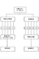
図1に示すように、適切なX線源1は、スキャニング領域を介して、X線を、3つの線形検出器3aから3cの方向に向けるように使用される。
As shown in FIG. 1, a
前述で検討したように、本発明により想定される装置は、画像を生成することによって提供される情報を用いて、相対的な比率および例えばビーム方向における奥行きを決定することができるように、本発明のエネルギーによって分解されたデータ収集と操作の態様とを組み合わせてもよい。2次元画像は、透過ビームの方向と略直交するx、y平面における情報を与え、本発明の原理は、例えば、一部の情報、例えばz方向における相対的な奥行きのレンダリングを与える。以下の例は全て、そのような2次元の放射線写真が生成されることを前提としている。 As discussed above, the apparatus envisioned by the present invention uses the information provided by generating the image so that the relative proportions and, for example, the depth in the beam direction can be determined. You may combine the data collection decomposed by the energy of the invention and the mode of operation. A two-dimensional image provides information in the x, y plane that is substantially orthogonal to the direction of the transmitted beam, and the principles of the present invention provide, for example, some information, eg, a rendering of relative depth in the z direction. The following examples all assume that such a two-dimensional radiograph is generated.
しかしながら、本発明の原理は等しく画像化のない状況にも適用可能であることは理解される。 However, it is understood that the principles of the present invention are equally applicable to situations without imaging.
この応用を考慮しつつ、図示された実施形態は、3つの線形検出器3aから3c(これらは、本実施形態において、各々検出器要素の線形配列を含む)にカーテン状の入射ビームを生成するようにコリメートされた単一のX線源を用いる。従って、複数の放射線経路5aから5cは、スキャニング領域において、そのような線形検出器の直線的または角度的に離された配列に入射する複数のカーテンビームによって生成される。入射放射線経路5aから5cは、X線源1と検出器3aから3cのそれぞれとの間のスキャニング領域を通過して示されている。
Considering this application, the illustrated embodiment produces a curtain-like incident beam on three
本実施形態において、線形配列の検出器3aから3cは、入射X線を分光学的に分解できる物質を含み、かつその特定の例として、テルル化カドミウムを含むが、当業者によれば他の物質の選択も適切であり得ると理解される。このスペクトルの分解を利用するために、X線源は広帯域エネルギースペクトルに亘ってX線を放射する。例としては、当業者によれば他の物質も適切であり得ると理解されるものの、タングステン源が用いられる。
In this embodiment, the linear array of
無端ベルトコンベヤ7は、スキャンされる物体9をスキャニング領域で放射線経路5aから5cを途中で受けるように、方向dに向けて移動させる。本発明のこの実施形態の想定される応用は、セキュリティスキャナとしてであり、物体9は様々な区別できる物体を収容すると予測される容器であると通常考えられ、それ(例えば、エアラインの預け荷物)を、物ごとに(compositionally)特徴付け、3次元で効果的に閲覧することは有益であり、かつ好適である。しかしながら、同様の原理は、例えば内部検査の目的の物体のスキャニング、医療分野のスキャニング、およびその他類似する応用に適用可能であることを当業者は容易に理解する。
The
3つの検出器3aから3cの各々からの透過情報を構築することによって、透過強度情報のデータセットが生成される。本発明の原理に基づいた数値分析と、分光学的に分解される画像化との両方の目的のために、入射エネルギー/入射波長と透過強度との間の関係を、少なくともある程度、分解することによる情報のデータセットの処理を図2から図4に示す。
By constructing transmission information from each of the three
図2に示す模式図においては、簡略化のため、単一の放射線経路のみを示す。X線源1、および水平方向に間隔を置かれた検出器装置アセンブリ21は、それらの間にスキャニング領域Zを規定する。使用中、スキャンされる物体は、例えば前述のような適切なコンベヤベルト上で、通常の方法で、スキャニング領域へ持ち込まれ、スキャニング領域を通過させられる。
In the schematic diagram shown in FIG. 2, only a single radiation path is shown for simplicity. The
図に示す例では、物体9はスキャニング領域Zに位置している。X線源からの入射ビーム11が図示されている。この簡単な模式図では、入射ビームは直線11によって示される。透過ビーム13は、検出器配列21に入射する。
In the example shown in the figure, the
検出器配列21は、プロセッサ22とデータ通信を行う。検出器配列は、既知の方法で、2次元の「薄片(スライス)」を生成するために使用される。配列の中の物質の固有のスペクトル分解によって、プロセッサ22は、データレジスタ23に蓄積されたエネルギー帯域の境界を参照することにより、本発明の原理に従って複数のプリセット周波数/エネルギー帯域に亘って差異的にこの画像を分解することが可能になる。
The
この実施形態では、タングステンのX線源が使われる。タングステンから生成された、波長に対する初期強度の典型的なスペクトルを図3に示す。 In this embodiment, a tungsten X-ray source is used. A typical spectrum of initial intensity versus wavelength generated from tungsten is shown in FIG.
図3の主な目的は、本発明の原理に従ってスペクトルが分解され得る、2つの可能な方法を示すことである。それぞれの場合において、スペクトルは5つの周波数帯域に亘って分解される。 The main purpose of FIG. 3 is to show two possible ways in which the spectrum can be resolved according to the principles of the present invention. In each case, the spectrum is resolved over five frequency bands.
模式図は、スペクトルを分解し得る、2つの方法を示している。図3(a)では、生成されたスペクトルの大部分は、5つの比較的広帯域のエネルギー帯域b1からb5に分割される。図3(b)では、個々のエネルギーに近似し得る、5つの比較的狭いエネルギー帯域がc1からc5に規定されている。どちらの選択肢も本発明の原理と矛盾せず、かつ、本発明の数値分析のため、または好ましい実施形態において、検査の対象となっている物体に関するさらなる情報を得るために分光学的に分解された画像化のため、のいずれかにつき有用な結果を得るために、いずれの組み合わせを使用してもよい。 The schematic shows two ways in which the spectrum can be resolved. In FIG. 3 (a), most of the generated spectrum is divided into five relatively wide energy bands b1 to b5. In FIG. 3 (b), five relatively narrow energy bands that can be approximated to individual energies are defined in c1 to c5. Neither option is consistent with the principles of the present invention and is resolved spectroscopically for numerical analysis of the present invention or in a preferred embodiment to obtain further information about the object being examined. Any combination may be used to obtain useful results for any of the following.
好ましい実施形態において、このデータは、画像、最も好ましくはさらなる情報を画像に与えるために、それ自体を複数の周波数帯域に亘りスペクトル分解したスペクトル分解画像を生成するのにも用いられる。このような実施形態において、図3において分解されたエネルギー帯域の幾つか、例えば、図3aに示すエネルギー帯域は、表示手段29に送信するエネルギー分化画像を形成するために使用されてよい。この点に関して、この装置は、従来のエネルギー分化画像化装置と同様の基本的原理に従う。 In a preferred embodiment, this data is also used to generate a spectrally resolved image that is itself spectrally resolved across multiple frequency bands to provide the image, most preferably further information to the image. In such an embodiment, some of the energy bands decomposed in FIG. 3, for example the energy band shown in FIG. 3a, may be used to form an energy differentiated image to be transmitted to the display means 29. In this regard, the device follows the same basic principles as a conventional energy differentiation imaging device.
この装置は、例えば図3bに示すような、一連の識別された周波数帯域と関連してさらに作動する、プロセッサ22によって提供された機能において異なるが、しかし、この機能においては、それぞれの帯域における透過強度の代表的な定量値、および例えばその平均値を生成するためにそのデータを使用し、そのデータは強度データアイテムレジスタ24へ保存のため送信される。
This device differs in the functions provided by the
計算手段25および比較器手段26は、いずれかまたは両方で、例えば特定用途向けまたは汎用のコンピュータ等のプログラミングに適したデータプロセッサを備えており、それらによって生成されたデータとデータライブラリ27とを共に作動可能なように比較する。このデータライブラリは、試験下の特定の物体のための少数の特定の標的物の物質についての質量減衰係数に関連するかまたはそれに依存する、可能性のあるまたは少なくとも数値的に比較され得る性質の事前に保存されたデータを含む。データはあらかじめロードされているかまたは参照され、あるいは、既知の物質を用いた装置の作動により、時間の経過と共に生成されるかまたは加えられてもよい。
Either or both of the calculation means 25 and the comparator means 26 include a data processor suitable for programming such as an application-specific or general-purpose computer, and the data generated by them and the
データ処理のいずれか、あるいは、例えばプロセッサ22、データレジスタ24、計算手段25、比較器手段26、およびデータライブラリ27のうちの1つ以上を含む装置の保存要素が、特定用途向けまたは汎用のコンピュータ等のプログラミングに適したデータプロセッサ手段によって提供されてもよい。
Any of the data processing or storage elements of the device, including for example one or more of
この比較によって、透過経路における、可能性が高いと見込まれる物質の内容(含有物)、および限られた数の複合物質の見込まれた比率に関する推定を行うことができる。このことは、計算手段25および比較器手段26が、各々の複合物の相対的な寄与のための重み付けと、一定の割合の内容の測定を引出すことによって、測定されたデータをライブラリに適合させるために、計算を繰り返すことを実行するように共に動作するように適合されているという点において達成される。適用される質量減衰の式は上述で説明してある。この装置が本発明の原理に従って用いられる場合、その原理の変形の全てはその源(それは固定された初期の強度および既知のスペクトルである)から既知であるか、正規化されたものであるか、または測定可能(例えば厚さなど)なものであるかのいずれかであることは理解される。透過強度全体に対して任意の実質的な寄与を生じ得るための各含有要素の質量減衰係数もまた既知である。この全体の透過された強度減衰(ここでtは既知の特定の質量減衰係数である)は、特定の周波数において、強度データセットから、計算手段25および比較器手段26によって容易にかつ数値的に決定可能である。任意の単一の特定の周波数において既知でない質量減衰係数については、各々個々の含有要素がその減衰全体に対して寄与している。しかしながら、各含有要素の質量減衰係数はエネルギーの変化に伴い特徴的かつ相違して様々である。従って、全ての構成要素についての既知の質量減衰係数の全てのデータを、各エネルギーでの計算された値に適合させることによって、各構成要素の相対的な比率について一意の解答を導き出すことは、原則として本発明に従えば少なくとも可能である。この一意の解答は、例えば、画像表示29に関連して、表示手段30に送られることができる。分離したその値に加えて、これは、表示手段29上に表示された画像と連動して用いられてもよく、それによってより良く検査下の物体の内容または合成物を特徴付けることができる。
By this comparison, an estimate can be made regarding the content (inclusions) of likely substances in the permeation path and the expected ratio of a limited number of complex substances. This means that the calculation means 25 and the comparator means 26 fit the measured data into the library by drawing weights for the relative contribution of each compound and a certain percentage of the content. This is achieved in that they are adapted to work together to perform repeating calculations. The applied mass attenuation equation is described above. If this device is used in accordance with the principles of the present invention, are all variations of that principle known or normalized from its source (which is a fixed initial intensity and known spectrum)? Or is measurable (eg, thickness, etc.). The mass attenuation coefficient of each containing element is also known to be able to make any substantial contribution to the overall transmission intensity. This total transmitted intensity attenuation (where t is a known specific mass attenuation coefficient) is easily and numerically calculated from the intensity data set by the calculating means 25 and the comparator means 26 at a specific frequency. Can be determined. For unknown mass attenuation factors at any single particular frequency, each individual containing element contributes to the overall attenuation. However, the mass attenuation coefficient of each containing element varies characteristically and differently with changes in energy. Therefore, deriving a unique solution for the relative proportions of each component by fitting all the data for the known mass attenuation coefficients for all components to the calculated values at each energy is In principle, it is at least possible according to the invention. This unique answer can be sent to the display means 30 in connection with the
このように、本発明に従い、試験下の物体の可能性が高いと見込まれた構成要素の提供された概略的な知識が利用可能であり、これらの可能性のある構成要素に懸かるデータは保存可能であり、相対的な合成物の情報が取得可能である。これは、2次元のX線画像を3方向における構造の描写で補うために用いられてよい。 Thus, in accordance with the present invention, the provided general knowledge of the components that are likely to be the object under test is available and the data on these potential components is stored. It is possible to obtain information on relative composites. This may be used to supplement a two-dimensional X-ray image with a description of the structure in three directions.
例えば、データライブラリ27はまた、物体のおよそのモデル構造を保存してもよい。上述の繰返しの計算処理がいったん行われて、透過経路における各々の構成要素の相対的な比率についての、および全体に対するそれらの相対的な奥行きの寄与についての特定のデータを導き出し、各々の構成要素に対する相対的な奥行き値が生成でき、かつそれらの値が、透過方向におけるモデル画像を生成するためにそのモデルに適合させることができる。これは、そのデータのある程度の体積レンダリングを与えるために、従来の方法において、上述のように生成された透過方向に直交する平面において、特定の透過放射線撮影に連動して用いられることができる。基本的には、データは、2次元においてのみ特定の透過情報を有しているが、一部の3次元でのモデリングは、この装置のスペクトル分解を利用して相対的に少数の予期された、または可能性のある構成要素の相対的な比率を導き出すことによって、本発明に従い可能となる。
For example, the
データ収集及び操作のプロセスは、図4のフローチャートによって示され、透過強度のスペクトル分解が本発明の数値識別プロセス、および追加的な画像化目的の両方のために使用される好ましい実施形態を示す。初めから終りまで読み進むに従って、収集されたデータセットは、一連の画像帯域、および図3で示される方法による数値分析のための一連の帯域の両方に分解される。 The data collection and manipulation process is illustrated by the flowchart of FIG. 4, which illustrates a preferred embodiment in which the spectral decomposition of transmission intensity is used for both the numerical identification process of the present invention and for additional imaging purposes. As we read from beginning to end, the collected data set is broken down into both a series of image bands and a series of bands for numerical analysis by the method shown in FIG.
透過強度データセットの画像帯域への分解は、相対的に広い帯域ではあるがスペクトル全体に亘ってエネルギーによって分化された帯域に亘って透過X線の強度を共に示す一連の画像b1、b2、b3、b4、及びb5を生成する。このように、異なる合成物の物体の間におけるある程度の識別が可能である。異なる合成物の、特に異なる原子数の物質は、異なる反応を示す傾向がある。異なる画像b1からb5が、例えば連続して表示され、またはより好ましくは区別するために着色され、単一の合成物の画像に同時に表示される場合、スキャンからさらなる物体の分解が可能である。このプロセスは、合理的に従来から行われている。 The decomposition of the transmitted intensity data set into image bands is a series of images b1, b2, b3 that together show the intensity of transmitted X-rays over a relatively wide band but over a band differentiated by energy over the entire spectrum. , B4, and b5 are generated. In this way, a certain degree of discrimination between different composite objects is possible. Different compounds, especially those with different numbers of atoms, tend to show different reactions. If different images b1 to b5 are displayed successively, for example, or more preferably colored for distinction and displayed simultaneously on a single composite image, further object decomposition from the scan is possible. This process is reasonably conventional.
本発明が特に異なる点は、透過強度データセットの帯域c1からc5への追加的な分解にある。実施形態において、これらの帯域は比較的狭いが、これは一例に過ぎない。原理上は、同じ帯域を両方の目的に使用できない理由はない。これらの帯域に関して分解されたレジスタ25の透過データは強度データを生成するために前述のように処理され、次いで比較器は、物質の比率的内容に関する推定を可能にするために、同等の保存されたデータを参照する。これは、例えば、画像化帯域の分解から生成された複雑な画像との組み合わせによって、または追加情報の表示として画像と共に、または特注ディスプレイに表示され得る。
The particular difference of the present invention is the additional decomposition of the transmission intensity data set into bands c1 to c5. In an embodiment, these bands are relatively narrow, but this is only an example. In principle, there is no reason why the same band cannot be used for both purposes. The transmission data of
本発明は、特に画像を表示しないモードで作動する場合、単一の放射線経路のみを必要とするが、図1の実施形態は、物体を通過する複数の放射線経路を示す。図5は、図1の実施形態によって設けられた複数の放射線経路を用いて生成された画像によって形成され得る追加の効果を示し、これは、提供された情報を更に強化することができる。物体9が入射放射線経路5aから5c(図5(a)を参照)を通過すると、物体がX線源1に対して異なる方向を向いた3つの画像が生成される。これらの画像の連続する表示によって、物体は図5(b)に示すように、回転するように見える。3次元内で実質的に回転可能な物体の表示を得る能力は、画像表示をさらに向上させることができる。
While the present invention requires only a single radiation path, especially when operating in a non-image display mode, the embodiment of FIG. 1 shows multiple radiation paths through the object. FIG. 5 illustrates an additional effect that can be formed by an image generated using multiple radiation paths provided by the embodiment of FIG. 1, which can further enhance the information provided. When the
Claims (22)
放射線源および放射線検出器システムを提供する工程であって、前記放射線検出器システムは前記放射線源から間隔を置いて配置され、それらの間にあるスキャニング領域を規定し、前記検出器システムは、入射放射線についての分光学的に分解可能な情報を検出および収集することができる、工程と、
前記検出器システムに入射する放射線についての強度情報の1つ以上のデータセット、および前記スキャニング領域における物体の少なくとも1つのスキャニング位置における透過率を、前記物体から透過され前記検出器システムにおいて受信される放射線から、収集する工程と、
各々の前記強度データセットを、前記放射線源のスペクトル内の複数の周波数または周波数帯域に亘って、各々の周波数/周波数帯域に対する強度データアイテムを生成するために、分解する工程と、
前記スキャニング領域における前記物体の複数の予期される構成要素の物質のために、各々の強度データアイテムを、前記構成要素の物質に関して、指数関数的な減衰則、すなわち
l/l0=exp[−(μ/ρ)ρt]
によって与えられる関係に適合させ、かつ、前記構成要素の物質から、前記強度データアイテムを生成する透過経路内の各々の要素の物質の相対的な比率の指標を導き出すために、前記強度データアイテムを数値的に、質量減衰データを保存する質量減衰データライブラリと比較する工程と、
を含む方法。 A method for acquiring radiation transmission data from an object,
Providing a radiation source and a radiation detector system, wherein the radiation detector system is spaced from the radiation source and defines a scanning region therebetween, the detector system comprising an incident A process capable of detecting and collecting spectroscopically resolvable information about radiation; and
One or more data sets of intensity information about radiation incident on the detector system and the transmittance at at least one scanning position of the object in the scanning region are transmitted from the object and received at the detector system. Collecting from radiation, and
Decomposing each said intensity data set to generate intensity data items for each frequency / frequency band across multiple frequencies or frequency bands in the spectrum of said radiation source;
For a plurality of expected component materials of the object in the scanning region, each intensity data item is exponentially reduced with respect to the component material, ie, l / l 0 = exp [− (Μ / ρ) ρt]
To derive an indication of the relative proportion of each elemental substance in the permeation path that produces the intensity data item from the constituent substance and to match the relationship given by Numerically comparing to a mass attenuation data library storing mass attenuation data;
Including methods.
強度データアイテムについて、その周波数にて、質量減衰係数全体を導き出す工程と、
前記周波数において、前記各々の要素の物質についての質量減衰係数を読み出す工程と、
前記強度データアイテムを生成するために必要な各々の要素の相対的な比率に対して、単一の一意の解答が導き出され得ることを、十分な周波数にて繰り返す工程と、
を含む、請求項1に記載の方法。 The step of comparing the intensity data items comprises:
Deriving the entire mass attenuation coefficient at the frequency for the intensity data item;
Reading the mass attenuation coefficient for the material of each of the elements at the frequency;
Repeating at a sufficient frequency that a single unique answer can be derived for the relative proportions of each element required to generate the intensity data item;
The method of claim 1 comprising:
放射線源および放射線検出器システムであって、前記放射線検出器システムは前記放射線源から間隔を置いて配置され、それらの間にあるスキャニング領域を規定し、使用の際、前記検出器システムに入射する放射線についての情報のデータセット、および前記スキャニング領域における物体の少なくとも1つのスキャニング位置における透過率を収集する、放射線源および放射線検出器システムと、
各々のそのようなデータセットまたは画像を、前記放射線源のスペクトル内の複数の周波数に亘って、各々の周波数に対する強度データアイテムを生成するために、分光学的に処理および分解するデータ処理装置と、
試験下の物体の複数の予期される構成要素の物質のために、質量減衰データを保存する質量減衰データライブラリと、
各々の強度データアイテムを、前記構成要素の物質に関して、指数関数的な減衰則、すなわち
l/l0=exp[−(μ/ρ)ρt]
によって与えられる関係に適合させ、かつ前記構成要素の物質から、前記強度データアイテムを生成する透過経路内の各々の構成要素の物質の相対的な比率の指標を導き出す比較器と、
を備える、装置。 An apparatus for scanning and acquiring radiation transmission data from an object,
A radiation source and a radiation detector system, wherein the radiation detector system is spaced from the radiation source, defines a scanning region therebetween, and enters the detector system in use A radiation source and radiation detector system for collecting a data set of information about radiation and transmission at at least one scanning position of an object in said scanning region;
A data processing device for spectroscopically processing and decomposing each such data set or image to generate intensity data items for each frequency over a plurality of frequencies in the spectrum of the radiation source; ,
A mass attenuation data library that stores mass attenuation data for substances of multiple expected components of the object under test;
Each intensity data item is an exponential decay law with respect to the constituent materials, i.e. l / l 0 = exp [− (μ / ρ) ρt].
A comparator adapted to the relationship given by and deriving from the component material an indicator of the relative proportion of each component material in the permeation path that produces the intensity data item;
An apparatus comprising:
強度データアイテムについて、その周波数にて、質量減衰係数全体を導き出し、
前記周波数において、前記各々の構成要素の物質についての質量減衰係数を読み出し、
各々の構成要素の物質の前記相対的な比率を、前記強度データアイテムに適合するように、単一の一意の解答が導き出され得ることを、十分な周波数にて繰り返すように適合された計算手段を備える、請求項12に記載の装置。 The comparator is
For an intensity data item, derive the overall mass attenuation coefficient at that frequency,
Read the mass attenuation coefficient for each constituent material at the frequency,
Computation means adapted to repeat at a sufficient frequency that a single unique answer can be derived so that the relative proportions of each constituent substance fit the intensity data item. The apparatus of claim 12, comprising:
Applications Claiming Priority (3)
| Application Number | Priority Date | Filing Date | Title |
|---|---|---|---|
| GB0807473.4 | 2008-04-24 | ||
| GBGB0807473.4A GB0807473D0 (en) | 2008-04-24 | 2008-04-24 | Method and Apparatus for Inspection of Materials |
| PCT/GB2009/050270 WO2009130491A1 (en) | 2008-04-24 | 2009-03-24 | Method and apparatus for inspection of materials |
Related Child Applications (1)
| Application Number | Title | Priority Date | Filing Date |
|---|---|---|---|
| JP2014169657A Division JP2014238422A (en) | 2008-04-24 | 2014-08-22 | Method and apparatus for inspection of material |
Publications (1)
| Publication Number | Publication Date |
|---|---|
| JP2011519031A true JP2011519031A (en) | 2011-06-30 |
Family
ID=40133679
Family Applications (2)
| Application Number | Title | Priority Date | Filing Date |
|---|---|---|---|
| JP2011505594A Pending JP2011519031A (en) | 2008-04-24 | 2009-03-24 | Method and apparatus for inspecting substances |
| JP2014169657A Pending JP2014238422A (en) | 2008-04-24 | 2014-08-22 | Method and apparatus for inspection of material |
Family Applications After (1)
| Application Number | Title | Priority Date | Filing Date |
|---|---|---|---|
| JP2014169657A Pending JP2014238422A (en) | 2008-04-24 | 2014-08-22 | Method and apparatus for inspection of material |
Country Status (5)
| Country | Link |
|---|---|
| US (1) | US8537968B2 (en) |
| EP (1) | EP2269043B1 (en) |
| JP (2) | JP2011519031A (en) |
| GB (1) | GB0807473D0 (en) |
| WO (1) | WO2009130491A1 (en) |
Cited By (2)
| Publication number | Priority date | Publication date | Assignee | Title |
|---|---|---|---|---|
| JP2017528735A (en) * | 2014-08-16 | 2017-09-28 | エフ・イ−・アイ・カンパニー | Tomographic reconstruction for material characterization |
| WO2020250704A1 (en) * | 2019-06-11 | 2020-12-17 | キヤノン株式会社 | Radiographic imaging device and radiographic imaging method |
Families Citing this family (15)
| Publication number | Priority date | Publication date | Assignee | Title |
|---|---|---|---|---|
| US8243876B2 (en) | 2003-04-25 | 2012-08-14 | Rapiscan Systems, Inc. | X-ray scanners |
| GB0525593D0 (en) | 2005-12-16 | 2006-01-25 | Cxr Ltd | X-ray tomography inspection systems |
| JP5559471B2 (en) * | 2008-11-11 | 2014-07-23 | 浜松ホトニクス株式会社 | Radiation detection apparatus, radiation image acquisition system, radiation inspection system, and radiation detection method |
| GB2501661B (en) | 2011-02-22 | 2017-04-12 | Rapiscan Systems Inc | X-ray inspection system and method |
| BG66598B1 (en) * | 2011-02-25 | 2017-08-31 | Габрово, Технически Университет | A method for finding and determination of substances or mixtures and/or determination of their characteristics |
| EP2806264B1 (en) * | 2012-01-20 | 2018-10-31 | Nikon Corporation | X-ray device, method, manufacturing method for structure, program, and recording medium on which program is recorded |
| CN102749342B (en) * | 2012-07-20 | 2014-12-10 | 贵州电力试验研究院 | Non-destructive identification method for material of integral coil of distribution transformer |
| CA2925947C (en) | 2013-10-01 | 2020-12-22 | Voti Inc. | Scanning system, method, and corresponding bracket |
| GB201318998D0 (en) | 2013-10-28 | 2013-12-11 | Kromek Ltd | Method and apparatus for the scanning of contained materials |
| JP6397690B2 (en) * | 2014-08-11 | 2018-09-26 | 株式会社日立ハイテクノロジーズ | X-ray transmission inspection apparatus and foreign object detection method |
| FR3073044B1 (en) * | 2017-10-27 | 2020-10-02 | Tiama | METHOD AND DEVICE FOR MEASURING DIMENSIONS BY X-RAYS, ON EMPTY GLASS CONTAINERS RUNNING IN LINE |
| WO2020082171A1 (en) | 2018-10-22 | 2020-04-30 | Voti Inc. | Tray insert for screening tray |
| CN112666194B (en) * | 2020-12-22 | 2022-12-20 | 上海培云教育科技有限公司 | Virtual digital DR image generation method and DR virtual simulation instrument |
| US11885752B2 (en) | 2021-06-30 | 2024-01-30 | Rapiscan Holdings, Inc. | Calibration method and device therefor |
| CN117109494B (en) * | 2023-10-23 | 2024-01-23 | 北京华力兴科技发展有限责任公司 | Intelligent calibration method for X-ray thickness gauge |
Citations (8)
| Publication number | Priority date | Publication date | Assignee | Title |
|---|---|---|---|---|
| JPS62113007A (en) * | 1985-11-12 | 1987-05-23 | Sumitomo Metal Ind Ltd | Absorption x-ray analyzer |
| JPH01172739A (en) * | 1987-12-28 | 1989-07-07 | Matsushita Electric Ind Co Ltd | Radiation measuring instrument |
| JPH04369460A (en) * | 1991-06-17 | 1992-12-22 | Nippon Steel Corp | Density measuring apparatus |
| JPH06121791A (en) * | 1992-10-13 | 1994-05-06 | Matsushita Electric Ind Co Ltd | X-ray determination device and x-ray determination method |
| JP2005192657A (en) * | 2003-12-26 | 2005-07-21 | Aloka System Engineering Co Ltd | X-ray ct equipment |
| JP2007218845A (en) * | 2006-02-20 | 2007-08-30 | Shimadzu Corp | Transmission x-ray measuring method |
| JPWO2007122770A1 (en) * | 2006-04-13 | 2009-08-27 | 株式会社島津製作所 | Three-dimensional quantitative method using transmitted X-ray |
| JP2010537163A (en) * | 2007-08-17 | 2010-12-02 | ダーハム サイエンティフィック クリスタルズ リミテッド | Method and apparatus for inspection of substances |
Family Cites Families (13)
| Publication number | Priority date | Publication date | Assignee | Title |
|---|---|---|---|---|
| US3845963A (en) | 1971-12-08 | 1974-11-05 | Emhart Corp | Adjustable chuck for containers or vials |
| US3818232A (en) | 1972-12-13 | 1974-06-18 | Nuclearay Inc | Container fill level inspector with product averaging system |
| US5493596A (en) | 1993-11-03 | 1996-02-20 | Annis; Martin | High-energy X-ray inspection system |
| US6018562A (en) * | 1995-11-13 | 2000-01-25 | The United States Of America As Represented By The Secretary Of The Army | Apparatus and method for automatic recognition of concealed objects using multiple energy computed tomography |
| US6540367B1 (en) * | 1999-04-07 | 2003-04-01 | 3M Innovative Properties Company | Structured surface articles containing geometric structures with compound faces and methods for making same |
| US6246747B1 (en) | 1999-11-01 | 2001-06-12 | Ge Lunar Corporation | Multi-energy x-ray machine with reduced tube loading |
| WO2004095060A2 (en) * | 2003-04-23 | 2004-11-04 | L-3 Communications Security and Detection Systems Corporation | X-ray imaging technique |
| DE102005008767A1 (en) * | 2005-02-25 | 2006-09-07 | Siemens Ag | Method for an X-ray device and computer tomograph for reducing beam hardening artifacts from a generated image of an object |
| DE102005049586A1 (en) | 2005-10-17 | 2007-04-26 | Siemens Ag | Method for generating computerized tomography displays in x-ray computed tomography, comprises scanning an object and reconstructing a first computerized tomography display from an absorption data of an energy spectrum |
| GB2433315B (en) | 2005-12-17 | 2008-07-09 | Schlumberger Holdings | Method and system for analyzing multi-phase mixtures |
| US7376215B2 (en) * | 2005-12-27 | 2008-05-20 | Honeywell International Inc. | Measurement of ash composition using scanning high voltage X-ray sensor |
| US8000440B2 (en) | 2006-07-10 | 2011-08-16 | Agresearch Limited | Target composition determination method and apparatus |
| GB0807474D0 (en) * | 2008-04-24 | 2008-12-03 | Durham Scient Crystals Ltd | Determination of Composition of Liquids |
-
2008
- 2008-04-24 GB GBGB0807473.4A patent/GB0807473D0/en not_active Ceased
-
2009
- 2009-03-24 US US12/989,035 patent/US8537968B2/en active Active
- 2009-03-24 JP JP2011505594A patent/JP2011519031A/en active Pending
- 2009-03-24 WO PCT/GB2009/050270 patent/WO2009130491A1/en active Application Filing
- 2009-03-24 EP EP09735300.7A patent/EP2269043B1/en active Active
-
2014
- 2014-08-22 JP JP2014169657A patent/JP2014238422A/en active Pending
Patent Citations (8)
| Publication number | Priority date | Publication date | Assignee | Title |
|---|---|---|---|---|
| JPS62113007A (en) * | 1985-11-12 | 1987-05-23 | Sumitomo Metal Ind Ltd | Absorption x-ray analyzer |
| JPH01172739A (en) * | 1987-12-28 | 1989-07-07 | Matsushita Electric Ind Co Ltd | Radiation measuring instrument |
| JPH04369460A (en) * | 1991-06-17 | 1992-12-22 | Nippon Steel Corp | Density measuring apparatus |
| JPH06121791A (en) * | 1992-10-13 | 1994-05-06 | Matsushita Electric Ind Co Ltd | X-ray determination device and x-ray determination method |
| JP2005192657A (en) * | 2003-12-26 | 2005-07-21 | Aloka System Engineering Co Ltd | X-ray ct equipment |
| JP2007218845A (en) * | 2006-02-20 | 2007-08-30 | Shimadzu Corp | Transmission x-ray measuring method |
| JPWO2007122770A1 (en) * | 2006-04-13 | 2009-08-27 | 株式会社島津製作所 | Three-dimensional quantitative method using transmitted X-ray |
| JP2010537163A (en) * | 2007-08-17 | 2010-12-02 | ダーハム サイエンティフィック クリスタルズ リミテッド | Method and apparatus for inspection of substances |
Cited By (4)
| Publication number | Priority date | Publication date | Assignee | Title |
|---|---|---|---|---|
| JP2017528735A (en) * | 2014-08-16 | 2017-09-28 | エフ・イ−・アイ・カンパニー | Tomographic reconstruction for material characterization |
| US10311606B2 (en) | 2014-08-16 | 2019-06-04 | Fei Company | Correction of beam hardening artifacts in microtomography for samples imaged in containers |
| US10354418B2 (en) | 2014-08-16 | 2019-07-16 | Fei Company | Tomographic reconstruction for material characterization |
| WO2020250704A1 (en) * | 2019-06-11 | 2020-12-17 | キヤノン株式会社 | Radiographic imaging device and radiographic imaging method |
Also Published As
| Publication number | Publication date |
|---|---|
| US8537968B2 (en) | 2013-09-17 |
| JP2014238422A (en) | 2014-12-18 |
| GB0807473D0 (en) | 2008-12-03 |
| WO2009130491A1 (en) | 2009-10-29 |
| EP2269043B1 (en) | 2019-07-03 |
| US20110116605A1 (en) | 2011-05-19 |
| EP2269043A1 (en) | 2011-01-05 |
Similar Documents
| Publication | Publication Date | Title |
|---|---|---|
| JP2014238422A (en) | Method and apparatus for inspection of material | |
| JP5670730B2 (en) | Method and apparatus for inspection of substances | |
| EP2147297B1 (en) | Inspection of materials by evaluating the contribution of bragg scattering to energy dispersive x-ray attenuation | |
| JP5580291B2 (en) | Determination of liquid composition | |
| US20100223016A1 (en) | Method and apparatus for identification and detection of liquids | |
| US8781072B2 (en) | Apparatus and method for characterisation of materials | |
| WO2008142446A2 (en) | Energy dispersive x-ray absorption spectroscopy in scanning transmission mode involving the calculation of the intensity ratios between successive frequency bands | |
| JP5981543B2 (en) | Substance detection and / or classification | |
| US8478016B2 (en) | Radiographic data interpretation | |
| JP5981545B2 (en) | Radiation inspection method for objects | |
| EP3063533B1 (en) | Method and apparatus for the inspection of contained materials |
Legal Events
| Date | Code | Title | Description |
|---|---|---|---|
| A621 | Written request for application examination |
Free format text: JAPANESE INTERMEDIATE CODE: A621 Effective date: 20120305 |
|
| A977 | Report on retrieval |
Free format text: JAPANESE INTERMEDIATE CODE: A971007 Effective date: 20130619 |
|
| A131 | Notification of reasons for refusal |
Free format text: JAPANESE INTERMEDIATE CODE: A131 Effective date: 20130625 |
|
| A601 | Written request for extension of time |
Free format text: JAPANESE INTERMEDIATE CODE: A601 Effective date: 20130925 |
|
| A602 | Written permission of extension of time |
Free format text: JAPANESE INTERMEDIATE CODE: A602 Effective date: 20131002 |
|
| A02 | Decision of refusal |
Free format text: JAPANESE INTERMEDIATE CODE: A02 Effective date: 20140422 |
|
| A521 | Written amendment |
Free format text: JAPANESE INTERMEDIATE CODE: A523 Effective date: 20140822 |
|
| A911 | Transfer to examiner for re-examination before appeal (zenchi) |
Free format text: JAPANESE INTERMEDIATE CODE: A911 Effective date: 20140901 |
|
| A912 | Re-examination (zenchi) completed and case transferred to appeal board |
Free format text: JAPANESE INTERMEDIATE CODE: A912 Effective date: 20141010 |