JP2011508427A - Laser diode compensation method and apparatus - Google Patents
Laser diode compensation method and apparatus Download PDFInfo
- Publication number
- JP2011508427A JP2011508427A JP2010539552A JP2010539552A JP2011508427A JP 2011508427 A JP2011508427 A JP 2011508427A JP 2010539552 A JP2010539552 A JP 2010539552A JP 2010539552 A JP2010539552 A JP 2010539552A JP 2011508427 A JP2011508427 A JP 2011508427A
- Authority
- JP
- Japan
- Prior art keywords
- laser diode
- value
- laser
- brightness
- luminance
- Prior art date
- Legal status (The legal status is an assumption and is not a legal conclusion. Google has not performed a legal analysis and makes no representation as to the accuracy of the status listed.)
- Pending
Links
Images


Classifications
-
- H—ELECTRICITY
- H01—ELECTRIC ELEMENTS
- H01S—DEVICES USING THE PROCESS OF LIGHT AMPLIFICATION BY STIMULATED EMISSION OF RADIATION [LASER] TO AMPLIFY OR GENERATE LIGHT; DEVICES USING STIMULATED EMISSION OF ELECTROMAGNETIC RADIATION IN WAVE RANGES OTHER THAN OPTICAL
- H01S5/00—Semiconductor lasers
- H01S5/06—Arrangements for controlling the laser output parameters, e.g. by operating on the active medium
- H01S5/068—Stabilisation of laser output parameters
- H01S5/0683—Stabilisation of laser output parameters by monitoring the optical output parameters
-
- H—ELECTRICITY
- H04—ELECTRIC COMMUNICATION TECHNIQUE
- H04N—PICTORIAL COMMUNICATION, e.g. TELEVISION
- H04N9/00—Details of colour television systems
- H04N9/12—Picture reproducers
- H04N9/31—Projection devices for colour picture display, e.g. using electronic spatial light modulators [ESLM]
- H04N9/3129—Projection devices for colour picture display, e.g. using electronic spatial light modulators [ESLM] scanning a light beam on the display screen
-
- H—ELECTRICITY
- H04—ELECTRIC COMMUNICATION TECHNIQUE
- H04N—PICTORIAL COMMUNICATION, e.g. TELEVISION
- H04N9/00—Details of colour television systems
- H04N9/12—Picture reproducers
- H04N9/31—Projection devices for colour picture display, e.g. using electronic spatial light modulators [ESLM]
- H04N9/3141—Constructional details thereof
- H04N9/315—Modulator illumination systems
- H04N9/3155—Modulator illumination systems for controlling the light source
-
- H—ELECTRICITY
- H01—ELECTRIC ELEMENTS
- H01S—DEVICES USING THE PROCESS OF LIGHT AMPLIFICATION BY STIMULATED EMISSION OF RADIATION [LASER] TO AMPLIFY OR GENERATE LIGHT; DEVICES USING STIMULATED EMISSION OF ELECTROMAGNETIC RADIATION IN WAVE RANGES OTHER THAN OPTICAL
- H01S5/00—Semiconductor lasers
- H01S5/06—Arrangements for controlling the laser output parameters, e.g. by operating on the active medium
- H01S5/0617—Arrangements for controlling the laser output parameters, e.g. by operating on the active medium using memorised or pre-programmed laser characteristics
-
- H—ELECTRICITY
- H01—ELECTRIC ELEMENTS
- H01S—DEVICES USING THE PROCESS OF LIGHT AMPLIFICATION BY STIMULATED EMISSION OF RADIATION [LASER] TO AMPLIFY OR GENERATE LIGHT; DEVICES USING STIMULATED EMISSION OF ELECTROMAGNETIC RADIATION IN WAVE RANGES OTHER THAN OPTICAL
- H01S5/00—Semiconductor lasers
- H01S5/06—Arrangements for controlling the laser output parameters, e.g. by operating on the active medium
- H01S5/068—Stabilisation of laser output parameters
- H01S5/06812—Stabilisation of laser output parameters by monitoring or fixing the threshold current or other specific points of the L-I or V-I characteristics
Abstract
【課題】
レーザ投影システムにおける非線形性を補整するレーザダイオード補整方法及び装置を提供する。
【解決手段】
レーザダイオード(110)の輝度はレーザダイオード駆動電流の関数である。輝度はまたエージングや温度等の他要因の関数でもある。レーザ投影装置(100)はレーザダイオードを含んでおり、コマンドされた輝度に応じて発光する。また、フォトダイオード(120)を含んでおり、測定輝度を提供する。コマンドされた輝度と測定された輝度は比較され、レーザダイオード駆動電流はレーザダイオード特性の変動を補整するように調整される。
【選択図】 図1【Task】
A laser diode correction method and apparatus for correcting non-linearities in a laser projection system is provided.
[Solution]
The brightness of the laser diode (110) is a function of the laser diode drive current. Luminance is also a function of other factors such as aging and temperature. The laser projector (100) includes a laser diode, and emits light according to the commanded luminance. A photodiode (120) is also included to provide measured brightness. The commanded brightness and the measured brightness are compared and the laser diode drive current is adjusted to compensate for variations in laser diode characteristics.
[Selection] Figure 1
Description
一般的に本発明はレーザ投影システムに関する。特には、レーザ投影システムにおける非線形性の補整に関する。 The present invention generally relates to laser projection systems. In particular, it relates to non-linearity compensation in laser projection systems.
レーザダイオードは電流がダイオードに通電すると発光する。レーザダイオードの出力輝度はダイオードに通電される駆動電流の変化に伴い変動する。レーザダイオードの出力輝度は他の要因でも変動する。例えば、レーザダイオードの出力輝度は時間の経過(使用による劣化;以降“エージング”)によって変動する。また、例えばレーザダイオードの出力輝度はダイオードの温度の変化に連れて変動する。この変動は問題である。なぜならレーザダイオードの温度は、周囲の温度の変化、およびダイオードの“自己発熱”を招く履歴駆動電流(historical drive current)によって影響を受けるからである。 The laser diode emits light when current is passed through the diode. The output luminance of the laser diode fluctuates with a change in drive current that is passed through the diode. The output brightness of the laser diode varies depending on other factors. For example, the output brightness of a laser diode varies over time (deterioration due to use; hereinafter “aging”). Further, for example, the output luminance of the laser diode varies with changes in the temperature of the diode. This variation is a problem. This is because the temperature of the laser diode is affected by changes in ambient temperature and the historical drive current that causes “self-heating” of the diode.
発光のためにレーザダイオードを利用するレーザ投影器は、エージング、温度変化およびその他の要因による輝度の変動による影響を受ける。これらの問題はモノクロ投影器であってもカラー投影器であっても発生する。例えば、モノクロレーザ投影器は徐々に非均質なグレースケールの表示となる。同様に、カラー投影器の各カラーレーザダイオードの輝度が変動すると、表示画像の様々なカラーの輝度が変動する。異なるカラーレーザダイオードが輝度に影響を及ぼす要因(例:エージング、温度、等々)に対してそれぞれ異なる反応を示すならカラーバランスも影響を受ける。 Laser projectors that utilize laser diodes for light emission are subject to brightness variations due to aging, temperature changes, and other factors. These problems occur in both monochrome projectors and color projectors. For example, a monochrome laser projector gradually displays a non-homogeneous gray scale. Similarly, when the luminance of each color laser diode of the color projector varies, the luminance of various colors of the display image varies. If different color laser diodes react differently to factors that affect luminance (eg aging, temperature, etc.), the color balance is also affected.
本発明は、レーザ投影システムにおける非線形性を補整するレーザダイオード補整方法及び装置を提供する。 The present invention provides a laser diode compensation method and apparatus that compensates for non-linearities in a laser projection system.
本願発明の装置は、輝度特性を出力する非線形電流を有したレーザダイオードと、所望輝度値を公称レーザダイオード電流値にマッピングさせるルックアップテーブルと、前記公称レーザダイオード電流値と利得値とを乗算させるようにカップリングされたマルチプライヤと、実際の出力輝度を測定し、前記利得値を調整するフィードバックループと、を含んでいることを特徴としている。 The apparatus of the present invention multiplies a laser diode having a nonlinear current that outputs luminance characteristics, a lookup table that maps a desired luminance value to a nominal laser diode current value, and the nominal laser diode current value and a gain value. And a feedback loop that measures the actual output luminance and adjusts the gain value.
以下の詳細な説明中にて、本発明を実施する実施態様、あるいは特定の実施例を図示する添付図面に関連させて本発明が説明されている。これら実施態様または実施例は、本技術分野の専門家が本発明を実施するのに十分な程度に解説されている。本発明の様々な実施態様は、それぞれ異なってはいるものの相互排他的ではない。例えば、1実施態様に関して説明されている特定の様式、構造または特徴は、本発明の思想及び範囲から逸脱せずに他の実施態様においても利用できる。さらに、それぞれ開示された実施態様の個別要素の位置または配置は本発明の思想及び範囲から逸脱せずに修正が可能である。従って、以下の詳細な説明は本発明の限定要因として理解されるべきではなく、本発明の真の範囲は「請求の範囲」に定義されたものであり、その文言から解釈されるべきであり、請求の範囲がカバーする全均等物が含まれる。図面を通して同一物または類似物には同一番号が付されている。 In the following detailed description, the present invention is described with reference to the embodiments embodying the invention or the accompanying drawings illustrating specific embodiments. These embodiments or examples have been described to the extent sufficient to enable those skilled in the art to practice the invention. Various embodiments of the present invention are different but not mutually exclusive. For example, a particular style, structure or feature described with respect to one embodiment may be utilized in other embodiments without departing from the spirit and scope of the present invention. Further, the position or arrangement of individual elements in each disclosed embodiment can be modified without departing from the spirit and scope of the invention. The following detailed description is, therefore, not to be construed as a limiting factor of the invention, and the true scope of the invention is defined by the appended claims and should be construed from the language. All equivalents covered by the claims are included. Throughout the drawings, the same or similar items are given the same numbers.
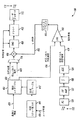
図1はレーザダイオード駆動電流補整機能を備えたレーザ投影装置を図示する。このレーザ投影装置100はノード101の所望輝度値に応じてレーザ光112を発生させる。この輝度値はどのような適したデータ源によっても発生させることができ、得られたレーザ光は任意の目的で投影できる。実施態様によっては、例えば画像処理装置は所望の輝度値を提供し、レーザ投影装置100が画像を表示する。
FIG. 1 illustrates a laser projection apparatus having a laser diode drive current compensation function. The
レーザ投影装置100は、輝度-駆動電流(L-I)マッピング102、マルチプレクサ104、マルチプライヤ106、デジタル-アナログ変換器(DAC)とドライバ108、およびレーザダイオード110を含む。レーザ投影装置100は、フォトダイオード120、トランスインピーダンスアンプリファイヤ(I-V AMP)122、アナログ-デジタル変換器(ADC)124、およびフィードバック処理コンポーネント130を含むフィードバックループも備えている。
レーザダイオード110は輝度特性を出力するために非線形の駆動電流を有している。典型的なレーザダイオード特性は図2の曲線220で示されている。マッピングコンポーネント102は実質的にレーザダイオード特性の逆特性を履行する。典型的なマッピングコンポーネント特性は図2の曲線210で示される。マッピングコンポーネント特性がレーザダイオード特性と組み合わされると、実質的に線形特性となる結果が得られる(図2の直線230)。
The
温度およびエージングを含む様々な要因によりレーザダイオード特性は時間と共に変化する。例えば図3はレーザダイオード曲線の一群を図示する。図3で示すように、レーザダイオード出力輝度は、どの曲線がレーザダイオードの作動を正確に反映するかによって、同一駆動電流に対して異なる値をとる。 Laser diode characteristics change over time due to various factors including temperature and aging. For example, FIG. 3 illustrates a group of laser diode curves. As shown in FIG. 3, the laser diode output brightness takes different values for the same drive current depending on which curve accurately reflects the operation of the laser diode.
曲線320はレーザダイオードの公称動作条件を説明する。例えば25℃で動作する新ダイオードは曲線320に従う。温度の上昇に連れて、及び/又はダイオードが古くなるに従い、ダイオードの動作は右側の曲線(例:曲線330)によって一層正確に説明される。温度が下降すると、ダイオードの動作は左側の曲線(例:曲線310)によって一層正確に説明される。レーザ投影装置の動作中に、レーザダイオードの動作特性は図3に示す一群の曲線間で連続的に変動する。
本発明の様々な実施態様は、全体的な線形システム特性(例:図2の直線230)を実質的に維持するため、必要に応じて駆動電流を増加または減少させて図3で示すバリエーションを補整する。
Various embodiments of the present invention can be implemented with the variation shown in FIG. 3 by increasing or decreasing the drive current as needed to substantially maintain overall linear system characteristics (eg,
図1を改めて解説する。動作時にマッピングコンポーネント102はノード101の所望輝度値を受領し、その所望輝度値をノード103の公称駆動電流値にマッピングする。この公称駆動電流はレーザダイオードの1つの動作曲線に対応する。例えばマッピングコンポーネント102は、公称レーザダイオード動作曲線320(図3)を補整するために輝度値を駆動電流値にマッピングする。
FIG. 1 is explained again. In operation,
マルチプレクサ104はノード103の公称駆動電流とノード131の校正パルス値との間で選択し、選択データをマルチプライヤ106に提供する。マルチプレクサ106はその選択データとノード133で受領した利得値を乗算し、その結果をDAC/ドライバ108に提供する。DAC/ドライバ108はマルチプライヤ106の出力をレーザダイオード110の駆動に適したアナログ電流に変換する。この駆動電流に応じてレーザダイオード110はプロセス112で光を発生させる。
レーザダイオード110は周囲温度の変化に基づいて加熱または冷却される。さらにレーザダイオード110は発光時に加熱される。さらに複数の履歴駆動電流がレーザダイオード110に蓄積熱の影響を及ぼす。図3に関して前述したように、レーザダイオードの温度が変化すると駆動電流の輝度も変動する。このことによって表示画像の輝度(明度)全体が変動する。他の要因も時間との関係でレーザダイオードの輝度に影響を及ぼす。例えばレーザダイオードの輝度はエージングにより時間と共に変動する。
The
レーザ投影装置装置100はレーザダイオード特性の変動を補整するためのフィードバックループを含んでいる。これらの変動は温度要因、エージング要因またはその他の要因によるものであろう。このフィードバックループはレーザダイオード110の実際の出力輝度を測定するためのフォトダイオード(PD)120を含む。フォトダイオード120からの電流出力はトランスインピーダンスアンプリファイヤ122で処理され、ADC124に電圧が提供される。ノード125の電圧強度は測定出力輝度に対応する。
The
フィードバック処理コンポーネント130はノード125の測定出力輝度値を受領し、それに応じてノード133の利得値を修正する。もしこの測定出力輝度が小さ過ぎると、フィードバック処理コンポーネント130はその利得値を増加させ、レーザダイオードに提供される駆動電流を増加させる。もし測定出力輝度が大き過ぎれば、フィードバック処理コンポーネント130は利得値を減少させ、レーザダイオードに提供される駆動電流を減少させる。
The
フィードバック処理コンポーネント130はノード131の校正パルス値も提供する。実施態様によっては、マルチプレクサ104は定期的にマルチプライヤ106へ提供する校正パルスデータを選択する。このとき、レーザダイオード110はその校正パルスデータと利得値の組み合わせに応じた光を出力する。これら両方はフィードバック処理コンポーネント130によって提供される。その後、フィードバックループは校正パルスに応じて発生した光を測定し、それに応じて利得値を調整する。
本発明の様々な実施態様は、レーザダイオードの電流-輝度特性が温度に対して予測可能に変動するという現象を利用する。特に、任意の温度に対する特性が、適正なスカラー量を電流に適用すると他の任意の温度での性能に実質的に等しいことが確認されている。例えば、公称ダイオード電流-輝度特性は次になる。
L=f(I) (式1)
Various embodiments of the present invention take advantage of the phenomenon that the current-brightness characteristics of a laser diode vary predictably with temperature. In particular, it has been determined that the characteristics for any temperature are substantially equal to the performance at any other temperature when an appropriate scalar amount is applied to the current. For example, the nominal diode current-luminance characteristics are:
L = f (I) (Formula 1)
Lは輝度であり、Iは電流値である。この式は次のように所望輝度の関数として電流値を示すこともできる。
I=g(L) (式2)
L is the luminance, and I is the current value. This equation can also indicate the current value as a function of the desired luminance as follows.
I = g (L) (Formula 2)
式(1)が曲線220(図2)のような公称ダイオード特性を表すなら、式(2)は、公称の場合を補整する曲線210(図2)のようなマッピングコンポーネント特性を表す。温度が変化すると関数fとgは変化し、式(2)は以下の式で近似できる。
I=Axg(L) (式3)
Aは有限範囲の温度依存スカラー値である。レーザダイオード特性はエージングによって同様に振舞う。
If equation (1) represents a nominal diode characteristic such as curve 220 (FIG. 2), equation (2) represents a mapping component characteristic such as curve 210 (FIG. 2) that compensates for the nominal case. When the temperature changes, the functions f and g change, and equation (2) can be approximated by the following equation.
I = Axg (L) (Formula 3)
A is a finite range of temperature dependent scalar values. Laser diode characteristics behave similarly with aging.
上述の観察を利用して、本発明の様々な実施態様は1つの校正パルスによりレーザダイオードの公称動作特性と現実動作特性の間の相違を測定できる。さらに校正パルスは任意の明度で構わず、観察者には事実上見えない程度の薄暗さでもよい。校正パルスが発給され、得られた輝度が測定され、校正パルスに応じた予測輝度と比較される。実施態様によっては、校正パルスに応じた駆動電流と測定出力輝度とが比較される。これらの駆動電流比はノード133の利得値の修正に利用できる。また実施態様によっては、予測輝度値と測定輝度値が閾値内でマッチするまで各校正パルス後に利得値は単純に増加あるいは減少される。 Using the above observations, various embodiments of the present invention can measure the difference between the nominal and real operating characteristics of a laser diode with a single calibration pulse. Furthermore, the calibration pulse may have any lightness, and may be dim enough to be invisible to the observer. A calibration pulse is issued, and the resulting luminance is measured and compared to the predicted luminance corresponding to the calibration pulse. In some embodiments, the drive current according to the calibration pulse and the measured output brightness are compared. These drive current ratios can be used to correct the gain value of the node 133. Also, in some embodiments, the gain value is simply increased or decreased after each calibration pulse until the predicted luminance value and the measured luminance value match within a threshold.
図4はレーザダイオードの駆動電流の補整をする機能を備えたレーザ投影装置を図示する。レーザ投影装置400は、レーザダイオード、フォトダイオード、および温度変化やエージングによるレーザダイオード特性の変動を補整するための他の関連する回路を含んだ回路を含む。図4で示すレーザ投影装置は1色のカラーチャンネルを補整する。例えば図4のレーザ投影装置は赤レーザダイオード、緑レーザダイオード、青レーザダイオードまたは任意の他のカラーレーザダイオードの変動を補整する。
FIG. 4 illustrates a laser projection apparatus having a function of correcting the drive current of the laser diode. The
レーザ投影装置400は“通常”作動状態または“校正”状態で機能する。通常動作時には、プロセス401で正規化された輝度値は、表示される連続画素の明度を表すように変化する。また通常動作時には、レーザダイオード110はプロセス112で正規化輝度に応じた光を発生させる。校正時に校正パルス電流がレーザダイオード110に通流し、レーザダイオード110はプロセス112で校正パルス電流に応じた光を発生させる。
The
レーザ投影装置400は正規化された輝度値をプロセス401で受領する。この正規化輝度値は0と1との間の値として表される。1は最高明度であり、0は暗黒である。この正規化輝度は画像処理装置によって提供される。例えば正規化輝度値はビデオ処理装置により提供される。
The
得られたL-Iテーブル(表)402は、レーザダイオードの公称I-L特性の逆を含むことによりレーザダイオード110の非線形性を補整するルックアップテーブルである。組み合わされるとレーザダイオードとルックアップテーブル特性は、レーザダイオードの正規化輝度と実際のフォトニック出力(図2の線210、220、230)との間の終端間の線形応答を提供する。
The resulting LI table (table) 402 is a lookup table that compensates for the nonlinearity of the
マルチプレクサ104はマルチプライヤ106へ供給する公称電流値または校正パルス電流値を選択する。通常動作時(例:画像を表示)にマルチプレクサ104は公称電流値を選択する。校正時にはマルチプレクサ104はマルチプライヤ106へ供給する校正パルス電流値を選択する。
マルチプレクサ104は校正プロセスの運行を計時するハードウェアまたはソフトウェアで制御される。この制御ハードウェアまたはソフトウェアは簡潔のため図4では図示しない。この分野の専門家であれば必要な制御回路の利用法を承知するであろう。実施態様によっては、マルチプレクサ104は省略することが可能であり、抽出したL-Iテーブル402はマルチプライヤ106に直接的に供給する。これら実施態様においては、校正プロセス時に抽出L-Iテーブル402は校正パルスに対応する電流値を出力するようにコマンドされる。
通常動作時には、公称電流値はL-I利得値にて増減され、その結果はDAC420に提供される。DAC420は増減された電流値をアナログ信号に変換し、その後にドライバ422はプロセス112で光を発生するレーザダイオード110を駆動する。
During normal operation, the nominal current value is increased or decreased by the LI gain value and the result is provided to the
実施態様によっては、DAC420とドライバ422は調整可能な利得を有する。例えば、実施態様によっては、ドライバ422は様々な可変利得アンプリファイヤ(VGA)を含む。このアンプリファイヤはレーザダイオードのL-I曲線の下端において有用であろう。この下端では駆動電流における増加解像度の動的領域を無視することが望ましい。このことはマルチプライヤ106が十分な領域を有している実施態様により支持されている。
In some implementations,
例えば、DAC420がレーザ電流1A(アンペア)に対応するフルスケール出力を備えた10ビットのDACであり、各ステップが約1mA(ミリアンペア)に対応するとする。低明度レベルでは、レーザダイオードを最大500mAで駆動することが望ましい。この場合、VGAは1/2の利得にセットでき、DACのフルスケール出力はレーザ電流500mAに対応し、各ステップは約0.50mAに対応する。これでさらに正確な輝度の制御が可能になる。これを正確に機能させるため、ノード452のL-I利得値は2倍に増加される。
For example, assume that the
レーザ投影装置400の閉ループ機能はVGA利得内の誤差を実質的に取り除く。例えば、もしVGAが1/2の代わりに0.51の利得を示すなら、この閉ループ校正機能はノード452のL-I利得値をそれに合わせて修正することで補整される。
The closed loop function of
完全I-Lテーブル412は、広い範囲の輝度と電流をカバーし、与えられた運行条件セット(例:エージング、温度)のための完全レーザダイオード動作曲線を表す固定された電流(I)と輝度(L)の曲線を表すデータを含む。例えば実施態様によっては、完全I-Lテーブル412は公称特性320(図3)に対応するデータを含む。 The full IL table 412 covers a wide range of brightness and current and has a fixed current (I) and brightness that represents a complete laser diode operating curve for a given set of operating conditions (eg, aging, temperature). Data representing the curve of (L) is included. For example, in some implementations, the full IL table 412 includes data corresponding to the nominal characteristic 320 (FIG. 3).
実施態様によっては、ダイオード特性が測定され、I-Lテーブル412は製造時に搭載され、I-Lテーブル412の内容はその後には静的となる。他の実施態様においては、レーザダイオード特性は定期的に測定され、I-Lテーブル412は定期的に更新される。例えば実施態様によっては、レーザダイオード特性はパワーオン時に測定され、I-Lテーブル412はパワーがサイクルされるまで静的である。 In some embodiments, diode characteristics are measured, and the IL table 412 is mounted at the time of manufacture, and the contents of the IL table 412 become static thereafter. In other embodiments, the laser diode characteristics are measured periodically and the IL table 412 is updated periodically. For example, in some embodiments, the laser diode characteristics are measured at power on and the IL table 412 is static until power is cycled.
実施態様によっては完全ダイオード動作曲線の一部は適用形態またはユーザの嗜好に基づいた利用のために抽出される。例えばユーザ嗜好に対応して、ユーザはI-L曲線の下方50%だけが利用されるように明度の制御を設定できる。また、例えばヘッドアップ表示形態で利用される場合には、周囲の光の条件に打ち克つために明度の制御をそれより大幅に高く設定することができる。 In some embodiments, a portion of the full diode operating curve is extracted for use based on application or user preference. For example, in response to user preference, the user can set brightness control so that only the lower 50% of the IL curve is used. For example, when used in a head-up display mode, brightness control can be set significantly higher than that in order to overcome ambient light conditions.
ユーザ輝度レベルはプロセス409で設定され、ユーザ輝度レベルはルックアップテーブル(LUT)410によってスカラー値にマッピングされる。L-Iテーブル402に搭載されるL-Iデータの抽出に輝度スカラー値が利用される。実施態様によってはLUT410をスカラー処理するためのユーザ輝度は線形状ではないであろう。例えばマッピングは人の輝度感度に基づいて校正される。
The user brightness level is set in
レーザ投影装置400は校正時に輝度を測定する輝度測定装置を含む。この輝度測定装置はフォトダイオード120、トランスインピーダンスアンプリファイヤ122、インテグレータ430およびアナログ・デジタル変換器(ADC)124を含む。フォトダイオード120はレーザダイオード110から発光される光を検出し、それに応じた電流をトランスインピーダンスアンプリファイヤ122に供給する。トランスインピーダンスアンプリファイヤ122からの電圧出力は一定の時間、アナログ領域に積算され、信号・ノイズ比(SNR)を増加させる。この積算時間は本発明の範囲から逸脱せずに任意の時間とすることができる。実施態様によっては複数の積算時間が使用される。例えばフォトダイオードの暗電流およびトランスインピーダンスアンプリファイヤオフセットは、まず短校正パルスを積算して、続いて長校正パルスを積算(それぞれは、同一またはほぼ近似した時間の別々の時間)し、その後に減算して差異を求めることで補整できる。ADC124は積算電圧をデジタル値に変換する。ADC124の出力は積算時にフォトダイオード120により検出される光量と比例する。
The
コンパレータ440はノード439の測定輝度値とノード404の予測輝度値をL-Iテーブル402から受領する。予測輝度値はノード405の校正パルス電流値に対応する。ノード404/405の輝度/電流データのペアは校正のために使用される公称レーザダイオード曲線上の点に対応する。公称レーザダイオード曲線上の任意点が本願の範囲から逸脱せずに利用できる。実施態様によっては小さな値のペアが利用される。例えばフルスケールの10%の点が校正のために選択できる。また例えばダイオード曲線の“膝”付近またはその直下の点が選択できる。低輝度値が有利に利用できる。なぜなら、低輝度値のほうがユーザに対して問題を発生させないからである。
The
コンパレータ440は校正パルス予測輝度値と校正パル測定輝度値とを比較する。もしそれらが少なくとも閾値(限界閾値)分だけ異なれば、コンパレータ440の出力は、インクレメンタ/デクレメンタ(INC/DEC)450にノード452のL-I利得値を修正させる。予測輝度値および測定輝度値が限界閾値分だけ異なるなら、L-I利得値は各校正パルス後に修正される。図4で表されている実施例においては、L-I利得値は予測値と測定値とが限界閾値分だけ異なるたびに増加または減少される。また実施態様によっては、比例制御器がコンパレータに対応したL-I利得値の修正に利用できる。比例制御器は、増加あるいは減少させる代わりにコンパレータの出力に比例した値により利得値を調整する。
The
実施態様によっては、校正処理は定期的に実行される。実施態様によっては、例えば校正は画像表示システムまたはビデオ表示システムの各フレームの終了時に実行される。また実施態様によっては、校正はいくつかのフレーム後に実行される。これら実施態様では、校正はレーザ光が通常表示領域外であるときに実行され、画像内の不都合な光を減少させる。しかしながら、本発明の範囲を逸脱せずに、どの周波数においても、表示画像に対してどの位置であっても校正が実行可能であることは重要な点である。 In some embodiments, the calibration process is performed periodically. In some embodiments, for example, calibration is performed at the end of each frame of the image display system or video display system. In some embodiments, the calibration is performed after several frames. In these embodiments, calibration is performed when the laser light is normally outside the display area, reducing unwanted light in the image. However, it is important that calibration can be performed at any frequency and at any position without departing from the scope of the present invention.
図4で示す様々なコンポーネントは多くの異なる手法で利用できる。例えば様々なコンポーネントはデジタルハードウェア、アナログハードウェア、ソフトウェアまたはそれらの組み合わせで利用できる。さらに本発明の様々な実施態様が積算レベルに関係なく実行できる。例えば多くのコンポーネントはアプリケーション特有の回路に含まれる。 The various components shown in FIG. 4 can be used in many different ways. For example, various components can be utilized in digital hardware, analog hardware, software, or combinations thereof. Furthermore, various embodiments of the present invention can be implemented regardless of the integration level. For example, many components are included in application specific circuits.
図5は図4の装置の時間に対する可能利得値を示す。横軸は時間を表し、縦軸はノード452(図4)のL-I利得値を表す。横軸の下側の矢印は校正パルスを表す。矢印(校正パルス)間の時間は任意値でよい。実施態様によっては矢印間の時間は1ビデオフレームに相当する。これら実施態様では校正パルスは各ビデオフレームに対して装置内を一度通過する。矢印が示されるたびに校正パルスはレーザダイオードに供給され、実際の輝度が測定され、その測定輝度は予測輝度と比較される。この比較に応じてL-I利得値は増加あるいは減少され、または静的な状態に置かれる。 FIG. 5 shows possible gain values versus time for the apparatus of FIG. The horizontal axis represents time, and the vertical axis represents the LI gain value of the node 452 (FIG. 4). The arrow below the horizontal axis represents the calibration pulse. The time between the arrows (calibration pulses) may be an arbitrary value. In some embodiments, the time between arrows corresponds to one video frame. In these embodiments, the calibration pulse passes through the device once for each video frame. Each time an arrow is shown, a calibration pulse is supplied to the laser diode, the actual brightness is measured, and the measured brightness is compared to the predicted brightness. Depending on this comparison, the LI gain value is increased or decreased or placed in a static state.
図5の実施例ではL-I利得値は点510にまで単純に増加する。ここで数校正時間だけ一定になる。このL-I利得値の増加は増加するレーザダイオード温度の結果であろう。点510の後ではL-I利得値はレーザダイオード特性の変動を補整するために必要に応じて減少または増加する。
In the embodiment of FIG. 5, the LI gain value simply increases to point 510. Here, it is constant for several calibration times. This increase in LI gain value may be a result of increasing laser diode temperature. After
図面のないカラーレーザ投影装置について説明する。カラーレーザ投影装置600は3台のレーザ投射装置610、620および630を含む。これら投影装置はそれぞれ異なるレーザダイオードに対応する。レーザ投影装置610は、赤レーザダイオードを有したレーザ投影装置(例:図1の100、図4の400)に対応する。レーザ投影装置620は緑レーザダイオードを有したレーザ投影装置(例:図1の100、図4の400)に対応する。レーザ投影装置630は青レーザダイオードを有したレーザ投影装置(例:図1の100、図4の400)に対応する。 A color laser projector without a drawing will be described. The color laser projector 600 includes three laser projectors 610, 620 and 630. Each of these projectors corresponds to a different laser diode. The laser projector 610 corresponds to a laser projector having a red laser diode (for example, 100 in FIG. 1 and 400 in FIG. 4). The laser projector 620 corresponds to a laser projector having a green laser diode (for example, 100 in FIG. 1 and 400 in FIG. 4). The laser projector 630 corresponds to a laser projector having a blue laser diode (for example, 100 in FIG. 1 and 400 in FIG. 4).
レーザ投影装置610、620、630のそれぞれは、ここで解説する機構を利用して自身の内蔵L-I利得値を独立的に制御する。各カラーの個別輝度制御はカラーバランスも提供する。この理由の一部は、各カラーチャンネルが厳密な輝度制御を実行するときにカラー間の輝度比はほぼ一定に保たれるからである。 Each of the laser projectors 610, 620, 630 independently controls its own built-in LI gain value using the mechanism described here. Individual brightness control for each color also provides color balance. This is partly because the luminance ratio between colors is kept almost constant when each color channel performs strict luminance control.
画像処理装置602はコマンドされた輝度値をレーザ投影装置610、620および630のそれぞれに提供する。これらコマンド輝度値はノード401(図4)の基準化輝度値に対応し、さらに画像内の様々なカラーの画素密度に対応する。コマンド輝度値は複合カラーレーザビームに画像を走査させる走査回路と同期的に変化する。 Image processor 602 provides the commanded luminance value to each of laser projectors 610, 620 and 630. These command luminance values correspond to the normalized luminance values of the node 401 (FIG. 4), and further correspond to the pixel densities of various colors in the image. The command luminance value changes synchronously with a scanning circuit that causes the composite color laser beam to scan the image.
カラーレーザ投影装置600は、ミラー603、605および607、フィルタ/ポラライザ650、並びにミラー662を有したマイクロエレクトロニクスマシン(MEMS)装置660をも含む。赤光、緑光および青光はレーザ投影装置610、620および630により提供される。典型的にはレーザダイオードは柱状に光を発光させる。この柱状光は細ビーム光として出現する。この細ビーム光はプロセス609にてミラー603、605および607によって複合カラービームとなるように組成される。この複合ビーム光はフィルタ/ポラライザ650で反射され、MEMSミラー662に向けられる。 The color laser projection apparatus 600 also includes a microelectronic machine (MEMS) apparatus 660 having mirrors 603, 605 and 607, a filter / polarizer 650, and a mirror 662. Red light, green light and blue light are provided by laser projectors 610, 620 and 630. Typically, a laser diode emits light in a columnar shape. This columnar light appears as fine beam light. This fine beam light is composed in process 609 to be a composite color beam by mirrors 603, 605 and 607. This composite beam light is reflected by the filter / polarizer 650 and directed to the MEMS mirror 662.
MEMSミラーは縦横方向の両方で反射複合ビーム光を掃射するように2軸で回転する。走査ミラー662によって反射された複合ビーム光は反射後にさらに広い角度を有する。このビーム光はフィルタ/ポラライザ650を通過し、プロセス680で画像を表示する。 The MEMS mirror rotates about two axes so as to sweep the reflected composite beam light in both the vertical and horizontal directions. The composite beam light reflected by the scanning mirror 662 has a wider angle after reflection. This light beam passes through filter / polarizer 650 and displays an image in process 680.
ビーム光が辿る軌道は走査回路(図示せず)から受領する信号の関数である。実施態様によっては、ビーム光は正弦状に前後に水平掃射する。さらに実施態様によっては、ビーム光は正弦状に上下に垂直掃射する。一般的に、ビーム光は直線的または非直線的に水平状および垂直状に組み合わされて掃射される。画素はビーム光が1方向あるいは両方向に掃射されるときに表示される。例えば実施態様によっては、画素はビーム光が垂直下方に掃射されるときに表示され、上昇に戻り掃射されるときには表示されない。また、例えば実施態様によっては、画素はビーム光が垂直下方に掃射されるときと上方に掃射されるときの両方で表示される。 The trajectory followed by the light beam is a function of the signal received from the scanning circuit (not shown). In some embodiments, the beam light sweeps horizontally back and forth in a sinusoidal fashion. Further, in some embodiments, the beam light sweeps vertically up and down in a sinusoidal fashion. In general, the beam light is swept in a linear or non-linear manner combined horizontally and vertically. Pixels are displayed when the light beam is swept in one or both directions. For example, in some embodiments, the pixel is displayed when the beam light is swept vertically downwards and is not displayed when it is swept back up and swept. Also, for example, in some embodiments, the pixel is displayed both when the beam light is swept vertically downward and when it is swept upward.
カラーレーザ投影器600は定期的に校正処理を実行する。例えば実施態様によっては、それぞれのレーザ投影装置610、620、630は垂直掃射の端部で校正パルスを利用して校正処理を実行する。各レーザ投影装置610、620、630は同時的に校正処理を実行するか、それぞれのレーザ投影装置610、620、630は連続的に校正処理を実行する。実施態様によっては、各レーザ投影装置610、620、630は3番目の垂直掃射ごとに校正処理を実行する。これらの実施態様ではレーザ投影装置の1つは各ビデオフレームの校正処理を実行する。 The color laser projector 600 periodically performs a calibration process. For example, in some embodiments, each laser projector 610, 620, 630 performs a calibration process using a calibration pulse at the end of the vertical sweep. Each of the laser projectors 610, 620, 630 executes the calibration process at the same time, or each of the laser projectors 610, 620, 630 executes the calibration process continuously. In some embodiments, each laser projector 610, 620, 630 performs a calibration process for every third vertical sweep. In these embodiments, one of the laser projectors performs a calibration process for each video frame.
MEMSベースの投影器は1例であり、本発明の様々な実施態様はさほど限定的ではない。例えば、本発明のスコープ内で他の投影器タイプがレーザダイオード補整機能を備えた投影システムに含まれる。 A MEMS-based projector is an example and the various embodiments of the present invention are not so limited. For example, other projector types within the scope of the present invention are included in a projection system with laser diode compensation.
図6は本発明の様々な実施態様によるモバイル装置を示す。このモバイル装置700は通信機能を有無によらず手持投影装置でよい。例えば実施態様によっては、モバイル装置700は別機能をほとんど、あるいは全く有さない手持投影装置でよい。また例えば実施態様によっては、モバイル装置700は携帯式音楽プレーヤでもよい。また例えば実施態様によれば、モバイル装置700は、例えばセルフォン(携帯電話)、スマートフォン、パーソナルデジタルアシスタント(PDA)、全世界測位システム(GPS)レシーバ、等々である通信に利用可能な装置でよい。さらに、モバイル装置700は無線(例えばWiMax)またはセルラ接続を介して広域ネットワークに接続できる。またはこの装置は非規制スペクトル(例えばWiFi)接続を介してデータメッセージあるいはビデオコンテンツを受領できる。
FIG. 6 illustrates a mobile device according to various embodiments of the present invention. The
モバイル装置700はビーム光708で画像を創出するレーザ投影装置701を含む。前述の投影システムの別実施態様と同様に、モバイル装置700はレーザダイオード特性の変動を補整するのに有用なフィードバックループを含むことができる。
実施態様によっては、モバイル装置700はアンテナ706と電子コンポーネント705を含む。実施態様によっては、電子コンポーネント705は受信器を含み、実施態様によっては送信器を含む。例えば、GPSの実施態様では電子コンポーネント705はGPSレシーバである。これらの実施態様では、レーザ投影装置701で表示された画像はモバイル装置の位置に関連付けられる。また例えば電子コンポーネント705は双方向通信に適したトランシーバである。これらの実施態様ではモバイル装置700はセルフォン、双方向無線機、ネットワークインターフェースカード(NIC)、等々である。
In some implementations, the
モバイル装置700はメモリカードスロット704も含むことができる。実施態様によっては、メモリカードスロット704に挿入されるメモリカードはレーザ投影装置701により表示されるビデオデータの供給源を提供する。メモリカードスロット704は、例えばマルチメディアメモリカード(MMC)、メモリスティックDUO、セキュアデジタル(SD)メモリカード、スマートメディアカード等である任意タイプのソリッドステートのメモリ装置を受付ける。上述リストは代表的なものの列挙であり、排他的なものではない。
The
図7は本発明の様々な実施態様に従ったフローチャートである。実施態様によっては方法800またはその一部は、レーザ投影装置、モバイル装置、等々により実行される。実施例は前述の図面において示されている。また実施態様によっては、方法800は集積回路または電子システムにより実行される。方法800はその方法を実行する特定タイプの装置には限定されない。方法800の様々なステップは図示の順序でも、異なる順序であっても実施できる。さらに実施態様によっては図7のステップは方法800から省略できる。
FIG. 7 is a flowchart in accordance with various embodiments of the present invention. In some embodiments,
方法800は、所望輝度値が公称レーザダイオード電流にマッピングされるブロック810から開始される。実施態様によっては、所望輝度値は投影装置内の画像処理コンポーネントまたはビデオ処理コンポーネントによって創出される。所望輝度値は1画像内に1画素を表示するために異色レーザダイオードの異なる輝度値を含むことができる。異なる輝度値は、いくつかの画素のためにそれぞれのレーザダイオードのための異なる輝度値を含むこともできる。所望輝度値は適した手段を利用して公称駆動電流値にマッピングできる。例えば、所望の輝度値を公称レーザダイオード電流値にマッピングするため、L-Iマッピングコンポーネント102(図1)あるいは抽出L-Iテーブル402(図4)が利用できる。
The
ステップ820で公称レーザダイオード駆動電流値は利得値と乗算され、レーザダイオード非直線特性の変動が調整される。この利得値はノード133(図1)またはノード452(図4)の利得値に対応する。スケール処理された公称レーザダイオード駆動電流値はデジタル・アナログ変換器(DAC)を利用してアナログレーザダイオード駆動電流値に変換される。図4に関して前述したように、DACとドライバは変動利得を有し、低駆動電流レベルにて増加した解像度を提供する。
In
ステップ830でレーザダイオードは校正パルスにより定期的に駆動される。校正パルスに対応するレーザダイオード駆動電流値は知られている。実施態様によっては、校正時に発生するビーム光の視覚性を減少するように小さな値が選択される。
In
ステップ840で校正パルスから得られたレーザダイオードの出力輝度が測定される。出力輝度値は図1から図4で示すようにフォトダイオードにより発生する。ステップ850で出力輝度は校正パルスに対応する予測輝度と比較され、ステップ860で利得値は出力輝度および予測輝度に対応して修正される。
In step 840, the output brightness of the laser diode obtained from the calibration pulse is measured. The output luminance value is generated by a photodiode as shown in FIGS. In
本発明をいくつかの実施態様により解説してきたが、本発明の範囲内でそれらに様々な修正や変形を施すことが可能である。そのような修正や変形は本発明の範囲内である。 While the invention has been described in terms of several embodiments, various modifications and variations can be made to them within the scope of the invention. Such modifications and variations are within the scope of the present invention.
Claims (15)
所望輝度値を公称レーザダイオード電流値にマッピングさせるルックアップテーブルと、
前記公称レーザダイオード電流値と利得値とを乗算させるようにカップリングされたマルチプライヤと、
実際の出力輝度を測定し、前記利得値を調整するフィードバックループと、
を含んでいることを特徴とする装置。 A laser diode having a non-linear current that outputs luminance characteristics;
A lookup table that maps the desired luminance value to the nominal laser diode current value;
A multiplier coupled to multiply the nominal laser diode current value by a gain value;
A feedback loop that measures actual output brightness and adjusts the gain value;
The apparatus characterized by including.
所望輝度値を公称レーザダイオード駆動電流値にマッピングさせる手段と、
該公称レーザダイオード駆動電流値に利得値を乗算させる手段と、
レーザダイオード特性の変動を補整するように前記利得値を修正する手段と、
を含んでいることを特徴とするレーザ投影装置。 A laser projection device,
Means for mapping a desired luminance value to a nominal laser diode drive current value;
Means for multiplying the nominal laser diode drive current value by a gain value;
Means for modifying the gain value to compensate for variations in laser diode characteristics;
A laser projection apparatus comprising:
前記非線形特性の変動を調整するように前記公称レーザダイオード駆動電流値に利得値を乗算させるステップと、
前記レーザダイオードを駆動するステップと、
を含んでいることを特徴とする方法。 Mapping a desired luminance value to a nominal laser diode drive current value to drive a laser diode having non-linear characteristics;
Multiplying the nominal laser diode drive current value by a gain value to adjust for variations in the non-linear characteristics;
Driving the laser diode;
A method characterized by comprising.
Applications Claiming Priority (2)
| Application Number | Priority Date | Filing Date | Title |
|---|---|---|---|
| US11/962,602 US7711018B2 (en) | 2007-12-21 | 2007-12-21 | Method and apparatus for laser diode compensation |
| PCT/US2008/082351 WO2009085397A2 (en) | 2007-12-21 | 2008-11-04 | Method and apparatus for laser diode compensation |
Publications (1)
| Publication Number | Publication Date |
|---|---|
| JP2011508427A true JP2011508427A (en) | 2011-03-10 |
Family
ID=40788566
Family Applications (1)
| Application Number | Title | Priority Date | Filing Date |
|---|---|---|---|
| JP2010539552A Pending JP2011508427A (en) | 2007-12-21 | 2008-11-04 | Laser diode compensation method and apparatus |
Country Status (5)
| Country | Link |
|---|---|
| US (1) | US7711018B2 (en) |
| EP (1) | EP2223398B1 (en) |
| JP (1) | JP2011508427A (en) |
| CN (1) | CN101897090B (en) |
| WO (1) | WO2009085397A2 (en) |
Cited By (4)
| Publication number | Priority date | Publication date | Assignee | Title |
|---|---|---|---|---|
| CN104362509A (en) * | 2014-11-10 | 2015-02-18 | 李德龙 | Pulse energy dynamic compensation system and method for VCSEL laser device |
| JP2015508242A (en) * | 2012-02-22 | 2015-03-16 | ローレンス リバモア ナショナル セキュリティー, エルエルシー | Arbitrary waveform generator to improve the performance of laser diode drivers |
| JP2015179917A (en) * | 2014-03-19 | 2015-10-08 | 株式会社Jvcケンウッド | Image display device and image display method |
| JP2020004802A (en) * | 2018-06-26 | 2020-01-09 | 株式会社Qdレーザ | Laser driver, light source, and image projection device |
Families Citing this family (20)
| Publication number | Priority date | Publication date | Assignee | Title |
|---|---|---|---|---|
| US8384832B2 (en) * | 2009-12-29 | 2013-02-26 | Intersil Americas Inc. | Systems and methods for partitioned color, double rate video transfer |
| DE102010031217A1 (en) * | 2010-07-12 | 2012-01-12 | Osram Gesellschaft mit beschränkter Haftung | Laser module for projection applications and method for operating such a laser module |
| US8840255B2 (en) * | 2012-10-12 | 2014-09-23 | Microvision, Inc. | Scanned beam intensity modulation using amplitude and drive duty cycle |
| JP2014132295A (en) * | 2013-01-07 | 2014-07-17 | Hitachi Media Electoronics Co Ltd | Laser beam display unit |
| CN103236644B (en) * | 2013-04-18 | 2015-11-18 | 青岛海信宽带多媒体技术有限公司 | Regulate method and the device of small package hot-pluggable optical module working temperature |
| JP2015060055A (en) * | 2013-09-18 | 2015-03-30 | 船井電機株式会社 | Projector, and calibration method for amount of light of laser beam |
| JP6321953B2 (en) * | 2013-12-05 | 2018-05-09 | 株式会社日立エルジーデータストレージ | Laser projection display device |
| CN103928835B (en) * | 2014-03-20 | 2016-10-26 | 华侨大学 | The nonlinear response bearing calibration of a kind of semiconductor laser light source and device |
| US9736439B2 (en) * | 2014-09-09 | 2017-08-15 | Microvision, Inc. | Laser diode voltage source controlled by video look-ahead |
| CN106371275B (en) * | 2015-07-22 | 2018-07-24 | 浙江欣邦科技信息有限公司 | A kind of laser projection carrying out time sequential pulse compensation to light source |
| US9560328B1 (en) * | 2015-10-06 | 2017-01-31 | Microvision, Inc. | Scanned beam projector pulsed laser control |
| ITUA20163018A1 (en) * | 2016-04-29 | 2017-10-29 | St Microelectronics Ltd | DEVICE AND METHOD FOR AUTOMATIC COLOR CALIBRATION IN A LASER SCANNING DEVICE |
| DE102017220807A1 (en) * | 2017-11-22 | 2019-05-23 | Robert Bosch Gmbh | Method for calibrating at least one laser diode |
| US10069278B1 (en) * | 2017-12-12 | 2018-09-04 | Microvision, Inc. | Dynamic laser diode compensation |
| EP4128455A1 (en) | 2020-03-25 | 2023-02-08 | Silanna Asia Pte Ltd | Pulsed laser diode driver |
| US11444433B2 (en) | 2020-09-08 | 2022-09-13 | Silanna Asia Pte Ltd | Configurable pulsed laser diode driver |
| CN112149044B (en) * | 2020-11-26 | 2021-03-05 | 海辉医学(北京)科技有限公司 | MA calibration method, device, equipment and storage medium in X-ray fluoroscopy |
| CN117178446A (en) | 2021-04-12 | 2023-12-05 | 斯兰纳亚洲有限公司 | Pulse resonance laser diode array driver |
| US11894656B2 (en) | 2022-03-03 | 2024-02-06 | Silanna Asia Pte Ltd | Configurable high-frequency pulsed laser diode driver |
| US11901697B2 (en) | 2022-04-05 | 2024-02-13 | Silanna Asia Pte Ltd | Single-FET pulsed laser diode driver |
Citations (9)
| Publication number | Priority date | Publication date | Assignee | Title |
|---|---|---|---|---|
| JPH0368184A (en) * | 1989-08-07 | 1991-03-25 | Sharp Corp | Semiconductor laser drive system |
| JPH06296057A (en) * | 1993-04-07 | 1994-10-21 | Fuji Xerox Co Ltd | Semiconductor laser drive circuit and semiconductor laser drive current control method |
| JPH06302886A (en) * | 1993-04-16 | 1994-10-28 | Fuji Xerox Co Ltd | Semiconductor laser driving circuit and semiconductor laser driving current controlling method |
| JPH11135871A (en) * | 1997-10-28 | 1999-05-21 | Nec Corp | Method for activating laser diode and circuit thereof |
| JPH11291548A (en) * | 1998-04-13 | 1999-10-26 | Fuji Xerox Co Ltd | Method for correcting light quantity of laser device, laser driving device, laser scanning device and image forming apparatus |
| JP2005079564A (en) * | 2003-09-04 | 2005-03-24 | Noritsu Koki Co Ltd | Laser generating apparatus and method of controlling the laser generating apparatus |
| JP2005114985A (en) * | 2003-10-07 | 2005-04-28 | Seiko Epson Corp | Image display device |
| JP2005317989A (en) * | 2005-05-30 | 2005-11-10 | Konica Minolta Holdings Inc | Semiconductor laser drive circuit |
| JP2005353822A (en) * | 2004-06-10 | 2005-12-22 | Nichia Chem Ind Ltd | Semiconductor laser controller |
Family Cites Families (13)
| Publication number | Priority date | Publication date | Assignee | Title |
|---|---|---|---|---|
| JPS5852893A (en) * | 1981-09-25 | 1983-03-29 | Univ Tohoku | Laser function device |
| FI109496B (en) * | 1992-08-18 | 2002-08-15 | Nokia Corp | Apparatus and method for providing digital infrared communication between a base unit of a radiotelephone device and another device |
| JPH07141677A (en) | 1993-11-18 | 1995-06-02 | Olympus Optical Co Ltd | Device for driving semiconductor laser |
| US5844928A (en) * | 1996-02-27 | 1998-12-01 | Lucent Technologies, Inc. | Laser driver with temperature sensor on an integrated circuit |
| US6441364B1 (en) | 1999-06-25 | 2002-08-27 | Zvi Regev | Learned behavior optical power source controller |
| US6924476B2 (en) * | 2002-11-25 | 2005-08-02 | Microvision, Inc. | Resonant beam scanner with raster pinch compensation |
| US6661820B1 (en) * | 1999-08-09 | 2003-12-09 | Perceptron, Inc. | Method and system for maximizing safe laser power of structured laser light projectors used with imaging sensors |
| US6606332B1 (en) * | 2000-11-01 | 2003-08-12 | Bogie Boscha | Method and apparatus of color mixing in a laser diode system |
| JP2003008138A (en) * | 2001-06-13 | 2003-01-10 | Motorola Inc | Laser diode control unit |
| US6975658B1 (en) * | 2002-06-13 | 2005-12-13 | Linear Technology Corporation | Gain normalization for automatic control of lightwave emitters |
| US7166826B1 (en) * | 2002-11-13 | 2007-01-23 | Micrel, Incorporated | Automatic control of laser diode current and optical power output |
| US20070070309A1 (en) * | 2005-09-28 | 2007-03-29 | Miklos Stern | Color image projection arrangement and method employing electro-absorption modulated green laser system |
| US7512166B2 (en) * | 2006-12-01 | 2009-03-31 | Raybit Systems | Apparatus and method for controlling optical power and extinction ratio |
-
2007
- 2007-12-21 US US11/962,602 patent/US7711018B2/en active Active
-
2008
- 2008-11-04 WO PCT/US2008/082351 patent/WO2009085397A2/en active Application Filing
- 2008-11-04 CN CN200880120847.6A patent/CN101897090B/en active Active
- 2008-11-04 JP JP2010539552A patent/JP2011508427A/en active Pending
- 2008-11-04 EP EP08866139.2A patent/EP2223398B1/en active Active
Patent Citations (9)
| Publication number | Priority date | Publication date | Assignee | Title |
|---|---|---|---|---|
| JPH0368184A (en) * | 1989-08-07 | 1991-03-25 | Sharp Corp | Semiconductor laser drive system |
| JPH06296057A (en) * | 1993-04-07 | 1994-10-21 | Fuji Xerox Co Ltd | Semiconductor laser drive circuit and semiconductor laser drive current control method |
| JPH06302886A (en) * | 1993-04-16 | 1994-10-28 | Fuji Xerox Co Ltd | Semiconductor laser driving circuit and semiconductor laser driving current controlling method |
| JPH11135871A (en) * | 1997-10-28 | 1999-05-21 | Nec Corp | Method for activating laser diode and circuit thereof |
| JPH11291548A (en) * | 1998-04-13 | 1999-10-26 | Fuji Xerox Co Ltd | Method for correcting light quantity of laser device, laser driving device, laser scanning device and image forming apparatus |
| JP2005079564A (en) * | 2003-09-04 | 2005-03-24 | Noritsu Koki Co Ltd | Laser generating apparatus and method of controlling the laser generating apparatus |
| JP2005114985A (en) * | 2003-10-07 | 2005-04-28 | Seiko Epson Corp | Image display device |
| JP2005353822A (en) * | 2004-06-10 | 2005-12-22 | Nichia Chem Ind Ltd | Semiconductor laser controller |
| JP2005317989A (en) * | 2005-05-30 | 2005-11-10 | Konica Minolta Holdings Inc | Semiconductor laser drive circuit |
Cited By (4)
| Publication number | Priority date | Publication date | Assignee | Title |
|---|---|---|---|---|
| JP2015508242A (en) * | 2012-02-22 | 2015-03-16 | ローレンス リバモア ナショナル セキュリティー, エルエルシー | Arbitrary waveform generator to improve the performance of laser diode drivers |
| JP2015179917A (en) * | 2014-03-19 | 2015-10-08 | 株式会社Jvcケンウッド | Image display device and image display method |
| CN104362509A (en) * | 2014-11-10 | 2015-02-18 | 李德龙 | Pulse energy dynamic compensation system and method for VCSEL laser device |
| JP2020004802A (en) * | 2018-06-26 | 2020-01-09 | 株式会社Qdレーザ | Laser driver, light source, and image projection device |
Also Published As
| Publication number | Publication date |
|---|---|
| EP2223398A2 (en) | 2010-09-01 |
| EP2223398B1 (en) | 2015-11-04 |
| WO2009085397A2 (en) | 2009-07-09 |
| US20090161707A1 (en) | 2009-06-25 |
| EP2223398A4 (en) | 2014-05-21 |
| WO2009085397A3 (en) | 2009-09-24 |
| CN101897090A (en) | 2010-11-24 |
| CN101897090B (en) | 2014-03-26 |
| US7711018B2 (en) | 2010-05-04 |
Similar Documents
| Publication | Publication Date | Title |
|---|---|---|
| JP2011508427A (en) | Laser diode compensation method and apparatus | |
| US8384620B2 (en) | Laser projection white balance tracking | |
| US20150161926A1 (en) | Laser projection/display apparatus | |
| US8665920B2 (en) | Method and apparatus for laser diode compensation | |
| US9961313B2 (en) | Laser projection display device | |
| US8165179B2 (en) | Closed loop laser control | |
| CN107808641B (en) | Display device and color correction method | |
| US5561459A (en) | Automatic profile generation for a self-calibrating color display | |
| US9160891B2 (en) | Image processing method, image processor, and image display system | |
| WO2002097784A1 (en) | Image display system, projector, information storage medium and image processing method | |
| US10304369B2 (en) | Image display device having a light source and a control unit configured to control a driving current at first and second gradation values | |
| US20090224136A1 (en) | Light source device, image display apparatus, and light amount correcting method | |
| US10051249B2 (en) | Laser projection display device, and method for controlling laser lightsource driving unit used for same | |
| US10909899B2 (en) | Optimum chromaticity calibration | |
| JP5619102B2 (en) | Lighting device and display device | |
| US8760478B2 (en) | Display control apparatus and display control method | |
| KR20100043851A (en) | Apparatus and methode for decreasing power comsumption of laser display system | |
| KR20100062391A (en) | Laser projector and method for driving using the same | |
| JP6057537B2 (en) | Image display device | |
| JP2023102499A (en) | Display method and display device | |
| KR20220144530A (en) | Method for calibrating multi-display and apparatus for calibrating multi-display | |
| JP2021056449A (en) | Control device and control method |
Legal Events
| Date | Code | Title | Description |
|---|---|---|---|
| A621 | Written request for application examination |
Free format text: JAPANESE INTERMEDIATE CODE: A621 Effective date: 20111027 |
|
| A977 | Report on retrieval |
Free format text: JAPANESE INTERMEDIATE CODE: A971007 Effective date: 20121217 |
|
| A131 | Notification of reasons for refusal |
Free format text: JAPANESE INTERMEDIATE CODE: A131 Effective date: 20130402 |
|
| A521 | Request for written amendment filed |
Free format text: JAPANESE INTERMEDIATE CODE: A523 Effective date: 20130626 |
|
| A131 | Notification of reasons for refusal |
Free format text: JAPANESE INTERMEDIATE CODE: A131 Effective date: 20140225 |
|
| A521 | Request for written amendment filed |
Free format text: JAPANESE INTERMEDIATE CODE: A523 Effective date: 20140520 |
|
| A131 | Notification of reasons for refusal |
Free format text: JAPANESE INTERMEDIATE CODE: A131 Effective date: 20141028 |
|
| A521 | Request for written amendment filed |
Free format text: JAPANESE INTERMEDIATE CODE: A523 Effective date: 20150121 |
|
| A02 | Decision of refusal |
Free format text: JAPANESE INTERMEDIATE CODE: A02 Effective date: 20150519 |