JP2011251504A - Contact pressure adjusting method and contact pressure adjusting apparatus for printing machine - Google Patents
Contact pressure adjusting method and contact pressure adjusting apparatus for printing machine Download PDFInfo
- Publication number
- JP2011251504A JP2011251504A JP2010128572A JP2010128572A JP2011251504A JP 2011251504 A JP2011251504 A JP 2011251504A JP 2010128572 A JP2010128572 A JP 2010128572A JP 2010128572 A JP2010128572 A JP 2010128572A JP 2011251504 A JP2011251504 A JP 2011251504A
- Authority
- JP
- Japan
- Prior art keywords
- wiping
- contact pressure
- roll
- pressure adjusting
- rotating body
- Prior art date
- Legal status (The legal status is an assumption and is not a legal conclusion. Google has not performed a legal analysis and makes no representation as to the accuracy of the status listed.)
- Pending
Links
Images


Abstract
Description
本発明は、凹版印刷機等印刷機の接触圧調整方法及び接触圧調整装置に関する。 The present invention relates to a contact pressure adjusting method and a contact pressure adjusting device for a printing press such as an intaglio printing press.
例えば凹版印刷機のワイピング装置は、凹版胴に装着された凹版にワイピング・ロールを押し付けてニップを発生させ、凹版胴と逆方向に回転させて凹版上の非画線部における余分なインキを掻き取っているが、ワイピング・ロール表面が樹脂又はゴムで構成されている為、使用によって磨耗したり、使用中の熱によって膨張したりしてしまう。 For example, a wiping device of an intaglio printing machine presses a wiping roll against an intaglio plate mounted on an intaglio cylinder to generate a nip, and rotates in the opposite direction to the intaglio cylinder to scrape excess ink in a non-image area on the intaglio plate. However, since the surface of the wiping roll is made of resin or rubber, it is worn by use or expanded by heat during use.
そこで、従来は、特許文献1に開示されているように、ワイピング・ロールを専用のモータで単独駆動すると共に、その回転駆動系に磁気歪センサ(トルクセンサ)をカップリングを介して介装し、磁気歪センサの出力に応じてワイピング・ロールの凹版胴に対する接触圧を調整する接触圧調整モータを制御することで、ワイピング・ロールの凹版胴に対する接触圧が常に一定になるように制御していた。
Therefore, conventionally, as disclosed in
しかしながら、磁気歪センサが回転駆動系の機械的な歪みを検出するものである為、印刷中、凹版胴表面と圧胴表面が対接して印圧がかかっている状態からそれぞれの胴の切欠部が対向して印圧がかかっていない状態に切り替わった時、及び、その逆の切替時の機械的振動の影響も受ける、即ちノイズ等の外乱も検出してしまうことから、前述したワイピング・ロールの経時的な変化を安定して検出することができない、という第1の問題があった。 However, since the magnetostrictive sensor detects the mechanical distortion of the rotational drive system, the notch portion of each cylinder from the state where the intaglio cylinder surface and the impression cylinder surface are in contact with each other and printing pressure is applied during printing. Is also affected by mechanical vibration when switching to a state where no printing pressure is applied oppositely, and vice versa, that is, noise and other disturbances are also detected. There was a first problem that it was impossible to stably detect the change over time.
また、磁気歪センサがワイピング・ロール単独駆動用モータに接続された減速機とワイピング・ロールの駆動軸との間に設けられている為、前記機械的振動がもろに影響してしまう、という第2の問題があった。 In addition, since the magnetostrictive sensor is provided between the speed reducer connected to the wiping roll single drive motor and the drive shaft of the wiping roll, the mechanical vibration affects the first. There were two problems.
そこで、本発明は、ワイピング・ロール単独駆動用モータの駆動トルクに応じて、ワイピング・ロールを凹版胴に押し付ける接触圧を調整する接触圧調整モータを制御することにより、接触圧を高精度に調整可能として上記第1の問題を解決することを目的とする。 Therefore, the present invention adjusts the contact pressure with high accuracy by controlling the contact pressure adjusting motor that adjusts the contact pressure for pressing the wiping roll against the intaglio cylinder according to the driving torque of the wiping roll single drive motor. The object is to solve the first problem as possible.
また、ワイピング・ロール単独駆動用モータとワイピング・ロールの駆動軸の間に減速機を介装することにより、安定して長期的な負荷変動のみを検出可能として上記第2の問題を解決することを目的とする。 In addition, it is possible to stably detect only long-term load fluctuations and to solve the second problem by interposing a reduction gear between the wiping roll drive motor and the wiping roll drive shaft. With the goal.
上記の課題を解決するための印刷機の接触圧調整方法は、
第1の回転体と、
前記第1の回転体に対接する第2の回転体と、
前記第2の回転体を回転駆動する為の第2の回転体駆動用モータと、
前記第1の回転体に対する前記第2の回転体の接触圧を調整する為の接触圧調整機構と、
前記接触圧調整機構を駆動する接触圧調整モータと、
を備えた印刷機の接触圧調整方法において、
前記第2の回転体駆動用モータを駆動するトルク値に応じて、前記接触圧調整モータを駆動すること、
を特徴とする。
The contact pressure adjustment method of the printing press to solve the above problem is as follows.
A first rotating body;
A second rotating body in contact with the first rotating body;
A second rotating body driving motor for rotationally driving the second rotating body;
A contact pressure adjusting mechanism for adjusting a contact pressure of the second rotating body with respect to the first rotating body;
A contact pressure adjusting motor for driving the contact pressure adjusting mechanism;
In the contact pressure adjustment method of a printing press equipped with
Driving the contact pressure adjusting motor according to a torque value for driving the second rotating body driving motor;
It is characterized by.
また、
前記第2の回転体駆動用モータと前記第2の回転体間の駆動系に、減速機が介装されていることを特徴とする。
Also,
A reduction gear is interposed in the drive system between the second rotating body driving motor and the second rotating body.
また、
前記第1の回転体は凹版が装着された凹版胴であり、前記第2の回転体は前記凹版胴に装着された凹版の余分なインキを掻き取る為のワイピング・ロールであり、前記印刷機は凹版印刷機であることを特徴とする。
Also,
The first rotating body is an intaglio cylinder on which an intaglio is mounted, and the second rotating body is a wiping roll for scraping off excess ink from the intaglio mounted on the intaglio cylinder, and the printing machine Is an intaglio printing press.
上記の課題を解決するための印刷機の接触圧調整装置は、
第1の回転体と、
前記第1の回転体に対接する第2の回転体と、
前記第2の回転体を回転駆動する為の第2の回転体駆動用モータと、
前記第1の回転体に対する前記第2の回転体の接触圧を調整する為の接触圧調整機構と、
前記接触圧調整機構を駆動する接触圧調整モータと、
を備えた印刷機の接触圧調整装置において、
前記第2の回転体駆動用モータを駆動するトルク値に応じて、前記接触圧調整モータを駆動する制御装置を備えたこと、
を特徴とする。
The contact pressure adjusting device of the printing press for solving the above problem is
A first rotating body;
A second rotating body in contact with the first rotating body;
A second rotating body driving motor for rotationally driving the second rotating body;
A contact pressure adjusting mechanism for adjusting a contact pressure of the second rotating body with respect to the first rotating body;
A contact pressure adjusting motor for driving the contact pressure adjusting mechanism;
In a contact pressure adjusting device of a printing press equipped with
A controller for driving the contact pressure adjusting motor according to a torque value for driving the second rotating body driving motor;
It is characterized by.
また、
前記第2の回転体駆動用モータと前記第2の回転体間の駆動系に、減速機が介装されていることを特徴とする。
Also,
A reduction gear is interposed in the drive system between the second rotating body driving motor and the second rotating body.
また、
前記第1の回転体は凹版が装着された凹版胴であり、前記第2の回転体は前記凹版胴に装着された凹版の余分なインキを掻き取る為のワイピング・ロールであり、前記印刷機は凹版印刷機であることを特徴とする。
Also,
The first rotating body is an intaglio cylinder on which an intaglio is mounted, and the second rotating body is a wiping roll for scraping off excess ink from the intaglio mounted on the intaglio cylinder, and the printing machine Is an intaglio printing press.
上述した本発明に係る印刷機の接触圧調整方法及び装置によれば、第1の回転体に対する第2の回転体の接触圧(負荷)を第2の回転体駆動用モータのトルク値(電流値)に換算し、これを接触圧調整モータにフィードバックするようにしたので、機械的振動(ノイズ等の外乱)の影響を受けることなく、前記接触圧を自動でかつ常に高精度に調整することができる。 According to the above-described contact pressure adjusting method and apparatus for a printing press according to the present invention, the contact pressure (load) of the second rotating body with respect to the first rotating body is set to the torque value (current) of the second rotating body driving motor. Value), and this is fed back to the contact pressure adjustment motor, so that the contact pressure can be adjusted automatically and constantly with high accuracy without being affected by mechanical vibrations (disturbances such as noise). Can do.
また、第2の回転体駆動用モータと第2の回転体間の駆動系に減速機を介装することで、減速機内のバックラッシュで機械的振動(負荷変動)を吸収することができ、特に、ウォームギア機構は第2の回転体からの機械的振動(負荷振動)をワイピング・ロール駆動モータ側へ伝達し難いため、より一層安定して長期的な負荷変動のみを効果的に検出可能となる。 Further, by interposing a speed reducer in the drive system between the second rotating body driving motor and the second rotating body, mechanical vibration (load fluctuation) can be absorbed by backlash in the speed reducer, In particular, since the worm gear mechanism is difficult to transmit mechanical vibration (load vibration) from the second rotating body to the wiping / roll drive motor side, it is possible to detect only long-term load fluctuations more stably and effectively. Become.
以下、本発明に係る印刷機の接触圧調整方法及び接触圧調整装置を実施例により図面を用いて詳細に説明する。 Hereinafter, a contact pressure adjusting method and a contact pressure adjusting device for a printing press according to the present invention will be described in detail with reference to the drawings.
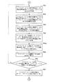
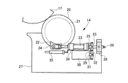
図1A及び図1Bは本発明の一実施例におけるワイピング・ロール駆動モータ及びワイピング・ロール接触圧調整用モータの駆動制御装置のハード・ブロック図、図2A乃至図2Dと図3A乃至図3Dは本発明の一実施例におけるワイピング・ロール駆動モータ及びワイピング・ロール接触圧調整用モータの駆動制御装置の動作フロー図、図4はワイピング装置の接触圧調整機構の側面図、図5はワイピング装置の駆動系を示す平面図、図6は凹版印刷機の全体側面図である。 1A and 1B are hardware block diagrams of a drive control device for a wiping / roll driving motor and a wiping / roll contact pressure adjusting motor according to an embodiment of the present invention. FIGS. 2A to 2D and FIGS. 3A to 3D are books. FIG. 4 is a side view of a contact pressure adjusting mechanism of the wiping device, and FIG. 5 is a drive of the wiping device. FIG. 6 is an overall side view of the intaglio printing press.
図6に示すように、凹版印刷機(印刷機)は、給紙部10と凹版印刷部11と排紙部12とを備え、これらが連接された機械フレーム13の、凹版印刷部11におけるワイピング装置14に対応した部位には、ワイピング装置引出し用の切欠き15が形成されて、ワイピング装置14全体が操作側の機外側方へ引出し可能になっている。
As shown in FIG. 6, the intaglio printing machine (printing machine) includes a
前記凹版印刷部11は、インカーからのインキが着肉ローラ群16より凹版胴(第1の回転体)17に装着した凹版(図示せず)に転移された後、ワイピング装置14により絵柄部分以外のインキが取り除かれて、同凹版胴17と圧胴18との間を通る紙に絵柄部分のインキを転移するようになっている。
The
前記ワイピング装置14は、図4に示すように、ワイピング・ロール(第2の回転体)20が偏心軸受21の内孔で軸支されており、偏心軸受21の外周側に固定された金具22を往復動させることで、ワイピング・ロール20が凹版胴17に着脱するようになっている。
As shown in FIG. 4, the wiping
即ち、ワイピング・ロール着脱用油圧シリンダ23のピストンロッド先端がピン24により金具22に枢着される一方、ヘッド側にはスラストベアリング25を介してネジ軸26が連結されている。スラストベアリング25は、ネジ軸26の軸方向に沿う移動をワイピング・ロール着脱用油圧シリンダ23に伝達するが、ネジ軸26の回転をワイピング・ロール着脱用油圧シリンダ23に伝達することはない。このネジ軸26は洗浄液槽27に固定されたネジ軸受28に螺合している。
That is, the tip of the piston rod of the wiping / roll attaching / detaching
スラストベアリング25を内蔵したブラケット29には、ワイピング・ロール接触圧調整用モータ(接触圧調整モータ)30が固定されている。ワイピング・ロール接触圧調整用モータ30のモータ軸31に固定されたギア32は、ネジ軸26に固定されたギア33に噛合している。一方、ワイピング・ロール着脱用油圧シリンダ23には検出体34が備えられており、この検出体34の位置を検出するために、直動型のポテンショメータ35を備えている。
A wiping / roll contact pressure adjusting motor (contact pressure adjusting motor) 30 is fixed to the
従って、ワイピング・ロール着脱用油圧シリンダ23が伸長作動したときにワイピング・ロール20が凹版胴17に接触し、収縮作動したときにワイピング・ロール20が凹版胴17から離れる。また、ワイピング・ロール20と凹版胴17とが接触している時にワイピング・ロール接触圧調整用モータ30を回転させるとネジ軸26が回転して軸方向に移動するため、これに伴いワイピング・ロール着脱用油圧シリンダ23も移動し、ワイピング・ロール20と凹版胴17との接触圧を調整することができる(接触圧調整機構)。尚、図4はワイピング・ロール20の左側(操作側)を示しているが、ワイピング・ロール20の右側(駆動側)にも上述したのと同じ構成の装置が組み付けられている。
Accordingly, the wiping
図5に示すように、前記ワイピング・ロール接触圧調整用モータ30はワイピング・ロール駆動モータ及びワイピング・ロール接触圧調整用モータの駆動制御装置(制御装置)50により駆動制御され、この駆動制御装置50からの駆動指令で、前記接触時にワイピング・ロール接触圧調整用モータ30が正転すると接触圧が高くなり、逆転すると接触圧が低くなるようになっている。
As shown in FIG. 5, the wiping / roll contact
前記駆動制御装置50は、ワイピング・ロール駆動モータ(第2の回転体駆動用モータ)40を駆動制御すると共に、当該ワイピング・ロール駆動モータ40の電流値(トルク値)に応じて、前記ワイピング・ロール接触圧調整用モータ30を駆動制御するようになっている。
The
また、前記ワイピング・ロール駆動モータ40の出力軸41と、フレーム42にベアリング43を介して支持されたワイピング・ロール20の駆動軸44との間に、カップリング45を介してウォームギア機構からなる減速機46が介装される。
Further, a reduction gear comprising a worm gear mechanism is provided between the
図1A及び図1Bに示すように、駆動制御装置50は、CPU100、ROM101及びRAM102の他に、各入出力装置103〜113及びインタフェース114がBUS(母線)で接続されて構成されている。
As shown in FIGS. 1A and 1B, the
このBUSには、印刷回転速度記憶用メモリM100、ワイピング・ロールの回転速度比記憶用メモリM101、指令回転速度記憶用メモリM102、ワイピング・ロール駆動モータの指令回転速度記憶用メモリM103、原動モータ用ロータリ・エンコーダに接続されたF/V変換器の出力記憶用メモリM104、凹版印刷機の現在の回転速度記憶用メモリM105が接続されている。 This BUS includes a printing rotation speed storage memory M100, a wiping / roll rotation speed ratio storage memory M101, a command rotation speed storage memory M102, a wiping / roll drive motor command rotation speed storage memory M103, and a drive motor An output storage memory M104 of the F / V converter connected to the rotary encoder and a current rotational speed storage memory M105 of the intaglio printing press are connected.
また、BUSには、ワイピング・ロール接触圧調整用モータの現在位置検出用カウンタのカウント値記憶用メモリM106、ワイピング・ロール接触圧調整用モータの現在位置記憶用メモリM107、ワイピング・ロール駆動モータの基準電流値記憶用メモリM108、ワイピング・ロール駆動モータの現在の電流値記憶用メモリM109、ワイピング・ロール駆動モータの現在の電流値の差記憶用メモリM110、ワイピング・ロール駆動モータの現在の電流値の差の絶対値記憶用メモリM111、ワイピング・ロール駆動モータの現在の電流値の差の許容値記憶用メモリM112が接続されている。 The BUS includes a count value storage memory M106 of a current position detection counter of a wiping / roll contact pressure adjusting motor, a current position storage memory M107 of a wiping / roll contact pressure adjusting motor, and a wiping / roll driving motor. Reference current value storage memory M108, current current value storage memory M109 of the wiping / roll driving motor, current storage value difference memory M110 of the wiping / roll driving motor, current current value of the wiping / roll driving motor Are connected to an absolute value storage memory M111 of the difference between them and an allowable value storage memory M112 of the current current difference of the wiping / roll driving motor.
さらに、入出力装置103には、凹版印刷機駆動スイッチ120、凹版印刷機駆動停止スイッチ121、接触圧アップ・スイッチ122、接触圧ダウン・スイッチ123、ワイピング・ロールの接触圧調整完了スイッチ124、キーボードや各種スイッチ及びボタン等の入力装置125、CRTやランプ等の表示器126、及び、フロッピー(登録商標)・ディスクドライブやプリンタ等の出力装置127が接続されている。
Further, the input /
入出力装置104には、印刷回転速度設定器128、ワイピング・ロールの回転速度比設定器129が接続されている。
A printing rotation
入出力装置105には、ワイピング・ロール駆動モータの現在の電流値表示器130、ワイピング・ロール接触圧調整用モータの現在位置表示器131が接続されている。
The input /
入出力装置106には、ワイピング・ロールの接触圧調整準備完了表示用LEDの駆動装置132を介してワイピング・ロールの接触圧調整準備完了表示用LED133が接続されている。
A wiping / roll contact pressure adjustment preparation completion display LED 133 is connected to the input /
入出力装置107には、ワイピング・ロール着脱用油圧シリンダ用駆動装置134を介してワイピング・ロール着脱用油圧シリンダ23が接続されている。
A wiping / roll attaching / detaching
入出力装置108には、D/A変換器136及び原動モータ・ドライバ137を介して原動モータ138が接続されている。
A driving
入出力装置109には、A/D変換器139及びF/V変換器140を介して前記原動モータ138に連結駆動される原動モータ用ロータリ・エンコーダ141が接続されている。また、前記原動モータ用ロータリ・エンコーダ141は、前記原動モータ・ドライバ137に接続されている。
The input /
入出力装置110には、D/A変換器142及びワイピング・ロール駆動モータ・ドライバ143を介してワイピング・ロール駆動モータ40が接続されている。また、前記ワイピング・ロール駆動モータ・ドライバ143には、前記ワイピング・ロール駆動モータ40に連結駆動されるワイピング・ロール駆動モータ用ロータリ・エンコーダ144が接続されている。
A wiping /
入出力装置111には、前記ワイピング・ロール駆動モータ・ドライバ143が接続されて当該モータ・ドライバ143から電流値が出力されるようになっている。
The wiping / roll driving motor /
入出力装置112には、ワイピング・ロール接触圧調整用モータ・ドライバ145を介してワイピング・ロール接触圧調整用モータ30が接続され、前記モータ・ドライバ145へ正転指令又は逆転指令が出力されるようになっている。
A wiping / roll contact
入出力装置113には、ワイピング・ロール接触圧調整用モータの現在位置検出用カウンタ146を介して前記ワイピング・ロール接触圧調整用モータ30に連結駆動されるワイピング・ロール接触圧調整用モータ用ロータリ・エンコーダ147が接続されている。
The input /
そして、インタフェース114には、給紙部10と凹版印刷部11が接続されている。
The
以下に、上述したワイピング・ロール駆動モータ及びワイピング・ロール接触圧調整用モータの駆動制御装置50の動作について説明する。
The operation of the
駆動制御装置50は、図2A乃至図2Dと図3A乃至図3Dに示す動作フローにしたがって動作する。
The
即ち、ステップP1で印刷回転速度設定器128に、印刷回転速度入力が有ったか否かを判断し、可であればステップP2で印刷回転速度設定器128より、印刷回転速度を読込みメモリM100に記憶する一方、否であれば直にステップP3に移行する。
That is, in step P1, it is determined whether or not the printing rotation
次に、ステップP3でワイピング・ロールの回転速度比設定器129に、ワイピング・ロールの回転速度比入力が有ったか否かを判断し、可であればステップP4でワイピング・ロールの回転速度比設定器129より、ワイピング・ロールの回転速度比を読込みメモリM101に記憶する一方、否であれば直にステップP5に移行する。
Next, in step P3, it is determined whether or not the wiping roll rotational
次に、ステップP5で凹版印刷機駆動スイッチ120がONされたか否かを判断し、可であればステップP6でワイピング・ロール着脱用油圧シリンダ用駆動装置134に、着指令を出力する一方、否であればステップP1に戻る。
Next, in step P5, it is determined whether or not the intaglio printing
次に、ステップP7で給紙部10に、給紙開始指令を出力した後、ステップP8で凹版印刷部11に、印刷開始指令を出力する。次いでステップP9で印刷回転速度をメモリM100から読込む。
Next, after a paper feed start command is output to the
次に、ステップP10で指令回転速度記憶用メモリM102に、印刷回転速度を上書きした後、ステップP11で指令回転速度をメモリM102から読込む。次いでステップP12でワイピング・ロールの回転速度比をメモリM101から読込む。 Next, after the printing rotational speed is overwritten in the command rotational speed storage memory M102 in step P10, the command rotational speed is read from the memory M102 in step P11. In step P12, the rotational speed ratio of the wiping roll is read from the memory M101.
次に、ステップP13で指令回転速度にワイピング・ロールの回転速度比を乗算し、ワイピング・ロール駆動モータ40の指令回転速度を演算してメモリM103に記憶した後、ステップP14で指令回転速度をメモリM102から読込む。
Next, in step P13, the command rotational speed is multiplied by the rotational speed ratio of the wiping / roll, the command rotational speed of the wiping /
次に、ステップP15で原動モータ・ドライバ137に、D/A変換器136を介して指令回転速度を出力した後、ステップP16でワイピング・ロール駆動モータ40の指令回転速度をメモリM103から読込む。次いでステップP17でワイピング・ロール駆動モータ・ドライバ143に、D/A変換器142を介してワイピング・ロール駆動モータ40の指令回転速度を出力する。
Next, in step P15, the command rotational speed is output to the driving
次に、ステップP18で原動モータ用ロータリ・エンコーダ141に接続されたF/V変換器140より、A/D変換器139を介してその出力を読込んでメモリM104に記憶した後、ステップP19で原動モータ用ロータリ・エンコーダ141に接続されたF/V変換器140の出力より、凹版印刷機の現在の回転速度を演算してメモリM105に記憶する。
Next, in step P18, the output is read from the F /
次に、ステップP20で指令回転速度をメモリM102から読込んだ後、ステップP21で凹版印刷機の現在の回転速度=指令回転速度か否かを判断し、可であればステップP22でワイピング・ロールの接触圧調整準備完了表示用LEDの駆動装置132に、点灯指令を出力する一方、否であればステップP14に戻る。
Next, in step P20, the command rotational speed is read from the memory M102, and then in step P21, it is determined whether or not the current rotational speed of the intaglio printing machine is equal to the command rotational speed. The lighting command is output to the
次に、ステップP23で接触圧アップ・スイッチ122がONされたか否かを判断し、可であればステップP24でワイピング・ロール接触圧調整用モータ・ドライバ145に、正転指令を出力する一方、否であれば後述するステップP32に移行する。
Next, in step P23, it is determined whether or not the contact pressure up
次に、ステップP25でワイピング・ロール接触圧調整用モータの現在位置検出用カウンタ146より、カウント値を読込んでメモリM106に記憶した後、ステップP26でワイピング・ロール接触圧調整用モータの現在位置検出用カウンタ146のカウント値より、ワイピング・ロール接触圧調整用モータ30の現在位置を演算してメモリM107に記憶する。
Next, in step P25, the count value is read from the current
次に、ステップP27でワイピング・ロール接触圧調整用モータの現在位置表示器131に、ワイピング・ロール接触圧調整用モータ30の現在位置を表示した後、ステップP28でワイピング・ロール駆動モータ・ドライバ143より、電流値を読込んでワイピング・ロール駆動モータの現在の電流値記憶用メモリM109に記憶する。
Next, after the current position of the wiping / roll contact
次に、ステップP29でワイピング・ロール駆動モータの現在の電流値表示器130に、ワイピング・ロール駆動モータ40の現在の電流値を表示した後、ステップP30で接触圧アップ・スイッチ122がOFFされたか否かを判断し、可であればステップP31でワイピング・ロール接触圧調整用モータ・ドライバ145への正転指令出力を停止する一方、否であればステップP25に戻る。
Next, after displaying the current value of the wiping /
次に、前述したステップP32で接触圧ダウン・スイッチ123がONされたか否かを判断し、可であればステップP33でワイピング・ロール接触圧調整用モータ・ドライバ145に、逆転指令を出力する一方、否であれば後述するステップP41に移行する。
Next, it is determined whether or not the contact pressure down
次に、ステップP34でワイピング・ロール接触圧調整用モータの現在位置検出用カウンタ146より、カウント値を読込んでメモリM106に記憶した後、ステップP35でワイピング・ロール接触圧調整用モータの現在位置検出用カウンタ146のカウント値より、ワイピング・ロール接触圧調整用モータ30の現在位置を演算してメモリM107に記憶する。
Next, in step P34, the count value is read from the current
次に、ステップP36でワイピング・ロール接触圧調整用モータの現在位置表示器131に、ワイピング・ロール接触圧調整用モータ30の現在位置を表示した後、ステップP37でワイピング・ロール駆動モータ・ドライバ143より、電流値を読込んでワイピング・ロール駆動モータの現在の電流値記憶用メモリM109に記憶する。
Next, after the current position of the wiping / roll contact
次に、ステップP38でワイピング・ロール駆動モータの現在の電流値表示器130に、ワイピング・ロール駆動モータ40の現在の電流値を表示した後、ステップP39で接触圧ダウン・スイッチ123がOFFされたか否かを判断し、可であればステップP40でワイピング・ロール接触圧調整用モータ・ドライバ145への逆転指令出力を停止する一方、否であればステップP34に戻る。
Next, in step P38, the current value of the wiping /
次に、ステップP41でワイピング・ロールの接触圧調整完了スイッチ124が、ONされたか否かを判断し、可であればステップP42でワイピング・ロール駆動モータ・ドライバ143より、電流値を読込んでワイピング・ロール駆動モータの基準電流値記憶用メモリM108に記憶した後、ステップP43でワイピング・ロールの接触圧調整準備完了表示用LEDの駆動装置132への点灯指令出力を停止する一方、否であればステップP23に戻る。
Next, in step P41, it is determined whether or not the wiping / roll contact pressure
以上の動作フローにより、オペレータの目視及び操作下で、凹版胴17にワイピング・ロール20が最適な接触圧で着した時のワイピング・ロール駆動モータ40の基準電流値が設定される。
With the above-described operation flow, the reference current value of the wiping /
次に、ステップP44で凹版印刷機駆動停止スイッチ121がONされたか否かを判断し、可であればステップP45で給紙部10に、給紙停止指令を出力した後、ステップP46で凹版印刷部11に、印刷停止指令を出力する。次いでステップP47でワイピング・ロール着脱用油圧シリンダ用駆動装置134に、脱指令を出力した後、ステップP48で原動モータ・ドライバ137に、停止指令を出力する。最後に、ステップP49でワイピング・ロール駆動モータ・ドライバ143に、停止指令を出力する。
Next, in step P44, it is determined whether or not the intaglio printing press
一方、前記ステップP44で否であれば、ステップP50でワイピング・ロール駆動モータ・ドライバ143より、電流値を読込んでワイピング・ロール駆動モータの現在の電流値記憶用メモリM109に記憶した後、ステップP51でワイピング・ロール駆動モータの現在の電流値表示器130に、ワイピング・ロール駆動モータ40の現在の電流値を表示する。
On the other hand, if the result is NO in step P44, the current value is read from the wiping / roll driving
次に、ステップP52でワイピング・ロール駆動モータ40の基準電流値をメモリM108から読込んだ後、ステップP53でワイピング・ロール駆動モータ40の現在の電流値よりワイピング・ロール駆動モータ40の基準電流値を減算し、ワイピング・ロール駆動モータ40の現在の電流値の差を演算してメモリM110に記憶する。
Next, after reading the reference current value of the wiping /
次に、ステップP54でワイピング・ロール駆動モータ40の現在の電流値の差より、ワイピング・ロール駆動モータ40の現在の電流値の差の絶対値を演算してメモリM111に記憶した後、ステップP55でワイピング・ロール駆動モータ40の現在の電流値の差の許容値をメモリM112から読込む。
Next, in step P54, the absolute value of the difference in the current value of the wiping /
次に、ステップP56でワイピング・ロール駆動モータの現在の電流値の差の絶対値≦ワイピング・ロール駆動モータの現在の電流値の差の許容値か否かを判断し、可であればステップP44に戻る一方、否であればステップP57でワイピング・ロール駆動モータ40の現在の電流値をメモリM109から読込む。
Next, in step P56, it is determined whether or not the absolute value of the current difference between the current values of the wiping and roll drive motors is equal to or smaller than the allowable value of the current difference between the current values of the wiping and roll drive motors. On the other hand, if NO, the current value of the wiping /
次に、ステップP58でワイピング・ロール駆動モータ40の基準電流値をメモリM108から読込んだ後、ステップP59でワイピング・ロール駆動モータの現在の電流値>ワイピング・ロール駆動モータの基準電流値か否かを判断する。
Next, in step P58, the reference current value of the wiping / rolling
次に、前記ステップP59で可であれば、ステップP60でワイピング・ロール接触圧調整用モータ・ドライバ145に、逆転指令を出力した後、ステップP61でワイピング・ロール接触圧調整用モータの現在位置検出用カウンタ146より、カウント値を読込んでメモリM106に記憶する。
If yes in step P59, a reverse rotation command is output to the wiping / roll contact pressure adjusting
次に、ステップP62でワイピング・ロール接触圧調整用モータの現在位置検出用カウンタ146のカウント値より、ワイピング・ロール接触圧調整用モータ30の現在位置を演算してメモリM107に記憶した後、ステップP63でワイピング・ロール接触圧調整用モータの現在位置表示器131に、ワイピング・ロール接触圧調整用モータ30の現在位置を表示する。
Next, in step P62, the current position of the wiping / roll contact
次に、ステップP64でワイピング・ロール駆動モータ・ドライバ143より、電流値を読込んでワイピング・ロール駆動モータの現在の電流値記憶用メモリM109に記憶した後、ステップP64aでワイピング・ロール駆動モータの現在の電流値表示器130に、ワイピング・ロール駆動モータ40の現在の電流値を表示する。次いで、ステップP65でワイピング・ロール駆動モータ40の基準電流値をメモリM108から読込む。
Next, in step P64, the current value is read from the wiping / roll driving
次に、ステップP66でワイピング・ロール駆動モータの現在の電流値=ワイピング・ロール駆動モータの基準電流値か否かを判断し、可であればステップP67でワイピング・ロール接触圧調整用モータ・ドライバ145への逆転指令出力を停止してステップP44に戻る一方、否であればステップP61に戻る。 Next, in step P66, it is determined whether or not the current value of the wiping / roll driving motor is equal to the reference current value of the wiping / roll driving motor. If yes, the wiping / roll contact pressure adjusting motor driver is determined in step P67. While the reverse rotation command output to 145 is stopped and the process returns to step P44, if NO, the process returns to step P61.
一方、前記ステップP59で否であれば、ステップP68でワイピング・ロール接触圧調整用モータ・ドライバ145に、正転指令を出力した後、ステップP69でワイピング・ロール接触圧調整用モータの現在位置検出用カウンタ146より、カウント値を読込んでメモリM106に記憶する。
On the other hand, if NO in step P59, a normal rotation command is output to the wiping / roll contact pressure adjusting
次に、ステップP70でワイピング・ロール接触圧調整用モータの現在位置検出用カウンタ146のカウント値より、ワイピング・ロール接触圧調整用モータ30の現在位置を演算してメモリM107に記憶した後、ステップP71でワイピング・ロール接触圧調整用モータの現在位置表示器131に、ワイピング・ロール接触圧調整用モータ30の現在位置を表示する。
Next, in step P70, the current position of the wiping / roll contact
次に、ステップP72でワイピング・ロール駆動モータ・ドライバ143より、電流値を読込んでワイピング・ロール駆動モータの現在の電流値記憶用メモリM109に記憶した後、ワイピング・ロール駆動モータの現在の電流値表示器130に、ワイピング・ロール駆動モータ40の現在の電流値を表示する。次いで、ステップP73でワイピング・ロール駆動モータ40の基準電流値をメモリM108から読込む。
Next, in step P72, the current value is read from the wiping roll
次に、ステップP74でワイピング・ロール駆動モータの現在の電流値=ワイピング・ロール駆動モータの基準電流値か否かを判断し、可であればステップP75でワイピング・ロール接触圧調整用モータ・ドライバ145への正転指令出力を停止してステップP44に戻る一方、否であればステップP69に戻る。 Next, in step P74, it is determined whether or not the current value of the wiping / roll driving motor is equal to the reference current value of the wiping / roll driving motor. If yes, the wiping / roll contact pressure adjusting motor driver is determined in step P75. The forward rotation command output to 145 is stopped and the process returns to step P44. If not, the process returns to step P69.
以上の動作フローにより、凹版印刷機の定常運転時には、凹版胴17にワイピング・ロール20が常に最適な接触圧で着するようにワイピング・ロール接触圧調整用モータ30が自動で駆動制御される。
With the above operation flow, during the steady operation of the intaglio printing press, the wiping / roll contact
このように本実施例では、凹版胴17に対するワイピング・ロール20の接触圧(負荷)をワイピング・ロール駆動モータ40のトルク値(電流値)に換算し、これをワイピング・ロール接触圧調整用モータ30にフィードバックするようにしたので、機械的振動(ノイズ等の外乱)の影響を受けることなく、前記接触圧を自動でかつ常に高精度に調整することができる。
Thus, in this embodiment, the contact pressure (load) of the wiping
また、本実施例では、ワイピング・ロール駆動モータ40とワイピング・ロール20間の駆動系にウォームギア機構からなる減速機46を介装したので、減速機46内のバックラッシュで機械的振動(負荷変動)を吸収することができ、特に、ウォームギア機構はワイピング・ロール20側からの機械的振動(負荷振動)をワイピング・ロール駆動モータ40側へ伝達し難いため、より一層安定して長期的な負荷変動のみを効果的に検出可能となるという利点が得られる。
Further, in this embodiment, since a
尚、本発明は上記実施例に限定されず、本発明の要旨を逸脱しない範囲で各種変更が可能であることはいうまでもない。また、本発明は、単独駆動されるインキ・ツボ・ロールと位置調整が可能なパターン・ロールとの接触圧調整にも適用することができる。 Needless to say, the present invention is not limited to the above embodiments, and various modifications can be made without departing from the scope of the present invention. The present invention can also be applied to contact pressure adjustment between an independently driven ink fountain roll and a pattern roll capable of position adjustment.
本発明は、凹版印刷機等印刷機の接触圧調整方法及び接触圧調整装置に適用可能である。 The present invention is applicable to a contact pressure adjusting method and a contact pressure adjusting device for a printing press such as an intaglio printing press.
10 給紙部
11 凹版印刷部
14 ワイピング装置
17 凹版胴
20 ワイピング・ロール
23 ワイピング・ロール着脱用油圧シリンダ
30 ワイピング・ロール接触圧調整用モータ
40 ワイピング・ロール駆動モータ
46 減速機
50 ワイピング・ロール駆動モータ及びワイピング・ロール接触圧調整用モータの駆動制御装置
130 ワイピング・ロール駆動モータの現在の電流値表示器
131 ワイピング・ロール接触圧調整用モータの現在位置表示器
143 ワイピング・ロール駆動モータ・ドライバ
144 ワイピング・ロール駆動モータ用ロータリ・エンコーダ
145 ワイピング・ロール接触圧調整用モータ・ドライバ
147 ワイピング・ロール接触圧調整用モータ用ロータリ・エンコーダ
DESCRIPTION OF
Claims (6)
前記第1の回転体に対接する第2の回転体と、
前記第2の回転体を回転駆動する為の第2の回転体駆動用モータと、
前記第1の回転体に対する前記第2の回転体の接触圧を調整する為の接触圧調整機構と、
前記接触圧調整機構を駆動する接触圧調整モータと、
を備えた印刷機の接触圧調整方法において、
前記第2の回転体駆動用モータを駆動するトルク値に応じて、前記接触圧調整モータを駆動すること、
を特徴とする印刷機の接触圧調整方法。 A first rotating body;
A second rotating body in contact with the first rotating body;
A second rotating body driving motor for rotationally driving the second rotating body;
A contact pressure adjusting mechanism for adjusting a contact pressure of the second rotating body with respect to the first rotating body;
A contact pressure adjusting motor for driving the contact pressure adjusting mechanism;
In the contact pressure adjustment method of a printing press equipped with
Driving the contact pressure adjusting motor according to a torque value for driving the second rotating body driving motor;
A method for adjusting the contact pressure of a printing press.
前記第1の回転体に対接する第2の回転体と、
前記第2の回転体を回転駆動する為の第2の回転体駆動用モータと、
前記第1の回転体に対する前記第2の回転体の接触圧を調整する為の接触圧調整機構と、
前記接触圧調整機構を駆動する接触圧調整モータと、
を備えた印刷機の接触圧調整装置において、
前記第2の回転体駆動用モータを駆動するトルク値に応じて、前記接触圧調整モータを駆動する制御装置を備えたこと、
を特徴とする印刷機の接触圧調整装置。 A first rotating body;
A second rotating body in contact with the first rotating body;
A second rotating body driving motor for rotationally driving the second rotating body;
A contact pressure adjusting mechanism for adjusting a contact pressure of the second rotating body with respect to the first rotating body;
A contact pressure adjusting motor for driving the contact pressure adjusting mechanism;
In a contact pressure adjusting device of a printing press equipped with
A controller for driving the contact pressure adjusting motor according to a torque value for driving the second rotating body driving motor;
A contact pressure adjusting device for a printing press.
Priority Applications (6)
| Application Number | Priority Date | Filing Date | Title |
|---|---|---|---|
| JP2010128572A JP2011251504A (en) | 2010-06-04 | 2010-06-04 | Contact pressure adjusting method and contact pressure adjusting apparatus for printing machine |
| CN201110145186.6A CN102267276B (en) | 2010-06-04 | 2011-05-31 | The contact method of adjustment of printing machine and contact adjusting device |
| CN201510455294.1A CN105150668A (en) | 2010-06-04 | 2011-05-31 | Contact pressure adjusting method and contact pressure adjusting apparatus for printing press |
| US13/152,951 US9132624B2 (en) | 2010-06-04 | 2011-06-03 | Contact pressure adjusting method and contact pressure adjusting apparatus for printing press |
| EP20110168747 EP2392461B1 (en) | 2010-06-04 | 2011-06-06 | Contact pressure adjusting method and contact pressure adjusting apparatus for printing press |
| US14/818,032 US20150336376A1 (en) | 2010-06-04 | 2015-08-04 | Contact pressure adjusting method and contact pressure adjusting apparatus for printing press |
Applications Claiming Priority (1)
| Application Number | Priority Date | Filing Date | Title |
|---|---|---|---|
| JP2010128572A JP2011251504A (en) | 2010-06-04 | 2010-06-04 | Contact pressure adjusting method and contact pressure adjusting apparatus for printing machine |
Publications (2)
| Publication Number | Publication Date |
|---|---|
| JP2011251504A true JP2011251504A (en) | 2011-12-15 |
| JP2011251504A5 JP2011251504A5 (en) | 2013-07-18 |
Family
ID=45415842
Family Applications (1)
| Application Number | Title | Priority Date | Filing Date |
|---|---|---|---|
| JP2010128572A Pending JP2011251504A (en) | 2010-06-04 | 2010-06-04 | Contact pressure adjusting method and contact pressure adjusting apparatus for printing machine |
Country Status (1)
| Country | Link |
|---|---|
| JP (1) | JP2011251504A (en) |
Cited By (2)
| Publication number | Priority date | Publication date | Assignee | Title |
|---|---|---|---|---|
| JP2016537225A (en) * | 2013-11-21 | 2016-12-01 | ケーニツヒ ウント バウエル アクチエンゲゼルシヤフトKoenig & Bauer AG | Intaglio printing machine and printing facility equipped with intaglio printing machine |
| US10124572B2 (en) | 2014-09-17 | 2018-11-13 | Komori Corporation | Method and device for adjusting contact pressure of intaglio printer wiping roller |
Citations (5)
| Publication number | Priority date | Publication date | Assignee | Title |
|---|---|---|---|---|
| JPS58108147A (en) * | 1981-12-08 | 1983-06-28 | ハイデルベルガ−・ドルツクマシ−ネン・アクチエンゲゼルシヤフト | Method and device for reducing error of register in polychrome rotary press |
| JPH0437542A (en) * | 1990-06-01 | 1992-02-07 | Komori Corp | Wiping device of intaglio printer |
| JPH09193337A (en) * | 1996-01-24 | 1997-07-29 | Komori Corp | Apparatus for adjusting contact pressure of printer |
| JPH11159587A (en) * | 1997-11-28 | 1999-06-15 | Koyo Seiko Co Ltd | Belt tensioner mechanism |
| JP2005007628A (en) * | 2003-06-17 | 2005-01-13 | National Printing Bureau | Method for automatically controlling wiping roller of intaglio printing machine and automatic controlling device |
-
2010
- 2010-06-04 JP JP2010128572A patent/JP2011251504A/en active Pending
Patent Citations (5)
| Publication number | Priority date | Publication date | Assignee | Title |
|---|---|---|---|---|
| JPS58108147A (en) * | 1981-12-08 | 1983-06-28 | ハイデルベルガ−・ドルツクマシ−ネン・アクチエンゲゼルシヤフト | Method and device for reducing error of register in polychrome rotary press |
| JPH0437542A (en) * | 1990-06-01 | 1992-02-07 | Komori Corp | Wiping device of intaglio printer |
| JPH09193337A (en) * | 1996-01-24 | 1997-07-29 | Komori Corp | Apparatus for adjusting contact pressure of printer |
| JPH11159587A (en) * | 1997-11-28 | 1999-06-15 | Koyo Seiko Co Ltd | Belt tensioner mechanism |
| JP2005007628A (en) * | 2003-06-17 | 2005-01-13 | National Printing Bureau | Method for automatically controlling wiping roller of intaglio printing machine and automatic controlling device |
Cited By (2)
| Publication number | Priority date | Publication date | Assignee | Title |
|---|---|---|---|---|
| JP2016537225A (en) * | 2013-11-21 | 2016-12-01 | ケーニツヒ ウント バウエル アクチエンゲゼルシヤフトKoenig & Bauer AG | Intaglio printing machine and printing facility equipped with intaglio printing machine |
| US10124572B2 (en) | 2014-09-17 | 2018-11-13 | Komori Corporation | Method and device for adjusting contact pressure of intaglio printer wiping roller |
Similar Documents
| Publication | Publication Date | Title |
|---|---|---|
| US5125339A (en) | Apparatus for displacing shaft-mounting bearing stands | |
| US8069786B2 (en) | Printing groups comprising at least two cooperating cylinders and radially movable bearing units | |
| JPH0885196A (en) | Offset press | |
| EP0694384A2 (en) | Cylinder throw-on and throw-off mechanism for printing press | |
| JP3423627B2 (en) | Rotary printing press | |
| US6289805B1 (en) | Device and method for driving a printing cylinder | |
| US20020005127A1 (en) | Printing press | |
| JP2011251504A (en) | Contact pressure adjusting method and contact pressure adjusting apparatus for printing machine | |
| JP5498349B2 (en) | Contact pressure adjusting method and contact pressure adjusting device for intaglio printing press | |
| US6498445B2 (en) | Oscillation apparatus for oscillating roller | |
| EP3196019B1 (en) | Method and device for adjusting contact pressure of intaglio printer wiping roller | |
| CN208930909U (en) | A kind of pressure regulation of interchangeable roller full rotating wheel printing machine and combined pressure device | |
| CN210390422U (en) | Radial online speed regulation printing device | |
| EP1314560B1 (en) | Printing press | |
| JP2011251505A (en) | Method and device for adjusting contact pressure of printing press | |
| JP4190889B2 (en) | How to drive a printing unit | |
| US20150336376A1 (en) | Contact pressure adjusting method and contact pressure adjusting apparatus for printing press | |
| EP1795350B1 (en) | Ink transport route switching method and apparatus in inking device of printing press | |
| JP5629550B2 (en) | Contact pressure adjusting method and contact pressure adjusting device for intaglio printing press | |
| JP6399647B2 (en) | Method and apparatus for adjusting contact pressure of wiping roller of intaglio printing press | |
| CN108839423A (en) | A kind of pressure regulation of interchangeable roller full rotating wheel printing machine and combined pressure device | |
| JPH0734670Y2 (en) | Nip pressure adjustment mechanism | |
| JP2537504Y2 (en) | Drive stopping device for inking device in printing press | |
| JP2007509780A (en) | Inca drive shaftless unit | |
| JPH08118588A (en) | Device for supporting plate cylinder |
Legal Events
| Date | Code | Title | Description |
|---|---|---|---|
| A521 | Written amendment |
Free format text: JAPANESE INTERMEDIATE CODE: A523 Effective date: 20130603 |
|
| A621 | Written request for application examination |
Free format text: JAPANESE INTERMEDIATE CODE: A621 Effective date: 20130603 |
|
| A977 | Report on retrieval |
Free format text: JAPANESE INTERMEDIATE CODE: A971007 Effective date: 20140122 |
|
| A131 | Notification of reasons for refusal |
Free format text: JAPANESE INTERMEDIATE CODE: A131 Effective date: 20140204 |
|
| A02 | Decision of refusal |
Free format text: JAPANESE INTERMEDIATE CODE: A02 Effective date: 20140610 |