JP2011240407A - Method and device for continuously detecting slag level in electroslag remelting apparatus with short slidable mold - Google Patents
Method and device for continuously detecting slag level in electroslag remelting apparatus with short slidable mold Download PDFInfo
- Publication number
- JP2011240407A JP2011240407A JP2011105826A JP2011105826A JP2011240407A JP 2011240407 A JP2011240407 A JP 2011240407A JP 2011105826 A JP2011105826 A JP 2011105826A JP 2011105826 A JP2011105826 A JP 2011105826A JP 2011240407 A JP2011240407 A JP 2011240407A
- Authority
- JP
- Japan
- Prior art keywords
- level
- electroslag remelting
- slag bath
- radar
- slag
- Prior art date
- Legal status (The legal status is an assumption and is not a legal conclusion. Google has not performed a legal analysis and makes no representation as to the accuracy of the status listed.)
- Granted
Links
- 239000002893 slag Substances 0.000 title claims abstract description 61
- 238000000034 method Methods 0.000 title claims abstract description 21
- 239000000523 sample Substances 0.000 claims abstract description 29
- 238000011156 evaluation Methods 0.000 claims abstract description 6
- 239000007788 liquid Substances 0.000 claims description 33
- 238000005259 measurement Methods 0.000 claims description 31
- 230000001681 protective effect Effects 0.000 claims description 10
- 238000005266 casting Methods 0.000 claims description 6
- 238000011978 dissolution method Methods 0.000 claims 1
- 230000001678 irradiating effect Effects 0.000 abstract 1
- 229910052751 metal Inorganic materials 0.000 description 7
- 239000002184 metal Substances 0.000 description 7
- 230000005856 abnormality Effects 0.000 description 4
- 229910000595 mu-metal Inorganic materials 0.000 description 3
- XEEYBQQBJWHFJM-UHFFFAOYSA-N Iron Chemical compound [Fe] XEEYBQQBJWHFJM-UHFFFAOYSA-N 0.000 description 2
- PXHVJJICTQNCMI-UHFFFAOYSA-N Nickel Chemical compound [Ni] PXHVJJICTQNCMI-UHFFFAOYSA-N 0.000 description 2
- 238000007654 immersion Methods 0.000 description 2
- 238000010926 purge Methods 0.000 description 2
- RYGMFSIKBFXOCR-UHFFFAOYSA-N Copper Chemical compound [Cu] RYGMFSIKBFXOCR-UHFFFAOYSA-N 0.000 description 1
- ZOKXTWBITQBERF-UHFFFAOYSA-N Molybdenum Chemical compound [Mo] ZOKXTWBITQBERF-UHFFFAOYSA-N 0.000 description 1
- 229910000831 Steel Inorganic materials 0.000 description 1
- 230000000903 blocking effect Effects 0.000 description 1
- 239000010941 cobalt Substances 0.000 description 1
- 229910017052 cobalt Inorganic materials 0.000 description 1
- GUTLYIVDDKVIGB-UHFFFAOYSA-N cobalt atom Chemical compound [Co] GUTLYIVDDKVIGB-UHFFFAOYSA-N 0.000 description 1
- 238000012790 confirmation Methods 0.000 description 1
- 238000007796 conventional method Methods 0.000 description 1
- 239000000498 cooling water Substances 0.000 description 1
- 229910052802 copper Inorganic materials 0.000 description 1
- 239000010949 copper Substances 0.000 description 1
- 230000007423 decrease Effects 0.000 description 1
- 238000010586 diagram Methods 0.000 description 1
- 230000000694 effects Effects 0.000 description 1
- 230000005672 electromagnetic field Effects 0.000 description 1
- 238000000605 extraction Methods 0.000 description 1
- 229910052742 iron Inorganic materials 0.000 description 1
- 229910001092 metal group alloy Inorganic materials 0.000 description 1
- 229910052750 molybdenum Inorganic materials 0.000 description 1
- 239000011733 molybdenum Substances 0.000 description 1
- 229910052759 nickel Inorganic materials 0.000 description 1
- 230000035699 permeability Effects 0.000 description 1
- 238000011160 research Methods 0.000 description 1
- 239000010959 steel Substances 0.000 description 1
- 238000012795 verification Methods 0.000 description 1
- 238000011179 visual inspection Methods 0.000 description 1
Images

Classifications
-
- B—PERFORMING OPERATIONS; TRANSPORTING
- B22—CASTING; POWDER METALLURGY
- B22D—CASTING OF METALS; CASTING OF OTHER SUBSTANCES BY THE SAME PROCESSES OR DEVICES
- B22D2/00—Arrangement of indicating or measuring devices, e.g. for temperature or viscosity of the fused mass
- B22D2/003—Arrangement of indicating or measuring devices, e.g. for temperature or viscosity of the fused mass for the level of the molten metal
-
- B—PERFORMING OPERATIONS; TRANSPORTING
- B22—CASTING; POWDER METALLURGY
- B22D—CASTING OF METALS; CASTING OF OTHER SUBSTANCES BY THE SAME PROCESSES OR DEVICES
- B22D11/00—Continuous casting of metals, i.e. casting in indefinite lengths
- B22D11/16—Controlling or regulating processes or operations
- B22D11/18—Controlling or regulating processes or operations for pouring
- B22D11/181—Controlling or regulating processes or operations for pouring responsive to molten metal level or slag level
-
- B—PERFORMING OPERATIONS; TRANSPORTING
- B22—CASTING; POWDER METALLURGY
- B22D—CASTING OF METALS; CASTING OF OTHER SUBSTANCES BY THE SAME PROCESSES OR DEVICES
- B22D11/00—Continuous casting of metals, i.e. casting in indefinite lengths
- B22D11/16—Controlling or regulating processes or operations
- B22D11/20—Controlling or regulating processes or operations for removing cast stock
- B22D11/201—Controlling or regulating processes or operations for removing cast stock responsive to molten metal level or slag level
-
- B—PERFORMING OPERATIONS; TRANSPORTING
- B22—CASTING; POWDER METALLURGY
- B22D—CASTING OF METALS; CASTING OF OTHER SUBSTANCES BY THE SAME PROCESSES OR DEVICES
- B22D23/00—Casting processes not provided for in groups B22D1/00 - B22D21/00
- B22D23/06—Melting-down metal, e.g. metal particles, in the mould
- B22D23/10—Electroslag casting
-
- C—CHEMISTRY; METALLURGY
- C22—METALLURGY; FERROUS OR NON-FERROUS ALLOYS; TREATMENT OF ALLOYS OR NON-FERROUS METALS
- C22B—PRODUCTION AND REFINING OF METALS; PRETREATMENT OF RAW MATERIALS
- C22B9/00—General processes of refining or remelting of metals; Apparatus for electroslag or arc remelting of metals
- C22B9/16—Remelting metals
- C22B9/18—Electroslag remelting
-
- G—PHYSICS
- G01—MEASURING; TESTING
- G01F—MEASURING VOLUME, VOLUME FLOW, MASS FLOW OR LIQUID LEVEL; METERING BY VOLUME
- G01F23/00—Indicating or measuring liquid level or level of fluent solid material, e.g. indicating in terms of volume or indicating by means of an alarm
- G01F23/22—Indicating or measuring liquid level or level of fluent solid material, e.g. indicating in terms of volume or indicating by means of an alarm by measuring physical variables, other than linear dimensions, pressure or weight, dependent on the level to be measured, e.g. by difference of heat transfer of steam or water
- G01F23/28—Indicating or measuring liquid level or level of fluent solid material, e.g. indicating in terms of volume or indicating by means of an alarm by measuring physical variables, other than linear dimensions, pressure or weight, dependent on the level to be measured, e.g. by difference of heat transfer of steam or water by measuring the variations of parameters of electromagnetic or acoustic waves applied directly to the liquid or fluent solid material
- G01F23/284—Electromagnetic waves
-
- G—PHYSICS
- G01—MEASURING; TESTING
- G01S—RADIO DIRECTION-FINDING; RADIO NAVIGATION; DETERMINING DISTANCE OR VELOCITY BY USE OF RADIO WAVES; LOCATING OR PRESENCE-DETECTING BY USE OF THE REFLECTION OR RERADIATION OF RADIO WAVES; ANALOGOUS ARRANGEMENTS USING OTHER WAVES
- G01S13/00—Systems using the reflection or reradiation of radio waves, e.g. radar systems; Analogous systems using reflection or reradiation of waves whose nature or wavelength is irrelevant or unspecified
- G01S13/88—Radar or analogous systems specially adapted for specific applications
Landscapes
- Engineering & Computer Science (AREA)
- Physics & Mathematics (AREA)
- Mechanical Engineering (AREA)
- Electromagnetism (AREA)
- Remote Sensing (AREA)
- Radar, Positioning & Navigation (AREA)
- Chemical & Material Sciences (AREA)
- General Physics & Mathematics (AREA)
- Manufacturing & Machinery (AREA)
- Materials Engineering (AREA)
- Metallurgy (AREA)
- Organic Chemistry (AREA)
- Fluid Mechanics (AREA)
- Thermal Sciences (AREA)
- Computer Networks & Wireless Communication (AREA)
- Continuous Casting (AREA)
- Furnace Details (AREA)
- Measurement Of Levels Of Liquids Or Fluent Solid Materials (AREA)
- Manufacture And Refinement Of Metals (AREA)
Abstract
Description
エレクトロスラグ再溶解装置(「ESR装置」と称されることもある)で使用される短い水冷式のスライド可能なモールド(鋳型)では、装置に過度の熱負荷やダメージが加わらないように、スラグライン(スラグの液面)のレベル(高さ)、すなわち、溶融金属ライン(溶融金属の液面)のレベルを、当該水冷式のモールドの上縁部に対してほぼ一定に保持する必要がある。これは、装置の種類にもよるが、再溶解によって得られた鋳造体を、再溶解量に応じて、固定位置に配置されたモールドから下方に連続的にまたは段階的に引き抜くことで達成される。固定されたベースプレート(底板)に鋳造体が形成される場合には、モールドは上方に引き上げられる。いずれにしろ、鋳造体は、その表面とモールドの壁との間で相対的な運動を生じながら、モールドから下に引き出されることになる。 In short water-cooled slidable molds (molds) used in electroslag remelting equipment (sometimes called "ESR equipment"), slag is used to prevent excessive heat load and damage to the equipment. It is necessary to keep the level (height) of the line (slag liquid level), that is, the level of the molten metal line (molten metal liquid level) substantially constant with respect to the upper edge of the water-cooled mold. . Depending on the type of equipment, this can be achieved by pulling the cast body obtained by remelting continuously or stepwise downward from the mold placed at the fixed position, depending on the amount of remelting. The When the cast body is formed on the fixed base plate (bottom plate), the mold is pulled upward. In any case, the casting will be pulled down from the mold, causing relative movement between its surface and the mold wall.
エレクトロスラグ再溶解法では、一般的な再溶解速度に基づいて溶融金属から鋳造体を凝固させた場合、鋳造体の成長率は、直径300mm以下の小型の鋳造体で10〜15mm/分、直径1000mm以上の大型の鋳造体で1.5〜3mm/分である。したがって、開放型の再溶解装置、すなわち、蓋のない再溶解装置の場合、目視しつつ、予め所定値に調節された鋳造体の引出速度を時折再調節することにより、十分確実にモールド内のスラグラインのレベルを一定に保持することができる。 In the electroslag remelting method, when a cast body is solidified from molten metal based on a general remelting rate, the growth rate of the cast body is 10 to 15 mm / min for a small cast body having a diameter of 300 mm or less, and the diameter is It is 1.5 to 3 mm / min for a large cast body of 1000 mm or more. Therefore, in the case of an open-type remelting device, i.e., a remelting device without a lid, by re-adjusting the drawing speed of the cast body that has been adjusted in advance to a predetermined value while observing it, The level of the slag line can be kept constant.
再溶解法で得られる製品の品質向上の需要に応えるために、今日のエレクトロ再溶解装置のほぼ大半が、保護ガスフード(フードとは、キャップ、カバーのような覆いのことを指す)を備える閉じた装置となっている。したがって、目視で調節することができない。スラグラインを間接的に確認する方法、例えば、鋳造に用いる溶融金属の量と実際に形成された鋳造体の引出速度とを比較してスラグラインのレベルを算出する方法なども有用ではあるが、十分とはいえない。そのため、それらのような間接的な確認方法に加えて、保護ガスフードを時折持ち上げて目視を行う必要がある。原則的には、このような方法でも、再溶解中に特に異常が生じないかぎりはスラグラインのレベルの確認を十分に行うことができる。このような従来方法の短所として、保護ガス効果が妨げられる点や、スラグ上方の空間に空気が侵入する点などが挙げられる。これは、鋳造体の品質面からみて望ましくない。 In order to meet the demand for quality improvement of products obtained by the remelting method, most of today's electroremelting devices are equipped with a protective gas hood (a hood refers to a cover such as a cap or a cover). It is a closed device. Therefore, it cannot be visually adjusted. Although a method of indirectly checking the slag line, for example, a method of calculating the level of the slag line by comparing the amount of molten metal used for casting and the drawing speed of the cast body actually formed, is also useful. Not enough. Therefore, in addition to such indirect confirmation methods, it is necessary to raise the protective gas hood from time to time for visual inspection. In principle, even with such a method, the level of the slag line can be sufficiently confirmed as long as no abnormality occurs during remelting. Disadvantages of such a conventional method include that the protective gas effect is hindered and that air enters the space above the slag. This is undesirable in terms of the quality of the cast body.
上述した運転態様のさらなる短所として、スラグのレベル(スラグの液面高さ)の急激な変化を引き起こす各種異常を、タイミング良く検出できない点が挙げられる。このような異常の例として、スラグや溶鋼の漏れなどが挙げられる。このような漏れは、通常ゆっくりと始まるが、最終的にスラグ浴の全体および金属溜まりの一部の漏出を引き起こし、スラグラインのレベルの急激な低下を招く可能性がある。また、このような漏れは、スラグ浴への電極の浸漬深さを一定に保持するコントローラが故障した場合に発生しかねない。電極が過度に深く浸漬された場合、スラグラインのレベルが予測不能に上昇する可能性がある。 A further disadvantage of the above-described operation mode is that various abnormalities that cause a rapid change in the slag level (slag liquid level) cannot be detected in a timely manner. Examples of such abnormalities include slag and molten steel leakage. Such leaks usually start slowly, but eventually cause leakage of the entire slag bath and part of the metal pool, which can lead to a sharp drop in the level of the slag line. Such leaks can also occur if a controller that maintains a constant immersion depth of the electrode in the slag bath fails. If the electrode is immersed too deeply, the level of the slag line can rise unpredictably.
さらに、各鋳造体ごとにスラグラインのレベルを異ならせたり、モールドの寿命を向上させるためにスラグラインのレベルを所定の範囲内で選択的に変化させたりできれば望ましい。これは、現在利用されている確認方法では不可能である。 Furthermore, it is desirable if the level of the slag line can be made different for each casting, or the level of the slag line can be selectively changed within a predetermined range in order to improve the life of the mold. This is not possible with currently used verification methods.
以上の先行技術に関する説明を踏まえて、本発明の目的は、開放型の再溶解装置のスラグラインのレベルを連続的に検出するだけでなく、特に、保護ガスフードで閉じられた再溶解装置において、再溶解装置の制御部と作業者との協働により、以下の機能を自動的に起動させるかまたは常に実行することである:
・ スラグラインのレベルが所定値に達すると、鋳造体の引出しを開始する。
・ 鋳造体を引き出している間、スラグラインの所定値のレベルを確認しながら鋳造体の引出しを制御することにより、スラグラインのレベルをその所定値に保持する。
・ 再溶解中の各種異常を監視する。
・ 再溶解中のスラグラインのレベルを、所望の位置に変化するように制御する。
In light of the above description of the prior art, the object of the present invention is not only to continuously detect the level of the slag line of an open type remelting device, but also to a remelting device closed with a protective gas hood. In cooperation with the remelting device controller and the operator, the following functions are automatically activated or always executed:
・ When the level of the slag line reaches the specified value, the casting starts to be drawn.
-While pulling out the cast body, the level of the slag line is maintained at the predetermined value by controlling the withdrawal of the cast body while checking the level of the predetermined value of the slag line.
・ Monitor various abnormalities during remelting.
Control the slag line level during remelting to change to the desired position.
さらなる目的は、スラグレベルの急激な変化を引き起こす各種異常を即座に検出することである。そのような異常の例として、以下のものが挙げられる:
・ 溶融金属および/またはスラグの漏れと、それに伴うレベル(液面高さ)の急激な低下。
・ 再溶解中(特に、電極を変更もしくは交換した後)の電極の過度の浸漬深さと、それに伴うレベル(液面高さ)の予測不能な上昇。
A further objective is to immediately detect various anomalies that cause rapid changes in slag levels. Examples of such anomalies include the following:
-Leakage of molten metal and / or slag, and accompanying level (liquid level height) suddenly decreases.
• An excessive immersion depth of the electrode during remelting (especially after changing or replacing the electrode) and an unpredictable increase in the level (liquid level height) associated therewith.
鋭意研究を重ねた結果、上述の目的は、既知のレーダー式の測定プローブを、本発明に基づいて使用することにより達成できることが判明した。 As a result of extensive research, it has been found that the above object can be achieved by using a known radar type measuring probe in accordance with the present invention.
本発明は、短いスライド可能なモールドを備えるESR(エレクトロスラグ再溶解)装置のスラグラインを連続的に(常に)確認する方法に関する。この方法の特徴として、既知のレーダー式のプローブ(好ましくは、モールド蓋(鋳型の蓋)または保護ガスフードに設けられる)を用い、スラグの液面に対してレーダービームをほぼ垂直に発射することにより、モールドの上縁部に対するスラグのレベル(スラグの液面高さ)を連続的に(常に)測定する点と、得られた信号を鋳造体の引出しの自動制御に利用することにより、モールド内のスラグラインの位置を一定に保持するか、またはモールド内のスラグラインの位置を所定の範囲内で選択的に変化させる点とが挙げられる。 The present invention relates to a method for continuously (always) checking the slag line of an ESR (electroslag remelting) device with a short slidable mold. As a feature of this method, a radar beam is projected almost perpendicularly to the liquid surface of the slag using a known radar type probe (preferably provided on a mold lid (mold lid) or a protective gas hood). Therefore, the slag level (slag liquid level) with respect to the upper edge of the mold is continuously (always) measured, and the obtained signal is used for automatic control of the drawer of the casting. The position of the slag line in the mold is kept constant, or the position of the slag line in the mold is selectively changed within a predetermined range.
また、本発明にかかる運転態様により、スラグラインの急激かつ顕著な変化を即座に検出して、警告(アラーム)を発したり、主制御システムによる調整の自動開始を起動させたりすることができる。 Further, according to the operation mode of the present invention, it is possible to immediately detect a sudden and remarkable change in the slag line, to issue a warning (alarm), or to start automatic start of adjustment by the main control system.
本発明では、上述の方法を実行するために、モールド蓋または保護ガスフードにレーダー式の測定プローブが取り付けられてもよく、当該レーダー式の測定プローブは、必要に応じて、水冷式のシールドハウジング内に配置される。このレーダー式の測定プローブは測定用管体を有しており、当該測定用管体から、レーダービームがスラグ浴の液面に対してほぼ垂直に当たるように案内される。測定用管体は、レーダービームを方向転換するように構成されていてもよく、例えば、曲げられている。このようにして得られた信号、すなわち、スラグのレベル(スラグの液面高さ)は、機器や表示スクリーンにおいて表示または表現(例えば、グラフィカルに)される。 In the present invention, in order to perform the above-described method, a radar-type measurement probe may be attached to the mold lid or the protective gas hood, and the radar-type measurement probe may be a water-cooled shield housing if necessary. Placed inside. This radar type measurement probe has a measurement tube, and the radar beam is guided from the measurement tube so as to be substantially perpendicular to the liquid surface of the slag bath. The measuring tube may be configured to redirect the radar beam, eg, bent. The signal thus obtained, that is, the slag level (slag liquid level) is displayed or expressed (for example, graphically) on a device or a display screen.
また、得られた信号は、モールドからの鋳造体の引出しを制御する入力信号として利用されてもよいし、またはスラグラインのレベルが急激かつ顕著に変化した場合もしくはスラグラインのレベルが所定の閾値を上回るかもしくは下回った場合に警告を発するために利用されてもよい。 Further, the obtained signal may be used as an input signal for controlling the extraction of the cast body from the mold, or when the slag line level changes suddenly or significantly, or the slag line level is a predetermined threshold value. It may be used to alert you if you exceed or fall below.
以下において、本発明を例示的な実施形態および図面を用いながら説明する。 In the following, the present invention will be described using exemplary embodiments and drawings.
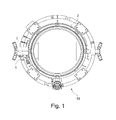
図1は、レーダー式の測定プローブ3の配置の一実施形態を示す平面図である。同図において、レーダー式の測定プローブ3は、水冷式のシールドハウジング1内に収納された状態で、ESR(エレクトロスラグ再溶解)装置10の同じく水冷式のモールド蓋(鋳型の蓋)2にフランジを介して取り付けられている。
FIG. 1 is a plan view showing an embodiment of an arrangement of radar
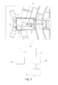
図2は、レーダー式の測定プローブ3を内部に有し、モールド蓋2にフランジを介して取り付けられたシールドハウジング1の一部切欠平面図を含む。同図において、シールドハウジング1は、モールドの内部空間の上方で曲げられて延在する測定用管体4、ガスをパージするためのパージ接続部5、およびレーダー式の測定プローブ3に給電したり測定信号を伝達したりするためのライン(配線)6を有する。同図に示すように、ライン6は、評価部15に接続されていてもよい。評価部15は、レーダー式の測定プローブ3によって得られた液面11(図3)のレベルを表示または表現するように構成されている。変形例として、またはこの構成に加えて、ライン6は、ESR装置10の制御部20に接続されていてもよい。制御部20は、スラグ浴9(図3)の液面11のレベルを一定に保持するか、またはスラグ浴9の液面11のレベルを一定時間ごとに所定の範囲内で選択的に変化させる。制御部20は、さらに、警告部21に接続されていてもよい。警告部21は、液面11のレベルが閾値を上回るか下回った際、または所定の変化速度および変化を超えて急激かつ顕著に変化した際に警告(アラーム)を発する。
FIG. 2 includes a partially cutaway plan view of a
図3は、シールドハウジング1およびその周辺の縦断面図である。同図からは、シールドハウジング1がレーダー式の測定プローブ3および曲げられた測定用管体4を有する様子と、測定用管体4が円錐状のホーンアンテナ7へと変化する様子とが見て取れる。同図からは、さらに、水冷式の上下スライド可能なモールド13の内壁8と、スラグ浴9の液面11(メタルライン)を見ることができる。また、同図には、レーダー式の測定プローブ3によって生成されるレーダービーム12が示されている。レーダービーム12は測定用管体4内で所定角度、例えば90°方向転換したうえで、好ましくは、液面11に対してほぼ垂直に当たる。レーダー式の測定プローブ3は公知の原理によって液面11のレベルを、好ましくは連続的に、検出する。
FIG. 3 is a longitudinal sectional view of the
図示の例示的な実施形態では、シールドハウジング1は、二重壁(二重シェル)構造のハウジングとして構成されており、二重壁の内部に冷却水を流すことにより、水冷可能である。また、シールドハウジング1の外表面または内表面(二重壁の内面も含む)には、任意で、電磁場を遮断するためのミューメタル層が設けられてもよい。ミューメタル層とは、比較的高い透磁率を有する軟質金属合金のことを指す。ミューメタル層は、特には、ニッケルを約75〜80%、鉄を約15%、ならびに銅、コバルトおよびモリブデンからなる群から選択された成分を約3〜4%含み得る。
In the illustrated exemplary embodiment, the
2 モールド蓋または保護ガスフード
3 レーダー式の測定プローブ
9 スラグ浴
10 エレクトロスラグ再溶解装置
11 スラグ浴の液面
12 測定プローブのレーダービーム
13 スライド可能なモールド
15 評価部
20 制御部
2 Mold lid or
Claims (10)
前記スラグ浴(9)の液面(11)のレベルが、レーダー式の測定プローブ(3)によって測定され、
前記レーダー式の測定プローブ(3)によって生成されたレーダービーム(12)が、前記スラグ浴(9)の液面(11)に当たるように案内され、
得られた液面(11)のレベルが評価部(15)を介して表示もしくは表現され、および/または得られた液面(11)のレベルを、前記スライド可能なモールド(13)からの鋳造体の引出しを制御する制御部(20)の入力信号として使用することにより、前記エレクトロスラグ再溶解装置(10)の運転中の前記スラグ浴(9)の液面(11)のレベルを一定に保持するか、もしくは一定時間ごとに所定の範囲内で選択的に変化させることを特徴とする、エレクトロスラグ再溶解方法。 Electroslag remelting method using a short slidable mold (13), wherein the level of the liquid level (11) of the slag bath (9) of the electroslag remelting device (10) is monitored. In the dissolution method,
The level of the liquid level (11) of the slag bath (9) is measured by a radar type measurement probe (3),
The radar beam (12) generated by the radar type measurement probe (3) is guided so as to hit the liquid surface (11) of the slag bath (9),
The level of the liquid level (11) obtained is displayed or expressed via the evaluation part (15) and / or the level of the liquid level (11) obtained is cast from the slidable mold (13). By using it as an input signal of the controller (20) that controls the withdrawal of the body, the level of the liquid level (11) of the slag bath (9) during operation of the electroslag remelting device (10) is kept constant An electroslag remelting method characterized by holding or selectively changing within a predetermined range at regular intervals.
前記スラグ浴(9)の液面(11)のレベルを検出するレーダー式の測定プローブ(3)が、前記モールド蓋(2)または保護ガスフードに設けられており、
前記測定プローブ(3)のレーダービーム(12)を前記スラグ浴(9)の液面(11)に当てることを特徴とする、エレクトロスラグ再溶解装置。 Electroslag remelting apparatus (10) for performing the electroslag remelting method according to any one of claims 1 to 5, wherein the mold lid (2) or protective gas for covering the slag bath (9) In an electroslag remelting device comprising a hood,
A radar type measurement probe (3) for detecting the level of the liquid surface (11) of the slag bath (9) is provided on the mold lid (2) or a protective gas hood,
Electroslag remelting device, wherein the radar beam (12) of the measuring probe (3) is applied to the liquid surface (11) of the slag bath (9).
Applications Claiming Priority (2)
| Application Number | Priority Date | Filing Date | Title |
|---|---|---|---|
| AT0080710A AT509736B1 (en) | 2010-05-14 | 2010-05-14 | METHOD AND DEVICE FOR CONTINUOUS RECORDING OF SLAG LEVEL IN ESU PLANTS WITH SHORT SLIDE COILS |
| ATA807/2010 | 2010-05-14 |
Publications (2)
| Publication Number | Publication Date |
|---|---|
| JP2011240407A true JP2011240407A (en) | 2011-12-01 |
| JP5690205B2 JP5690205B2 (en) | 2015-03-25 |
Family
ID=44583604
Family Applications (1)
| Application Number | Title | Priority Date | Filing Date |
|---|---|---|---|
| JP2011105826A Expired - Fee Related JP5690205B2 (en) | 2010-05-14 | 2011-05-11 | Apparatus and method for continuously detecting the level of slag in an electroslag remelting device with a short slidable mold |
Country Status (5)
| Country | Link |
|---|---|
| US (1) | US20110277950A1 (en) |
| EP (1) | EP2386366B1 (en) |
| JP (1) | JP5690205B2 (en) |
| CN (1) | CN102253383A (en) |
| AT (1) | AT509736B1 (en) |
Families Citing this family (6)
| Publication number | Priority date | Publication date | Assignee | Title |
|---|---|---|---|---|
| CN105511419B (en) * | 2014-09-25 | 2018-02-27 | 鞍钢股份有限公司 | Visual analysis method for temperature field of continuous casting crystallizer |
| CN105043504B (en) * | 2015-08-26 | 2018-06-19 | 上海船舶研究设计院 | A kind of side-mounted radar level telemetering equipment of liquid tank |
| AT517889B1 (en) * | 2015-10-28 | 2017-09-15 | Primetals Technologies Austria GmbH | Detecting a level of pouring in a mold |
| US10563286B2 (en) | 2016-05-25 | 2020-02-18 | Ald Vacuum Technologies Gmbh | Electroslag remelting process and melting vessel |
| CN107167622B (en) * | 2017-06-22 | 2023-08-08 | 中国工程物理研究院流体物理研究所 | Bent coaxial probe assembly |
| CN116479249A (en) * | 2023-04-25 | 2023-07-25 | 安徽富凯特材有限公司 | Electroslag remelting device and method for high-homogeneity stainless alloy steel |
Citations (9)
| Publication number | Priority date | Publication date | Assignee | Title |
|---|---|---|---|---|
| JPS57194772U (en) * | 1981-06-05 | 1982-12-10 | ||
| JPS6372839A (en) * | 1986-09-16 | 1988-04-02 | Daido Steel Co Ltd | Ingot drawing speed control method and control device in electroslag remelting |
| JPH05287400A (en) * | 1992-04-03 | 1993-11-02 | Daido Steel Co Ltd | Liquid slag level control method for electroslag melting equipment |
| JPH07224332A (en) * | 1994-02-15 | 1995-08-22 | Hitachi Metals Ltd | Method and device for shielding from atmosphere in electroslag remelting |
| JPH1029042A (en) * | 1996-04-11 | 1998-02-03 | Inteco Internatl Technische Beratung Gmbh | Chill mold and metal remelting method using the same |
| JPH10277706A (en) * | 1997-04-08 | 1998-10-20 | Mitsubishi Heavy Ind Ltd | Billet continuous caster and casting method |
| JP2002523753A (en) * | 1998-08-18 | 2002-07-30 | ユーエスエックス エンジニアーズ アンド コンサルタンツ,インコーポレーテツド | Measurement of material thickness |
| JP2004522852A (en) * | 2000-11-14 | 2004-07-29 | インテコ・インターナショナーレ・テクニシェ・ベラツング・ゲゼルシャフト・ミット・ベシュレンクテル・ハフツング | Method for producing metal ingot or billet by melting electrodes in conductive slag bath and apparatus for performing the same |
| JP2008178908A (en) * | 2006-11-15 | 2008-08-07 | Inteco Special Melting Technologies Gmbh | Metal electroslag remelting process and ingot mold used therefor |
Family Cites Families (13)
| Publication number | Priority date | Publication date | Assignee | Title |
|---|---|---|---|---|
| WO1980001572A1 (en) * | 1979-01-31 | 1980-08-07 | Inst Elektroswarki Patona | Method of automatic control of molten metal bath level in cristallizers |
| DE3003082A1 (en) * | 1979-05-16 | 1980-11-27 | Inst Elektroswarki Patona | METHOD FOR REGULATING THE RELATIVE SHIFTING OF CASTING BLOCK AND CHOCOLATE AND CHOCOLATE FOR CARRYING OUT THIS METHOD |
| JPH0616081B2 (en) * | 1988-10-06 | 1994-03-02 | 日本鋼管株式会社 | Distance measuring device |
| CA2036779A1 (en) * | 1990-02-26 | 1991-08-27 | Akio Nagamune | In-furnace level meter and antenna therefor |
| CA2038823A1 (en) * | 1990-03-30 | 1991-10-01 | Akio Nagamune | In-furnace slag level measuring method and apparatus therefor |
| CA2038825A1 (en) * | 1990-03-30 | 1991-10-01 | Akio Nagamune | In-furnace slag level measuring apparatus |
| US5298887A (en) * | 1991-10-04 | 1994-03-29 | Sentech Corporation | Molten metal gauging and control system employing a fixed position capacitance sensor and method therefor |
| NO178919C (en) * | 1994-03-18 | 1996-07-03 | Norsk Hydro As | Level control system for continuous or semi-continuous metal casting equipment |
| US5588324A (en) * | 1994-06-14 | 1996-12-31 | Speranza; Bernard E. | Method for determining the level of a submerged layer of liquified material |
| EP0995523A1 (en) * | 1998-10-23 | 2000-04-26 | Alusuisse Technology & Management AG | Vertical continuous casting plant with optimised molten metal level measuring |
| IL159634A0 (en) * | 2003-12-29 | 2004-06-01 | E E R Env Energy Resrc Israel | Transceiver unit, apparatus, system and method for detecting the level of waste in a furnace |
| EP1925681B1 (en) * | 2006-11-15 | 2011-04-27 | Inteco special melting technologies GmbH | Method for electro slag remelting of metals and mould therefor |
| EP2090387A1 (en) * | 2008-01-18 | 2009-08-19 | Corus Staal BV | Method and apparatus for monitoring the surfaces of slag and molten metal in a mould |
-
2010
- 2010-05-14 AT AT0080710A patent/AT509736B1/en not_active IP Right Cessation
-
2011
- 2011-03-04 EP EP11156928.1A patent/EP2386366B1/en not_active Not-in-force
- 2011-04-25 CN CN2011101029840A patent/CN102253383A/en active Pending
- 2011-05-11 JP JP2011105826A patent/JP5690205B2/en not_active Expired - Fee Related
- 2011-05-13 US US13/107,670 patent/US20110277950A1/en not_active Abandoned
Patent Citations (9)
| Publication number | Priority date | Publication date | Assignee | Title |
|---|---|---|---|---|
| JPS57194772U (en) * | 1981-06-05 | 1982-12-10 | ||
| JPS6372839A (en) * | 1986-09-16 | 1988-04-02 | Daido Steel Co Ltd | Ingot drawing speed control method and control device in electroslag remelting |
| JPH05287400A (en) * | 1992-04-03 | 1993-11-02 | Daido Steel Co Ltd | Liquid slag level control method for electroslag melting equipment |
| JPH07224332A (en) * | 1994-02-15 | 1995-08-22 | Hitachi Metals Ltd | Method and device for shielding from atmosphere in electroslag remelting |
| JPH1029042A (en) * | 1996-04-11 | 1998-02-03 | Inteco Internatl Technische Beratung Gmbh | Chill mold and metal remelting method using the same |
| JPH10277706A (en) * | 1997-04-08 | 1998-10-20 | Mitsubishi Heavy Ind Ltd | Billet continuous caster and casting method |
| JP2002523753A (en) * | 1998-08-18 | 2002-07-30 | ユーエスエックス エンジニアーズ アンド コンサルタンツ,インコーポレーテツド | Measurement of material thickness |
| JP2004522852A (en) * | 2000-11-14 | 2004-07-29 | インテコ・インターナショナーレ・テクニシェ・ベラツング・ゲゼルシャフト・ミット・ベシュレンクテル・ハフツング | Method for producing metal ingot or billet by melting electrodes in conductive slag bath and apparatus for performing the same |
| JP2008178908A (en) * | 2006-11-15 | 2008-08-07 | Inteco Special Melting Technologies Gmbh | Metal electroslag remelting process and ingot mold used therefor |
Non-Patent Citations (1)
| Title |
|---|
| JPN6014011829; 今井孝: '製銑・製鋼プロセスを対象としたマイクロ波レベル計の計測技術' R&D KOBE STEEL ENGINEERING REPORTS vol.57,No.3, 200712, P16-20, 株式会社神戸製鋼所 * |
Also Published As
| Publication number | Publication date |
|---|---|
| US20110277950A1 (en) | 2011-11-17 |
| EP2386366B1 (en) | 2016-08-24 |
| CN102253383A (en) | 2011-11-23 |
| AT509736A1 (en) | 2011-11-15 |
| AT509736B1 (en) | 2012-03-15 |
| JP5690205B2 (en) | 2015-03-25 |
| EP2386366A2 (en) | 2011-11-16 |
| EP2386366A3 (en) | 2012-10-10 |
Similar Documents
| Publication | Publication Date | Title |
|---|---|---|
| JP5690205B2 (en) | Apparatus and method for continuously detecting the level of slag in an electroslag remelting device with a short slidable mold | |
| US20150204837A1 (en) | Apparatus and Method for Predicting Slab Quality | |
| US3834445A (en) | Continuous casting mold having a breakout sensing and control device | |
| KR101839841B1 (en) | Apparatus and Method for measuring molten steel height | |
| KR101655750B1 (en) | Bleedout detection system | |
| JP5154997B2 (en) | Breakout prediction method in continuous casting. | |
| CN104936724A (en) | Process for continuous casting of ingots composed of titanium or titanium alloys | |
| KR100843937B1 (en) | Tundish molten steel continuous monitoring device | |
| CN116234648A (en) | Systems and methods for monitoring metal levels during casting | |
| CN110181034A (en) | Aluminum piston product qualification rate is improved with production line monitoring system | |
| JP6375765B2 (en) | Molten metal injection method | |
| KR102935931B1 (en) | Casting method and related device | |
| JP2019098394A (en) | Method and device for evaluating quality of steel | |
| JP2012148336A (en) | Cast slab defect prediction detection method, slab manufacturing method, slab defect occurrence prediction detection device, and continuous casting equipment provided with the slab defect occurrence prediction detection device | |
| JP4618555B2 (en) | Method and apparatus for controlling molten metal level in continuous casting | |
| JP3039254B2 (en) | Liquid surface position control device in continuous casting equipment | |
| US11951536B2 (en) | System and method for monitoring ingot detachment from bottom block | |
| JP5012161B2 (en) | Steel continuous casting method | |
| ES2980400T3 (en) | Casting method and casting apparatus for direct cooling casting | |
| JP4871023B2 (en) | Detection method of falling metal in injection pipe | |
| Vazquez | Tenova’s intelligent i BOF® technology, a modular package for BOF process improvement | |
| JP5472716B2 (en) | Method and apparatus for controlling molten metal level in continuous casting | |
| KR100775499B1 (en) | Refining furnace tap temperature measuring device | |
| Kashakashvili et al. | System for Automatically Regulating the Level of the Liquid Metal in Tundishes and Molds. | |
| JP2012055942A (en) | Apparatus for controlling bath level of continuous or semicontinuous molding device and method for controlling bath level |
Legal Events
| Date | Code | Title | Description |
|---|---|---|---|
| A621 | Written request for application examination |
Free format text: JAPANESE INTERMEDIATE CODE: A621 Effective date: 20130920 |
|
| A131 | Notification of reasons for refusal |
Free format text: JAPANESE INTERMEDIATE CODE: A131 Effective date: 20140902 |
|
| A521 | Written amendment |
Free format text: JAPANESE INTERMEDIATE CODE: A523 Effective date: 20141202 |
|
| TRDD | Decision of grant or rejection written | ||
| A01 | Written decision to grant a patent or to grant a registration (utility model) |
Free format text: JAPANESE INTERMEDIATE CODE: A01 Effective date: 20150106 |
|
| A61 | First payment of annual fees (during grant procedure) |
Free format text: JAPANESE INTERMEDIATE CODE: A61 Effective date: 20150130 |
|
| R150 | Certificate of patent or registration of utility model |
Ref document number: 5690205 Country of ref document: JP Free format text: JAPANESE INTERMEDIATE CODE: R150 |
|
| LAPS | Cancellation because of no payment of annual fees |