JP2011199234A - Device and method of mounting electronic component - Google Patents
Device and method of mounting electronic component Download PDFInfo
- Publication number
- JP2011199234A JP2011199234A JP2010134090A JP2010134090A JP2011199234A JP 2011199234 A JP2011199234 A JP 2011199234A JP 2010134090 A JP2010134090 A JP 2010134090A JP 2010134090 A JP2010134090 A JP 2010134090A JP 2011199234 A JP2011199234 A JP 2011199234A
- Authority
- JP
- Japan
- Prior art keywords
- electronic component
- tcp
- cleaning
- holding head
- adhesive tape
- Prior art date
- Legal status (The legal status is an assumption and is not a legal conclusion. Google has not performed a legal analysis and makes no representation as to the accuracy of the status listed.)
- Pending
Links
Images


Abstract
Description
この発明はたとえば基板としての液晶表示パネルに電子部品としてのTCP(Tape Carrier Package)を実装する電子部品の実装装置及び実装方法に関する。 The present invention relates to an electronic component mounting apparatus and mounting method for mounting a TCP (Tape Carrier Package) as an electronic component on a liquid crystal display panel as a substrate, for example.
基板としての液晶表示パネルを製造する場合、その液晶表示パネルに電子部品としてのTCPを実装装置によって実装するということが行われる。上記実装装置は箱型状の装置本体を有する。この装置本体内にはキヤリアテープから上記TCPを打ち抜く打ち抜き装置が設けられている。打ち抜き装置によって打ち抜かれたTCPは受け渡し手段を構成する受け体によって受け取られる。 When a liquid crystal display panel as a substrate is manufactured, TCP as an electronic component is mounted on the liquid crystal display panel by a mounting device. The mounting apparatus has a box-shaped apparatus main body. A punching device for punching out the TCP from the carrier tape is provided in the device main body. The TCP punched out by the punching device is received by the receiving body constituting the delivery means.
上記受け体は打ち抜かれたTCPを所定の位置まで搬送し、その位置で所定角度ずつ間欠的に回転駆動されるインデックステーブルに設けられた複数の保持ヘッドに受け渡されて吸着保持される。保持ヘッドは上下方向に駆動可能に設けられている。 The receiving body conveys the punched TCP to a predetermined position, and is delivered to and held by a plurality of holding heads provided on an index table that is rotationally driven intermittently at a predetermined angle at that position. The holding head is provided so as to be driven in the vertical direction.
インデックステーブルの保持ヘッドに受け渡されたTCPは、このインデックステーブルの間欠回転に応じて上記TCPの端子部を回転ブラシでクリーニングした後、実装位置に位置決めされる。その実装位置にはTCPが実装される基板がテーブル装置によって位置決めされて待機している。 The TCP delivered to the index table holding head is positioned at the mounting position after the TCP terminal portion is cleaned with a rotating brush in accordance with the intermittent rotation of the index table. At the mounting position, a substrate on which TCP is mounted is positioned by a table device and is on standby.
そして、インデックステーブルの間欠回転によってTCPを保持した上記保持ヘッドが実装位置に位置決めされると、その保持ヘッドは下方向に駆動される。それによって、保持ヘッドに保持された上記TCPが基板の側辺部に実装されるようになっている。このような先行技術は特許文献1や特許文献2に開示されている。
When the holding head holding the TCP is positioned at the mounting position by intermittent rotation of the index table, the holding head is driven downward. Thereby, the TCP held by the holding head is mounted on the side portion of the substrate. Such prior art is disclosed in Patent Document 1 and
従来は、基板の側辺部の全長にわたって異方性導電部材からなる粘着テープを貼着し、そこに上記TCPを所定間隔で実装するようにしていた。しかしながら、基板の側辺部の全長にわたって粘着テープを貼着したのでは、粘着テープのTCPが実装されない部分が無駄となったり、TCPが実装されていない部分に塵埃が付着するので好ましくないなどのことがある。 Conventionally, an adhesive tape made of an anisotropic conductive member is pasted over the entire length of the side portion of the substrate, and the TCP is mounted there at a predetermined interval. However, sticking the adhesive tape over the entire length of the side portion of the substrate is not preferable because the portion of the adhesive tape where the TCP is not mounted is wasted or dust adheres to the portion where the TCP is not mounted. Sometimes.
そこで、最近ではインデックステーブルの保持ヘッドに保持されたTCPの端子部を回転ブラシでクリーニングしたならば、インデックステーブルを所定角度回転させ、クリーニングされたTCPの端子部に貼着装置によってTCPの端子部とほぼ同じ長さに切断された粘着テープを貼着する。 Therefore, recently, if the TCP terminal part held by the index table holding head is cleaned with a rotating brush, the index table is rotated by a predetermined angle, and the TCP terminal part is attached to the cleaned TCP terminal part by a sticking device. Adhesive tape cut to approximately the same length as is attached.
そして、粘着テープが貼着されたTCPを上記保持ヘッドから実装ヘッドに受け渡し、この実装ヘッドを基板の側辺部の上方に位置決めしてから下降させることで、実装ヘッドに保持された上記TCPを基板の側辺部に実装するということが行われている。 Then, the TCP with the adhesive tape attached is transferred from the holding head to the mounting head, and the mounting head is positioned above the side portion of the substrate and then lowered, whereby the TCP held by the mounting head is lowered. Mounting on the side of the substrate is performed.
上記TCPを基板に実装する前に、その端子部を回転ブラシでクリーニングして塵埃を除去してから粘着テープを貼着すれば、その粘着テープをTCPの端子部に剥がれ難い状態で確実に貼着することが可能となる。 Before mounting the TCP on the board, clean the terminal part with a rotating brush to remove dust, and then apply the adhesive tape to the TCP terminal part. It becomes possible to wear.
ところで、TCPの端子部に粘着テープを貼着する前に、インデックステーブルの保持ヘッドに保持されたTCPの端子部を回転する回転ブラシを接触させてクリーニングすると、保持ヘッドに吸着保持されたTCPは回転ブラシとの接触抵抗によってずれ動くということがある。 By the way, before sticking the adhesive tape to the TCP terminal part, if the rotary terminal that rotates the TCP terminal part held by the holding head of the index table is contacted and cleaned, the TCP held by suction on the holding head becomes There is a case where it shifts due to contact resistance with the rotating brush.
保持ヘッドに保持されたTCPがずれ動くと、このTCPの端子部に所定の長さに切断された粘着テープを正規の位置に精密に貼着することができなくなるということがあり、その場合、TCPを実装ヘッドに受け渡して基板に実装しても、基板とTCPとの間に粘着テープが確実に介在しない状態の実装不良を招く虞がある。 If the TCP held by the holding head moves, the adhesive tape cut to a predetermined length on the terminal portion of the TCP may not be able to be precisely attached to a regular position. Even if the TCP is delivered to the mounting head and mounted on the substrate, there is a risk of mounting failure in a state where the adhesive tape is not reliably interposed between the substrate and the TCP.
しかも、粘着テープが貼着されて保持ヘッドに保持されたTCPが位置ずれしていると、実装ヘッドに円滑に受け渡すことができなくなったり、TCPの位置ずれ量が所定以上になると、上記TCPに設けられた位置合わせマークが位置決め用の撮像カメラの視野範囲から外れ、位置決めが行なえなくなるという虞もある。 In addition, if the TCP held on the holding head with the adhesive tape attached is misaligned, it cannot be smoothly delivered to the mounting head, or if the amount of TCP misalignment exceeds a predetermined value, the TCP There is also a possibility that the alignment mark provided in the position is out of the field of view of the imaging camera for positioning, and positioning cannot be performed.
この発明は、保持ヘッドに保持されて清掃された電子部品に粘着テープを貼着するとき、電子部品が保持ヘッドに位置ずれがない状態で保持されているようにすることで、電子部品の正規の位置に粘着テープを確実に貼着することができるようにした電子部品の実装装置及び実装方法を提供することにある。 In the present invention, when an adhesive tape is applied to an electronic component that has been cleaned by being held by a holding head, the electronic component is held in a state in which the holding head is not misaligned. It is an object of the present invention to provide an electronic component mounting apparatus and mounting method capable of reliably adhering an adhesive tape to the position.
この発明は、基板の側辺部に電子部品を実装する実装装置であって、
装置本体と、
この装置本体に設けられ上記電子部品を保持する複数の保持ヘッドを有するインデックス手段と、
このインデックス手段の上記保持ヘッドに保持された上記電子部品をクリーニング液によって清掃する清掃手段と、
上記保持ヘッドに保持された電子部品が上記清掃手段によって清掃される前と清掃された後のうちの少なくとも清掃された後に、上記電子部品を押圧して上記保持ヘッドに対して上記電子部品を位置決めする位置決め手段と
上記清掃手段によって清掃されて上記位置決め手段によって位置決めされた上記電子部品に粘着テープを貼着する貼着装置と、
この貼着装置で粘着テープが貼着された上記電子部品を上記基板に実装する実装手段と
を具備したことを特徴とする特徴とする電子部品の実装装置にある。
The present invention is a mounting device for mounting electronic components on the side of a substrate,
The device body;
Index means provided in the apparatus main body and having a plurality of holding heads for holding the electronic components;
Cleaning means for cleaning the electronic component held by the holding head of the index means with a cleaning liquid;
Before the electronic component held by the holding head is cleaned by the cleaning means and after being cleaned, the electronic component is pressed to position the electronic component with respect to the holding head. A positioning unit that performs cleaning, and an adhesive device that adheres an adhesive tape to the electronic component that is cleaned by the cleaning unit and positioned by the positioning unit;
An electronic component mounting apparatus comprising: mounting means for mounting the electronic component to which the adhesive tape is bonded by the bonding device on the substrate.
上記清掃手段は、
上下方向に駆動される上下可動体と、
上記クリーニング液が供給されるとともに、上記上下可動体によって上昇位置に駆動されたときに上記保持ヘッドに保持された上記電子部品に接触してこの電子部品を清掃する清掃部材と
によって構成されていることが好ましい。
The cleaning means includes
An up and down movable body driven in the up and down direction;
A cleaning member that supplies the cleaning liquid and cleans the electronic component by contacting the electronic component held by the holding head when driven to the raised position by the up-and-down movable body. It is preferable.
上記上下可動体には上記クリーニング液を収容した容器が設けられ、
上記清掃部材は回転ブラシであって、この回転ブラシは上記容器に収容された上記クリーニング液に径方向の下部を浸漬して回転駆動可能に設けられていて、
上記上下可動体が上昇位置に駆動されたときに、上記回転ブラシは回転駆動されなら上記容器から露出した径方向の上部が上記保持ヘッドに保持された上記電子部品の下面に接触する構成であることが好ましい。
The upper and lower movable body is provided with a container containing the cleaning liquid,
The cleaning member is a rotary brush, and the rotary brush is provided so as to be able to rotate by immersing the lower portion in the radial direction in the cleaning liquid housed in the container.
When the up-and-down movable body is driven to the raised position, if the rotary brush is driven to rotate, the radial upper portion exposed from the container contacts the lower surface of the electronic component held by the holding head. It is preferable.
上記位置決め手段は、上記上下可動体に水平方向に進退可能に設けられた押圧部材と、この押圧部材を水平方向に駆動して上記保持ヘッドに保持された上記電子部品の端面を押圧させる駆動手段を備え、
上記回転ブラシの回転方向は、上記押圧部材が上記電子部品に与える押圧力の方向と逆方向の接触力を上記電子部品に与えるよう設定されていることが好ましい。
The positioning means includes a pressing member provided on the vertically movable body so as to be movable back and forth in the horizontal direction, and a driving means for driving the pressing member in the horizontal direction to press the end surface of the electronic component held by the holding head. With
It is preferable that the rotation direction of the rotary brush is set so as to give the electronic component a contact force in a direction opposite to the direction of the pressing force that the pressing member applies to the electronic component.
上記容器には、この容器内のクリーニング液が減少したときに補給する補給タンクが接続されていることが好ましい。 It is preferable that a replenishment tank that replenishes when the cleaning liquid in the container is reduced is connected to the container.
上記清掃部材は、上記クリーニング液を吸収するテープ状の給液部材であって、この給液部材は供給リールから繰り出されて巻き取りリールに巻き取られることで走行するようになっていて、
上記給液部材の上記供給リールと上記巻き取りリールの間に位置する部分は、上記上下可動体が上昇方向に駆動されることで上記保持ヘッドに保持された上記電子部品に接触した状態で、上記電子部品に対して相対的に移動して上記電子部品を清掃する構成であることが好ましい。
The cleaning member is a tape-like liquid supply member that absorbs the cleaning liquid, and the liquid supply member is adapted to run by being unwound from a supply reel and wound on a take-up reel,
The portion of the liquid supply member located between the supply reel and the take-up reel is in a state in which the vertical movable body is driven in the upward direction and is in contact with the electronic component held by the holding head. It is preferable that the electronic component is cleaned by moving relative to the electronic component.
上記装置本体内には樹脂製のテープ状部材から上記電子部品を打ち抜く打ち抜き装置が設けられ、上記装置本体にはこの装置本体の上部から外部の気体を内部に導入し上記打ち抜き装置に沿って下方に流しその流れによって上記装置本体内の上記打ち抜き装置で生じた塵埃を底部から排出する塵埃除去手段が設けられていることが好ましい。 A punching device for punching out the electronic components from a resin tape-like member is provided in the device main body, and an external gas is introduced into the device main body from the upper part of the device main body and is lowered along the punching device. It is preferable that a dust removing means is provided for discharging the dust generated by the punching device in the apparatus main body from the bottom by the flow.
この発明は、基板の側辺部に電子部品を実装する実装方法であって、
複数の保持ヘッドを有するインデックス手段の上記保持ヘッドに上記電子部品を保持する工程と、
上記保持ヘッドに保持された上記電子部品をクリーニング液が供給される清掃手段によって清掃する工程と、
上記清掃手段によって清掃される前と清掃された後の少なくとも清掃された後で、上記保持ヘッドに保持された上記電子部品を押圧してこの電子部品を上記保持ヘッドに対して位置決めする工程と、
上記保持ヘッドに対して位置決めされた上記電子部品に粘着テープを貼着する工程と、
粘着テープが貼着された上記電子部品を上記基板に実装する工程と
を具備したことを特徴とする電子部品の実装方法にある。
The present invention is a mounting method for mounting an electronic component on a side portion of a substrate,
Holding the electronic component on the holding head of the index means having a plurality of holding heads;
Cleaning the electronic component held by the holding head with a cleaning means to which a cleaning liquid is supplied;
A step of pressing the electronic component held by the holding head and positioning the electronic component with respect to the holding head before being cleaned by the cleaning means and after being cleaned at least after being cleaned;
Attaching an adhesive tape to the electronic component positioned with respect to the holding head;
And mounting the electronic component having an adhesive tape attached to the substrate.
この発明によれば、インデックス手段の保持ヘッドに保持された電子部品を清掃したならば、粘着テープを貼着する前に、その電子部品を保持ヘッドに対して位置決めするようにしているから、上記電子部品に対して粘着テープを位置ずれなく正確に貼着することが可能となる。 According to the present invention, if the electronic component held by the holding head of the index means is cleaned, the electronic component is positioned with respect to the holding head before the adhesive tape is attached. It is possible to accurately stick the adhesive tape to the electronic component without displacement.
以下、この発明の実施の形態を図面を参照しながら説明する。
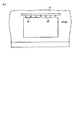
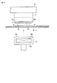
図1乃至図9はこの発明の第1の実施の形態を示す。図1は実装装置の内部構造を示す平面図、図2は同じく側面図である。図1と図2に示すように、上記実装装置はクリーンルームに設置される箱型状の装置本体1を備えている。この装置本体1の前後方向後端側の幅方向中央部には後方へ突出した突出部2が形成されていて、この突出部2にはテープ状部材としてのキヤリアテープ3から電子部品としてのTCP4を打ち抜くための第1の打ち抜き装置5Aと第2の打ち抜き装置5Bが装置本体1の幅方向の中心線O(図1に示す)に対して左右に対称に配置されている。
Embodiments of the present invention will be described below with reference to the drawings.
1 to 9 show a first embodiment of the present invention. FIG. 1 is a plan view showing the internal structure of the mounting apparatus, and FIG. 2 is a side view of the same. As shown in FIGS. 1 and 2, the mounting apparatus includes a box-shaped apparatus main body 1 installed in a clean room. A projecting
上記第1の打ち抜き装置5Aと第2の打ち抜き装置5Bは交互に稼動され、一方の打ち抜き装置5A又は5Bによって打ち抜かれたTCP4は一対の第1の受け渡し手段6A、6Bによって受け取られる。
The
すなわち、第1の打ち抜き装置5AによってTCP4を打ち抜いているときには第2の打ち抜き装置5Bが待機しており、第1の打ち抜き装置5Aに供給されるキヤリアテープ3からTCP4を打ち抜き終わったときに、第2の打ち抜き装置5Bが稼動されて第1の打ち抜き装置5Aにキヤリアテープ3の新たな部分が供給される。それによって、キヤリアテープ3から打ち抜かれたTCP4は一対の第1の受け渡し手段6A,6Bに交互に供給されるようになっている。
That is, when the
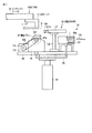
上記第1、第2の打抜き装置5A,5Bは、図2に示すように下面にポンチ11aが設けられた上金型11と、上記ポンチ11aが入り込む貫通孔12aが上下方向に形成された下金型12を備えている。上記上金型11は駆動源13によって矢印で示す上下方向に駆動されるようになっている。
As shown in FIG. 2, the first and
上記キヤリアテープ3は供給リール14から繰り出され、複数のガイドローラ15によって方向変換され、一部が上記下金型12の上面に沿って平行に走行するようガイドされて巻き取りリール16に巻き取られるようになっている。
The
なお、供給リール14にはキヤリアテープ3を保護する保護テープ17がキヤリアテープ3と重ねて巻装されている。上記供給リール14からキヤリアテープ3とともに繰り出された保護テープ17はキヤリアテープ3と分離され、上記打抜き装置5A,5BによってTCP4が打抜かれたキヤリアテープ3と一緒に上記巻き取りリール16に巻き取られるようになっている。
A
一方の上記第1の受け渡し手段6Aが受けたTCP4は第1のインデックス手段18Aまで搬送され、この第1のインデックス手段18Aに設けられた保持ヘッド19に受け取られる。
The
他方の第1の受け渡し手段6Bが受けたTCP4は第2のインデックス手段18Bまで搬送され、この第2のインデックス手段18Bに設けられた保持ヘッド19に受け取られる。
The
上記第1、第2のインデックス手段18A,18Bは、図2に示すように第1のθ駆動源21によって周方向に90度間隔で間欠的に回転駆動されるインデックステーブル22を有する。各インデックステーブル22の下面には周方向に90度間隔で複数の上記保持ヘッド19が設けられている。
As shown in FIG. 2, the first and second index means 18A and 18B have an index table 22 that is intermittently rotated at 90 ° intervals in the circumferential direction by a first
それによって、上記一対の第1の受け渡し手段6A,6Bによって搬送されたTCP4は各インデックス手段18A,18Bの保持ヘッド19によって吸着保持される。つまり、TCP4は第1の受け渡し手段6A,6Bからインデックス手段18A,18Bの保持ヘッド19に受け渡される。インデックス手段18A,18Bの保持ヘッド19がTCP4を受け取る受け取り位置を図1にAで示す。
なお、各インデックステーブル22の回転方向は図1に矢印で示すように逆方向となっている。
Thereby, the
The rotation direction of each index table 22 is reverse as shown by the arrow in FIG.
上記第1、第2の打ち抜き装置5A,5Bによって打ち抜かれたTCP4は、各受け渡し手段6A,6Bのそれぞれの受け具24によって交互に受け取られる。この受け具24は図2に矢印で示すX方向、つまり装置本体1の前後方向に沿って駆動されるXテーブル25にZθ駆動源23によって上下方向となるZ方向及び回転方向となるθ方向に駆動可能に設けられている。上記Xテーブル25は、X方向に沿って設けられたXガイド体26に移動可能に設けられ、図示しないリニアモータなどによって上記Xガイド体26に沿って駆動可能となっている。
The
一方の第1の受け渡し手段6Aの受け具24は、第1の打ち抜き装置5AからTCP4を受けると、図1に矢印Xで示す装置本体1の前後方向及び矢印Yで示す幅方向に駆動され、上記受け具24の上面に保持されたTCP4の一端部が第1のインデックス手段18Aのインデックステーブル22の下面に周方向に90度間隔で設けられた4つの保持ヘッド19のうちの、上記受け取り位置Aに位置決めされた保持ヘッド19の下方に対向するよう駆動位置決めされる。
When receiving the
同様に、他方の第1の受け渡し手段6Bの受け具24は、TCP4を受けると第2のインデックス手段18Bのインデックステーブル22の下面に周方向に90度間隔で設けられた4つの保持ヘッド19のうちの、上記受け取り位置Aに位置決めされた保持ヘッド19の下方に対向するよう駆動位置決めされる。
Similarly, the receiving tool 24 of the other first delivery means 6B receives the
位置決めされた受け具24はZθ駆動源23によって上昇方向に駆動される。それによって、受け具24に保持されたTCP4が上記インデックステーブル22に設けられた保持ヘッド19の下面に接触接近し、その状態でTCP4が上記受け具24から上記保持ヘッド19に受け渡されて吸着保持される。
The positioned receiver 24 is driven in the upward direction by the
TCP4が第1、第2のインデックス手段18A,18Bのインデックステーブル22に設けられた保持ヘッド19に受け渡されると、一対のインデックステーブル22は上記第1のθ駆動源21によって図1に矢印で示す逆方向にそれぞれ90度の角度で間欠的に回転駆動される。それによって、TCP4を吸着保持した各インデックステーブル22の保持ヘッド19は図1にBで示す清掃位置に位置決めされる。
When the
上記受け具24からTCP4を受けた保持ヘッド19がインデックステーブル22とともに周方向に90度回転駆動されて清掃位置Bに位置決めされると、上記保持ヘッド19に保持された上記TCP4の端子部(図示せず)は後述する清掃手段91によってクリーニングされる。それによって、端子部に付着した塵埃が除去される。
When the holding
上記保持ヘッド19に保持された上記TCP4は、上記清掃手段91によってクリーニングされる前と、クリーンニングされた後で、後述する位置決め手段92によって上記保持ヘッド19に対する保持位置が一定の位置になるよう位置決めされる。
The
TCP4の端子部が上記清掃手段91によってクリーニングされてから、上記位置決め手段92によって位置決めされると、そのTCP4を保持した保持ヘッド19は、インデックステーブル22とともに周方向に90度回転駆動されて図1にCで示す貼着位置に位置決めされる。
When the terminal portion of the
貼着位置Cに位置決めされたTCP4は、第1、第2の貼着装置31A,31Bによって上記TCP4のクリーニングされた端子部に、その端子部と対応する長さに切断された異方性導電部材からなら粘着テープ32が後述するように貼着される。
The
上記第1、第2のインデックス手段18A,18B及び第1、第2の貼着装置31A,31Bは、第1、第2の打ち抜き装置5A,5Bと同様、装置本体1の幅方向の中心線Oに対して左右対称に配置されている。
The first and second indexing means 18A and 18B and the first and
第1、第2のインデックス手段18A,18Bは第1、第2の打ち抜き装置5A,5Bよりも装置本体1の幅方向外方に配置され、第1、第2の貼着装置31A,31Bは第1、第2のインデックス手段18A,18Bよりも幅方向外方に配置されている。
The first and second indexing means 18A and 18B are arranged on the outer side in the width direction of the apparatus main body 1 relative to the first and
上記第1、第2の貼着装置31A,31Bは図2に示すように装置本体1内の底面に近い下部に配置された供給リール34を有する。この供給リール34には上記粘着テープ32が離型テープ35の一側面に貼着されて巻装されている。
The first and
離型テープ35の一側面に貼着された上記粘着テープ32は上記供給リール34から帯板状の支持ブロック33の板面に沿って上方にほぼ垂直に引き出され、第1のガイドローラ36によって粘着テープ32が上を向くよう水平方向に方向変換されて走行する。
The
図3に示すように、上記粘着テープ32が上記支持ブロック33に対向して垂直に走行する部分では、切断手段37を構成する駆動源37aによって二枚刃を有するカッタ37bが矢印で示す粘着テープ32に接近する方向に駆動されることで、その粘着テープ32に2本の切断線32aを所定間隔で形成する。なお、粘着テープ32が貼着された離型テープ35はカッタ37bによって切断されないよう、上記カッタ37bによる切込み量が設定されている。
As shown in FIG. 3, in a portion where the
上記粘着テープ32の2本の切断線32aによって他の部分と分離された部分、つまり抜き取り部分32bは切断手段37よりも上方に配置された抜き取り手段39によって抜き取られる。それによって、粘着テープ32は所定長さ、つまりTCP4に対応する長さに分離される。
The part separated from the other part by the two cutting
上記抜き取り手段39は、駆動源39aと、この駆動源39aによって上記粘着テープ32に接離する方向に駆動される押圧部39bと、この押圧部39bによって上記抜き取り部分32bに押圧される除去テープ40を有する。
The extraction means 39 includes a
除去テープ40の一部が上記押圧部39bによって粘着テープ32の抜き取り部分32bに押圧されることで、この抜き取り部分32bが除去テープ40に貼着されて除去される。なお、除去テープ40は図示しない供給リールから繰り出され、同じく図示しない巻き取りリールによって所定長さずつ巻き取られるようになっている。
When a part of the
所定長さに分断された粘着テープ32は、図2に示すように離型テープ35とともに上記第1のガイドローラ36によって水平方向に方向変換されて走行し、上記第1のガイドローラ36に対して所定間隔で配置された第2のガイドローラ41によって下方に方向変換される。
As shown in FIG. 2, the
上記離型テープ35の上記第1のガイドローラ36と第2のガイドローラ41との間の部分は、上記インデックステーブル22の貼着位置Cに位置決めされた保持ヘッド19に保持されたTCP4のクリーニングされた端子部の下面を走行する。
The portion of the
上記離型テープ35は、図示しない駆動源によって開閉駆動及び同図にZで示す上下方向に往復駆動されるチャック機構42によって挟持されて所定長さづつ間欠的に搬送される。つまり、離型テープ35の所定長さに切断された粘着テープ32が貼着された部分はチャック機構42によって貼着位置Cに位置決めされた保持ヘッド19の下方を水平に走行するようになっている。
The
上記離型テープ35がチャック機構42によって間欠的に搬送され、所定長さに分離された粘着テープ32が貼着位置Cに位置決めされた保持ヘッド19に保持されたTCP4の端子部の下方に対向するよう位置決めされると、その粘着テープ32は押し上げ手段43によって加熱されながら上記TCP4に加圧貼着される。
The
上記押し上げ手段43は、駆動源44によって上昇方向に駆動される加圧体45を有する。この加圧体45は熱源となるヒータ45aが内蔵されている。そして、加圧体45が上昇方向に駆動されると、この加圧体45は図10に示すようにクッションテープ47と離型テープ35を介して所定長さに分離された上記粘着テープ32を加熱しながら上記保持ヘッド19に保持された上記TCP4の端子部4aに加圧する。
The push-up means 43 has a
上記保持ヘッド19の下面と、上記加圧体45の上面との、所定長さに分離された上記粘着テープ32の両端部を押圧する部分は、他の部分に比べてわずかに高い強圧部19a,45bに形成されている。
A portion of the lower surface of the holding
上記強圧19a,45bの長さ寸法は、所定長さに分離された上記粘着テープ32の約4分の1程度或いはそれよりも短く設定され、高さは粘着テープ32の厚さの約半分で、たとえば10〜15μm程度に設定されている。
The lengths of the
それによって、図10に矢印で示すように加圧体45を上昇させて上記TCP4に所定長さに切断された上記粘着テープ32を加圧貼着する際、この粘着テープ32の両端部は上記強圧部19a,45bによって他の部分よりも強く加圧されることになる。
Thereby, when the pressure-
したがって、上記粘着テープ32をTCP4に貼着した後、この粘着テープ32から上記離型テープ35を剥離するときなどに、その粘着テープ32の両端部が離型テープ35によって引張られても、上記TCP4から剥離するのが防止される。つまり、離型テープ35の両端部にめくれが生じるのを防止することができる。
Therefore, even when both ends of the
なお、上記強圧部19a,45bは上記保持ヘッド19と上記加圧体45のどちらか一方だけに形成するようにしてもよい。
The
上記加圧体45の上面の全長は、上記強圧部45bが形成されているだけでなく、図11に示すように長手方向と交差する前後方向、つまり上記離型テープ35の幅方向に沿って凸状に湾曲した湾曲面45cに形成されている。この湾曲面45cの図11にhで示す高低差は上記粘着テープ32の厚さの半分或いはそれ以下であることが好ましい。
The total length of the upper surface of the
このように、上記加圧体45の上面を湾曲面45cに形成すれば、この加圧体45を矢印方向に上昇させ、その湾曲面45cによって上記粘着テープ32をTCP4の端子部に加圧するとき、上記粘着テープ32に作用する加圧力は、最初に幅方向の中心部に作用してから、幅方向の両端部へと移行することになる。
Thus, when the upper surface of the
そのため、上記TCP4の端子部4aに、図10に示すように端子部4aの長手方向に所定間隔で、しかも長手方向と交差する前後方向に沿って設けられた複数のリード線4b間の隙間に空気が残留し難くなるから、そのことによっても所定長さに切断された粘着テープ32がTCP4に対してめくれが生じ難い状態で確実に貼着されることになる。
Therefore, in the
上記粘着テープ32の貼着時、粘着テープ32はヒータ45aによって加熱されることで粘着性が向上するから、そのことによってもTCP4の端子部に確実に貼着されることになる。
When the
なお、上記保持ヘッド19と加圧体45に強圧部19a,45bを設けずに、加圧体45に湾曲面45cだけを設けるようにしてもよい。
The holding
このようにして、粘着テープ32がTCP4に貼着されると、図示しない離型ローラによってその粘着テープ32から離型テープ35が剥離される。剥離後、インデックステーブル22はさらに90度回転させられる。それによって、粘着テープ32が貼着されたTCP4を保持した保持ヘッド19は図1にDで示す受け渡し位置に位置決めされる。それと同時に、離型テープ35がチャック機構42によって搬送され、粘着テープ32の所定長さに切断された新たな部分が貼着位置CのTCP4に対向位置決めされる。なお、離型テープ35の粘着テープ32が貼着除去された部分は回収容器46に格納される。
In this way, when the
粘着テープ32が貼着されて受け渡し位置Dに位置決めされたTCP4は、一対の第2の受け渡し手段51A、51Bによってそれぞれ実装手段としての一対の実装ヘッド53にそれぞれ受け渡される。なお、一対の第2の受け渡し手段51A、51Bから一対の実装ヘッド53へのTCP4の受け渡しは、一対の第2の受け渡し手段51A、51Bの一方から一対の実装ヘッド53の一方に対して行った後、他方から他方の実装ヘッド53に対して行われる。つまり、TCP4は一対の実装ヘッド53に対して交互に受け渡されるようになっている。
The
図4に示すように、各第2の受け渡し手段51A、51BはX方向に沿って配置されたXガイド体55を有する。このXガイド体55には可動体56が図示せぬ駆動源によって駆動可能に設けられている。この可動体56にはZ駆動源57が設けられている。このZ駆動源57の駆動軸57aは上下方向であるZ方向に駆動されるようになっていて、その先端には側面形状がL字状の受け具54が取り付けられている。
As shown in FIG. 4, each of the second delivery means 51 </ b> A and 51 </ b> B has an
受け具54は、上記可動体56によってX方向に駆動され、その上面(吸着面)が上記受け渡し位置Dに位置決めされた保持ヘッド19に吸着保持されたTCP4の粘着テープ32が貼着されていない他端部に対向するよう位置決めされる。
The
ついで、受け具54は鎖線で示すようにZ方向上方に駆動されて上記TCP4の他端部の下面を吸着する。それと同時に、TCP4は保持ヘッド19による吸着保持が解除される。それによって、TCP4はインデックステーブル22の保持ヘッド19から受け具54に受け渡される。
Next, the
TCP4を受けた受け具54が下降すると、可動体56は図4に矢印Xで示す方向に駆動され、鎖線で示す位置に位置決めされる。それによって、受け具54は、その移動方向の上方で待機した上記実装ヘッド53の下方に対向するよう位置決めされる。実装ヘッド53はX・Y・Z・θ駆動源58によってX、Y、Z及びθ方向に駆動されるようになっている。
When the receiving
上記実装ヘッド53の下方に上記受け具54が位置決めされると、実装ヘッド53は下降方向に駆動されて受け具54に吸着保持されたTCP4の粘着テープ32が貼着された一端部の上面を吸着する。それと同時に、上記受け具54による上記TCP4の吸着状態が解除される。それによって、TCP4は上記受け具54から実装ヘッド53に受け渡される。
When the
TCP4を受けた実装ヘッド53は、図2に示すようにテーブル装置61の上面に吸着保持された基板Wの上記TCP4が実装される側部の上方に位置決めされる。実装ヘッド53と基板Wは図示しない撮像手段によって撮像され、その撮像手段からの撮像信号に基いて上記基板Wの実装位置の上方に上記TCP4が位置決めされるよう上記X・Y・Z・θ駆動源58によってX、Y及びθ方向に対して駆動される。
The mounting
上記実装ヘッド53に吸着保持されたTCP4が基板Wの実装位置の上方に位置決めされると、上記実装ヘッド53は上記X・Y・Z・θ駆動源58によって下降方向に駆動される。それによって、実装ヘッド53に吸着保持されたTCP4が基板Wの側辺部に実装される。
When the
このようにして、粘着テープ32が貼着された複数のTCP4が図1に鎖線で示すようにテーブル装置61の上面に吸着保持された基板Wの側辺部に対して所定間隔で順次実装される。
In this way, the plurality of
上記装置本体1内の前端部には一対のYガイドレール62が装置本体1の幅方向、つまりX方向と直交するY方向に沿って敷設されている。上記テーブル装置61は上記Yガイドレール62に移動可能に設けられていて、図示せぬ駆動源によってYガイドレール62に沿って駆動されるようになっている。
A pair of Y guide rails 62 are laid along the width direction of the apparatus main body 1, that is, in the Y direction orthogonal to the X direction, at the front end portion in the apparatus main body 1. The
図1に示すように、上記装置本体1の前端部の幅方向の一側部には供給口64が開口形成されている。上記テーブル装置61がYガイドレール62に沿って上記装置本体1の幅方向の一側部に移動したとき、図1に鎖線で示す供給装置63が上記供給口64から装置本体1内の上記テーブル装置61に基板Wを供給するようになっている。
As shown in FIG. 1, a
上記装置本体1の前端部の幅方向の他側部には排出口66が開口形成されている。上記テーブル装置61がYガイドレール62に沿って上記装置本体1の幅方向の他側部に移動したとき、図1に鎖線で示す排出装置65が上記排出口66から装置本体1内に入り込み、上記テーブル装置61の基板W、つまり側辺部に複数のTCP4が実装された基板Wを搬出するようになっている。
A
図5に示すように、上記装置本体1の両側部の上記供給口64と排出口66の上辺に対向する部位には、幅方向全長にわたって気体噴射手段としてのノズル体67が設けられている。ノズル体67には複数の噴射ノズル68が所定間隔で設けられ、これら噴射ノズル68から噴射される清浄な気体によって上記供給口64と排出口66にエアカーテンを形成する。それによって、装置本体1の外部から内部に塵埃を含む外気が入り込むのを防止している。
As shown in FIG. 5, a
図1に示すように、上記装置本体1の中央部は一対の打ち抜き装置5A,5B、一対のインデックス手段18A,18B及びテーブル装置61によって囲まれた空間部71が形成されている。この空間部71は図6に示すように装置本体1の上下方向全長にわたって貫通している。
As shown in FIG. 1, a central portion of the apparatus main body 1 is formed with a
上記空間部71に対向する上記装置本体1の天井部には送気ユニット72が設けられている。この送気ユニット72は図2に示すようにHEPAフィルタ73及び送気ファン74を内蔵したケーシング75を有し、HEPAフィルタ73によって清浄化されたクリーンルーム内の気体(空気)が送気ファン74によって上記ケーシング75の下端面に形成された吹出口76から装置本体1内に所定の流速で供給されるようになっている。
An
上記吹出口76は装置本体1の幅方向(Y方向)に沿って細長く形成されている。それによって、上記吹出口76から装置本体1内に供給される気体(図6に白抜きの矢印Mで示す)は装置本体1内に設けられた一対の打ち抜き装置5A,5B、つまり上下一対の金型11、12に沿って上方から下方に流れるようになっている。
The
上記空間部71に対向する上記装置本体1の底部には、上記送気ユニット72とで塵埃除去手段を構成する排気ユニット77が設けられている。この排気ユニット77は図2に示すようにケーシング78内に上記送気ユニット72から装置本体1の空間部71に供給された気体を吸引して排出する排気ファン79が設けられ、この排気ファン79によって吸引した装置本体1内の気体を下面の排気口80から外部に排出するようになっている。
At the bottom of the apparatus main body 1 facing the
上記送気ユニット72から供給された気体が上記空間部71内を所定の速度で流れて排気ユニット77から排出されると、その気体の流れによって装置本体1内には上記空間部71を流れる気体に向かう吸引力が発生する。吸引力によって発生する気流を図6に矢印Nで示す。
When the gas supplied from the
上記送気ユニット72から吐出されて排気ユニット77から排出される気流を主流とし、この主流の吸引力によって装置本体1内の上記主流に向かう雰囲気の流れを誘引流とする。
An air flow discharged from the
それによって、上記装置本体1内の上下一対の金型11、12でキヤリアテープ3からTCP4を打ち抜く際に発生する塵埃、上記一対のインデックステーブル22でTCP4から上記清掃手段91によって除去された塵埃、或いは装置本体1内の各種の駆動部分から発生する塵埃など、装置本体1内で種々の原因によって発生する塵埃は、上記空間部71を上下方向に流れる主流M及び主流Mの吸引力によって発生する誘引流Nによって排気ユニット77から外部に排出されることになる。すなわち、装置本体1内の中心部に塵埃が集まることで、塵埃が拡散して他の装置に付着するのを防止することができる。
Thereby, dust generated when the
図1に示すように、上記装置本体1の周壁のうち、たとえば幅方向の両側壁には開口部81が形成されている。各開口部81にはフィルタ82が設けられている。上記装置本体1の空間部71に気体が流れ、その気流Mによって吸引力が生じると、その吸引力によって装置本体1の外部の気体が上記フィルタ82で浄化された装置本体1内に導入されるようになっている。
As shown in FIG. 1,
装置本体1の側壁にフィルタ82を設けると、空間部71を流れる主流Mによって吸引力が発生することで、その吸引力によって装置本体1内には上記空間部71に向かう誘引流Nが発生し易くなる。つまり、主流Mの吸引力によって生じる誘引流Nの流量が増大する。それによって、装置本体1内で発生する塵埃が上記空間部71を流れる気流に巻き込まれ易くなる。
When the
つまり、装置本体1内に種々の原因によって塵埃が発生しても、その塵埃は装置本体1内を浮遊することなく、空間部71を流れる主流Mと誘引流Nによって外部に排出され易くなる。また、吸引力によってフィルタ82からは浄化された気体が導入される。
That is, even if dust is generated in the apparatus main body 1 due to various causes, the dust does not float in the apparatus main body 1 and is easily discharged to the outside by the main flow M and the induced flow N flowing through the
それによって、装置本体1内で発生した塵埃が、第1、第2の貼着装置31A,31Bの供給リール34から繰り出された粘着テープ32、第1、第2の貼着装置31A,31BからTCP4に貼着された粘着テープ32、或いはテーブル装置61に保持された基板Wの上面などに付着するのが防止される。しかも、浄化された気体で塵埃が流されて常に清浄な状態を維持することができる。
Thereby, dust generated in the apparatus main body 1 comes from the
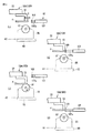
上記清掃手段91は図7に示すように平板状の上下可動体93を有する。この上下可動体93は駆動源としてのリニアモータ94によって、上記清掃位置Bの下方で上下方向に駆動されるようになっている。なお、リニアモータ94は上記上下可動体93を任意の高さ位置で位置決めできるようになっている。
As shown in FIG. 7, the cleaning means 91 has a plate-like vertical
上記上下可動体93の上面には透明な材料によって上面が開口形成された容器95が設けられている。この容器95の内部形状は図8に示すように断面が逆三角形状をなしていて、その内部には上記TCP4に付着した有機系の汚れなどを除去する溶剤などのクリーニング液Lが含浸された吸液体96が設けられている。
A
上記容器95の開口部分には清掃部材としての回転ブラシ97が設けられている。この回転ブラシ97は、軸線が水平になるよう、その支軸97aの両端部が上記容器95の側壁に設けられた軸受97bに回転可能に支持されている。
A rotating
上記回転ブラシ97は、図7に示すように上記各インデックス手段18A,18Bの保持ヘッド19に保持されたTCP4が上記清掃位置Bに位置決めされたとき、このTCP4の図示しないリードが設けられた一端部分の真下に位置し、しかも上記TCP4の幅方向に対して軸線が平行になるよう設置されている。
When the
図8に示すように、上記容器95に支持された回転ブラシ97の径方向の下方の部分は上記吸液体96に接触している。それによって、上記回転ブラシ97に上記容器95に収容された有機溶剤などのクリーニング液Lが供給されるようになっている。
As shown in FIG. 8, the lower portion in the radial direction of the rotating
上記容器95の最も低い位置には導液管98の一端が接続されている。この導液管98の他端は上面開口が蓋体95aによって閉塞された補給タンク99の底部に接続されている。この補給タンク99は内部にクリーニング液Lが収容され、その液面が上記容器95に設けられた吸液体96の上面よりも高い位置になるよう設置されている。
One end of a
それによって、上記容器95内のクリーニング液Lの液面が低下すると、上記補給タンク99内のクリーニング液Lが上記容器95に補給されるようになっている。上記補給タンク99内のクリーニング液Lの液面の下限はセンサ101によって検出される。
Thereby, when the liquid level of the cleaning liquid L in the
そして、センサ101が補給タンク99内のクリーニング液Lの液面の下限を検出すると、その検出信号でたとえば警報は出力されるなどして補給タンク99内のクリーニング液Lが所定以下に減少したことを作業者に知らせるようになっている。
When the
なお、上記補給タンク99は上記上下可動体93と別体に設けてもよいが、この実施の形態では上記上下可動体93の上面に上記容器95に対してクリーニング液Lを供給することができる高さで設けられている。
The
図7に示すように、上記上下可動体93の上面の、上記容器95よりもインデックス手段18A,18B側の部分には、回転駆動源102が設けられている。この回転駆動源102の出力軸に設けられた駆動プーリ103と、上記回転ブラシ97の一方の支軸97aに設けられた従動プーリ104との間にはベルト105が張設されている。したがって、上記回転駆動源102が作動すれば、上記回転ブラシ97は図7に矢印で示す時計方向に回転駆動されるようになっている。
As shown in FIG. 7, a
そして、上記上下可動体93を上記リニアモータ94によって上昇させ、上記回転ブラシ97を上記清掃位置Bに位置決めされた保持ヘッド19に保持されたTCP4のリードが設けられた部分の下面に接触させれば、このTCP4の下面は回転ブラシ97及びクリーニング液Lによって清掃されることになる。
Then, the vertical
上記上下可動体93の上面の、容器95を挟んで上記回転駆動源102と反対側の部分には上述した上記位置決め手段92を構成する駆動手段としてのシリンダ107が支持体108に支持されて設けられている。このシリンダ107は、その軸線を水平にし、しかも上記回転ブラシ97の径方向上端よりも上方に位置させている。
A
上記シリンダ107のロッド107aの先端には上記TCP4の幅寸法とほぼ同じ長さに形成された矩形板状の押圧部材109が取り付けられている。この押圧部材109は上記清掃位置Bに位置決めされたTCP4が上記回転ブラシ97によって清掃される前と、清掃された後で、上記TCP4を押圧して上記保持ヘッド19に対して位置決めするようになっている。
A rectangular plate-like pressing
すなわち、図9(a)に示すように、TCP4を上記回転ブラシ97によって清掃する前に、回転ブラシ97がTCP4に接触せずに、押圧部材109が保持ヘッド19に保持されたTCP4と対応する高さになるよう上記リニアモータ94によって上下可動体93を下降位置から第1の上昇位置H1まで上昇させる。
That is, as shown in FIG. 9A, before the
上下可動体93を第1の上昇位置まで上昇させたならば、図9(b)に示すようにシリンダ107を作動させて押圧部材109を前進させる。それによって、押圧部材109は保持ヘッド19に保持されたTCP4の端面を押圧するから、TCP4は端面が保持ヘッド19の端面に対して図9(a)にδで示すようにずれていても、これら両者の端面が一致するよう、TCP4が保持ヘッド19に対して位置決めされる。つまり、保持ヘッド19はTCP4を吸着保持しているから、押圧部材109によって押圧することでTCP4を保持ヘッド19に対して位置決めすることが可能である。
If the up-and-down
TCP4を清掃前に位置決めしたならば、図9(c)に示すように上記押圧部材109を後退させた後、上記上下可動体93を第1の上昇位置H1からさらに上昇させて、上記回転ブラシ97の径方向の上端側が保持ヘッド19に保持されたTCP4の下面に接触する高さ、つまり第2の高さ位置H2まで上昇させる。このとき、シリンダ107も回転ブラシ97と一緒に上昇する。
If the
上記回転ブラシ97は上下可動体93が第1の高さ位置H1から第2の高さ位置H2に上昇駆動されるときに、回転駆動源102によって図9(c)に矢印で示す時計方向に回転させられる。したがって、上下可動体93が第2の高さ位置に位置決めされることで、保持ヘッド19に保持されたTCP4の下面のリードが設けられた一端部分がクリーニング液Lを含む上記回転ブラシ97によって清掃されることになる。
The
つまり、TCP4を保持ヘッド19に対して位置決めしてから、このTCP4を回転ブラシ97で清掃するようにしている。そのため、保持ヘッド19に保持されたTCP4を、この保持ヘッド19に対して予め所定の位置になるよう設定された回転ブラシ97によって確実に清掃することが可能となる。
That is, after the
上記保持ヘッド19に保持されたTCP4には、上記回転ブラシ97の回転力によって上記押圧部材109によって押圧される方向と逆方向の摩擦力が作用する。そのため、TCP4は上記保持ヘッド19の下面で上記摩擦力の方向、つまり図9(a)に示すように位置ずれすることがある。
A frictional force in a direction opposite to the direction pressed by the pressing
そこで、回転ブラシ97による清掃が終了したならば、上下可動体93を第2の高さ位置H2から第1の高さ位置H1まで下降させて回転ブラシ97を停止させてから、図9(d)に示すように上記シリンダ107を作動させて上記押圧部材109を再度、前進方向に駆動する。
Therefore, when the cleaning with the rotating
それによって、保持ヘッド19の下面に保持されたTCP4は上記押圧部材109によって再度、上記保持ヘッド19に対して位置決めされる。つまり、回転ブラシ97でTCP4を清掃することで、TCP4が回転ブラシ97の摩擦力で位置ずれが生じても、その位置ずれが補正されることになる。
Thereby, the
回転ブラシ97の摩擦力によって上記保持ヘッド19に保持されたTCP4に生じる位置ずれの方向は、上記押圧部材109によって押圧される方向と逆方向である。そのため、回転ブラシ97による清掃でTCP4に位置ずれが生じても、その位置ずれは上記押圧部材109によってTCP4の端部を押圧することで、修正することができる。
The direction of displacement generated in the
したがって、TCP4を清掃位置Bで清掃した後、貼着位置Cで所定長さに分断された粘着テープ32を上記TCP4の下面に貼着する際、上記保持ヘッド19に位置ずれのない状態で保持された上記TCP4は上記貼着位置Cに精密に位置決めされることになるから、このTCP4に対して上記粘着テープ32を位置ずれが生じることなく確実に貼着することができる。
Therefore, after cleaning the
それによって、上記TCP4を基板Wに実装する際、TCP4に貼着された粘着テープ32の位置ずれによる実装不良を招くのを防止することができる。
Thereby, when the
一方、上記インデックステーブル22の清掃位置BでTCP4が清掃手段91の回転ブラシ97から供給されるクリーニング液Lによってクリーニングされると、TCP4の端子部には上記クリーニング液Lが付着残留する。そして、TCP4に付着したクリーニング液Lが確実に乾燥除去される前に、TCP4が貼着位置Cに搬送されて粘着テープ32が貼着されることがある。その場合、TCP4にクリーニング液Lが付着残留していることで、粘着テープ32の貼着不良を招く虞がある。
On the other hand, when the
しかしながら、上記清掃手段91が設けられた装置本体1内には、図6に矢印MとNで示すように空間部71から排気ユニット77に向かって気体が流れている。そのため、清掃位置BでクリーニングされたTCP4にクリーニング液Lが残留していても、そのクリーニング液Lは装置本体1内を流れる矢印MとNで示す気体によって乾燥が助長されることになる。
However, in the apparatus main body 1 provided with the cleaning means 91, gas flows from the
それによって、TCP4が清掃位置Bから貼着位置Cに搬送される間に、本体1内の気体の流れによってTCP4に付着残留したクリーニング液Lが乾燥されるため、貼着位置Cでの粘着テープ32の貼着を確実に行なうことができる。
As a result, while the
言い換えれば、TCP4に付着残留したクリーニング液が乾燥するまで、貼着位置Cで粘着テープ32の貼着を遅らせるということをせずに済むから、生産性を向上させることができる。
In other words, since it is not necessary to delay the sticking of the
上記清掃手段91で、保持ヘッド19に保持されたTCP4を押圧部材109によって位置決めする際、押圧部材109が保持ヘッド19の側面に圧接するまでTCP4の端面を上記押圧部材109で押圧して上記TCP4を位置決めするようにした。
When the
そのため、TCP4の一端部は保持ヘッド19の下端面(吸着面)から突出することなく保持されるから、その一端部に粘着テープ32を貼着する際、その一端部を撓ませることなく行なうことができる。それによって、TCP4の一端部に粘着テープ32を確実に貼着することができる。
Therefore, one end portion of the
しかも、押圧部材109を保持ヘッド19の側面に圧接させてTCP4を位置決めするため、保持ヘッド19に対するTCP4の位置決めを、上記押圧部材109によって正確に行なうことができるということもある。
Moreover, since the
上述した第1の実施の形態ではインデックステーブル22の清掃位置BでTCP4の端子部を清掃手段91によって清掃するようにしたが、清掃されることでTCP4に残留したクリーニング液Lの乾燥を考慮した場合、受け取り位置Aに清掃手段91を配置し、ここでTCP4の端子部をクリーニング液Lでクリーニングするようにしてもよい。
In the first embodiment described above, the terminal portion of the
このようにすれば、クリーニングされたTCP4が貼着位置Cに搬送されるまでの時間を長くしてクリーニング液Lの乾燥を助長することができるから、貼着位置CでのTCP4に対する粘着テープ32の貼着を、より一層、良好に行なうことが可能となる。
In this way, it is possible to lengthen the time until the cleaned
なお、TCP4のクリーニングの他の方法としては、打ち抜き装置5A,5Bによって打ち抜かれたTCP4が受け具24に受け渡された位置で、そのTCP4の端子部にクリーニング液Lを塗布する。
As another method for cleaning the
ついで、TCP4がインデックステーブル22の保持ヘッド19に受け渡されて清掃位置Bに搬送されたならば、ここでTCP4の端子部を乾燥状態或いはクリーニング液Lによってわずかに湿らされた状態にある布地などのクリーニング部材によってクリーニングする。
Then, if the
それによって、清掃位置Bで清掃されたTCP4にはクリーニング液Lがほとんど残留しない状態になるから、貼着位置Cでの粘着テープ32の貼着を良好に行なうことが可能となる。
Thereby, since the cleaning liquid L hardly remains in the
なお、上記受け具24はTCP4を単に上面で受けるだけであるから、この受け具24に受け渡されたTCP4にクリーニング液Lを塗布することができない。そこで、打ち抜き装置5A,5Bによって打ち抜かれたTCP4を、上記受け具24に代えて、図2に51A,51Bで示す第2の受け渡し手段によって、TCP4の一端部の下面を吸着保持する。それによって、一端部の下面が吸着保持されたTCP4の他端部の下面に、たとえばブラシなどの塗布手段によってクリーニング液Lを塗布することが可能となる。
In addition, since the said receiving tool 24 only receives TCP4 by an upper surface, the cleaning liquid L cannot be apply | coated to TCP4 delivered to this receiving tool 24. FIG. Therefore, the lower surface of one end portion of the
図12はこの発明の第2の実施の形態の清掃手段91Aを示す。この実施の形態の清掃手段91Aは、清掃位置Bに位置決めされた保持ヘッド19の下方にリニアモータ94によって上下方向に駆動される上下可動体93Aが設けられている。この上下可動体93Aの上面には清掃ローラ121が回転可能に設けられている。この清掃ローラ121は、保持ヘッド19に保持されたTCP4の幅寸法と同等或いはそれ以上の長さ寸法を備えている。
FIG. 12 shows a cleaning means 91A according to the second embodiment of the present invention. The cleaning means 91 </ b> A of this embodiment is provided with a vertically
この実施の形態では、上記リニアモータ94は上記上下可動体93A、つまり清掃ローラ121を図12に実線で示す下降位置と、鎖線で示す上昇位置との2段階で駆動するようになっている。
In this embodiment, the
上記清掃ローラ121にはテープ状の布ならなる給液部材122が係合している。この給液部材122は、供給リール123から上方に繰り出されてガイドパイプ124によって水平方向に方向変換された後、上記清掃ローラ121に係合している。
A
上記ガイドパイプ124には内部にクリーニング液Lが供給されるとともに、上記給液部材122と接触する部分に吸液孔124aが穿設されている。したがって、上記給液部材122には上記清掃ローラ121に到達する前に上記吸液孔124aから噴射されるクリーニング液Lが供給されるようになっている。
The
上記清掃ローラ121に係合した給液部材122はガイドローラ125によって水平方向から下方に向かって方向変換された後、巻き取りリール126に巻き取られるようになっている。
The
上記給液部材122の上記清掃ローラ121とガイドローラ125の間に位置する部分の上面には、図示しないガイドによって上下方向に移動可能にガイドされたテンションローラ127が係合している。このテンションローラ127にはワイヤ128の一端が連結されている。
A
上記ワイヤ128は上記テンションローラ127よりも下方に位置するウエイトローラ129に係合して上方向に導かれ、他端は固定部130に固定されている。上記ウエイトローラ129は図示せぬガイドによって上下方向に移動可能となっている。
The
したがって、上記給液部材122は、上記ウエイトローラ129の重量によってテンショが付与されるから、弛みが生じることなく走行するようになっている。
Accordingly, since the
上記給液部材122の走行方向は図10に矢印で示すように上記保持ヘッド19に保持されたTCP4の幅方向と交差する方向であって、しかも走行する給液部材122との接触抵抗によってTCP4に生じさせる力の方向が図10に矢印で示すようにTCP4を上記保持ヘッド19の先端方向へ移動させる方向に作用する。
The traveling direction of the
上記清掃位置Bに位置決めされた上記保持ヘッド19の先端側には、上記位置決め手段92が配置されている。つまり、位置決め手段92は軸線を水平にして配置されたシリンダ107、このシリンダ107のロッド107aの先端に設けられた押圧部材109からなる。
The positioning means 92 is disposed on the distal end side of the holding
上記構成によれば、保持ヘッド19に保持されたTCP4が清掃位置Bに位置決めされると、シリンダ107が作動して保持ヘッド19に保持された上記TCP4の先端面を押圧部材109によって押圧する。それによって、TCP4が保持ヘッド19に対して位置ずれしていれば、所定の位置に位置決めされることになる。
According to the above configuration, when the
TCP4が位置決めされたならば、リニアモータ94によって清掃ローラ121が同図に鎖線で示す上昇位置に駆動される。それによって、上記清掃ローラ121は給液部材122を図10に鎖線で示すように変形させながら上昇し、この給液部材122を上記TCP4の下面に圧接させる。
When the
ついで、巻き取りリール126が回転駆動されて給液部材122を矢印方向に走行させる。給液部材122にはクリーニング液Lが吸着されている。したがって、上記TCP4のリードが形成された下面の部分が清掃されることになる。
Next, the take-up
このようにしてTCP4が清掃されると、清掃ローラ121が下降位置に駆動される。それと同時に、シリンダ107が作動して保持ヘッド19に保持された上記TCP4の先端面を押圧部材109によって押圧する。つまり、TCP4は押圧部材109によって給液部材122から受けた摩擦力の方向と逆方向の押圧力を受ける。
When the
それによって、給液部材122を走行させてTCP4を清掃することで、TCP4が保持ヘッド19に対して位置ずれしても、上記押圧部材109によって上記保持ヘッド19に対して位置決めされることになるから、つぎの貼着位置Cで上記TCP4の下面に粘着テープ32を位置ずれが生じることなく確実に貼着することができる。
Accordingly, by cleaning the
なお、この第2の実施の形態において、クリーニング液Lを吸収した給液部材122を走行させてTCP4の下面を清掃するようにしたが、清掃手段91Aの清掃ローラ121、供給リール123、ガイドパイプ124、ガイドローラ125、巻き取りリール126及びウエイトローラ129などのTCP4を清掃する構成全体を図示せぬベース盤に設けるなどして一体化する。
In the second embodiment, the
そして、TCP4を清掃するとき、給液部材122を走行させずに、清掃手段91AをTCP4に対して移動させることで、このTCP4を清掃するようにしてもよい。
And when cleaning TCP4, you may make it clean this TCP4 by moving the cleaning means 91A with respect to TCP4, without making the
1…装置本体、3…キヤリアテープ、4…TCP(電子部品)、5A,5B…打ち抜き装置、6A,6B…第1の受け渡し手段、11…上金型、12…下金型、18A,18B…インデックス手段、19…保持ヘッド、22…インデックステーブル、31A,31B…貼着装置、32…粘着テープ、53…実装ヘッド(実装手段)、91,91A…清掃手段、92…位置決め手段、93…上下可動体、97…回転ブラシ、99…補給タンク、109…押圧部材、121…清掃ローラ、122…給液部材。 DESCRIPTION OF SYMBOLS 1 ... Apparatus body, 3 ... Carrier tape, 4 ... TCP (electronic component), 5A, 5B ... Punching device, 6A, 6B ... 1st delivery means, 11 ... Upper metal mold, 12 ... Lower metal mold, 18A, 18B ... index means, 19 ... holding head, 22 ... index table, 31A, 31B ... sticking device, 32 ... adhesive tape, 53 ... mounting head (mounting means), 91, 91A ... cleaning means, 92 ... positioning means, 93 ... Vertical movable body, 97: rotating brush, 99: replenishing tank, 109: pressing member, 121: cleaning roller, 122: liquid supply member.
Claims (10)
装置本体と、
この装置本体に設けられ上記電子部品を保持する複数の保持ヘッドを有するインデックス手段と、
このインデックス手段の上記保持ヘッドに保持された上記電子部品をクリーニング液によって清掃する清掃手段と、
上記保持ヘッドに保持された電子部品が上記清掃手段によって清掃される前と清掃された後のうちの少なくとも清掃された後に、上記電子部品を押圧して上記保持ヘッドに対して上記電子部品を位置決めする位置決め手段と
上記清掃手段によって清掃されて上記位置決め手段によって位置決めされた上記電子部品に粘着テープを貼着する貼着装置と、
この貼着装置で粘着テープが貼着された上記電子部品を上記基板に実装する実装手段と
を具備したことを特徴とする特徴とする電子部品の実装装置。 A mounting device for mounting electronic components on the side of a substrate,
The device body;
Index means provided in the apparatus main body and having a plurality of holding heads for holding the electronic components;
Cleaning means for cleaning the electronic component held by the holding head of the index means with a cleaning liquid;
Before the electronic component held by the holding head is cleaned by the cleaning means and after being cleaned, the electronic component is pressed to position the electronic component with respect to the holding head. A positioning unit that performs cleaning, and an adhesive device that adheres an adhesive tape to the electronic component that is cleaned by the cleaning unit and positioned by the positioning unit;
An electronic component mounting apparatus comprising: mounting means for mounting the electronic component to which the adhesive tape is bonded by the bonding apparatus on the substrate.
上下方向に駆動される上下可動体と、
上記クリーニング液が供給されるとともに、上記上下可動体によって上昇位置に駆動されたときに上記保持ヘッドに保持された上記電子部品に接触してこの電子部品を清掃する清掃部材と
によって構成されていることを特徴とする特徴とする請求項1記載の電子部品の実装装置。 The cleaning means includes
An up and down movable body driven in the up and down direction;
A cleaning member that supplies the cleaning liquid and cleans the electronic component by contacting the electronic component held by the holding head when driven to the raised position by the up-and-down movable body. The electronic component mounting apparatus according to claim 1, wherein:
上記清掃部材は回転ブラシであって、この回転ブラシは上記容器に収容された上記クリーニング液に径方向の下部を浸漬して回転駆動可能に設けられていて、
上記上下可動体が上昇位置に駆動されたときに、上記回転ブラシは回転駆動されなら上記容器から露出した径方向の上部が上記保持ヘッドに保持された上記電子部品の下面に接触する構成であることを特徴とする請求項2記載の電子部品の実装装置。 The upper and lower movable body is provided with a container containing the cleaning liquid,
The cleaning member is a rotary brush, and the rotary brush is provided so as to be able to rotate by immersing the lower portion in the radial direction in the cleaning liquid housed in the container.
When the up-and-down movable body is driven to the raised position, if the rotary brush is driven to rotate, the radial upper portion exposed from the container contacts the lower surface of the electronic component held by the holding head. The electronic component mounting apparatus according to claim 2, wherein:
上記回転ブラシの回転方向は、上記押圧部材が上記電子部品に与える押圧力の方向と逆方向の接触力を上記電子部品に与えるよう設定されていることを特徴とする請求項3記載の電子部品の実装装置。 The positioning means includes a pressing member provided on the vertically movable body so as to be movable back and forth in the horizontal direction, and a driving means for driving the pressing member in the horizontal direction to press the end surface of the electronic component held by the holding head. With
4. The electronic component according to claim 3, wherein the rotation direction of the rotary brush is set so as to apply a contact force to the electronic component in a direction opposite to the direction of the pressing force applied to the electronic component by the pressing member. Mounting equipment.
上記給液部材の上記供給リールと上記巻き取りリールの間に位置する部分は、上記上下可動体が上昇方向に駆動されることで上記保持ヘッドに保持された上記電子部品に接触した状態で、上記電子部品に対して相対的に移動して上記電子部品を清掃する構成であることを特徴とする請求項2記載の電子部品の実装装置。 The cleaning member is a tape-like liquid supply member that absorbs the cleaning liquid, and the liquid supply member is adapted to run by being unwound from a supply reel and wound on a take-up reel,
The portion of the liquid supply member located between the supply reel and the take-up reel is in a state in which the vertical movable body is driven in the upward direction and is in contact with the electronic component held by the holding head. 3. The electronic component mounting apparatus according to claim 2, wherein the electronic component is cleaned by moving relative to the electronic component.
上記保持ヘッドと上記加圧体との上記粘着テープを加圧する面の少なくともどちらか一方には、上記粘着テープの両端部を他の部分よりも強く加圧する強圧部が形成されていることを特徴とする請求項1記載の電子部品の実装装置。 The sticking apparatus has a pressure body that presses and sticks the adhesive tape to the terminal part of the electronic component held by the holding head,
At least one of the surfaces of the holding head and the pressure member that presses the adhesive tape is formed with a strong pressure portion that presses both ends of the adhesive tape more strongly than the other portions. The electronic component mounting apparatus according to claim 1.
上記加圧体の上面は、上記粘着テープの幅方向に沿って凸状に湾曲した湾曲面に形成されていることを特徴とする請求項1記載の電子部品の実装装置。 The sticking apparatus has a pressure body that presses and sticks the adhesive tape to the terminal part of the electronic component held by the holding head,
2. The electronic component mounting apparatus according to claim 1, wherein an upper surface of the pressurizing body is formed on a curved surface that is curved in a convex shape along the width direction of the adhesive tape.
複数の保持ヘッドを有するインデックス手段の上記保持ヘッドに上記電子部品を保持する工程と、
上記保持ヘッドに保持された上記電子部品をクリーニング液が供給される清掃手段によって清掃する工程と、
上記清掃手段によって清掃される前と清掃された後の少なくとも清掃された後で、上記保持ヘッドに保持された上記電子部品を押圧してこの電子部品を上記保持ヘッドに対して位置決めする工程と、
上記保持ヘッドに対して位置決めされた上記電子部品に粘着テープを貼着する工程と、
粘着テープが貼着された上記電子部品を上記基板に実装する工程と
を具備したことを特徴とする電子部品の実装方法。 A mounting method for mounting an electronic component on a side of a substrate,
Holding the electronic component on the holding head of the index means having a plurality of holding heads;
Cleaning the electronic component held by the holding head with a cleaning means to which a cleaning liquid is supplied;
A step of pressing the electronic component held by the holding head and positioning the electronic component with respect to the holding head before being cleaned by the cleaning means and after being cleaned at least after being cleaned;
Attaching an adhesive tape to the electronic component positioned with respect to the holding head;
Mounting the electronic component to which the adhesive tape has been attached to the substrate.
Priority Applications (1)
| Application Number | Priority Date | Filing Date | Title |
|---|---|---|---|
| JP2010134090A JP2011199234A (en) | 2010-02-26 | 2010-06-11 | Device and method of mounting electronic component |
Applications Claiming Priority (3)
| Application Number | Priority Date | Filing Date | Title |
|---|---|---|---|
| JP2010042513 | 2010-02-26 | ||
| JP2010042513 | 2010-02-26 | ||
| JP2010134090A JP2011199234A (en) | 2010-02-26 | 2010-06-11 | Device and method of mounting electronic component |
Publications (2)
| Publication Number | Publication Date |
|---|---|
| JP2011199234A true JP2011199234A (en) | 2011-10-06 |
| JP2011199234A5 JP2011199234A5 (en) | 2013-07-25 |
Family
ID=44877020
Family Applications (1)
| Application Number | Title | Priority Date | Filing Date |
|---|---|---|---|
| JP2010134090A Pending JP2011199234A (en) | 2010-02-26 | 2010-06-11 | Device and method of mounting electronic component |
Country Status (1)
| Country | Link |
|---|---|
| JP (1) | JP2011199234A (en) |
Citations (4)
| Publication number | Priority date | Publication date | Assignee | Title |
|---|---|---|---|---|
| JPH09153526A (en) * | 1995-09-27 | 1997-06-10 | Toshiba Corp | Carrier device and method of tcp as well as manufacturing method of plane displayer |
| JP2006120929A (en) * | 2004-10-22 | 2006-05-11 | Shibaura Mechatronics Corp | Mounting apparatus and method for mounting electronic component |
| JP2009026831A (en) * | 2007-07-17 | 2009-02-05 | Shibaura Mechatronics Corp | Mounting device for electronic component |
| JP2010272754A (en) * | 2009-05-22 | 2010-12-02 | Panasonic Corp | Component-mounting device and method therefor |
-
2010
- 2010-06-11 JP JP2010134090A patent/JP2011199234A/en active Pending
Patent Citations (4)
| Publication number | Priority date | Publication date | Assignee | Title |
|---|---|---|---|---|
| JPH09153526A (en) * | 1995-09-27 | 1997-06-10 | Toshiba Corp | Carrier device and method of tcp as well as manufacturing method of plane displayer |
| JP2006120929A (en) * | 2004-10-22 | 2006-05-11 | Shibaura Mechatronics Corp | Mounting apparatus and method for mounting electronic component |
| JP2009026831A (en) * | 2007-07-17 | 2009-02-05 | Shibaura Mechatronics Corp | Mounting device for electronic component |
| JP2010272754A (en) * | 2009-05-22 | 2010-12-02 | Panasonic Corp | Component-mounting device and method therefor |
Similar Documents
| Publication | Publication Date | Title |
|---|---|---|
| JP5173708B2 (en) | Electronic component mounting apparatus and mounting method | |
| TWI449094B (en) | Cutter blade cleaning method and cutter blade cleaning device, as well as adhesive tape joining apparatus including the same | |
| JP5406980B2 (en) | Plastic film peeling device | |
| JP5173709B2 (en) | Electronic component mounting apparatus and mounting method | |
| KR101466343B1 (en) | Automatic banding appratus and attery Cell side tape Automatic Adhesion Machine the same | |
| WO1998012908A1 (en) | Method and apparatus for packaging ic chip, and tape-shaped carrier to be used therefor | |
| JP5702110B2 (en) | Electronic component mounting apparatus and mounting method | |
| JP5317615B2 (en) | Electronic component mounting apparatus and mounting method | |
| CN101080283B (en) | Substrate cleaning device and cleaning method | |
| JP2012019189A (en) | Apparatus and method for mounting electronic component | |
| TWI704632B (en) | Sheet peeling device and peeling method | |
| JP2011199234A (en) | Device and method of mounting electronic component | |
| JP4417824B2 (en) | Film sticking apparatus and film sticking method | |
| JP4770608B2 (en) | Film peeling device | |
| JP5650983B2 (en) | Electronic component mounting apparatus and mounting method | |
| JP2012193021A (en) | Adhering device and adhering method of adhesive tape | |
| JP5465043B2 (en) | Adhesive tape sticking device and sticking method | |
| JP5336153B2 (en) | Electronic component mounting apparatus and mounting method | |
| JP2004291997A (en) | Seal tape forming-pasting device, and seal tape forming-pasting method | |
| JPH06268022A (en) | Device for attaching conductive film | |
| JP2009164322A (en) | Device and method for applying adhesive tape | |
| JP2702023B2 (en) | Web adhesive tape feeder | |
| JP2788142B2 (en) | Bonded web cutting equipment | |
| JP2788145B2 (en) | Web connection device | |
| JP4697780B2 (en) | Tape peeling device |
Legal Events
| Date | Code | Title | Description |
|---|---|---|---|
| A521 | Written amendment |
Free format text: JAPANESE INTERMEDIATE CODE: A523 Effective date: 20130611 |
|
| A621 | Written request for application examination |
Free format text: JAPANESE INTERMEDIATE CODE: A621 Effective date: 20130611 |
|
| A977 | Report on retrieval |
Free format text: JAPANESE INTERMEDIATE CODE: A971007 Effective date: 20140116 |
|
| A131 | Notification of reasons for refusal |
Free format text: JAPANESE INTERMEDIATE CODE: A131 Effective date: 20140121 |
|
| A02 | Decision of refusal |
Free format text: JAPANESE INTERMEDIATE CODE: A02 Effective date: 20140603 |