JP2011198575A - Heating element cooling device - Google Patents
Heating element cooling device Download PDFInfo
- Publication number
- JP2011198575A JP2011198575A JP2010062979A JP2010062979A JP2011198575A JP 2011198575 A JP2011198575 A JP 2011198575A JP 2010062979 A JP2010062979 A JP 2010062979A JP 2010062979 A JP2010062979 A JP 2010062979A JP 2011198575 A JP2011198575 A JP 2011198575A
- Authority
- JP
- Japan
- Prior art keywords
- heating element
- cooling device
- wall surface
- battery
- intake duct
- Prior art date
- Legal status (The legal status is an assumption and is not a legal conclusion. Google has not performed a legal analysis and makes no representation as to the accuracy of the status listed.)
- Granted
Links
Images


Classifications
-
- B—PERFORMING OPERATIONS; TRANSPORTING
- B60—VEHICLES IN GENERAL
- B60H—ARRANGEMENTS OF HEATING, COOLING, VENTILATING OR OTHER AIR-TREATING DEVICES SPECIALLY ADAPTED FOR PASSENGER OR GOODS SPACES OF VEHICLES
- B60H1/00—Heating, cooling or ventilating [HVAC] devices
- B60H1/00271—HVAC devices specially adapted for particular vehicle parts or components and being connected to the vehicle HVAC unit
- B60H1/00278—HVAC devices specially adapted for particular vehicle parts or components and being connected to the vehicle HVAC unit for the battery
-
- B—PERFORMING OPERATIONS; TRANSPORTING
- B60—VEHICLES IN GENERAL
- B60L—PROPULSION OF ELECTRICALLY-PROPELLED VEHICLES; SUPPLYING ELECTRIC POWER FOR AUXILIARY EQUIPMENT OF ELECTRICALLY-PROPELLED VEHICLES; ELECTRODYNAMIC BRAKE SYSTEMS FOR VEHICLES IN GENERAL; MAGNETIC SUSPENSION OR LEVITATION FOR VEHICLES; MONITORING OPERATING VARIABLES OF ELECTRICALLY-PROPELLED VEHICLES; ELECTRIC SAFETY DEVICES FOR ELECTRICALLY-PROPELLED VEHICLES
- B60L58/00—Methods or circuit arrangements for monitoring or controlling batteries or fuel cells, specially adapted for electric vehicles
- B60L58/10—Methods or circuit arrangements for monitoring or controlling batteries or fuel cells, specially adapted for electric vehicles for monitoring or controlling batteries
- B60L58/24—Methods or circuit arrangements for monitoring or controlling batteries or fuel cells, specially adapted for electric vehicles for monitoring or controlling batteries for controlling the temperature of batteries
- B60L58/26—Methods or circuit arrangements for monitoring or controlling batteries or fuel cells, specially adapted for electric vehicles for monitoring or controlling batteries for controlling the temperature of batteries by cooling
-
- H—ELECTRICITY
- H01—ELECTRIC ELEMENTS
- H01M—PROCESSES OR MEANS, e.g. BATTERIES, FOR THE DIRECT CONVERSION OF CHEMICAL ENERGY INTO ELECTRICAL ENERGY
- H01M10/00—Secondary cells; Manufacture thereof
- H01M10/60—Heating or cooling; Temperature control
- H01M10/61—Types of temperature control
- H01M10/613—Cooling or keeping cold
-
- H—ELECTRICITY
- H01—ELECTRIC ELEMENTS
- H01M—PROCESSES OR MEANS, e.g. BATTERIES, FOR THE DIRECT CONVERSION OF CHEMICAL ENERGY INTO ELECTRICAL ENERGY
- H01M10/00—Secondary cells; Manufacture thereof
- H01M10/60—Heating or cooling; Temperature control
- H01M10/62—Heating or cooling; Temperature control specially adapted for specific applications
- H01M10/625—Vehicles
-
- H—ELECTRICITY
- H01—ELECTRIC ELEMENTS
- H01M—PROCESSES OR MEANS, e.g. BATTERIES, FOR THE DIRECT CONVERSION OF CHEMICAL ENERGY INTO ELECTRICAL ENERGY
- H01M10/00—Secondary cells; Manufacture thereof
- H01M10/60—Heating or cooling; Temperature control
- H01M10/65—Means for temperature control structurally associated with the cells
- H01M10/656—Means for temperature control structurally associated with the cells characterised by the type of heat-exchange fluid
- H01M10/6561—Gases
- H01M10/6566—Means within the gas flow to guide the flow around one or more cells, e.g. manifolds, baffles or other barriers
-
- B—PERFORMING OPERATIONS; TRANSPORTING
- B60—VEHICLES IN GENERAL
- B60H—ARRANGEMENTS OF HEATING, COOLING, VENTILATING OR OTHER AIR-TREATING DEVICES SPECIALLY ADAPTED FOR PASSENGER OR GOODS SPACES OF VEHICLES
- B60H1/00—Heating, cooling or ventilating [HVAC] devices
- B60H1/00271—HVAC devices specially adapted for particular vehicle parts or components and being connected to the vehicle HVAC unit
- B60H2001/003—Component temperature regulation using an air flow
-
- Y—GENERAL TAGGING OF NEW TECHNOLOGICAL DEVELOPMENTS; GENERAL TAGGING OF CROSS-SECTIONAL TECHNOLOGIES SPANNING OVER SEVERAL SECTIONS OF THE IPC; TECHNICAL SUBJECTS COVERED BY FORMER USPC CROSS-REFERENCE ART COLLECTIONS [XRACs] AND DIGESTS
- Y02—TECHNOLOGIES OR APPLICATIONS FOR MITIGATION OR ADAPTATION AGAINST CLIMATE CHANGE
- Y02E—REDUCTION OF GREENHOUSE GAS [GHG] EMISSIONS, RELATED TO ENERGY GENERATION, TRANSMISSION OR DISTRIBUTION
- Y02E60/00—Enabling technologies; Technologies with a potential or indirect contribution to GHG emissions mitigation
- Y02E60/10—Energy storage using batteries
-
- Y—GENERAL TAGGING OF NEW TECHNOLOGICAL DEVELOPMENTS; GENERAL TAGGING OF CROSS-SECTIONAL TECHNOLOGIES SPANNING OVER SEVERAL SECTIONS OF THE IPC; TECHNICAL SUBJECTS COVERED BY FORMER USPC CROSS-REFERENCE ART COLLECTIONS [XRACs] AND DIGESTS
- Y02—TECHNOLOGIES OR APPLICATIONS FOR MITIGATION OR ADAPTATION AGAINST CLIMATE CHANGE
- Y02T—CLIMATE CHANGE MITIGATION TECHNOLOGIES RELATED TO TRANSPORTATION
- Y02T10/00—Road transport of goods or passengers
- Y02T10/60—Other road transportation technologies with climate change mitigation effect
- Y02T10/70—Energy storage systems for electromobility, e.g. batteries
Abstract
Description
本発明は、発熱体冷却装置に関する。 The present invention relates to a heating element cooling device.
特許文献1には、吸気管の途中に水溜部を設けた発熱体冷却装置が開示されている。 Patent Document 1 discloses a heating element cooling device in which a water reservoir is provided in the middle of an intake pipe.
上記従来の発熱体冷却装置において、発熱体への液体の浸入をより抑制して欲しいとのニーズがある。
本発明の目的は、発熱体への液体の浸入を抑制できる発熱体冷却装置を提供することにある。
In the above-described conventional heating element cooling device, there is a need to further suppress the penetration of liquid into the heating element.
The objective of this invention is providing the heat generating body cooling device which can suppress the penetration | invasion of the liquid to a heat generating body.
上記目的を達成するために、本発明では、発熱体収容空間に車室内空気を取り入れる吸気管に、発熱体収容空間を画成する一壁面と隣接する膨出部を設け、この膨出部に、前記壁面と対面する排水孔を形成した。 In order to achieve the above object, according to the present invention, a bulging portion adjacent to one wall surface defining the heating element housing space is provided in the intake pipe for taking the air in the vehicle interior into the heating element housing space. A drainage hole facing the wall surface was formed.
よって、本発明にあっては、吸気管に浸入した液体を排水孔から吸気管外へ流出させた後、壁面を伝わせて下方へ排出できるため、発熱体への液体の浸入を抑制できる。 Therefore, in the present invention, after the liquid that has entered the intake pipe flows out of the intake pipe from the drain hole, the liquid can be discharged downward along the wall surface, so that the liquid can be prevented from entering the heating element.
以下、本発明の発熱体冷却装置を実現するための実施の形態を、図面に基づく実施例1を用いて説明する。 Hereinafter, an embodiment for realizing a heating element cooling device of the present invention is described using Example 1 based on a drawing.
〔実施例1〕
まず、構成を説明する。
(全体構造)
図1は実施例1のバッテリ冷却装置の背面図、図2は実施例1のバッテリ冷却装置の左側面図である。
実施例1のバッテリ冷却装置(発熱体冷却装置)1は、ハイブリッド車両または電動車両の駆動用モータに電力を供給する強電バッテリ(以下、単にバッテリと記す。)2を冷却する装置である。実施例1において、バッテリ2は、車室内6に設置された後部座席3の車両後方側であって、車室内6とトランクルーム(荷室)4との間に設定されたバッテリ収容空間(発熱体収容空間)5に設置される。バッテリ2は、図に示す矩形の筐体に発熱体として図外のバッテリモジュールが収容された構造である。
[Example 1]
First, the configuration will be described.
(Overall structure)
FIG. 1 is a rear view of the battery cooling device of the first embodiment, and FIG. 2 is a left side view of the battery cooling device of the first embodiment.
A battery cooling device (heating element cooling device) 1 according to the first embodiment is a device that cools a high-power battery (hereinafter simply referred to as a battery) 2 that supplies electric power to a drive motor of a hybrid vehicle or an electric vehicle. In the first embodiment, the
バッテリ収容空間5と車室内6は、室内トリム7および室内パネル8によって仕切られている。また、バッテリ収容空間5とトランクルーム4は、フロントトランクトリム9によって仕切られている。バッテリ収容空間5およびトランクルーム4の車幅方向左右には、車体パネル27a,27bとの間にサイドトランクトリム28a,28bが立設している。
トランクルーム4は、床板10によって上部空間4aと下部空間4bとに仕切られている。上部空間4aは、乗員が荷物を置くスペースとして利用する荷室として用いられる。下部空間4bは、スペアタイヤ11の収納空間として用いられる。フロントトランクトリム9の下方は、トランクルーム4の下部空間4bの上方に位置する。このため、バッテリ収容空間5と下部空間4bは、フロントトランクトリム9の下方で連通している。
The
The
実施例1のバッテリ冷却装置1は、吸気口12と、第1吸気ダクト(吸気管)13と、ブロワ14と、第2吸気ダクト15と、排気ダクト16と、排気口17とを備える。
吸気口12は、車室内空気の取り入れ口であり、室内トリム7の上部に固定されている。
第1吸気ダクト13は、車室内6からバッテリ2へと車室内空気を取り入れるためのもので、バッテリ2の上方に配置され、車幅方向に延在している。第1吸気ダクト13の一端は吸気口12に接続され、他端はブロワ14に接続されている。第1吸気ダクト13は、吸気口12と接続された第1部材13aと、ブロワ14と接続された第2部材13bとから略L字形状に形成されている。ここで、第1部材13aと第2部材13bとを一体としてもよい。
ブロワ14は、第1吸気ダクト13を介して取り入れた車室内空気をバッテリ2へ冷却風として供給するファンであって、第1吸気ダクト13と第2吸気ダクト15との間に介装される。ブロワ14の回転数は、バッテリモジュールの温度等に応じて可変としてもよい。
第2吸気ダクト15は、ブロワ14とバッテリ2との間に介装される。
排気ダクト16は、バッテリ2を通過して暖められた空気を排気口17付近に排出する。
排気口17は、トランクルーム4の上部空間4aに設けられた開口であり、排気ダクト16から排出された空気を車室内へ排出する。
The battery cooling device 1 according to the first embodiment includes an
The
The
The
The
The
The
(吸気ダクトの構造)
次に、図3〜図7を用いて第1吸気ダクト13の構造を詳細に説明する。なお、以下では、特に必要がある場合を除き、第1吸気ダクト13の第2部材13bを吸気ダクト13と称して説明する。
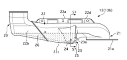
図3は吸気ダクト13を車両後方側から見た斜視図、図4は吸気ダクト13の平面図、図5は吸気ダクト13の背面図、図6は吸気ダクト13の底面図、図7は図5のS7-S7断面図である。
(Intake duct structure)
Next, the structure of the
3 is a perspective view of the
吸気ダクト13は、熱可塑性樹脂をブロー成形し、左右両端に開口部18,19を有して車幅方向へ延びる筒状に形成されている。吸気ダクト13の左端部20は上方へ屈曲し、第1端部13aの形状に応じた略矩形状に形成されている。吸気ダクト13の右端部21は下方へ屈曲し、ブロワ14の形状に応じた略円形状に形成されている。
吸気ダクト13において、左右端部20,21との間であって車幅方向へ延在する中央部22の上面22dの正面22e側には、吸気ダクト13を車体側のブラケット(不図示)にクリップ締結するためのフランジ部22aが形成されている。また、右端部21の先端には、ブロワ14とクリップ締結するためのフランジ部21aが形成されている。
図5に示すように、中央部22の内部には、車室内から吸気ダクト13へ浸入した液体を貯留可能な水溜部26が形成されている。図5の破線は、水溜部26に貯留した液体が貯留限界に達したときの水位を示すものである。
The
In the
As shown in FIG. 5, a
中央部22の背面22bであって、車幅方向中央位置には、背面22bからフロントトランクトリム9側に突出し、フロントトランクトリム9の壁面9aに近接する膨出部23が設けられている。膨出部23において、平面9aと対向するドレン孔形成面(排水孔形成面)23aには、壁面9aと対面するドレン孔(排水孔)24が形成されている。ドレン孔24の上下方向位置は、図5に示した水溜部26の貯留限界時の水位よりも低い位置に設定されている。
図7に示すように、膨出部23のドレン孔形成面23aは、上方を向いて傾斜している。一方、フロントトランクトリム9の壁面9aは、鉛直方向に立設されている。また、膨出部23の底面23bおよび底面23bに連続する中央部22の底面22cは、吸気ダクト13の背面22b側から見て、ドレン孔24の下方が最下端となる略U字形状に形成されている。
中央部22の底面22cは、中央部22の長さ方向、すなわち、車幅方向へ延びる突条25が設けられている。この突条25は、できるだけ膨出部23寄りの位置に設けるのが好ましい。また、膨出部23の底面23bに設けてもよい。
A bulging
As shown in FIG. 7, the drain
The
次に、作用を説明する。
[吸気ダクトへの液体の浸入抑制作用]
実施例1のバッテリ冷却装置1は、ブロワ14を回転駆動すると、車室内空気が吸気口12から吸気ダクト13へ吸入され、バッテリ2の筐体内に冷却風が供給されることで、筐体内のバッテリモジュールを冷却できる。車室内空気は、乗員によって常に快適な温度に設定されているため、特に夏季において、外気よりも好条件(低温)の冷却風でバッテリ2を冷却できる。
ここで、車室内空気を取り入れる吸気口12は室内トリム7に配置されているため、例えば、乗員が誤って飲料水等の液体を室内トリム7にこぼした場合、吸気ダクト13に流入した液体がバッテリ2へ浸入するおそれがある。
Next, the operation will be described.
[Inhibition of liquid intrusion into intake duct]
In the battery cooling device 1 according to the first embodiment, when the
Here, since the
この対策として、従来の発熱体冷却装置では、吸気ダクトの途中に液体をトラップする水溜部を設けている。ところが、水溜部の貯留限界を超える大量の液体が流入した場合、液体が水溜部を超えてバッテリに到達してしまう。なお、貯留限界を超えない場合であっても、水溜部に大量の水が貯留されていると、車室内空気で吹き上げられた液体が水溜部を超えてバッテリに到達することも懸念される。
また、従来の発熱体冷却装置では、水溜部に水抜き用のドレンボルトを設け、必要に応じて水溜部から液体を排出可能な構造を採用している。ところが、ドレンボルトによる水抜きは、吸気ダクトへの液体の流入と同時に行うことができない。よって、上述したように大量の液体が流入した場合には対応できない。また、水抜き作業を強いられるというデメリットもある。
As a countermeasure against this, in the conventional heating element cooling device, a water reservoir for trapping liquid is provided in the middle of the intake duct. However, when a large amount of liquid exceeding the storage limit of the water reservoir flows, the liquid reaches the battery beyond the water reservoir. Even if the storage limit is not exceeded, if a large amount of water is stored in the water reservoir, there is a concern that the liquid blown up by the air in the passenger compartment reaches the battery beyond the water reservoir.
Moreover, in the conventional heat generating body cooling device, the drain bolt for draining is provided in the water reservoir part, and the structure which can discharge | emit a liquid from a water reservoir part as needed is employ | adopted. However, drainage with a drain bolt cannot be performed simultaneously with the inflow of liquid into the intake duct. Therefore, as described above, it cannot cope with a large amount of liquid flowing in. In addition, there is a demerit that it is forced to drain water.
ここで、ドレンボルトを常に抜いておくことで、吸気ダクトへの液体の流入と同時に水抜きを行うことができるが、吸気ダクトから流出した液体が直接バッテリにかかるため、好ましくない。バッテリモジュールは、筐体に収容されており、ある程度の防水性能を有するが、液体が直接かかるような条件下で使用する場合、筐体のシール性を高める必要があり、コストアップにつながるからである。
ドレンボルトに代えて排水パイプを設け、水溜部からバッテリ収容空間の外部に水抜きを行う方法が考えられるが、車体側の追加加工(排水パイプを配策する加工)を要し、部品点数も増加するため、コストアップを招く。
Here, by always pulling out the drain bolt, water can be drained simultaneously with the inflow of liquid into the intake duct, but this is not preferable because the liquid flowing out from the intake duct is directly applied to the battery. The battery module is housed in the housing and has a certain level of waterproof performance, but when used under conditions where liquid is directly applied, it is necessary to improve the sealing performance of the housing, leading to an increase in cost. is there.
A drain pipe can be provided instead of a drain bolt, and water can be drained from the water reservoir to the outside of the battery housing space. However, additional processing on the vehicle body (processing to arrange the drain pipe) is required, and the number of parts is also reduced. This increases the cost.
これに対し、実施例1のバッテリ冷却装置1では、吸気ダクト13にフロントトランクトリム9の壁面9aと近接する膨出部23を設け、膨出部23に壁面9aに対面するドレン孔24を形成した。よって、吸気ダクト13に流入した液体は、図8の矢印Aで示すように、ドレン孔24から吸気ダクト13の外部へ流出した後、壁面9aを伝って下方へ流れ、フロントトランクトリム9の下端からトランクルーム4の下部空間4bへと排出される。
すなわち、実施例1では、バッテリ収容空間5とトランクルーム4とを仕切るフロントトランクトリム9の壁面9aを排水ルートとして利用することにより、排水パイプを別途設けることなく、吸気ダクト13に流入した液体をバッテリ収容空間5の外部へ排出できる。また、ドレン孔24から流出した液体がバッテリ2に直接かかるのを抑制できるため、バッテリ2の防水性能を低く抑え、コスト低減を図ることができる。
On the other hand, in the battery cooling device 1 according to the first embodiment, the
That is, in the first embodiment, by using the
上記のように壁面9aを排水ルートとして利用するためには、ドレン孔24を壁面9aに接近させることが必要である。ところが、吸気ダクト13は、バッテリ収容空間5の中央に配置されているため、従来形状の吸気ダクト13にドレン孔24を形成しただけでは、ドレン孔24から流出した液体が壁面9aまで届かない。そこで、実施例1では、吸気ダクト13に壁面9a側に突出する膨出部23を設け、この膨出部23にドレン孔24を形成することで、吸気ダクト13の位置はそのままでドレン孔24を壁面9aに接近させることができ、壁面9aを排水ルートとして利用することが可能となった。
よって、実施例1のバッテリ冷却装置1では、吸気口12から吸気ダクト13に大量の液体が流入した場合であっても、液体を水溜部26に貯留しつつ、ドレン孔24から排水できる。このため、従来の発熱体冷却装置と比較して、バッテリ2への液体の浸入をより抑制できる。また、追加部品および車体の加工も不要であるため、コスト面でも優れている。
In order to use the
Therefore, in the battery cooling device 1 according to the first embodiment, even when a large amount of liquid flows into the
実施例1では、バッテリ収容空間5を画成する左右前後の4つの壁面(サイドトランクトリム28a,28bの壁面、室内パネル8の壁面、フロントトランクトリム9の壁面9a)のうち、フロントトランクトリム9の壁面9aを排水ルートとしている。バッテリ2の左右には後輪のタイヤハウスが存在するため、吸気ダクト13からサイドトランクトリム28a,28bまでの距離は、室内パネル8またはフロントトランクトリム9までの距離と比較して非常に長くなる。よって、サイドトランクトリム28a,28bの壁面を排水ルートとした場合、膨出部23の大型化を招く。また、室内パネル8の壁面を排水ルートとした場合、壁面から落下した液体がバッテリ収容空間5に滞留してしまう。これに対し、実施例1のようにフロントトランクトリム9の壁面9aを排水ルートとした場合、膨出部23の小型化とバッテリ収容空間5の外部への排水を共に実現でき、排水ルートとして最も適している。
In the first embodiment, the front trunk trim 9 out of the four left and right wall surfaces (the wall surfaces of the side trunk trims 28a and 28b, the wall surface of the indoor panel 8, and the
[排水性能維持作用]
実施例1では、ドレン孔24を形成した膨出部23のドレン孔形成面23aを、壁面9aに対して傾斜させている。上述したように、バッテリ冷却装置1では、フロントトランクトリム9の壁面9aを排水ルートとして利用しているため、ドレン孔24はできるだけ壁面9aに接近させる必要がある。このとき、各部品の寸法誤差や組み付け誤差、変形によって、ドレン孔形成面23aと壁面9aとが接触した状態で吸気ダクト13が組み付けられることが考えられる。ここで、仮にドレン孔形成面23aと壁面9aとが互いに平行である場合、ドレン孔24が壁面9aにより塞がれ、液体の排出が阻害される。
そこで、実施例1では、膨出部23のドレン孔形成面23a、すなわち、ドレン孔24の周囲を壁面9aに対して傾斜させておくことで、ドレン孔形成面23aと壁面9aとが接触した状態で吸気ダクト13が組み付けられた場合であっても、ドレン孔24と壁面9aとの隙間を確保でき、所望の排水性能を維持できる。
[Drainage performance maintenance]
In Example 1, the drain
Therefore, in Example 1, the drain
[液体の飛散防止作用]
実施例1では、膨出部23の底面23bおよび底面23bに連続する中央部22の底面22cを、ドレン孔24側、すなわち吸気ダクト13を背面22b側から見たとき、ドレン孔24の下方が最下端となる略U字形状に形成した。吸気ダクト13内の液体がドレン孔24から流出する際、液体の一部は、ドレン孔形成面23aを伝って膨出部23の底面23bおよび中央部22の底面22cの最下端まで移動し、落下する。このとき、ドレン孔24の下方に底面23b,22cの最下端を設定しておくことで、底面23b,22cを伝う液体をドレン孔24の直下に落下させることができる。つまり、車幅方向における液体の落下位置を規定でき、落下位置が車幅方向に分散することに伴う液体のバッテリ2への付着を抑制できる。
[Liquid splash prevention]
In the first embodiment, when the
また、実施例1では、吸気ダクト13の底面22cに車幅方向に延在する突条25を設けた。このため、図8の矢印Bで示すように、ドレン孔24からドレン孔形成面23aに垂れ、底面23bの最下端を伝って底面23bを車両前方側へ移動する液体を、突条25によって強制的に落下させることができる。つまり、液体の車両前後方向の落下位置を、突条25の手前側(突条25よりも車両後方側)に規制できるため、落下位置が車両前後方向に分散することに伴う液体のバッテリ2への付着を抑制できる。
In the first embodiment, the
次に、効果を説明する。
実施例1のバッテリ冷却装置1にあっては、以下に列挙する効果を奏する。
(1) 吸気ダクト13に、バッテリ収容空間5を画成するフロントトランクトリム9の壁面9aに近接する膨出部23を設け、この膨出部23に壁面9aと対面するドレン孔24を形成した。これにより、吸気ダクト13に浸入した液体をドレン孔24から吸気ダクト13の外へ流出させた後、壁面9aを伝わせて下方へ排出できるため、バッテリ2への液体の浸入を抑制できる。
(2) バッテリ収容空間5を、車室内6とトランクルーム4との間の空間とし、壁面9aを、フロントトランクトリム9とした。これにより、ドレン孔24から流出した液体をトランクルーム4の下部空間4b、すなわち、バッテリ収容空間5の外部へ排出できるため、ドレン孔24から流出した液体がバッテリ2に付着するのを抑制できる。よって、バッテリ2の防水性能を低く抑えることができ、コスト低減を図ることができる。
Next, the effect will be described.
The battery cooling device 1 according to the first embodiment has the following effects.
(1) The
(2) The
(3) 膨出部23のドレン孔形成面23aと壁面9aとを互いに傾斜させたため、ドレン孔形成面23aと壁面9aとが接触した状態で吸気ダクト13が組み付けられた場合であっても、ドレン孔24と壁面9aとの隙間を確保でき、排水性能を維持できる。
(4) 膨出部23は、背面22b側から見てドレン孔24の下方が最下端となる略U字形状の底面23bを有するため、底面23bを伝う液体の車幅方向における落下位置を規定でき、落下位置が車幅方向に分散することに伴う液体のバッテリ2への付着を抑制できる。
(5) 吸気ダクト13の底面22cに車幅方向へ延びる突条25を設けたため、底面23b,22cを伝う液体の車両前後方向における落下位置を規定でき、落下位置が車両前後方向に分散することに伴う液体のバッテリ2への付着を抑制できる。
(3) Since the drain
(4) Since the bulging
(5) Since the
〔他の実施例〕
以上、本発明の発熱体冷却装置を実施するための形態を、実施例1に基づいて説明したが、本発明の具体的な構成は実施例に限定されず、特許請求の範囲の各請求項に係る発明の要旨を逸脱しない限り、設計の変更や追加等は許容される。
例えば、膨出部23のドレン孔形成面23aを下方に向けて傾斜させてもよい。また、ドレン孔形成面23aを鉛直面とし、フロントトランクトリム9の壁面9aを傾斜させてもよい。さらに、ドレン孔形成面23aと壁面9aを共に傾斜させてもよい。
実施例1では、膨出部23の底面23bをドレン孔24側から見て略U字形状とする例を示したが、略V字形状としてもよい。
突条25の位置を、バッテリ2の後端よりも車両後方側に設定してもよい。このような構成とすることで、落下した液体が直接バッテリ2に付着するのを防止できる。
実施例1では、本発明の発熱体冷却装置を駆動用モータに電力を供給する強電バッテリの冷却装置に適用した例を示したが、インバータそのたの機器の冷却装置にも適用できる。
[Other Examples]
As mentioned above, although the form for implementing the heat generating body cooling device of this invention was demonstrated based on Example 1, the concrete structure of this invention is not limited to an Example, Each claim of a claim Design changes and additions are permitted without departing from the spirit of the invention.
For example, the drain
In the first embodiment, an example in which the
The position of the
In the first embodiment, the heating element cooling device of the present invention is applied to a cooling device for a high-power battery that supplies electric power to a drive motor.
1 バッテリ冷却装置(発熱体冷却装置)
2 強電バッテリ(発熱体)
5 バッテリ収容空間(発熱体収容空間)
9 フロントトランクトリム
9a 壁面
13 吸気ダクト(吸気管)
23 膨出部
24 ドレン孔(排水孔)
1 Battery cooling device (heating element cooling device)
2 High-power battery (heating element)
5 Battery storage space (heating element storage space)
9 Front trunk trim
9a Wall surface
13 Intake duct (intake pipe)
23 bulge
24 Drain hole (drainage hole)
Claims (5)
前記吸気管に、前記発熱体収容空間を画成する一壁面と近接する膨出部を設け、この膨出部に、前記壁面と対面する排水孔を形成したことを特徴とする発熱体冷却装置。 In the heating element cooling device that cools the heating element by the air in the passenger compartment that is taken into the heating element housing space via the intake pipe,
A heating element cooling device, wherein a bulging portion adjacent to a wall surface defining the heating element housing space is provided in the intake pipe, and a drainage hole facing the wall surface is formed in the bulging portion. .
前記発熱体収容空間を、車室内後席と荷室との間の空間とし、
前記壁面を、前記荷室側の壁面としたことを特徴とする発熱体冷却装置。 The heating element cooling device according to claim 1,
The heating element housing space is a space between the rear seat in the vehicle interior and the cargo compartment,
The heating element cooling device, wherein the wall surface is a wall surface on the cargo compartment side.
前記膨出部の排水孔形成面と前記壁面とを互いに傾斜させたことを特徴とする発熱体冷却装置。 In the heating element cooling device according to claim 1 or 2,
A heating element cooling device characterized in that a drain hole forming surface of the bulging portion and the wall surface are inclined with respect to each other.
前記膨出部は、前記排水孔側から見て略U字または略V字形状の底面形状を有することを特徴とする発熱体冷却装置。 The heating element cooling device according to any one of claims 1 to 3,
The heating element cooling device according to claim 1, wherein the bulging portion has a substantially U-shaped or substantially V-shaped bottom shape when viewed from the drain hole side.
前記吸気管の底面に、前記排水孔の軸方向と交わる方向へ延びる突条を設けたことを特徴とする発熱体冷却装置。 In the heating element cooling device according to any one of claims 1 to 4,
A heating element cooling device, wherein a protrusion extending in a direction crossing the axial direction of the drain hole is provided on the bottom surface of the intake pipe.
Priority Applications (4)
| Application Number | Priority Date | Filing Date | Title |
|---|---|---|---|
| JP2010062979A JP5473698B2 (en) | 2010-03-18 | 2010-03-18 | Heating element cooling device |
| CN201010509482.5A CN102189924B (en) | 2010-03-18 | 2010-10-14 | Heat-emitting element cooling apparatus |
| EP20110250264 EP2366569B1 (en) | 2010-03-18 | 2011-03-08 | Structure for cooling heating element |
| US13/044,929 US8430194B2 (en) | 2010-03-18 | 2011-03-10 | Structure for cooling heating element |
Applications Claiming Priority (1)
| Application Number | Priority Date | Filing Date | Title |
|---|---|---|---|
| JP2010062979A JP5473698B2 (en) | 2010-03-18 | 2010-03-18 | Heating element cooling device |
Publications (2)
| Publication Number | Publication Date |
|---|---|
| JP2011198575A true JP2011198575A (en) | 2011-10-06 |
| JP5473698B2 JP5473698B2 (en) | 2014-04-16 |
Family
ID=44201318
Family Applications (1)
| Application Number | Title | Priority Date | Filing Date |
|---|---|---|---|
| JP2010062979A Active JP5473698B2 (en) | 2010-03-18 | 2010-03-18 | Heating element cooling device |
Country Status (4)
| Country | Link |
|---|---|
| US (1) | US8430194B2 (en) |
| EP (1) | EP2366569B1 (en) |
| JP (1) | JP5473698B2 (en) |
| CN (1) | CN102189924B (en) |
Cited By (6)
| Publication number | Priority date | Publication date | Assignee | Title |
|---|---|---|---|---|
| EP2620997A1 (en) | 2012-01-24 | 2013-07-31 | Mitsubishi Jidosha Kogyo K.K. | Pouring structure for battery pack |
| JP2014080119A (en) * | 2012-10-17 | 2014-05-08 | Mazda Motor Corp | Vehicle rear structure |
| JP2014129039A (en) * | 2012-12-28 | 2014-07-10 | Toyota Motor Corp | Cooling device of battery |
| JP2016068598A (en) * | 2014-09-26 | 2016-05-09 | トヨタ自動車株式会社 | Intake duct |
| JP2021112943A (en) * | 2020-01-17 | 2021-08-05 | 株式会社イノアックコーポレーション | duct |
| FR3107859A1 (en) * | 2020-03-03 | 2021-09-10 | Alstom Transport Technologies | Air duct, ventilation device and associated vehicle |
Families Citing this family (16)
| Publication number | Priority date | Publication date | Assignee | Title |
|---|---|---|---|---|
| FR2948231B1 (en) * | 2009-07-17 | 2013-01-18 | Peugeot Citroen Automobiles Sa | MOTOR VEHICLE COMPRISING AN ELECTRIC MOTOR SUPPLIED BY A POWER SUPPLY MODULE |
| JP5574249B2 (en) * | 2010-05-26 | 2014-08-20 | スズキ株式会社 | Car body rear structure |
| JP2012096715A (en) * | 2010-11-04 | 2012-05-24 | Suzuki Motor Corp | Cooling duct structure for battery unit |
| FR2972143B1 (en) * | 2011-03-01 | 2013-09-20 | Renault Sa | SYSTEM FOR CONNECTING A POWER BATTERY TO A MOTOR VEHICLE |
| WO2013073465A1 (en) * | 2011-11-14 | 2013-05-23 | 本田技研工業株式会社 | Battery pack for electric vehicle, and battery pack mounting structure |
| US8813888B2 (en) * | 2012-02-06 | 2014-08-26 | Honda Motor Co., Ltd. | Vehicle body rear structure |
| JP5595442B2 (en) * | 2012-04-18 | 2014-09-24 | 本田技研工業株式会社 | Car power supply mounting structure |
| US9300017B2 (en) * | 2012-08-03 | 2016-03-29 | Ford Global Technologies, Llc | Detecting blockage of air flow through vehicle traction battery |
| CN104755296B (en) * | 2012-10-31 | 2017-04-05 | 本田技研工业株式会社 | Electric vehicle |
| JP5827615B2 (en) * | 2012-12-27 | 2015-12-02 | トヨタ紡織株式会社 | Exhaust structure for vehicles |
| GB2512278B (en) * | 2013-02-26 | 2017-07-12 | Mclaren Automotive Ltd | Cooling Vehicle Components |
| JP5942943B2 (en) * | 2013-08-20 | 2016-06-29 | トヨタ自動車株式会社 | Battery temperature control device |
| US9302573B2 (en) * | 2013-08-30 | 2016-04-05 | Ford Global Technologies, Llc | Duct for high voltage battery air cooling exhaust and recirculation |
| US9440509B2 (en) * | 2013-10-04 | 2016-09-13 | Ford Global Technologies, Llc | Battery cooling apparatus |
| US9387906B2 (en) * | 2014-09-10 | 2016-07-12 | Ford Global Technologies, Llc | Battery box for electric cycle |
| KR20220034608A (en) * | 2020-09-11 | 2022-03-18 | 현대모비스 주식회사 | Active Air Flap Apparatus For Vehicle |
Citations (7)
| Publication number | Priority date | Publication date | Assignee | Title |
|---|---|---|---|---|
| JPH10252467A (en) * | 1997-03-14 | 1998-09-22 | Toyota Motor Corp | Battery temperature adjusting device mounted on electric vehicle |
| JP2006134853A (en) * | 2004-10-08 | 2006-05-25 | Honda Motor Co Ltd | Battery box structure |
| JP2006228556A (en) * | 2005-02-17 | 2006-08-31 | Toyota Motor Corp | Cooling structure of secondary battery |
| JP2006224798A (en) * | 2005-02-17 | 2006-08-31 | Toyota Motor Corp | Cooling structure of electricity storage device |
| JP2008087665A (en) * | 2006-10-03 | 2008-04-17 | Toyota Motor Corp | Liquid discharge structure for air duct |
| JP2008097850A (en) * | 2006-10-06 | 2008-04-24 | Panasonic Ev Energy Co Ltd | Exhaust system and battery pack |
| JP2009154696A (en) * | 2007-12-26 | 2009-07-16 | Calsonic Kansei Corp | Cooling device for heating element |
Family Cites Families (13)
| Publication number | Priority date | Publication date | Assignee | Title |
|---|---|---|---|---|
| JP2575909B2 (en) * | 1990-01-22 | 1997-01-29 | 日産自動車株式会社 | Automotive air box structure |
| JPH07132859A (en) | 1993-11-10 | 1995-05-23 | Nissan Motor Co Ltd | Vehicle body floor structure |
| JPH07329552A (en) * | 1994-06-09 | 1995-12-19 | Zexel Corp | Drain discharge structure for air conditioner |
| JP4023450B2 (en) * | 2004-01-20 | 2007-12-19 | トヨタ自動車株式会社 | Cooling device for electrical equipment |
| KR100903182B1 (en) * | 2005-09-28 | 2009-06-17 | 주식회사 엘지화학 | Cooling System of Battery Pack for Vehicle |
| KR100802767B1 (en) * | 2005-11-04 | 2008-02-12 | 현대자동차주식회사 | Cooling system for a battery and motor control unit of a hybrid vehicle |
| JP4780050B2 (en) * | 2007-07-04 | 2011-09-28 | トヨタ自動車株式会社 | Battery cooling structure |
| KR20090062380A (en) * | 2007-12-13 | 2009-06-17 | 현대자동차주식회사 | Outlet duct of battery system for hybrid eletric vehicle |
| JP4283326B1 (en) * | 2007-12-25 | 2009-06-24 | 本田技研工業株式会社 | Battery cooling air intake structure |
| JP2009161062A (en) * | 2008-01-08 | 2009-07-23 | Calsonic Kansei Corp | Cooling system of heating element |
| TWI338642B (en) * | 2008-02-07 | 2011-03-11 | Honda Motor Co Ltd | Vehicular power supply system |
| JP5040905B2 (en) * | 2008-12-24 | 2012-10-03 | トヨタ自動車株式会社 | Temperature control structure of power storage device |
| US8276696B2 (en) * | 2010-07-27 | 2012-10-02 | Ford Global Technologies, Llc | Structural battery duct assembly |
-
2010
- 2010-03-18 JP JP2010062979A patent/JP5473698B2/en active Active
- 2010-10-14 CN CN201010509482.5A patent/CN102189924B/en not_active Expired - Fee Related
-
2011
- 2011-03-08 EP EP20110250264 patent/EP2366569B1/en not_active Not-in-force
- 2011-03-10 US US13/044,929 patent/US8430194B2/en active Active
Patent Citations (7)
| Publication number | Priority date | Publication date | Assignee | Title |
|---|---|---|---|---|
| JPH10252467A (en) * | 1997-03-14 | 1998-09-22 | Toyota Motor Corp | Battery temperature adjusting device mounted on electric vehicle |
| JP2006134853A (en) * | 2004-10-08 | 2006-05-25 | Honda Motor Co Ltd | Battery box structure |
| JP2006228556A (en) * | 2005-02-17 | 2006-08-31 | Toyota Motor Corp | Cooling structure of secondary battery |
| JP2006224798A (en) * | 2005-02-17 | 2006-08-31 | Toyota Motor Corp | Cooling structure of electricity storage device |
| JP2008087665A (en) * | 2006-10-03 | 2008-04-17 | Toyota Motor Corp | Liquid discharge structure for air duct |
| JP2008097850A (en) * | 2006-10-06 | 2008-04-24 | Panasonic Ev Energy Co Ltd | Exhaust system and battery pack |
| JP2009154696A (en) * | 2007-12-26 | 2009-07-16 | Calsonic Kansei Corp | Cooling device for heating element |
Cited By (8)
| Publication number | Priority date | Publication date | Assignee | Title |
|---|---|---|---|---|
| EP2620997A1 (en) | 2012-01-24 | 2013-07-31 | Mitsubishi Jidosha Kogyo K.K. | Pouring structure for battery pack |
| JP2013152806A (en) * | 2012-01-24 | 2013-08-08 | Mitsubishi Motors Corp | Water injection structure of battery pack |
| JP2014080119A (en) * | 2012-10-17 | 2014-05-08 | Mazda Motor Corp | Vehicle rear structure |
| JP2014129039A (en) * | 2012-12-28 | 2014-07-10 | Toyota Motor Corp | Cooling device of battery |
| JP2016068598A (en) * | 2014-09-26 | 2016-05-09 | トヨタ自動車株式会社 | Intake duct |
| JP2021112943A (en) * | 2020-01-17 | 2021-08-05 | 株式会社イノアックコーポレーション | duct |
| JP7374777B2 (en) | 2020-01-17 | 2023-11-07 | 株式会社イノアックコーポレーション | duct |
| FR3107859A1 (en) * | 2020-03-03 | 2021-09-10 | Alstom Transport Technologies | Air duct, ventilation device and associated vehicle |
Also Published As
| Publication number | Publication date |
|---|---|
| EP2366569B1 (en) | 2014-04-30 |
| US8430194B2 (en) | 2013-04-30 |
| CN102189924B (en) | 2015-08-26 |
| EP2366569A1 (en) | 2011-09-21 |
| CN102189924A (en) | 2011-09-21 |
| US20110226441A1 (en) | 2011-09-22 |
| JP5473698B2 (en) | 2014-04-16 |
Similar Documents
| Publication | Publication Date | Title |
|---|---|---|
| JP5473698B2 (en) | Heating element cooling device | |
| KR101085278B1 (en) | Electric power source device for vehicle | |
| JP4919102B2 (en) | Cooling structure for power supply unit for vehicle | |
| US7976097B2 (en) | Cowl structure of vehicle | |
| JP6035967B2 (en) | Battery pack for vehicles | |
| JP5434662B2 (en) | Drainage structure for vehicle battery unit | |
| JP2016153279A (en) | Cooling unit of vehicular battery pack | |
| JP2009154826A (en) | Ventilation structure of battery storage part | |
| US10189343B2 (en) | Case structure of power equipment unit | |
| CN102864807A (en) | Hybrid working vehicle | |
| JP2011194988A (en) | Cooling device for heat-emitting body | |
| CN109305030B (en) | Automatic grille | |
| CN106794744B (en) | Motor vehicle with a cooled equipment compartment located inside the vehicle body | |
| JP5057037B2 (en) | Battery arrangement structure for automobiles | |
| JP2016199105A (en) | Battery unit | |
| CN114248611A (en) | Battery case mounting structure for electric vehicle | |
| JP6440018B2 (en) | Battery unit box vent cover | |
| JP4725270B2 (en) | Structure of cooling device for power control unit | |
| WO2011149077A1 (en) | Battery-containing case and vehicle with said case on board | |
| JP2014043225A (en) | Cooling structure of vehicle battery pack | |
| JP6530932B2 (en) | vehicle | |
| US11498404B2 (en) | Battery storage device for electric vehicle | |
| KR101804196B1 (en) | Package-storage-type engine power generator | |
| JP5272852B2 (en) | Battery structure for electric vehicles | |
| JP6225686B2 (en) | Battery cooling system |
Legal Events
| Date | Code | Title | Description |
|---|---|---|---|
| A621 | Written request for application examination |
Free format text: JAPANESE INTERMEDIATE CODE: A621 Effective date: 20120920 |
|
| A977 | Report on retrieval |
Free format text: JAPANESE INTERMEDIATE CODE: A971007 Effective date: 20131024 |
|
| A131 | Notification of reasons for refusal |
Free format text: JAPANESE INTERMEDIATE CODE: A131 Effective date: 20131105 |
|
| A521 | Request for written amendment filed |
Free format text: JAPANESE INTERMEDIATE CODE: A523 Effective date: 20131225 |
|
| TRDD | Decision of grant or rejection written | ||
| A01 | Written decision to grant a patent or to grant a registration (utility model) |
Free format text: JAPANESE INTERMEDIATE CODE: A01 Effective date: 20140204 |
|
| A61 | First payment of annual fees (during grant procedure) |
Free format text: JAPANESE INTERMEDIATE CODE: A61 Effective date: 20140204 |
|
| R150 | Certificate of patent or registration of utility model |
Free format text: JAPANESE INTERMEDIATE CODE: R150 Ref document number: 5473698 Country of ref document: JP Free format text: JAPANESE INTERMEDIATE CODE: R150 |
|
| R250 | Receipt of annual fees |
Free format text: JAPANESE INTERMEDIATE CODE: R250 |
|
| R250 | Receipt of annual fees |
Free format text: JAPANESE INTERMEDIATE CODE: R250 |
|
| R250 | Receipt of annual fees |
Free format text: JAPANESE INTERMEDIATE CODE: R250 |
|
| R250 | Receipt of annual fees |
Free format text: JAPANESE INTERMEDIATE CODE: R250 |
|
| R250 | Receipt of annual fees |
Free format text: JAPANESE INTERMEDIATE CODE: R250 |
|
| S111 | Request for change of ownership or part of ownership |
Free format text: JAPANESE INTERMEDIATE CODE: R313113 |
|
| S533 | Written request for registration of change of name |
Free format text: JAPANESE INTERMEDIATE CODE: R313533 |
|
| R350 | Written notification of registration of transfer |
Free format text: JAPANESE INTERMEDIATE CODE: R350 |
|
| S533 | Written request for registration of change of name |
Free format text: JAPANESE INTERMEDIATE CODE: R313533 |
|
| R350 | Written notification of registration of transfer |
Free format text: JAPANESE INTERMEDIATE CODE: R350 |
|
| R250 | Receipt of annual fees |
Free format text: JAPANESE INTERMEDIATE CODE: R250 |
|
| R250 | Receipt of annual fees |
Free format text: JAPANESE INTERMEDIATE CODE: R250 |