JP2011197319A - Image forming system - Google Patents
Image forming system Download PDFInfo
- Publication number
- JP2011197319A JP2011197319A JP2010063239A JP2010063239A JP2011197319A JP 2011197319 A JP2011197319 A JP 2011197319A JP 2010063239 A JP2010063239 A JP 2010063239A JP 2010063239 A JP2010063239 A JP 2010063239A JP 2011197319 A JP2011197319 A JP 2011197319A
- Authority
- JP
- Japan
- Prior art keywords
- image forming
- image
- fixing
- forming apparatus
- toner image
- Prior art date
- Legal status (The legal status is an assumption and is not a legal conclusion. Google has not performed a legal analysis and makes no representation as to the accuracy of the status listed.)
- Withdrawn
Links
Images
Landscapes
- Fixing For Electrophotography (AREA)
- Color Electrophotography (AREA)
Abstract
【課題】本発明は、透明トナー像を必要とないユーザーに対してはコストを負担させず、透明トナー像を必要とするユーザーに対しては、同一画像内で光沢差を付与することができる画像形成システムを提供できる。
【解決手段】用紙P上にカラートナー像を作像するプロセスユニット10Y、M、C、K、及び用紙上のカラートナー像を加熱定着する第一定着装置26を有する第一画像形成装置1と、第一画像形成装置1によって出力された用紙Pに連続して透明トナー像を作像するプロセスユニット30及び用紙P上のカラートナー像及び透明トナー像を加熱定着する第二定着装置37を有する第二画像形成装置2とを備え、第一画像形成装置1に対して第二画像形成装置2がオプション搭載される画像形成システムにおいて、第一定着装置26における定着温度よりも第二定着装置37における定着温度が低い。
【選択図】図1The present invention does not incur a cost for a user who does not need a transparent toner image, and can give a gloss difference within the same image to a user who needs a transparent toner image. An image forming system can be provided.
A first image forming apparatus having a process unit (10Y, M, C, K) for forming a color toner image on a paper (P) and a first fixing device (26) for fixing the color toner image on the paper by heating. A process unit 30 that continuously forms a transparent toner image on the paper P output by the first image forming apparatus 1 and a second fixing device 37 that heat-fixes the color toner image and the transparent toner image on the paper P. In the image forming system including the second image forming apparatus 2 having the second image forming apparatus 2 as an option with respect to the first image forming apparatus 1, the second fixing temperature is higher than the fixing temperature in the first fixing apparatus 26. The fixing temperature in the device 37 is low.
[Selection] Figure 1
Description
本発明は電子写真方式を用いてトナー像を作像する第一画像形成装置に対して透明トナー像を作像する第二画像形成装置をオプション搭載可能な画像形成システムに関するものである。 The present invention relates to an image forming system in which a second image forming apparatus for forming a transparent toner image can be optionally mounted on a first image forming apparatus for forming a toner image using an electrophotographic system.
画質の多様化が進められている近年においては、光沢感、立体感など、通常のトナーの使用では得ることができない特殊な画質を実現しうる画像形成装置が種々提案されている。 In recent years when image quality has been diversified, various image forming apparatuses have been proposed that can realize special image quality that cannot be obtained by using normal toner, such as glossiness and stereoscopic effect.
例えば、特許文献1では、転写材上にブラック、イエロー、マゼンタ、シアンといった通常の有色トナー像と共に透明トナー像を転写・定着する画像形成装置が提案されている。この画像形成装置によれば、用紙全体に透明樹脂をスプレーしたり、コーティングしたりするものに比べて複雑な機構を組み込む必要がなく、普通紙等を用いても見栄えのよい光沢感のある画像を容易に得ることができる。 For example, Patent Document 1 proposes an image forming apparatus that transfers and fixes a transparent toner image together with normal colored toner images such as black, yellow, magenta, and cyan on a transfer material. According to this image forming apparatus, it is not necessary to incorporate a complicated mechanism as compared with the case where a transparent resin is sprayed or coated on the entire paper, and a glossy image that looks good even if plain paper is used. Can be easily obtained.
また、特許文献2では、転写材上に有色トナー像を転写・定着した後に、透明トナー像を転写・定着する画像形成装置が提案されている。この画像形成装置では、有色トナー像が転写・定着された転写材を転写材搬送経路を通して再給紙し、転写材上の有色トナー像上に透明トナー像を転写した後、先と同じ定着装置により定着して画像を出力する。この画像形成装置によれば、有色トナー像と透明トナー像とを重ね合わせて形成する際の色にじみが生じることを防止するとともに、光沢度の向上を図っている。さらに、有色トナー像の定着時よりも透明トナー像の定着時の定着性を上げる、例えば転写材の搬送速度を遅くすることで光沢度の向上を図っている。
しかしながら、特許文献1に提案される画像形成装置にあっては、転写材上に有色トナー像と透明トナー像の全てを転写した後に定着を行うために、同一画像内で光沢差を付けることは困難である。特許文献2に記載される画像形成装置にあっても、同一画像内で光沢差を付けることは困難である。透明トナー像定着時の定着性を上げることにより光沢感の向上を図っているが、透明トナー像と同様に有色トナー像の光沢感も一様に向上するため、同一画像内で光沢感が部分的に変化することはないからである。
However, in the image forming apparatus proposed in Patent Document 1, it is not possible to give a gloss difference in the same image in order to perform fixing after transferring all of the colored toner image and the transparent toner image onto the transfer material. Have difficulty. Even in the image forming apparatus described in
これに対し、特許文献3では、有色トナー像及び/又は透明トナー像を転写材上に転写・定着した後、透明トナー像を転写材上に転写・定着する画像形成装置が提案されている。この画像形成装置では、一回目の定着工程における定着ニップ内でのトナーの到達溶融粘度η1と、二回目の定着工程における定着ニップ内でのトナーの到達溶融粘度η2が、(到達溶融粘度η1)<(到達溶融粘度η2)の関係を満足している。これにより、二回目の定着工程における透明トナー像の溶融状態を一回目の定着工程よりも抑えることができるので、二回目の画像形成工程で得られる透明トナー像を一回目の画像形成工程で得られる透明トナー像に比べ低光沢部とすることができる。つまり、同一画像面内での任意の部分に対し、高光沢部及び低光沢部を出力可能である。 On the other hand, Patent Document 3 proposes an image forming apparatus in which a color toner image and / or a transparent toner image is transferred and fixed on a transfer material, and then the transparent toner image is transferred and fixed on the transfer material. In this image forming apparatus, the ultimate melt viscosity η1 of the toner in the fixing nip in the first fixing step and the ultimate melt viscosity η2 of the toner in the fixing nip in the second fixing step are (final melt viscosity η1). <(Achieved melt viscosity η2) is satisfied. As a result, the melting state of the transparent toner image in the second fixing step can be suppressed more than in the first fixing step, so that the transparent toner image obtained in the second image forming step can be obtained in the first image forming step. Compared to a transparent toner image to be produced, a low gloss portion can be obtained. That is, it is possible to output a high gloss portion and a low gloss portion for an arbitrary portion within the same image plane.
なお、特許文献4では、後述する課題を解決するための手段における「第一画像形成装置に対してオプション搭載可能な第二画像形成装置」と同様に、「画像形成本体部に付設された特殊トナー像を形成し得る副機能付加ユニット」が開示されている。この画像形成装置では、特殊トナー像を所望しないユーザーに対しては、副機能付加ユニットを付設しない構成をとることができ、余計なコストを負担させることがない。しかしながら、この副機能付加ユニットは、熱発泡性トナーを用いることにより立体感のある画像を得ることを目的とするものである。そのため、副機能付加ユニットでの定着温度が画像形成本体部の定着温度よりも高く設定されている。よって、この付記機能付加ユニットで特殊トナーとして透明トナーを用いた場合には、透明トナー像と有色トナー像との光沢感が一様となり、同一画像内で光沢感を部分的に変化させて出力することは困難である。 In Patent Document 4, as in “Second image forming apparatus that can be optionally mounted on the first image forming apparatus” in the means for solving the problems described later, “special attached to the image forming main body”. A sub-function addition unit capable of forming a toner image is disclosed. In this image forming apparatus, a user who does not desire a special toner image can be configured not to be provided with a sub-function adding unit, and an extra cost is not borne. However, the purpose of this sub-function addition unit is to obtain a three-dimensional image by using a thermally foamable toner. Therefore, the fixing temperature in the sub-function adding unit is set higher than the fixing temperature of the image forming main body. Therefore, when transparent toner is used as the special toner in this additional function addition unit, the glossiness of the transparent toner image and the colored toner image becomes uniform, and the glossiness is partially changed in the same image for output. It is difficult to do.
特許文献3に提案される画像形成装置は、高光沢部及び低光沢部を出力可能であるものの、同一画像形成装置内に、少なくともイエロー・シアン、マゼンタ・ブラック・透明トナーの5つ以上の現像装置及び感光体ドラムを備えたタンデム方式となってしまい、生産コストが非常に高くなってしまう。5つ以上の現像機を備えたリボルバー方式でも同様に生産コストが非常に高くなってしまう。透明トナーを必要とするユーザーは増加しているものの、ほとんどのユーザーにとって、出力画像はモノクロもしくは4色のフルカラー画像のみであるため、全ての画像形成装置に対してあらかじめ透明トナーでの画像形成を可能とするのはコスト高となり適切でない。 Although the image forming apparatus proposed in Patent Document 3 can output a high gloss part and a low gloss part, at least five developments of at least yellow, cyan, magenta, black, and transparent toner in the same image forming apparatus. The tandem system including the apparatus and the photosensitive drum is used, and the production cost becomes very high. Similarly, the revolver system having five or more developing machines also has a very high production cost. Although the number of users who need transparent toner is increasing, for most users, the output image is only a monochrome or four-color full-color image. Making it possible is not appropriate due to high costs.
本発明は以上の問題点に鑑みなされたものである。その目的は、透明トナー像を必要とないユーザーに対してはコストを負担させず、透明トナー像を必要とするユーザーに対しては、同一画像内で光沢差を付与することができる画像形成システムを提供することである。 The present invention has been made in view of the above problems. The purpose of the image forming system is that it does not incur a cost for a user who does not need a transparent toner image, and can give a gloss difference within the same image to a user who needs a transparent toner image. Is to provide.
上記課題を解決するため、請求項1の発明は、記録媒体上に有色トナー像を作像する作像手段、及び記録媒体上の有色トナー像を加熱定着する第一定着手段を有する第一画像形成装置と、第一画像形成装置によって出力された記録媒体に連続して透明トナー像を作像する第二作像手段、及び記録媒体上の有色トナー像及び透明トナー像を加熱定着する第二定着手段を有する第二画像形成装置とを備え、該第一画像形成装置に対して該第二画像形成装置がオプション搭載される画像形成システムにおいて、第一定着手段における定着温度よりも第二定着手段における定着温度が低いことを特徴とするものである。
請求項2の発明は、請求項1の画像形成システムにおいて、上記第一定着手段よりも記録媒体移動方向下流側で、且つ上記第二定着手段よりも記録媒体移動方向上流側で、上記記録媒体の温度を検出する記録媒体温度検出手段を備え、該第二定着手段は、該記録媒体温度検出手段からの検出結果に基づき、定着温度を制御することを特徴とするものである。
請求項3の発明は、請求項1又は2の画像形成システムにおいて、上記第二作像手段は、作像時に排出されるトナーを再利用するためのトナー再利用機構を備えることを特徴とするものである。
請求項4の発明は、請求項1、2又は3の画像形成システムにおいて、上記記録媒体の両面に画像形成を行う場合には、上記第一画像形成装置で該記録媒体の両面に有色トナー像を転写定着した後に、上記第二画像形成装置で該記録媒体の両面に透明トナー像を転写定着させることを特徴とするものである。
本発明において、トナー像は高い定着温度で十分に溶融させると、表面の平滑性が向上し光沢度が高くなり、低い定着温度であまり溶融させないと、表面が粗く光が乱反射して光沢度が低下する。よって、第一定着手段で高い第一定着温度で定着された有色トナー像は光沢度が高く、第二定着手段で低い第二定着温度で定着された透明トナー像は光沢度が低いものとなり、同一画像内で光沢差が生じる。なお、高い定着温度で定着され高い光沢度をもったトナー像は、その後低い定着温度で定着される工程を経ても高い光沢を保ったままである。
In order to solve the above problems, the invention of claim 1 includes a first image forming means for forming a colored toner image on a recording medium, and a first fixing means for heating and fixing the colored toner image on the recording medium. An image forming apparatus; a second image forming unit that continuously forms a transparent toner image on the recording medium output by the first image forming apparatus; and a first image forming apparatus that heat-fixes the colored toner image and the transparent toner image on the recording medium. And an image forming system in which the second image forming apparatus is optionally mounted on the first image forming apparatus. The fixing temperature in the two fixing means is low.
According to a second aspect of the present invention, in the image forming system of the first aspect, the recording is performed on the downstream side in the recording medium movement direction from the first fixing unit and on the upstream side in the recording medium movement direction from the second fixing unit. The recording medium temperature detecting means for detecting the temperature of the medium is provided, and the second fixing means controls the fixing temperature based on the detection result from the recording medium temperature detecting means.
According to a third aspect of the present invention, in the image forming system according to the first or second aspect, the second image forming unit includes a toner reuse mechanism for reusing toner discharged at the time of image formation. Is.
According to a fourth aspect of the present invention, in the image forming system according to the first, second, or third aspect, when image formation is performed on both sides of the recording medium, the first image forming apparatus uses a colored toner image on both sides of the recording medium. After the toner is transferred and fixed, the second image forming apparatus transfers and fixes a transparent toner image on both surfaces of the recording medium.
In the present invention, when the toner image is sufficiently melted at a high fixing temperature, the smoothness of the surface is improved and the glossiness is increased. descend. Therefore, the colored toner image fixed at the high first fixing temperature by the first fixing means has high glossiness, and the transparent toner image fixed at the second fixing temperature low by the second fixing means has low glossiness. Thus, a difference in gloss occurs in the same image. A toner image that is fixed at a high fixing temperature and has a high glossiness remains high gloss even after a process of fixing at a low fixing temperature.
本発明は、透明トナー像を必要とないユーザーに対してはコストを負担させず、透明トナー像を必要とするユーザーに対しては、同一画像内で光沢差を付与することができる画像形成システムを提供できるという優れた効果がある。 The present invention does not incur a cost for a user who does not need a transparent toner image, and can provide a gloss difference within the same image to a user who needs a transparent toner image. There is an excellent effect that can be provided.
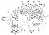
以下、本発明を適用した画像形成システムとして、電子写真方式によって画像を形成する画像形成システムの実施形態について説明する。図1は、本実施形態に係る画像形成システムを示す概略構成図である。この画像形成システムは、第一画像形成装置1と、これにオプション搭載される第二画像形成装置2とを有している。
Hereinafter, an embodiment of an image forming system that forms an image by an electrophotographic method will be described as an image forming system to which the present invention is applied. FIG. 1 is a schematic configuration diagram showing an image forming system according to the present embodiment. This image forming system includes a first image forming apparatus 1 and a second
まず、第一画像形成装置1の基本的な構成について説明する。第一画像形成装置1は、イエロー(Y),マゼンタ(M),シアン(C),ブラック(K)の有色トナー像を形成するための4つのプロセスユニット10Y,M,C,Kを備えている。以下添字Y、M、C、Kはイエロー、マゼンタ、シアン、ブラックの各色をそれぞれ示す。このプロセスユニット10Y、M、C、Kは、それぞれ各色のトナー像を担持する像担持体である感光体11Y,M,C,Kを備えている。これら各感光体11Y,M,C,Kの周囲には、各感光体11表面を一様に帯電する帯電装置12Y,M,C,Kや、一様に帯電された各感光体11表面を画像データに基づき露光して静電潜像を形成する露光装置13Y,M,C,K、各感光体11表面に形成される静電潜像を現像する現像装置14Y,M,C,K、トナー像転写後の各感光体11表面をクリーニングするクリーニング装置15Y,M,C,K等を備えている。なお、画像データとは、図示しない外付けのスキャナによる原稿読取で得られた画像情報や、外部のパーソナルコンピュータから送られている画像情報等である。また、プロセスユニット10Y,M,C,Kは、感光体11の周囲に配設される各種装置12、14、15とを1つのユニットとして共通の支持体に支持するものであり、第一画像形成装置1本体に対して着脱可能になっている。
First, the basic configuration of the first image forming apparatus 1 will be described. The first image forming apparatus 1 includes four
また、第一画像形成装置1は、感光体11Y,M,C,Kに形成された有色トナー画像を用紙Pに転写する転写ユニット20を備えている。この転写ユニット20は、駆動ローラを含む複数のローラにより張架されて図中矢印方向に回転駆動する中間転写ベルト21を備えている。中間転写ユニット20は、感光体11Y,M,C,Kと所定の電圧が印加される一次転写ローラ22Y,M,C,Kとの間に中間転写ベルト21を挟み込んで一次転写ニップを形成する。また、中間転写ユニット20は二次転写バックアップローラ23と所定の電圧が印加される二次転写ローラ24の間に中間転写ベルト21を挟み込んで二次転写ニップを形成している。さらに、中間転写ユニット20は、中間転写ベルト21上に残留する転写残トナーを除去する図示しないクリーニング装置等も備えている。上記プロセスユニット10Y,M,C,Kで形成された感光体11Y,M,C,K上の有色トナー像は、一次転写ニップで中間転写ベルト21に順次重ね合わされて一次転写される。中間転写ベルト21上に転写された4色重ね合わせ有色トナー像は、二次転写ニップで用紙Pに二次転写されることになる。
The first image forming apparatus 1 also includes a
また、第一画像形成装置1は、転写ユニット20の下方に、給紙カセット25、図示しないレジストローラ対、第一定着装置26、また第一画像形成装置1の筐体内で用紙Pを搬送する第一紙搬送路27等を備えている。給紙カセット25は、第一画像形成装置1の筺体内に出し入れ可能に構成され、収容する用紙Pの一番上の用紙を一枚づつレジストローラ対に向けて送り出す。レジストローラ対は、給紙カセット25により供給された用紙Pをローラ間に挟み込み、中間転写ベルト21上の4色重ね合わせ有色トナー像に同期させ得るタイミングで二次転写ニップに送り出す。第一定着装置26は、後述するように、ハロゲンランプ等の発熱源を内包する定着ローラ26aと、これに向けて押圧される加圧ローラ26bとの当接による定着ニップに用紙Pを挟み込み、加熱や加圧の作用によりトナー像を定着せしめる。第一紙搬送路27は、後述するように、給紙カセット25から給紙される用紙Pを二次転写ニップや第一定着装置26に案内するための第一転写定着用紙搬送路27aや、片面に対する転写定着処理を終えた用紙Pを図示しない切換爪で反転させ再び二次転写ニップに案内するための第一反転用紙搬送路27b等から構成される。
Further, the first image forming apparatus 1 conveys the paper P below the
次に、第二画像形成装置2の基本的な構成について説明する。第二画像形成装置2は、画像に対する光沢性付与処理を必要に応じて行うことを要望するユーザーの意志により、第一画像形成装置1に対してオプション搭載されるものである。
Next, a basic configuration of the second
この第二画像形成装置2は、透明トナー像を形成するためのプロセスユニット30を備えている。このプロセスユニット30は、ドラム状の感光体31の周囲に帯電装置32、露光装置33、現像装置34、転写ローラ36、クリーニング装置35などを有している。このプロセスユニット30の露光装置33は、帯電装置32によって一様に帯電された感光体31上の光沢性付与領域に対応する領域を露光装置によって露光してベタ状の静電潜像を形成する。現像装置34は、この静電潜像を透明トナーにより現像して透明トナー像を形成する。所定の電圧が印加される転写ローラ36は、感光体31との間に用紙Pを挟み込んで転写ニップを形成している。感光体31上に現像された透明トナー像は、転写ニップで用紙Pに転写されることになる。第一画像形成装置1のプロセスユニット10Y,M,C,Kが、通常の有色トナーを用いるのに対し、第二画像形成装置2のプロセスユニット30が透明トナーを用いる点以外は、第一画像形成装置1のものと第二画像形成装置2とは同様の構成である。透明トナーには、有色トナーに顔料成分を添加しないものが使用できる。
The second
また、第二画像形成装置2は、この他に、第二定着装置37、第二画像形成装置2内で用紙を搬送する第二紙搬送路等38等を備えている。上記第二定着装置37は、後述するように、ハロゲンランプ等の発熱源を内包する定着ローラ37aと、これに向けて押圧される加圧ローラ37bとの当接による定着ニップに用紙Pを挟み込み、加熱や加圧の作用によりトナー像を定着せしめる。本実施形態で用いられる透明トナーは、第二定着装置37による加熱定着処理を施される前には白色を帯びる白色トナーであるが、加熱定着処理を施されると透明トナーに変化する性質を有している。第二紙搬送路38は、第一画像形成装置1より排出される用紙Pをプロセスユニット30の転写ニップ及び第二定着装置37に案内するための第二転写定着用紙搬送路38a、片面に対する透明トナー像の転写定着処理を終えた用紙Pを図示しない切換爪で反転させ再度転写ニップに案内するための第二反転用紙搬送路38b、第一画像形成装置1より排出される用紙Pをそのまま機外に排出するための排出用搬送路38等から構成される。
In addition, the second
なお、本実施形態に係る画像形成システムにおいては、第一画像形成装置1と第二画像形成装置2との機間位置を調整するための図示しない制御部を備えている。この制御部は、例えば、第一画像形成装置1における用紙Pに対する有色トナー像の形成位置と、第二画像形成装置2における透明トナー像の形成位置との位置ズレを測定した後、その結果に応じて透明トナー部の形成位置を補正する機間位置合わせ処理を実施することができる。本実施形態に係る第二画像形成装置2は、この機間位置合わせ処理で使用したテストシートTを、一般的なプリントジョブにおけるプリントアウト紙と区別して収容するためのテストシート収容カセット39や、テストシートTを搬送するテスト用紙搬送路38dも備えている。このテストシートTには、第一画像形成装置1内の給紙カセット25に収容されている一般的な白色の用紙を用いることができ、また、機間位置合わせ処理に用いられテストシート収容カセット内に収容されたテストシートTを再利用することもできる。
Note that the image forming system according to the present embodiment includes a control unit (not shown) for adjusting the position between the first image forming apparatus 1 and the second
以上のように構成される第一画像形成装置1及び第二画像形成装置2においては、次のように画像形成が行われる。まず、用紙Pの表面にのみ、有色トナー像及び透明トナー像を形成する片面光沢付与モードについて説明する。例えばイエロー用のプロセスユニット10Yでは、帯電装置12Yにより一様に帯電された感光体11Yの表面に、露光装置13Yで変調及び偏向されたレーザ光が走査されながら照射されて静電潜像が形成される。感光体11Y上の静電潜像は、現像装置14Yで現像されてイエロー色のトナー像となる。中間転写ベルト21を挟んで一次転写ローラ22Yに対向する一次転写ニップでは、感光体11Y上のトナー像が用紙Pに転写される。トナー像が転写された後の感光体11Yの表面は、クリーニング装置15Yでクリーニングされ、次の静電潜像の形成に備えられる。
In the first image forming apparatus 1 and the second
他のプロセスユニット10M、C、Kについても、上述した画像形成行程が中間転写ベルト21の移動に同期して実行され、中間転写ベルト21上に、4色重ね合わせトナー像が形成される。一方、給紙カセット25から給送された用紙は、レジストローラ対により所定のタイミングで送出されて二次転写ニップに搬送される。そして、二次転写ニップで4色重ね合わせトナー像が用紙Pに一括転写される。4色重ね合わせトナー像が一括転写された用紙Pは、第一転写定着用紙搬送路27aを搬送されて第一定着装置26でトナー像が定着せしめられる。第一定着装置26を通過した用紙Pは、切換爪による搬送路選択に応じて、第二画像形成装置2内の第二転写定着用紙搬送路38aに送り込まれる。
For the
第二画像形成装置2内のプロセスユニット30では、帯電装置32により一様に帯電された感光体31の表面上に、露光装置33により光沢性を付与すべき光沢性付与領域に対応する領域が露光され、ベタ状の静電潜像が形成される。そして、感光体31上の静電潜像は、現像装置34の透明トナーにより現像され、現像された透明トナー像は、転写ニップで第一画像形成装置1から送り込まれた用紙Pに転写される。透明トナー像が転写された用紙Pは、第二定着装置37による加熱・加圧作用により定着処理が施され、機外に排出される。
In the
ここで、本実施形態では、第二定着装置37における第二定着温度を第一画定着装置26における第一定着温度よりも低くして定着処理を施している。第二定着温度を低くすることで、透明トナーの溶融が抑えられ表面粗さを保つため、透明トナー像のみ光沢度が低くなる。逆に4色重ね合わせトナー像は、第一定着装置26及び第二定着装置37を通過するため、光沢度は若干上昇する。これによって、同一画像内で4色重ね合わせトナー像と透明トナー像に大きな光沢差を付与することができる。
Here, in this embodiment, the second fixing temperature in the
次に、用紙Pの表裏の両面に有色トナー像と透明トナー像を形成する両面光沢付与モードが選択された場合について説明する。第一画像形成装置1では、上述した片面光沢付与モードと同様に、用紙Pの表面に4色重ね合わせトナー像の転写処理と定着処理が施される。この転写処理と定着処理が施された用紙Pは、切換爪による搬送路選択に応じて、第一画像形成装置1内の第一反転用搬送路27bに送り込まれ、再度二次転写ニップ部に送り出される。そして、用紙Pの裏面にも、上述したように4色重ね合わせトナー部の二次転写処理と定着処理が施される。表裏の両面に4色重ね合わせトナー像が形成された用紙Pは、切換爪による搬送路選択に応じて、第二画像形成装置2内の第二転写定着用搬送路38aに送り込まれる。
Next, a case where the double-sided gloss imparting mode for forming a colored toner image and a transparent toner image on both the front and back sides of the paper P is selected will be described. In the first image forming apparatus 1, a transfer process and a fixing process of a four-color superimposed toner image are performed on the surface of the paper P, as in the above-described single-side gloss imparting mode. The sheet P on which the transfer process and the fixing process have been performed is sent to the first
第二画像形成装置2では、上述したように第二転写定着用搬送路38aに送り込まれた用紙Pの裏面に透明トナー像の転写処理と定着処理が施される。この転写処理と定着処理が施された用紙Pは、切換爪による搬送路選択に応じて、第二画像形成装置2内の第二反転用搬送路38bに送り込まれ、再度転写ニップ部に送り出される。そして、用紙Pの表面にも、上述したように透明トナー像の二次転写処理と定着処理が施される。そして、用紙Pの表裏の両面に4色重ね合わせ有色トナー像と透明トナー像が形成された用紙Pは、そのまま機外に排出される。
In the second
両面印刷の場合には、通常は表面を作像した後に裏面の作像を行うが、本実施形態においては、第一画像形成装置1で両面に4色重ね合わせトナー像を作像した後、第二画像形成装置2で両面に透明トナー像を作成する。第二画像形成装置2で表面に透明トナー像を作像した後、第一画像形成装置1で裏面に4色重ね合わせトナー像を作像しようとすると、4色重ね合わせトナー像と一緒に表面の透明トナー像も高い第一定着温度で定着処理が施されることになる。そのために、透明トナー像の光沢度が高くなってしまい、4色重ね合わせトナー像との光沢差が小さくなってしまうからである。よって、本実施形態では、両面印刷の場合であっても、透明トナー像作像後は、高い温度で定着をさせないことにより、表裏のどちらの面の画像も透明トナーにより光沢差を付与することができる。
In the case of double-sided printing, usually the front side is imaged and then the back side is imaged. In this embodiment, after the four-color superimposed toner image is formed on both sides by the first image forming apparatus 1, A transparent toner image is created on both sides by the second
以上の画像形成動作は、光沢性付与処理を行うモードが選択された時の動作であるが、例えば、光沢性付与処理を行わない無処理モードを選択することも可能である。この場合には、第一画像形成装置1から排出された用紙Pは、切換爪による搬送路選択に応じて、第二画像形成装置2内の排出用搬送路38cに送り込まれ、そのまま機外に排出される。
The image forming operation described above is an operation when the mode for performing the glossiness imparting process is selected. For example, it is possible to select the non-processing mode in which the glossiness imparting process is not performed. In this case, the paper P discharged from the first image forming apparatus 1 is sent to the
さらに、本実施形態に係る画像形成システムおいては、第一定着装置26よりも用紙搬送方向下流側で、且つ第二定着装置37よりも用紙搬送方向上流側に、用紙Pの温度を検出する温度検出手段を備えていてもよい。第二定着装置37は、この温度検出手段からの検出結果を基に定着温度を制御することができる。これにより、第二定着装置37では、第一定着装置26で用紙Pに与えられた熱を第二定着装置37における定着工程に利用でき、より少ない熱量での定着が可能となる。
Further, in the image forming system according to the present embodiment, the temperature of the paper P is detected downstream of the
また、本実施形態に係る画像形成システムおいては、第二画像形成装置2のプロセスユニット30が、透明トナー像の作像時に排出される透明トナーを再利用するためのトナー再利用機構を備えていてもよい。トナーの再利用に際しては、用紙から発生する紙粉が悪影響を及ぼすことがあるが、第二画像形成装置2には、第一画像形成装置を通過した用紙Pが供給されるため、紙粉の影響がほとんどない。よって、第二画像形成装置2のプロセスユニット30では、トナーを再利用しても紙粉等による異常画像が発生せず、低コストと高品質を両立できる。
Further, in the image forming system according to the present embodiment, the
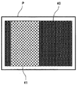
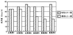
以下、具体的な実施例及び比較例により本発明を説明する。本実施例及び比較例では、第一画像形成装置としてリコーフルカラー複写機(imagio MP C5000)を、第二画像形成装置としてリコーモノクロ複写機(imagio MP 5000)を2台連結させて使用した。なお、第二画像形成装置には透明トナーを使用している。そして、下記の実施例及び比較例で示す第一定着温度及び第二定着温度で加熱定着処理を施し測定画像を出力した。測定画像は、図2に示すように、用紙Pに、第一画像形成装置1でシアントナー画像面積率100%の有色トナー部40を形成し、その有色トナー部40の半分の領域に、第二画像形成装置2で画像面積率100%の透明トナー像を重ねあわせた透明トナー部41を形成したものである。そして、この有色トナー部40の光沢度と透明トナー部41の光沢度を測定した。本実施例及び比較例における光沢度は、ハンディ光沢度計グロスメーターPG-3D(東京電色工業社製)を用いて、光の入射角60°の条件で測定した。その結果を図3に示す。
Hereinafter, the present invention will be described with reference to specific examples and comparative examples. In the present example and the comparative example, a Ricoh full color copying machine (imagio MP C5000) was used as the first image forming apparatus, and two Ricoh monochrome copying machines (imagio MP 5000) were connected as the second image forming apparatus. The second image forming apparatus uses transparent toner. Then, a heat fixing process was performed at the first fixing temperature and the second fixing temperature shown in the following examples and comparative examples, and measurement images were output. As shown in FIG. 2, the measurement image is formed by forming a
[比較例1]
第一画像形成装置1で用紙Pに有色トナー部40を転写した後、定着を行なわずに、第二画像形成装置2で透明トナー部を転写した後、第二定着装置37において定着を行なった。なお、この比較例1の構成は、特許文献1に開示される画像形成装置の構成に相当するものである。
・第一定着装置26の定着は無し
・第二定着装置37の第二定着温度は155℃
[Comparative Example 1]
After the
・ No fixing of the
[比較例2]
第一画像形成装置1で用紙Pに有色トナー部40を転写した後、第一定着装置26で定着を行い、第二画像形成装置2で透明トナー部を転写した後、第二定着装置37において定着を行なった。なお、この比較例2の構成は、特許文献2に開示される画像形成装置の構成に相当するものである。
・第一定着装置26の第一定着温度は155℃
・第二定着装置37の第二定着温度は155℃
[Comparative Example 2]
After the
The first fixing temperature of the
The second fixing temperature of the
[比較例3]
第一画像形成装置1で用紙Pに有色トナー部40を転写した後、第一定着装置26で定着を行い、第二画像形成装置2で透明トナー部を転写した後、第二定着装置37において定着を行なった。なお、この比較例3の構成は、特許文献4に開示される画像形成装置の構成に相当するものである。
・第一定着装置26の第一定着温度は155℃
・第二定着装置37の第二定着温度は170℃
[Comparative Example 3]
After the
The first fixing temperature of the
The second fixing temperature of the
[実施例1]
第一画像形成装置1で用紙Pに有色トナー部40を転写した後、第一定着装置26で定着を行い、第二画像形成装置で透明トナー部を転写した後、第二定着装置37において定着を行なった。
・第一定着装置26の第一定着温度は155℃
・第二定着装置37の第二定着温度は150℃
[Example 1]
After the
The first fixing temperature of the
The second fixing temperature of the
[実施例2]
第一画像形成装置1で用紙Pに有色トナー部40を転写した後、第一定着装置26で定着を行い、第二画像形成装置2で透明トナー部を転写した後、第二定着装置37において定着を行なった。
・第一定着装置26の第一定着温度は155℃
・第二定着装置37の第二定着温度は140℃
[Example 2]
After the
The first fixing temperature of the
The second fixing temperature of the
[実施例3]
第一画像形成装置1で用紙Pに有色トナー部40を転写した後、第一定着装置26で定着を行い、第二画像形成装置2で透明トナー部を転写した後、第二定着装置37において定着を行なった。
・第一定着装置26の第一定着温度は170℃
・第二定着装置37の第二定着温度は140℃
[Example 3]
After the
The first fixing temperature of the
The second fixing temperature of the
図3の結果から、第一定着装置26における第一定着温度よりも第二定着装置37における第二定着温度が低い実施例では、同一画像内で光沢差を付与できることがわかる。そして、第一定着温度と第二定着温度との温度差が大きいほど、有色トナー部と透明トナー部との光沢差が大きくなることがわかる。
From the results of FIG. 3, it can be seen that in the example in which the second fixing temperature in the
以上、本実施形態に係る画像形成システムにおいては、第一定着装置26で高い第一定着温度で定着された有色トナー像は光沢度が高く、第二定着装置37で低い第二定着温度で定着された透明トナー像は光沢度が低いものとなり、同一画像内で光沢差が付与されることになる。
また、本実施形態に係る画像形成システムによれば、第一定着装置26よりも用紙搬送方向下流側で、且つ第二定着装置37よりも用紙搬送方向上流側に、用紙Pの温度を検出する温度検出手段を備えている。第二定着装置37は、この温度検出手段からの検出結果を基に定着温度を制御することができる。これにより、第二定着装置37では、第一定着装置26で用紙Pに与えられた熱を第二定着装置37における定着工程に利用でき、より少ない熱量での定着が可能となる。
As described above, in the image forming system according to the present embodiment, the colored toner image fixed at the
Further, according to the image forming system according to the present embodiment, the temperature of the paper P is detected downstream of the
また、本実施形態に係る画像形成システムにおいては、第二画像形成装置2のプロセスユニット30は、透明トナー像の作像時に排出される透明トナーを再利用するためのトナー再利用機構を備えている。第二画像形成装置2のプロセスユニット30では、トナーを再利用しても紙粉等による異常画像が発生せず、低コストと高品質を両立できる。
Further, in the image forming system according to the present embodiment, the
また、本実施形態に係る画像形成システムにおいては、両面印刷の場合であっても、透明トナー像作像後は、高い温度で定着をさせないことにより、表裏のどちらの面の画像も透明トナーにより光沢差を付与することができる。 Further, in the image forming system according to the present embodiment, even in the case of double-sided printing, after the transparent toner image is formed, the image on either side of the front and back surfaces is made of transparent toner by not fixing at a high temperature. A gloss difference can be imparted.
1:第一画像形成装置
2:第二画像形成装置
10:プロセスユニット
20:中間転写ユニット
26:第一定着装置
27:第一紙搬送路
30:プロセスユニット
37:第二定着装置
38:第二紙搬送路
1: First image forming device 2: Second image forming device 10: Process unit 20: Intermediate transfer unit 26: First fixing device 27: First paper transport path 30: Process unit 37: Second fixing device 38: First Two paper transport path
Claims (4)
第一画像形成装置によって出力された記録媒体に連続して透明トナー像を作像する第二作像手段、及び記録媒体上の有色トナー像及び透明トナー像を加熱定着する第二定着手段を有する第二画像形成装置とを備え、
該第一画像形成装置に対して該第二画像形成装置がオプション搭載される画像形成システムにおいて、
第一定着手段における定着温度よりも第二定着手段における定着温度が低いことを特徴とする画像形成システム。 A first image forming apparatus having an image forming unit that forms a colored toner image on a recording medium, and a first fixing unit that heat-fixes the colored toner image on the recording medium;
A second image forming unit configured to continuously form a transparent toner image on the recording medium output by the first image forming apparatus; and a second fixing unit configured to heat and fix the colored toner image and the transparent toner image on the recording medium. A second image forming apparatus,
In the image forming system in which the second image forming apparatus is optionally mounted on the first image forming apparatus,
An image forming system, wherein a fixing temperature in the second fixing unit is lower than a fixing temperature in the first fixing unit.
上記第一定着手段よりも記録媒体移動方向下流側で、且つ上記第二定着手段よりも記録媒体移動方向上流側で、上記記録媒体の温度を検出する記録媒体温度検出手段を備え、
該第二定着手段は、該記録媒体温度検出手段からの検出結果に基づき、定着温度を制御することを特徴とする画像形成システム。 The image forming system according to claim 1.
A recording medium temperature detecting means for detecting the temperature of the recording medium downstream of the first fixing means in the recording medium moving direction and upstream of the second fixing means in the recording medium moving direction;
The image forming system, wherein the second fixing unit controls a fixing temperature based on a detection result from the recording medium temperature detecting unit.
上記第二作像手段は、作像時に排出されるトナーを再利用するためのトナー再利用機構を備えることを特徴とする画像形成システム。 The image forming system according to claim 1 or 2,
The image forming system, wherein the second image forming unit includes a toner reuse mechanism for reusing toner discharged at the time of image formation.
上記記録媒体の両面に画像形成を行う場合には、上記第一画像形成装置で該記録媒体の両面に有色トナー像を転写定着した後に、上記第二画像形成装置で該記録媒体の両面に透明トナー像を転写定着させることを特徴とする画像形成システム。 The image forming system according to claim 1, 2 or 3.
When image formation is performed on both sides of the recording medium, a colored toner image is transferred and fixed on both sides of the recording medium by the first image forming apparatus, and then transparent on both sides of the recording medium by the second image forming apparatus. An image forming system for transferring and fixing a toner image.
Priority Applications (1)
| Application Number | Priority Date | Filing Date | Title |
|---|---|---|---|
| JP2010063239A JP2011197319A (en) | 2010-03-18 | 2010-03-18 | Image forming system |
Applications Claiming Priority (1)
| Application Number | Priority Date | Filing Date | Title |
|---|---|---|---|
| JP2010063239A JP2011197319A (en) | 2010-03-18 | 2010-03-18 | Image forming system |
Publications (1)
| Publication Number | Publication Date |
|---|---|
| JP2011197319A true JP2011197319A (en) | 2011-10-06 |
Family
ID=44875629
Family Applications (1)
| Application Number | Title | Priority Date | Filing Date |
|---|---|---|---|
| JP2010063239A Withdrawn JP2011197319A (en) | 2010-03-18 | 2010-03-18 | Image forming system |
Country Status (1)
| Country | Link |
|---|---|
| JP (1) | JP2011197319A (en) |
Cited By (7)
| Publication number | Priority date | Publication date | Assignee | Title |
|---|---|---|---|---|
| JP2013117711A (en) * | 2011-10-31 | 2013-06-13 | Ricoh Co Ltd | Recording medium processing method, image forming method, recording medium processing apparatus, and image forming system |
| JP2013120222A (en) * | 2011-12-06 | 2013-06-17 | Konica Minolta Business Technologies Inc | Image forming device |
| US9020382B2 (en) | 2011-12-13 | 2015-04-28 | Ricoh Company, Ltd. | Image forming apparatus |
| CN109709783A (en) * | 2017-10-26 | 2019-05-03 | 东芝泰格有限公司 | image forming system |
| CN111458996A (en) * | 2019-01-18 | 2020-07-28 | 富士施乐株式会社 | Image forming apparatus and foil printing image forming apparatus |
| JP2021162838A (en) * | 2020-03-31 | 2021-10-11 | 株式会社リコー | Image forming device |
| US11448995B2 (en) | 2019-04-19 | 2022-09-20 | Hewlett-Packard Development Company, L.P. | Clear toner based photo-finishing apparatus to realize uniform glossiness of printed image |
-
2010
- 2010-03-18 JP JP2010063239A patent/JP2011197319A/en not_active Withdrawn
Cited By (13)
| Publication number | Priority date | Publication date | Assignee | Title |
|---|---|---|---|---|
| JP2013117711A (en) * | 2011-10-31 | 2013-06-13 | Ricoh Co Ltd | Recording medium processing method, image forming method, recording medium processing apparatus, and image forming system |
| JP2013120222A (en) * | 2011-12-06 | 2013-06-17 | Konica Minolta Business Technologies Inc | Image forming device |
| USRE47726E1 (en) | 2011-12-13 | 2019-11-12 | Ricoh Company, Ltd. | Image forming apparatus |
| US9020382B2 (en) | 2011-12-13 | 2015-04-28 | Ricoh Company, Ltd. | Image forming apparatus |
| CN109709783B (en) * | 2017-10-26 | 2022-05-24 | 东芝泰格有限公司 | Image forming system |
| JP2019078942A (en) * | 2017-10-26 | 2019-05-23 | 株式会社東芝 | Image forming system |
| CN109709783A (en) * | 2017-10-26 | 2019-05-03 | 东芝泰格有限公司 | image forming system |
| CN111458996A (en) * | 2019-01-18 | 2020-07-28 | 富士施乐株式会社 | Image forming apparatus and foil printing image forming apparatus |
| JP2020118733A (en) * | 2019-01-18 | 2020-08-06 | 富士ゼロックス株式会社 | Image forming apparatus and foil image forming apparatus |
| JP7255195B2 (en) | 2019-01-18 | 2023-04-11 | 富士フイルムビジネスイノベーション株式会社 | Image forming apparatus and foil image forming apparatus |
| CN111458996B (en) * | 2019-01-18 | 2024-05-14 | 富士胶片商业创新有限公司 | Image forming apparatus and foil printing image forming apparatus |
| US11448995B2 (en) | 2019-04-19 | 2022-09-20 | Hewlett-Packard Development Company, L.P. | Clear toner based photo-finishing apparatus to realize uniform glossiness of printed image |
| JP2021162838A (en) * | 2020-03-31 | 2021-10-11 | 株式会社リコー | Image forming device |
Similar Documents
| Publication | Publication Date | Title |
|---|---|---|
| US8655252B2 (en) | Image control device | |
| JP2010114498A (en) | Image forming apparatus and image reading apparatus | |
| JP2011197319A (en) | Image forming system | |
| JP6459257B2 (en) | Image forming apparatus | |
| JP2009175548A (en) | Image projection device | |
| JP5975287B2 (en) | Image forming apparatus, image forming system, and image processing program | |
| JP2005315966A (en) | Image forming apparatus | |
| KR20060065547A (en) | Image forming apparatus | |
| JP2010204494A (en) | Exposure apparatus and image forming apparatus | |
| JP2011100035A (en) | Image forming apparatus | |
| JP6349893B2 (en) | Image forming apparatus | |
| JP2012098654A (en) | Multiple image forming apparatus | |
| JP2011197321A (en) | Image forming system | |
| JP2016099589A (en) | Image forming apparatus | |
| JP2020071236A (en) | Image forming apparatus | |
| JP2012189918A (en) | Image forming apparatus | |
| US10324403B2 (en) | Image forming apparatus containing fixing member, blowing section, and hardware processor | |
| JPH0466970A (en) | Color printer | |
| JP2015060030A (en) | Image forming apparatus | |
| JP6573169B2 (en) | Image forming apparatus | |
| JP2016212302A (en) | Image formation apparatus | |
| JP6237184B2 (en) | Fixing apparatus and image forming apparatus | |
| JP2020020956A (en) | Image forming apparatus and image forming method | |
| JP2010230971A (en) | Image forming apparatus | |
| JP2007156173A (en) | Image forming apparatus |
Legal Events
| Date | Code | Title | Description |
|---|---|---|---|
| A300 | Withdrawal of application because of no request for examination |
Free format text: JAPANESE INTERMEDIATE CODE: A300 Effective date: 20130604 |