JP2011193159A - Monitoring system, image processor, and monitoring method - Google Patents
Monitoring system, image processor, and monitoring method Download PDFInfo
- Publication number
- JP2011193159A JP2011193159A JP2010056637A JP2010056637A JP2011193159A JP 2011193159 A JP2011193159 A JP 2011193159A JP 2010056637 A JP2010056637 A JP 2010056637A JP 2010056637 A JP2010056637 A JP 2010056637A JP 2011193159 A JP2011193159 A JP 2011193159A
- Authority
- JP
- Japan
- Prior art keywords
- video signal
- monitoring
- area
- image
- image processing
- Prior art date
- Legal status (The legal status is an assumption and is not a legal conclusion. Google has not performed a legal analysis and makes no representation as to the accuracy of the status listed.)
- Pending
Links
Images


Landscapes
- Closed-Circuit Television Systems (AREA)
- Alarm Systems (AREA)
- Image Processing (AREA)
Abstract
Description
本発明は、撮像装置によって撮像された画像を利用する監視システム、画像処理装置、及び監視方法に関する。 The present invention relates to a monitoring system, an image processing apparatus, and a monitoring method that use an image captured by an imaging apparatus.
近年、ビル、駅、空港等の建物内や街中等の監視のために、撮像装置を用いた監視システムが導入されている。既設の監視システムでは、撮像装置からは遠隔に設置された監視センタなどでの映像の集中管理が行われている。監視センタ内では、撮像装置が取得した映像の記憶媒体への記憶や監視員による目視等が行われている。 In recent years, a monitoring system using an imaging device has been introduced for monitoring inside buildings such as buildings, stations, and airports, and in towns. In an existing monitoring system, centralized video management is performed at a monitoring center installed remotely from an imaging device. In the monitoring center, the video acquired by the imaging device is stored in a storage medium or visually observed by a monitor.
既設の監視システムでは、安価で低機能な撮像装置を使用していることが多い。一般的に安価な撮像装置は、ズームやパンができず、撮像画角が固定されている。特に監視用途の撮像装置の画角は広範囲に調整されている。このような場合、監視対象が小さく撮像されてしまい、当該画像を保存したり監視員が目視したりする際に、画像内に生じている事象が判断できずに見逃してしまいかねない。このため、低機能の監視用撮像装置で撮像された画像を高解像度化して、監視に役立てることが望まれる。 Existing monitoring systems often use inexpensive and low-function imaging devices. Generally, an inexpensive imaging device cannot perform zooming and panning, and has a fixed imaging angle of view. In particular, the angle of view of an imaging apparatus for monitoring is adjusted over a wide range. In such a case, the monitoring target is captured in a small size, and when the image is stored or viewed by a monitoring person, an event occurring in the image cannot be determined and may be overlooked. For this reason, it is desired to increase the resolution of an image captured by a low-function monitoring imaging device and to use it for monitoring.
例えば特許文献1には、低解像度映像に高周波成分を復元させて超解像度の映像の復元及び再構成を行なう映像復元及び再構成方法が開示されている。また、特許文献2には、各時刻の座標を全体の運動によって拘束して、大きなずれのない位置合せを行ない、重ね合わせた画像に対して高解像度化処理を行う画像処理装置及び画像処理方法が開示されている。
For example,
しかしながら、特許文献1に記載の技術では、既に貯蔵された画像に対して高解像度化を行なうため、撮像画像をリアルタイムで高解像度化して監視員による監視に提供するシステムには適用できない。また、特許文献2に記載の技術では、予め運動を拘束しておく必要があり、所定区域内で人物の動きを監視する監視システムへの適用は困難である。
However, since the technique described in
本発明は、前記のような問題に鑑みなされたもので、監視対象体を含む映像信号を容易に高解像度化して受像装置に提供することが可能になる監視システム、画像処理装置、及び監視方法を提供することを目的とする。 SUMMARY OF THE INVENTION The present invention has been made in view of the above-described problems. A monitoring system, an image processing apparatus, and a monitoring method capable of easily providing a video signal including a monitoring target with high resolution and providing it to an image receiving apparatus. The purpose is to provide.
本発明の一実施形態に係る監視システムは、監視対象体を撮影して第1の映像信号を得る撮像装置と、前記撮像装置に接続される画像処理装置であって、前記第1の映像信号から、前記監視対象体を含むエリアを検出するエリア検出手段と、前記エリア検出部が検出したエリアの映像信号を高解像度化処理して第2の映像信号を生成する高解像度化処理手段とを具備する画像処理装置と、前記画像処理装置に接続され、前記第2の映像信号を表示又は収録する受像装置とを具備する。 A monitoring system according to an embodiment of the present invention includes an imaging device that captures a monitoring target and obtains a first video signal, and an image processing device connected to the imaging device, wherein the first video signal From the above, area detection means for detecting an area including the monitoring object, and high resolution processing means for generating a second video signal by performing high resolution processing on the video signal of the area detected by the area detection unit. And an image receiving device connected to the image processing device and displaying or recording the second video signal.
本発明の一実施形態に係る画像処理装置は、監視対象体を撮影して第1の映像信号を得る撮像装置と、前記撮像装置に接続され、前記第1の映像信号に画像処理を施して第2の映像信号を生成する画像処理装置と、前記画像処理装置に接続され、前記第2の映像信号を表示又は収録する受像装置とを具備する監視システムにおいて用いられる画像処理装置であって、前記第1の映像信号から、前記監視対象体を含むエリアを検出するエリア検出手段と、前記エリア検出部が検出したエリアの映像信号を高解像度化処理して前記第2の映像信号を生成する高解像度化処理手段とを具備する。 An image processing apparatus according to an embodiment of the present invention includes an imaging apparatus that captures a monitoring target and obtains a first video signal, and is connected to the imaging apparatus, and performs image processing on the first video signal. An image processing apparatus used in a monitoring system comprising: an image processing apparatus that generates a second video signal; and an image receiving apparatus that is connected to the image processing apparatus and displays or records the second video signal, An area detection unit for detecting an area including the monitoring target object from the first video signal, and generating a second video signal by performing high resolution processing on the video signal of the area detected by the area detection unit. High resolution processing means.
本発明の一実施形態に係る監視方法は、撮像装置によって監視対象体を撮影して第1の映像信号を得るステップと、前記撮像装置に接続される画像処理装置によって、前記第1の映像信号から、前記監視対象体を含むエリアを検出するステップと、前記検出したエリアの映像信号を高解像度化処理して第2の映像信号を生成するステップと、前記画像処理装置に接続される前記第2の映像信号を表示又は収録するステップとを備える。 The monitoring method according to an embodiment of the present invention includes a step of obtaining a first video signal by photographing a monitoring object with an imaging device, and an image processing device connected to the imaging device. Detecting an area including the object to be monitored, generating a second video signal by increasing the resolution of the video signal of the detected area, and the first connected to the image processing device Displaying or recording two video signals.
本発明の一実施形態に係る監視システム、画像処理装置、及び監視方法によれば、監視対象体を含む映像信号を容易に高解像度化して受像装置に提供することが可能になる。 According to a monitoring system, an image processing apparatus, and a monitoring method according to an embodiment of the present invention, it is possible to easily increase the resolution of a video signal including a monitoring target and provide it to an image receiving apparatus.
以下、図面を参照して本発明による監視システムの実施形態を説明する。 Embodiments of a monitoring system according to the present invention will be described below with reference to the drawings.
図1は、本発明の一実施形態に係る監視システムの構成の概略を示すブロック図である。図1に示すように、この監視システムは撮像装置10、画像処理装置20、及び受像装置30を具備する。
FIG. 1 is a block diagram showing an outline of a configuration of a monitoring system according to an embodiment of the present invention. As illustrated in FIG. 1, the monitoring system includes an
撮像装置10は、監視対象となる建物、工場、電力プラント、街頭等に設置される。撮像装置10は例えばビデオカメラ等を具備し、動画像を撮像する機能を有する。撮像装置10は、映像信号(動画像信号)Iを出力する。
The
映像信号Iでは、所定画素数の複数のフレームが連続しており、この複数フレームの連続によって動画像が構成される。映像信号Iは、有線又は無線のネットワークを介して画像処理装置20に送られる。
In the video signal I, a plurality of frames having a predetermined number of pixels are continuous, and a moving image is formed by the continuation of the plurality of frames. The video signal I is sent to the
画像処理装置20は、高解像度化処理部24を具備しており、映像信号Iから切り出した所定エリアの映像信号に対して高解像度化処理を行う。高解像度化された映像信号Oは、画像処理装置20に接続されている受像装置30に送られる。
The
受像装置30は、撮像装置10からは遠隔に設けられた監視センタに設置される。受像装置30は例えば液晶ディスプレイ(LCD)等の表示装置を具備し、画像処理装置20から受信した映像信号Oは、この表示装置によって表示される。監視センタにいる監視者はこの表示装置を参照して監視対象を監視する。また受像装置30は、監視者の操作に応じて画像処理装置20に操作信号を供給するための、例えばキーボードやマウス等の操作入力部を具備する。受像装置30の機能は、例えばパーソナルコンピュータ(PC)等の通常のコンピュータ装置によって実現されてもよい。
The
一般の監視システムでは、撮像装置10から出力される映像信号Iがそのまま受像装置30に送られて、監視用途に用いられる。従って、映像信号Iの映像サイズは、受像装置30における表示サイズに合わせて設定される。一方、本実施形態に係る監視システムでは、撮像装置10と受像装置30の間に画像処理装置20が接続される。画像処理装置20は、映像信号Iから切り出した所定エリアの映像信号に対して高解像度化処理を行い、処理後の映像信号Oを受像装置30に出力する。撮像装置10と受像装置30は既存の構成のままであるため、映像信号Iの映像サイズと同様に、映像信号Oの映像サイズも受像装置30の表示サイズに合わせて設定される。
In a general monitoring system, the video signal I output from the
図2は、図1に示す画像処理装置20の詳細な機能構成を示すブロック図である。画像処理装置20は図示しないプロセッサ、プログラムメモリ、及びワークメモリを具備し、プロセッサがプログラムメモリに記憶された所定のプログラムを読み出して実行することで、種々の機能を実現してもよい。あるいは、画像処理装置20の機能は、ロジック回路によってハードウェア的に実現されてもよく、ハードウェアとソフトウェアの協働によって実現されてもよい。
FIG. 2 is a block diagram showing a detailed functional configuration of the
画像処理装置20は、映像入力処理部21、エリア設定部22、スイッチ23、高解像度化処理部24、事象検出部25、画像保存処理部26、及びメモリ27を具備する。
The
映像入力処理部21は、撮像装置10から送られる映像信号Iに対して、フォーマット変換等の所要の処理を施し、画像処理装置20において映像信号Iを取り扱えるようにする。画像処理装置20にアナログの映像信号Iが入力する場合に、映像入力処理部21が備えるA/D(アナログデジタル)変換部によって、映像信号Iをデジタル変換するように構成されてもよい。
The video
エリア設定部22は、映像信号Iから切り出すエリアを決定する。エリア設定部22は、映像信号I内のフレーム間の差に基づいて、映像信号Iから物体又は背景との差異を検出する。検出された物体、又は背景との差異を含むエリアが、切り出しエリアとして抽出される。エリア設定部22が抽出したエリアの情報は、スイッチ23を介して高解像度化処理部23に送られる。
The
スイッチ23は、高解像度化処理部23へ入力する信号を、エリア設定部22からの信号と受像装置30から送られる操作信号との間で切換える。スイッチ23の切換えは、監視員の指示に基づいて受像装置30から送られる操作信号によって行なわれる。スイッチ23が、受像装置30から送られる操作信号を高解像度化処理部23へ伝達する場合、当該操作信号には、監視者が受像装置の操作入力部によって指定した映像内のエリアの情報が含まれる。
The
高解像度化処理部23は、スイッチ23を介して入力された情報に基づいて、指定されたエリアを映像信号Iから切り出し、当該切り出したエリアの映像信号に対して高解像度化処理を施す。高解像度化処理された映像信号は、例えば映像信号Iと同じ映像サイズの映像信号Oとして、受像装置30に出力される。あるいは、受像装置30の表示能力に応じて、更に高解像度の画像が出力されてもよい。高解像度化処理は、1フレームの映像信号に基づいて、又は複数フレーム間の相関情報に基づいて行うことができる。高解像度化処理部23は、複数の高解像度化方法を実行可能であってもよく、入力する映像信号Iの種類に応じて、あるいは受像装置30から送られる操作信号に基づいて、使用する高解像度化方法が選択されてもよい。また、複数の高解像度化方法が組み合わせて用いられてもよい。
Based on the information input via the
高解像度化処理によって、撮像装置10から入力される映像信号Iの解像度不足、画素不足が補われ、高解像の映像が得られる。
The resolution enhancement process compensates for the lack of resolution and pixel shortage of the video signal I input from the
事象検出部25は、映像信号Oから被写体の危険動作等、特定の事象(行動)を示す情報を検出する。例えば事象検出部25は、侵入の検知やはみ出し、あるいは被写体の手の動き等を検出する。
The
従って、映像信号Oの解像度が映像信号Iの2倍となっていれば、2倍の検出精度で事象を検知することができる。すなわち、侵入検知やはみ出し検知の精度が2倍に向上する。また、映像信号Iにおいては遠くに映っている(すなわち小さく映っている)事象を検知及び判定する精度が向上する。 Therefore, if the resolution of the video signal O is twice that of the video signal I, the event can be detected with double detection accuracy. That is, the accuracy of intrusion detection and protrusion detection is doubled. In addition, the accuracy of detecting and determining an event that is far away (that is, smaller) in the video signal I is improved.
事象検出部25が特定の事象を検出したら、事象検出部25から画像保存処理部26に検知信号が送られる。画像保存処理部26は、検知信号に応じて、当該特定の事象が含まれるフレームをメモリ27に保存する。また検知信号は、受像装置30にも出力される。受像装置30では、この検知信号に応じてアラーム表示等が行われてもよい。
When the
メモリ27は、例えばハードディスク装置HDDやフラッシュメモリ等の記憶装置を含む。メモリ27には、事象検出部25によって検出された危険動作等を示す高解像度化された映像信号が記憶されるため、後から、このような映像信号を参照することができる。
The
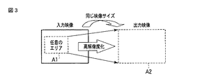
図3は、画像処理装置の高解像度化処理部によって、映像信号Iから切り出されたエリアが高解像度化されて、映像信号Oとして生成される様子を模式的に表した図である。 FIG. 3 is a diagram schematically illustrating a state in which an area cut out from the video signal I is increased in resolution and generated as the video signal O by the resolution increasing processing unit of the image processing apparatus.
図3に示すように、高解像度化処理部24は、エリア設定部22又は操作信号によって指定されるエリアA1を映像信号Iから切り出す。切り出されたエリアA1の映像信号には、高解像度化処理が行われ、エリアA2を有する映像信号Oが生成される。このエリアA2の映像サイズは、映像信号Iの映像サイズと等しくなる。
As shown in FIG. 3, the resolution
このエリアA2からなる映像信号Oが受像装置30に送られて、表示装置に表示される。監視者はこの映像信号Oに基づく表示を参照して監視対象を監視する。
The video signal O comprising this area A2 is sent to the
このように、本実施形態に係る監視システムによれば、映像信号I中の所定のエリアの画像を高解像度化して、受像装置30によって表示することができる。従って、高精度での監視が可能となる。
As described above, according to the monitoring system of the present embodiment, the image of the predetermined area in the video signal I can be increased in resolution and displayed by the
図4は、上述の監視システムにおいて、取得された映像信号から移動物体を含むエリアを抽出する場合の一例を示す図である。 FIG. 4 is a diagram illustrating an example of extracting an area including a moving object from an acquired video signal in the above-described monitoring system.
図4に示す例では、時刻t=0での映像信号Iに基づく入力映像からは、エリアA3において人物が検出される。この人物が移動中である場合、続く時刻t=1での入力映像からは、エリアA3とは少しずれたエリアA4において当該人物が検出される。更に、次の時刻t=2での入力映像からは、エリアA5において当該人物が検出される。 In the example shown in FIG. 4, a person is detected in the area A3 from the input video based on the video signal I at time t = 0. When the person is moving, the person is detected in the area A4 slightly deviated from the area A3 from the subsequent input video at time t = 1. Further, the person is detected in the area A5 from the input video at the next time t = 2.
このような移動体の検出は、エリア設定部22が、各フレームから自動的に物体を検出することで実現できる。
Such detection of a moving body can be realized by the
高解像度化処理部23は、t=0での入力映像についてはエリアA3を切り出して高解像度化処理を行う。また、t=1での入力映像についてはエリアA4が、t=2での入力映像についてはエリアA5が切り出されて高解像度化処理が行われる。従って、受像装置30では移動体を追随して高解像度で表示でき、監視員は移動体を注意して監視することができるようになる。
The high
なお、図4では移動する人物を一例として示したが、人物に限らず、動物や車両等、他の移動体も同様に検出することができる。 In addition, although the person who moves is shown as an example in FIG. 4, not only a person but other moving bodies, such as an animal and a vehicle, can be detected similarly.
図5は、上述の監視システムにおいて、取得された映像信号から背景との相違を含むエリアを抽出する場合の一例を示す図である。 FIG. 5 is a diagram illustrating an example of extracting an area including a difference from the background from the acquired video signal in the above-described monitoring system.
図5に示す例では、時刻t=0での映像信号Iに基づく入力映像には、背景映像のみが含まれている。その後、監視対象領域に何らかの物体が置かれる等すると、続く時刻t=1での入力映像からは、当該物体を含むエリアA6がエリア設定部22によって検出される。
In the example shown in FIG. 5, the input video based on the video signal I at time t = 0 includes only the background video. Thereafter, when any object is placed in the monitoring target area, the
高解像度化処理部24は、このt=1での入力映像からエリアA6を切り出して高解像度化処理を行う。従って、受像装置30では、物体の出現を高解像度化された映像信号から表示することができ、監視員は監視対象における突然の変化を、容易に知ることができる。
The high
背景映像は、エリア設定部22あるいは映像入力処理部21によって予め保持されていてもよい。例えば所定数以上のフレームに渡って映像信号に変化が無い場合、あるいは微小な変化のみが生じている場合は、これらのフレームは背景映像を示していると判定できる。
The background video may be held in advance by the
このような物体の出現を高解像度画像で確認できるため、監視員は例えば危険物等の物体の置き去りを容易に確認することができる。 Since the appearance of such an object can be confirmed with a high-resolution image, the monitor can easily confirm the leaving of an object such as a dangerous object.
また、映像から突然物体が消失する場合も、同様に検出することができる。一定時間以上(一定数以上のフレームにわたって)変化の無い映像から何らかの物体が消失すれば、エリア設定部22は、上記と同様に、当該物体の消失部分を含むエリア検出することができる。高解像度化処理部24は、当該エリアを切り出して高解像度化処理を行うため、受像装置30では、物体の消失を高解像度化された映像信号から表示することができ、監視員は監視対象における突然の変化を、容易に知ることができる。
Further, when an object suddenly disappears from the video, it can be detected in the same manner. If a certain object disappears from a video that has not changed for a certain period of time (over a certain number of frames or more), the
このような物体の消失を高解像度画像で確認できるため、監視員は例えば展示物の置き引き等を容易に確認することができる。 Since the disappearance of such an object can be confirmed with a high-resolution image, the monitoring person can easily confirm, for example, the placement of the exhibits.
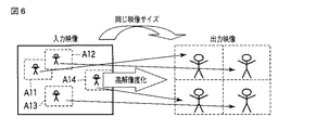
図6は、上述の監視システムにおいて、取得された映像信号に複数の検出対象体が含まれる場合の表示の一例を示す図である。 FIG. 6 is a diagram illustrating an example of display when a plurality of detection objects are included in the acquired video signal in the above-described monitoring system.
図6に示す例では、映像信号Iに基づく入力映像に、4つの検出対象体(4人の人物)が含まれており、それぞれを内包するエリアA11〜A14がエリア設定部22によって検出されている。
In the example shown in FIG. 6, four detection objects (four persons) are included in the input video based on the video signal I, and areas A11 to A14 including each of them are detected by the
高解像度化処理部23は、これらのエリアA11〜A14をそれぞれ切り出し、高解像度化処理を施す。このとき、高解像度化処理された映像信号は、映像信号Iと同じ映像サイズの映像信号Oとして、受像装置30に出力される。このとき映像信号Oは、4つのエリアがマルチ画面表示されるように生成される。すなわち、映像信号Oに基づく出力映像は表示画面上で4分割されて、それぞれの分割画面上にエリアA11〜A14を高解像度化した映像が割り当てられる。また、受像装置30の表示能力を向上させることができるような場合は、エリアA11〜A14のそれぞれを、映像信号Iと同じ映像サイズあるいはそれ以上にまで高解像化して表示画面上に並べるようにしてもよい。例えば受像装置30の表示サイズが映像信号Iの映像サイズの4倍あれば、エリアA11〜A14のそれぞれを、映像信号Iと同じ映像サイズにまで高解像化して表示画面上に並べて面積比4倍で表示するように構成することもできる。
The high
なお図6の例では、4つの検出対象体が検出され、表示画面が4分割される例を示したが、検出される対象体の数に応じて画面の分割方法が変更されてもよい。 In the example of FIG. 6, four detection objects are detected, and the display screen is divided into four. However, the screen division method may be changed according to the number of detected objects.
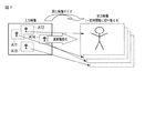
図7は、上述の監視システムにおいて、取得された映像信号に複数の検出対象体が含まれる場合の表示の他の一例を示す図である。 FIG. 7 is a diagram illustrating another example of display when a plurality of detection objects are included in the acquired video signal in the monitoring system described above.
図7に示す例でも、図6と同様に、映像信号Iに基づく入力映像に、4つの検出対象体(4人の人物)が含まれており、それぞれを内包するエリアA11〜A14がエリア設定部22によって検出されている。
Also in the example shown in FIG. 7, as in FIG. 6, the input video based on the video signal I includes four detection objects (four persons), and the areas A <b> 11 to A <b> 14 that contain each of them are area settings. It is detected by the
高解像度化処理部23は、これらのエリアA11〜A14をそれぞれ切り出し、高解像度化処理を施す。このとき、高解像度化処理された映像信号は、映像信号Iと同じ映像サイズの映像信号Oとして、受像装置30に出力される。
The high
このとき映像信号Oは、4つのエリア時間分割されて画面表示されるように生成される。すなわち、4つのエリアA11〜A14はそれぞれ、映像信号Iと同じ映像サイズに高解像度化され、表示画面上では、所定の時間間隔で順次切換えられて表示される。 At this time, the video signal O is generated so as to be displayed on the screen after being divided into four area times. That is, each of the four areas A11 to A14 is increased in resolution to the same video size as the video signal I, and is sequentially switched and displayed on the display screen at predetermined time intervals.
なお図7の例では、4つの検出対象体が検出され、表示画面が4分割される例を示したが、検出される対象体の数に応じて表示の時間間隔が変更されてもよい。 In the example of FIG. 7, four detection objects are detected and the display screen is divided into four. However, the display time interval may be changed according to the number of detected objects.
続いて、本実施形態に係る監視システムに用いられる画像処理装置の動作について説明する。 Subsequently, the operation of the image processing apparatus used in the monitoring system according to the present embodiment will be described.
図8は、上述の画像処理装置によって実行される動作の一例を示すフローチャートである。 FIG. 8 is a flowchart illustrating an example of an operation executed by the above-described image processing apparatus.
図8に示すように、まず受像装置10から映像入力処理部21に映像信号Iが入力する(ステップS81)。映像処理部21は入力する映像信号Iに所定の処理を施し、エリア設定部22及び高解像度化処理部24に転送する。
As shown in FIG. 8, first, the video signal I is input from the
エリア設定部22は、映像信号Iから切り出されるエリアを決定する(ステップS82)。あるいは、監視者が受像装置30を介して指示するエリアが切り出されるエリアとして決定される(ステップS82)。スイッチ23の設定に応じて、エリア設定部22によって決定されたエリア情報と受像装置30から送られるエリア情報のいずれかが、高解像度化処理部24に送られる。
The
高解像度処理部24は、映像入力処理部21から送られた映像信号Iから、スイッチ23から送られたエリア情報に対応する部分を切り出し、当該切り出された部分に、高解像度化処理を施す(ステップS83)。高解像度化によって映像信号Iと同じ映像サイズで生成された映像信号Oが、高解像度化処理部24から出力される。
The high
事象検出部25によって映像信号Oから特定の事象が検出されたら、当該事象を含む映像フレームが映像信号Oから抽出されてメモリ27に保存される(ステップS84)。検出事象を含むフレームだけに限らず、前後の映像フレームも共にメモリ27に保存されてもよい。
When a specific event is detected from the video signal O by the
高解像度化処理部24から出力される映像信号Oは、受像装置30に出力され(ステップS85)、監視者による目視、あるいは受像装置30における録画に供される。
The video signal O output from the high
以上述べたように、本実施形態に係る監視システムでは、撮像装置と受像装置の間に、画像処理装置が接続される。撮像装置と受像装置は、既設の装置であってもよい。 As described above, in the monitoring system according to the present embodiment, the image processing device is connected between the imaging device and the image receiving device. The imaging device and the image receiving device may be existing devices.
画像処理装置は、撮像装置が撮像した映像信号から、移動体や背景画像のとの変化などの検出対象体を検出する。検出された検出対象体を含むエリア、又は監視者の指示によって選択されたエリアは高解像度化処理され、入力する映像信号と同じ映像サイズの映像信号として受像装置に出力される。 The image processing apparatus detects a detection target body such as a change from a moving body or a background image from a video signal captured by the imaging apparatus. The area including the detected object to be detected or the area selected by the supervisor's instruction is subjected to high resolution processing and output to the image receiving apparatus as a video signal having the same video size as the input video signal.
このため受像装置側では、検出された移動体や背景画像との変化等、又は監視者が選択したエリアを、高解像度で取得することができ、監視の精度を向上させることができる。 For this reason, on the image receiving device side, the change from the detected moving body and the background image, or the area selected by the monitor can be acquired with high resolution, and the monitoring accuracy can be improved.
フレーム毎に移動体が検出されるため、移動体の移動を画像処理装置が自動的に追随することができる。従って受像装置では、高解像度化された移動体の移動映像を容易に取得することができる。また、背景画像との変化が検出されて高解像度化されるので、小さい物体の置き引きや、小さな危険物の置き去りといった事象も容易に確認することができるようになる。 Since the moving body is detected for each frame, the image processing apparatus can automatically follow the movement of the moving body. Therefore, the image receiving apparatus can easily acquire the moving image of the moving body with high resolution. In addition, since a change from the background image is detected and the resolution is increased, it is possible to easily confirm an event such as a small object being left behind or a small dangerous object being left behind.
更に、本実施形態に係る監視システムでは、高解像度化された映像信号から、特定の事象を検出する。検出された特定の事象を含むフレームは、メモリに保存される。 Furthermore, in the monitoring system according to the present embodiment, a specific event is detected from the video signal with a high resolution. The frame containing the specific event detected is stored in memory.
特定の事象としては、何らかの事件、事故、あるいは犯罪等が挙げられる。例えば万引き等の現場で、犯人の細かな手の動きを高解像度化された映像信号から高精度で検出することができる。このようにして検出されたフレームがメモリに保存されるため、事故や事件の証拠画像を高解像度で保存することができる。 Specific events include some incidents, accidents, or crimes. For example, in a shoplifting site, it is possible to detect a fine hand movement of a criminal from a high-resolution video signal with high accuracy. Since the frames detected in this way are stored in the memory, it is possible to store evidence images of accidents and incidents with high resolution.
上述の撮像装置10は、監視システム用途として一般的に用いられるカラーテレビ信号の伝送規格であるNTSC(National Television System Committee)方式の映像信号を出力する撮像装置であってもよい。
The
また、上述の実施形態では、画像処理装置20と受像装置30は別個に設けられたが、画像処理装置20が受像装置30に内蔵されるなどして、画像処理装置20と受像装置30は一体に設けられてもよい。
In the above-described embodiment, the
本実施形態に係る監視システムは、主として産業分野、社会インフラ分野でのセーフティ・セキュリティシステムに適用することができる。具体的には、産業用プラント、電力プラント、駅、空港、店舗等の用途にて不審者監視、侵入監視などの具合的なアプリケーションで長期的に運用する必要があるシステムでの適用が考えられる。 The monitoring system according to the present embodiment can be applied mainly to safety / security systems in the industrial field and social infrastructure field. Specifically, it can be applied to systems that need to be operated for a long time with specific applications such as suspicious person monitoring and intrusion monitoring in industrial plants, power plants, stations, airports, stores, etc. .
本発明は、前記各実施形態に限定されるものではなく、実施段階ではその要旨を逸脱しない範囲で種々に変形することが可能である。さらに、前記各実施形態には種々の段階の発明が含まれており、開示される複数の構成要件における適宜な組み合わせにより種々の発明が抽出され得る。例えば、1つの実施形態に示される全構成要件から幾つかの構成要件が削除されたり、幾つかの実施形態に示される構成要件が組み合わされても、発明が解決しようとする課題の欄で述べた課題が解決でき、発明の効果の欄で述べられている効果が得られる場合には、この構成要件が削除されたり組み合わされた構成が発明として抽出され得るものである。 The present invention is not limited to the above-described embodiments, and various modifications can be made without departing from the scope of the invention at the stage of implementation. Further, each of the embodiments includes inventions at various stages, and various inventions can be extracted by appropriately combining a plurality of disclosed constituent elements. For example, even if some constituent elements are deleted from all the constituent elements shown in one embodiment or the constituent elements shown in some embodiments are combined, they are described in the column of the problem to be solved by the invention. In the case where the problems described above can be solved and the effects described in the “Effects of the Invention” can be obtained, a configuration in which these constituent requirements are deleted or combined can be extracted as an invention.
10…撮像装置、20…画像処理装置、21…映像入力処理部、22…エリア設定部、23…スイッチ、24…高解像度化処理部、25…事象検出部、26…画像保存処理部、27…メモリ、30…受像装置。
DESCRIPTION OF
Claims (13)
前記撮像装置に接続される画像処理装置であって、
前記第1の映像信号から、前記監視対象体を含むエリアを検出するエリア検出手段と、
前記エリア検出部が検出したエリアの映像信号を高解像度化処理して第2の映像信号を生成する高解像度化処理手段と、
を具備する画像処理装置と、
前記画像処理装置に接続され、前記第2の映像信号を表示又は収録する受像装置と
を具備する監視システム。 An imaging device that captures a monitoring object and obtains a first video signal;
An image processing device connected to the imaging device,
Area detecting means for detecting an area including the monitoring object from the first video signal;
High resolution processing means for generating a second video signal by performing high resolution processing on the video signal of the area detected by the area detection unit;
An image processing apparatus comprising:
A monitoring system comprising: an image receiving device connected to the image processing device and displaying or recording the second video signal.
前記エリア検出手段は、前記第1の映像信号のフレーム間の差分から、前記移動体を検出する請求項1に記載の監視システム。 The monitoring object includes a moving object,
The monitoring system according to claim 1, wherein the area detection unit detects the moving body from a difference between frames of the first video signal.
前記エリア検出手段は、前記背景映像と前記第1の映像信号のフレームとの差分から、前記相違を検出する請求項1に記載の監視システム。 The monitoring object includes a difference from a background image acquired in advance,
The monitoring system according to claim 1, wherein the area detecting unit detects the difference from a difference between the background video and a frame of the first video signal.
前記高解像度化処理手段は、前記複数のエリアをそれぞれ高解像度化し、前記複数のエリアが前記受像装置の表示画面を分割して表示されるように前記第2の映像信号を生成する請求項1に記載の監視システム。 The area detecting means detects a plurality of areas including a plurality of monitoring objects from the first video signal,
2. The high resolution processing means increases the resolution of each of the plurality of areas, and generates the second video signal so that the plurality of areas are displayed by dividing a display screen of the image receiving device. The monitoring system described in.
前記高解像度化処理手段は、前記複数のエリアをそれぞれ高解像度化し、前記複数のエリアが前記受像装置の表示画面において順次切り替えられて表示されるように前記第2の映像信号を生成する請求項1に記載の監視システム。 The area detecting means detects a plurality of areas including a plurality of monitoring objects from the first video signal,
The high-resolution processing means increases the resolution of each of the plurality of areas, and generates the second video signal so that the plurality of areas are sequentially switched and displayed on a display screen of the image receiving device. The monitoring system according to 1.
前記第2の映像信号から特定の事象を検出する事象検出手段と、
前記第2の映像信号のうち、前記事象検出手段が検出した特定の事象を含むフレームを保存する映像保存手段と、
を更に具備する請求項1に記載の監視システム。 The image processing apparatus includes:
Event detecting means for detecting a specific event from the second video signal;
Video storage means for storing a frame including a specific event detected by the event detection means in the second video signal;
The monitoring system according to claim 1, further comprising:
前記第1の映像信号から、前記監視対象体を含むエリアを検出するエリア検出手段と、
前記エリア検出部が検出したエリアの映像信号を高解像度化処理して前記第2の映像信号を生成する高解像度化処理手段と、
を具備する画像処理装置。 An imaging device that captures a monitoring object and obtains a first video signal; an image processing device that is connected to the imaging device and that performs image processing on the first video signal to generate a second video signal; An image processing apparatus connected to the image processing apparatus and used in a monitoring system comprising an image receiving apparatus that displays or records the second video signal;
Area detecting means for detecting an area including the monitoring object from the first video signal;
High resolution processing means for generating a second video signal by performing high resolution processing on the video signal of the area detected by the area detection unit;
An image processing apparatus comprising:
前記撮像装置に接続される画像処理装置によって、
前記第1の映像信号から、前記監視対象体を含むエリアを検出するステップと、
前記検出したエリアの映像信号を高解像度化処理して第2の映像信号を生成するステップと、
前記画像処理装置に接続される前記第2の映像信号を表示又は収録するステップと、
を備える監視方法。 Capturing a first video signal by capturing an image of a monitoring object with an imaging device;
By an image processing device connected to the imaging device,
Detecting an area including the monitoring object from the first video signal;
Generating a second video signal by performing a high resolution processing on the video signal of the detected area;
Displaying or recording the second video signal connected to the image processing device;
A monitoring method comprising:
前記第1の映像信号のフレーム間の差分から、前記移動体が検出される請求項8に記載の監視方法。 The monitoring object includes a moving object,
The monitoring method according to claim 8, wherein the moving body is detected from a difference between frames of the first video signal.
前記背景映像と前記第1の映像信号のフレームとの差分から、前記相違が検出される請求項8に記載の監視方法。 The monitoring object includes a difference from a background image acquired in advance,
The monitoring method according to claim 8, wherein the difference is detected from a difference between the background video and a frame of the first video signal.
前記複数のエリアがそれぞれ高解像度化され、前記複数のエリアが前記受像装置の表示画面を分割して表示されるように前記第2の映像信号が生成される請求項8に記載の監視方法。 A plurality of areas including a plurality of monitoring objects are detected from the first video signal,
The monitoring method according to claim 8, wherein the resolution of each of the plurality of areas is increased, and the second video signal is generated so that the plurality of areas are displayed by dividing a display screen of the image receiving device.
前記複数のエリアがそれぞれ高解像度化され、前記複数のエリアが前記受像装置の表示画面において順次切り替えられて表示されるように前記第2の映像信号が生成される請求項8に記載の監視方法。 A plurality of areas including a plurality of monitoring objects are detected from the first video signal,
The monitoring method according to claim 8, wherein the resolution of each of the plurality of areas is increased, and the second video signal is generated so that the plurality of areas are sequentially switched and displayed on a display screen of the image receiving apparatus. .
前記第2の映像信号から特定の事象を検出するステップと、
前記第2の映像信号のうち、前記事象検出手段が検出した特定の事象を含むフレームを保存するステップと、
を更に備える請求項8に記載の監視方法。 Detecting a specific event from the second video signal by the image processing device;
Storing a frame including a specific event detected by the event detection means in the second video signal;
The monitoring method according to claim 8, further comprising:
Priority Applications (1)
| Application Number | Priority Date | Filing Date | Title |
|---|---|---|---|
| JP2010056637A JP2011193159A (en) | 2010-03-12 | 2010-03-12 | Monitoring system, image processor, and monitoring method |
Applications Claiming Priority (1)
| Application Number | Priority Date | Filing Date | Title |
|---|---|---|---|
| JP2010056637A JP2011193159A (en) | 2010-03-12 | 2010-03-12 | Monitoring system, image processor, and monitoring method |
Publications (1)
| Publication Number | Publication Date |
|---|---|
| JP2011193159A true JP2011193159A (en) | 2011-09-29 |
Family
ID=44797645
Family Applications (1)
| Application Number | Title | Priority Date | Filing Date |
|---|---|---|---|
| JP2010056637A Pending JP2011193159A (en) | 2010-03-12 | 2010-03-12 | Monitoring system, image processor, and monitoring method |
Country Status (1)
| Country | Link |
|---|---|
| JP (1) | JP2011193159A (en) |
Cited By (2)
| Publication number | Priority date | Publication date | Assignee | Title |
|---|---|---|---|---|
| US20150341569A1 (en) * | 2014-05-23 | 2015-11-26 | Panasonic Intellectual Property Management Co., Ltd. | Image switching apparatus, image switching system, and image switching method |
| WO2017061155A1 (en) * | 2015-10-08 | 2017-04-13 | ソニー株式会社 | Information processing device, information processing method, information processing system |
Citations (7)
| Publication number | Priority date | Publication date | Assignee | Title |
|---|---|---|---|---|
| JPH11355762A (en) * | 1998-04-30 | 1999-12-24 | Texas Instr Inc <Ti> | Automatic image monitor system |
| JP2001333422A (en) * | 2000-05-19 | 2001-11-30 | Matsushita Electric Ind Co Ltd | Monitoring device |
| JP2002374453A (en) * | 2001-06-13 | 2002-12-26 | Hitachi Kokusai Electric Inc | Video signal processing system |
| JP2006033380A (en) * | 2004-07-15 | 2006-02-02 | Hitachi Kokusai Electric Inc | Monitoring system |
| JP2006262133A (en) * | 2005-03-17 | 2006-09-28 | Hitachi Kokusai Electric Inc | Monitoring camera system |
| JP2008182341A (en) * | 2007-01-23 | 2008-08-07 | Mitsubishi Electric Corp | Monitoring and controlling apparatus |
| JP2009089233A (en) * | 2007-10-02 | 2009-04-23 | Panasonic Corp | Remote image monitoring apparatus |
-
2010
- 2010-03-12 JP JP2010056637A patent/JP2011193159A/en active Pending
Patent Citations (7)
| Publication number | Priority date | Publication date | Assignee | Title |
|---|---|---|---|---|
| JPH11355762A (en) * | 1998-04-30 | 1999-12-24 | Texas Instr Inc <Ti> | Automatic image monitor system |
| JP2001333422A (en) * | 2000-05-19 | 2001-11-30 | Matsushita Electric Ind Co Ltd | Monitoring device |
| JP2002374453A (en) * | 2001-06-13 | 2002-12-26 | Hitachi Kokusai Electric Inc | Video signal processing system |
| JP2006033380A (en) * | 2004-07-15 | 2006-02-02 | Hitachi Kokusai Electric Inc | Monitoring system |
| JP2006262133A (en) * | 2005-03-17 | 2006-09-28 | Hitachi Kokusai Electric Inc | Monitoring camera system |
| JP2008182341A (en) * | 2007-01-23 | 2008-08-07 | Mitsubishi Electric Corp | Monitoring and controlling apparatus |
| JP2009089233A (en) * | 2007-10-02 | 2009-04-23 | Panasonic Corp | Remote image monitoring apparatus |
Cited By (4)
| Publication number | Priority date | Publication date | Assignee | Title |
|---|---|---|---|---|
| US20150341569A1 (en) * | 2014-05-23 | 2015-11-26 | Panasonic Intellectual Property Management Co., Ltd. | Image switching apparatus, image switching system, and image switching method |
| JP2015222917A (en) * | 2014-05-23 | 2015-12-10 | パナソニックIpマネジメント株式会社 | Image changeover device, image changeover system and image changeover method |
| WO2017061155A1 (en) * | 2015-10-08 | 2017-04-13 | ソニー株式会社 | Information processing device, information processing method, information processing system |
| JPWO2017061155A1 (en) * | 2015-10-08 | 2018-08-02 | ソニー株式会社 | Information processing apparatus, information processing method, and information processing system |
Similar Documents
| Publication | Publication Date | Title |
|---|---|---|
| US10937290B2 (en) | Protection of privacy in video monitoring systems | |
| JP4402998B2 (en) | Surveillance system and camera with masking function, and mask release device used with the camera | |
| US20050275721A1 (en) | Monitor system for monitoring suspicious object | |
| JP2017098879A (en) | Monitoring device, monitoring system and monitoring method | |
| JP2010009134A (en) | Image processing system, image processing method, and program | |
| CN104980653A (en) | System and method of camera parameter updates in video surveillance systems | |
| KR20110093040A (en) | Apparatus and method for monitoring an object | |
| JP2006092450A (en) | Image processor and image processing method | |
| JP2010193227A (en) | Video processing system | |
| JP2019135810A (en) | Image processing apparatus, image processing method, and program | |
| US20190045109A1 (en) | Information processing apparatus, information processing method, and storage medium | |
| KR101874588B1 (en) | method for display of multi-channel region of interest using high-resolution cameras | |
| KR101783359B1 (en) | Screen division image control system | |
| NL2001668C2 (en) | System and method for digital video scan using 3-d geometry. | |
| JP2011193159A (en) | Monitoring system, image processor, and monitoring method | |
| JP2011145730A (en) | Monitoring screen display control apparatus | |
| TWI480795B (en) | Video monitoring and analyzing method | |
| JP2009100259A (en) | Monitoring camera and image monitoring system | |
| JP2008078729A (en) | Surveillance camera switching system | |
| KR101445361B1 (en) | Site Monitoring System | |
| JP2005167925A (en) | Monitoring camera apparatus | |
| JP2009212716A (en) | Video display apparatus | |
| KR20070031079A (en) | Apparatus and method for determining camera shock in digital video recorder | |
| JP5999879B2 (en) | Monitoring device and program | |
| KR101614386B1 (en) | System for monitoring image |
Legal Events
| Date | Code | Title | Description |
|---|---|---|---|
| A977 | Report on retrieval |
Free format text: JAPANESE INTERMEDIATE CODE: A971007 Effective date: 20120517 |
|
| A131 | Notification of reasons for refusal |
Effective date: 20120612 Free format text: JAPANESE INTERMEDIATE CODE: A131 |
|
| A521 | Written amendment |
Free format text: JAPANESE INTERMEDIATE CODE: A523 Effective date: 20120809 |
|
| A02 | Decision of refusal |
Effective date: 20120904 Free format text: JAPANESE INTERMEDIATE CODE: A02 |