JP2011190818A - Clip device - Google Patents
Clip device Download PDFInfo
- Publication number
- JP2011190818A JP2011190818A JP2010054890A JP2010054890A JP2011190818A JP 2011190818 A JP2011190818 A JP 2011190818A JP 2010054890 A JP2010054890 A JP 2010054890A JP 2010054890 A JP2010054890 A JP 2010054890A JP 2011190818 A JP2011190818 A JP 2011190818A
- Authority
- JP
- Japan
- Prior art keywords
- torsion spring
- double torsion
- base member
- opening
- closing member
- Prior art date
- Legal status (The legal status is an assumption and is not a legal conclusion. Google has not performed a legal analysis and makes no representation as to the accuracy of the status listed.)
- Pending
Links
- 238000004804 winding Methods 0.000 claims abstract description 44
- 238000000034 method Methods 0.000 abstract description 6
- 238000003780 insertion Methods 0.000 abstract 1
- 230000037431 insertion Effects 0.000 abstract 1
- POIUWJQBRNEFGX-XAMSXPGMSA-N cathelicidin Chemical compound C([C@@H](C(=O)N[C@@H](CCCNC(N)=N)C(=O)N[C@@H](CCCCN)C(=O)N[C@@H](CO)C(=O)N[C@@H](CCCCN)C(=O)N[C@@H](CCC(O)=O)C(=O)N[C@@H](CCCCN)C(=O)N[C@@H]([C@@H](C)CC)C(=O)NCC(=O)N[C@@H](CCCCN)C(=O)N[C@@H](CCC(O)=O)C(=O)N[C@@H](CC=1C=CC=CC=1)C(=O)N[C@@H](CCCCN)C(=O)N[C@@H](CCCNC(N)=N)C(=O)N[C@@H]([C@@H](C)CC)C(=O)N[C@@H](C(C)C)C(=O)N[C@@H](CCC(N)=O)C(=O)N[C@@H](CCCNC(N)=N)C(=O)N[C@@H]([C@@H](C)CC)C(=O)N[C@@H](CCCCN)C(=O)N[C@@H](CC(O)=O)C(=O)N[C@@H](CC=1C=CC=CC=1)C(=O)N[C@@H](CC(C)C)C(=O)N[C@@H](CCCNC(N)=N)C(=O)N[C@@H](CC(N)=O)C(=O)N[C@@H](CC(C)C)C(=O)N[C@@H](C(C)C)C(=O)N1[C@@H](CCC1)C(=O)N[C@@H](CCCNC(N)=N)C(=O)N[C@@H]([C@@H](C)O)C(=O)N[C@@H](CCC(O)=O)C(=O)N[C@@H](CO)C(O)=O)NC(=O)[C@H](CC=1C=CC=CC=1)NC(=O)[C@H](CC(O)=O)NC(=O)CNC(=O)[C@H](CC(C)C)NC(=O)[C@@H](N)CC(C)C)C1=CC=CC=C1 POIUWJQBRNEFGX-XAMSXPGMSA-N 0.000 description 5
- 230000005540 biological transmission Effects 0.000 description 1
Images
Classifications
-
- A—HUMAN NECESSITIES
- A45—HAND OR TRAVELLING ARTICLES
- A45D—HAIRDRESSING OR SHAVING EQUIPMENT; EQUIPMENT FOR COSMETICS OR COSMETIC TREATMENTS, e.g. FOR MANICURING OR PEDICURING
- A45D8/00—Hair-holding devices; Accessories therefor
- A45D8/20—Hair clamps, i.e. elastic multi-part clamps, the parts of which are pivotally connected between their ends
-
- A—HUMAN NECESSITIES
- A45—HAND OR TRAVELLING ARTICLES
- A45F—TRAVELLING OR CAMP EQUIPMENT: SACKS OR PACKS CARRIED ON THE BODY
- A45F5/00—Holders or carriers for hand articles; Holders or carriers for use while travelling or camping
- A45F5/02—Fastening articles to the garment
-
- A—HUMAN NECESSITIES
- A45—HAND OR TRAVELLING ARTICLES
- A45F—TRAVELLING OR CAMP EQUIPMENT: SACKS OR PACKS CARRIED ON THE BODY
- A45F5/00—Holders or carriers for hand articles; Holders or carriers for use while travelling or camping
- A45F5/1516—Holders or carriers for portable handheld communication devices, e.g. pagers or smart phones
-
- Y—GENERAL TAGGING OF NEW TECHNOLOGICAL DEVELOPMENTS; GENERAL TAGGING OF CROSS-SECTIONAL TECHNOLOGIES SPANNING OVER SEVERAL SECTIONS OF THE IPC; TECHNICAL SUBJECTS COVERED BY FORMER USPC CROSS-REFERENCE ART COLLECTIONS [XRACs] AND DIGESTS
- Y10—TECHNICAL SUBJECTS COVERED BY FORMER USPC
- Y10T—TECHNICAL SUBJECTS COVERED BY FORMER US CLASSIFICATION
- Y10T24/00—Buckles, buttons, clasps, etc.
- Y10T24/44—Clasp, clip, support-clamp, or required component thereof
- Y10T24/44641—Clasp, clip, support-clamp, or required component thereof having gripping member formed from, biased by, or mounted on resilient member
Landscapes
- Clamps And Clips (AREA)
- Casings For Electric Apparatus (AREA)
- Springs (AREA)
Abstract
【課題】ベース部材、開閉部材、及びダブルトーションばねを連結する作業工程を少なくすることができるクリップ装置の提供。
【解決手段】ベース部材1と開閉部材3が両方の軸受部11,15と支軸17を介して連結され、ベース部材1と開閉部材3との間に設けられたダブルトーションばね2により挟持部21が離間して付勢するクリップ装置において、ベース部材1は、ダブルトーションばね2を軸受部11間で圧縮保持する一対の軸受部11と、ダブルトーションばね2の巻回部2bの軸芯方向に直交する方向のうちベース部材1に平行する方向に対してダブルトーションばね2を位置決めする位置決め片12と、軸受部11と位置決め片12との間に穿設され、ダブルトーションばね2の先端を挿入する穴13とを有する。
【選択図】図1The present invention provides a clip device that can reduce a work process for connecting a base member, an opening / closing member, and a double torsion spring.
A base member 1 and an opening / closing member 3 are connected to both bearings 11 and 15 via a support shaft 17, and are sandwiched by a double torsion spring 2 provided between the base member 1 and the opening / closing member 3. In the clip device in which 21 is separated and urged, the base member 1 includes a pair of bearing portions 11 for compressing and holding the double torsion spring 2 between the bearing portions 11, and the axial direction of the winding portion 2 b of the double torsion spring 2. Between the positioning piece 12 for positioning the double torsion spring 2 with respect to the direction parallel to the base member 1 and the bearing part 11 and the positioning piece 12. And a hole 13 for insertion.
[Selection] Figure 1
Description
本発明は、ベース部材と開閉部材が両方の軸受部と支軸を介して連結され、ベース部材と開閉部材との間に設けられた弾性付勢部材により挟持部が離間して付勢するクリップ装置に関する。 The present invention relates to a clip in which a base member and an opening / closing member are connected to both bearing portions via a support shaft, and a sandwiching portion is biased by an elastic biasing member provided between the base member and the opening / closing member. Relates to the device.
この種のクリップ装置の従来技術として、上挟持体と下挟持体の間にダブルトーション形のコイルばねを軸支し、上挟持体と下挟持体を重ね合わせると共に、コイルばねの中央折返し部を上摘部、下摘部の一方に当接させ、コイルばねの両巻端を上摘部、下摘部の他方に当接させた髪止めクリップが知られている(例えば、特許文献1参照)。 As a prior art of this type of clip device, a double torsion type coil spring is pivotally supported between the upper sandwiching body and the lower sandwiching body, the upper sandwiching body and the lower sandwiching body are overlapped, and the central folded portion of the coil spring is provided. 2. Description of the Related Art A hair clip that is brought into contact with one of an upper knob and a lower knob and has both winding ends of a coil spring in contact with the other of the upper knob and the lower knob (see, for example, Patent Document 1). ).
この髪止めクリップに備えられるダブルトーション形のコイルばね、すなわちダブルトーションばねは、両端に形成され、下挟持体、すなわちベース部材に当接する固定部と、この固定部の一端に形成された巻回部と、これらの各巻回部を連結し、上挟持体、すなわち開閉部材に当接する中央折返し部、すなわち当接部とを有している。そして、髪止めクリップは、ベース部材の軸受部の貫通孔、開閉部材の軸受部の貫通孔、及びダブルトーションばねの巻回部の軸芯に支軸を挿通させることにより、ベース部材、開閉部材、及びダブルトーションばねが一体型となっている。 A double torsion type coil spring provided in the hair clip, that is, a double torsion spring, is formed at both ends, and a lower holding body, that is, a fixing part that contacts the base member, and a winding formed at one end of the fixing part. And a central folded portion that is in contact with the upper holding body, that is, the opening / closing member, that is, a contact portion. The hair clip is inserted into the base member, the opening and closing member by inserting the support shaft through the shaft hole of the bearing portion of the base member, the through hole of the bearing portion of the opening and closing member, and the winding portion of the double torsion spring. , And a double torsion spring are integrated.
特許文献1に開示された従来技術の髪止めクリップ装置の組立作業では、まずベース部材と開閉部材との間にダブルトーションばねを配置し、ダブルトーションばねの当接部を開閉部材に当接させると共に、ダブルトーションばねの各固定部の先端をベース部材に当接させる。そして、ベース部材の軸受部の貫通孔、開閉部材の軸受部の貫通孔、及びダブルトーションばねの各巻回部の軸芯が軸芯方向に重なるようにするために、ベース部材及び開閉部材を圧縮する。このとき、片手でベース部材と開閉部材をダブルトーションばねの抗力に対抗して圧縮しつつ、もう一方の片手で支軸をベース部材の取付片の貫通孔、開閉部材の取付片の貫通孔、及びダブルトーションばねの各巻回部の回転軸に挿通させる困難な作業を伴う。もしくは、専用の治具が必要となる。 In the assembly work of the conventional hair clip device disclosed in Patent Document 1, first, a double torsion spring is disposed between the base member and the opening / closing member, and the contact portion of the double torsion spring is brought into contact with the opening / closing member. At the same time, the tips of the fixed portions of the double torsion spring are brought into contact with the base member. The base member and the opening / closing member are compressed so that the through hole of the bearing portion of the base member, the through hole of the bearing portion of the opening / closing member, and the shaft core of each winding portion of the double torsion spring overlap in the axial direction. To do. At this time, while compressing the base member and the opening and closing member with the resistance of the double torsion spring with one hand, the supporting shaft is the through hole of the mounting piece of the base member with the other hand, the through hole of the mounting piece of the opening and closing member, In addition, it involves a difficult operation of passing through the rotating shaft of each winding part of the double torsion spring. Alternatively, a dedicated jig is required.
このように、片手によってベース部材と開閉部材を介してダブルトーションばねを押え付けた状態で作業を行うので、ダブルトーションばねはベース部材と開閉部材との間でずれ落ち易い不安定な状態で保持される。そのため、ダブルトーションばねへの力の伝達がベース部材の幅方向において均等に上手く伝わらないことがある。この場合、ダブルトーションばねの各巻回部が位置ずれして各巻回部の軸芯が軸芯方向に重ならないので、支軸をダブルトーションばねの各巻回部の軸芯に挿通させることが困難となる。その結果、ベース部材、開閉部材、及びダブルトーションばねを連結する作業が煩雑となっている。 As described above, since the operation is performed with the double torsion spring pressed by the base member and the opening / closing member with one hand, the double torsion spring is held in an unstable state that is likely to slip off between the base member and the opening / closing member. Is done. Therefore, the transmission of force to the double torsion spring may not be transmitted equally well in the width direction of the base member. In this case, each winding part of the double torsion spring is displaced and the axis of each winding part does not overlap in the axial direction, so that it is difficult to insert the support shaft into the axis of each winding part of the double torsion spring. Become. As a result, the operation of connecting the base member, the opening / closing member, and the double torsion spring is complicated.
本発明は、このような従来技術の実情からなされたもので、その目的は、ベース部材、開閉部材、及びダブルトーションばねを連結する作業工程を少なくすることができるクリップ装置を提供することにある。 The present invention has been made in view of the actual situation of the prior art as described above, and an object of the present invention is to provide a clip device that can reduce a work process for connecting a base member, an opening / closing member, and a double torsion spring. .
上記の目的を達成するために、本発明のクリップ装置は、ベース部材と開閉部材が両方の軸受部と支軸を介して連結され、前記ベース部材と前記開閉部材との間に設けられた弾性付勢部材により挟持部が離間して付勢するクリップ装置において、前記弾性付勢部材はダブルトーションばねから成り、前記ベース部材は、前記ダブルトーションばねを前記軸受部間で圧縮保持する一対の前記軸受部と、前記ダブルトーションばねの巻回部の軸芯方向に直交する方向のうち前記ベース部材に平行する方向に対して前記ダブルトーションばねを位置決めする位置決め片と、前記一対の軸受部の内側に穿設され、前記ダブルトーションばねの先端を挿入する穴とを有することを特徴としている。 In order to achieve the above object, the clip device according to the present invention includes a base member and an opening / closing member connected via both bearings and a support shaft, and an elastic member provided between the base member and the opening / closing member. In the clip device in which the holding portion is urged away by the urging member, the elastic urging member includes a double torsion spring, and the base member compresses and holds the double torsion spring between the bearing portions. A bearing piece, a positioning piece for positioning the double torsion spring with respect to a direction parallel to the base member in a direction orthogonal to the axial direction of the winding part of the double torsion spring, and the inside of the pair of bearing parts And a hole into which the tip of the double torsion spring is inserted.
また、本発明に係るクリップ装置は、前記発明において、前記ベース部材は、前記開閉部材が取り付けられる筐体から成ることを特徴としている。 The clip device according to the present invention is characterized in that, in the above invention, the base member comprises a housing to which the opening / closing member is attached.
本発明のクリップ装置は、一工程でダブルトーションばねをベース部材の所定位置に保持させることが可能なので、作業工程を大幅に減らすことができる。 Since the clip device of the present invention can hold the double torsion spring at a predetermined position of the base member in one process, the work process can be greatly reduced.
以下、本発明に係るクリップ装置を実施するための形態を図に基づいて説明する。 EMBODIMENT OF THE INVENTION Hereinafter, the form for implementing the clip apparatus based on this invention is demonstrated based on figures.
[第1実施形態]
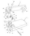
本発明に係るクリップ装置の第1実施形態は、例えば電子機器等の筐体に装着させるものであり、図1〜図3に示すように図示しない筐体に取り付けられるベース部材1と、一端が支軸17を介して連結される開閉部材3と、ベース部材1と開閉部材3との間に配置され、支軸17に介装される弾性付勢部材とを備えている。この弾性付勢部材は、ダブルトーションばね2から成り、ダブルトーションばね2は、両端に形成された固定部2aと、固定部2aの一端に形成された巻回部2bと、これらの各巻回部2bを連結し、開閉部材3に当接する当接部2cとを有している。
[First Embodiment]
1st Embodiment of the clip apparatus concerning this invention is attached to housing | casings, such as an electronic device, for example, and as shown in FIGS. 1-3, the base member 1 attached to the housing | casing which is not shown in figure and one end are shown. An opening /
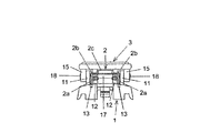
ベース部材1は、ダブルトーションばね2を軸受部11間で圧縮保持する一対の第1の軸受部11と、ダブルトーションばね2の巻回部2bの軸芯方向に直交する方向のうちベース部材1に平行する方向に対してダブルトーションばね2を位置決めする位置決め片12と、一対の第1の軸受部11の内側、例えば第1の軸受部11と位置決め片12との間に穿設され、ダブルトーションばね2の固定部2aの先端を挿入する穴13とを有している。また、一対の第1の軸受部11の間の間隔は、ダブルトーションばね2の巻回部2bの軸芯方向に沿う幅の大きさよりも少し小さく設定されている。
The base member 1 includes a pair of first bearing
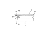
位置決め片12は、ダブルトーションばね2の巻回部2bの形状に沿って半円弧状に形成され、巻回部2bを嵌合する嵌合部12aを有している。開閉部材3は、一対の第1の軸受部11の外側にそれぞれ配置され、一対の第1の軸受部11にそれぞれ対向する一対の第2の軸受部15と、ダブルトーションばね2の当接部2cを支持する支持片20とを含んでいる。そして、ベース部材1の第1の軸受部11はダブルトーションばね2の巻回部2bの軸芯方向に沿う貫通孔11aを有し、開閉部材3の第2の軸受部15は巻回部2bの軸芯方向に沿う貫通孔15aを有している。すなわち、これらの貫通孔11a,15aの位置は、巻回部2bを位置決め片12の嵌合部12aに嵌合させたときに巻回部2bの軸芯と貫通孔11a,15aの軸芯が重なるように設定されている。なお、開閉部材3は、両端のうちベース部材1に対して開閉する側の一端がコ字型に形成され、ベース部材1と開閉部材3との間に配置された物を挟持する挟持部21を有している。
The
そして、本発明の第1実施形態は、第1、第2の軸受部11,15の貫通孔11a,15a及びダブルトーションばね2の巻回部2bの軸芯に挿入する支軸17と、この支軸17を各貫通孔11a,15a及び巻回部2bの軸芯に挿入した状態で貫通孔15aに蓋をするキャップ18とを有している。支軸17は、筒状に形成され、軸芯方向に沿って割れ目が形成されて空芯の軸となっており、この空芯は当該軸の穴径にフィットした軸部品取り付け用の治具棒を通すために用いられる。
And 1st Embodiment of this invention is the
次に、本発明に係るクリップ装置の第1実施形態の動作を説明する。 Next, the operation of the first embodiment of the clip device according to the present invention will be described.
本発明の第1実施形態では、ベース部材1、ダブルトーションばね2、及び開閉部材3を連結部材によって連結する場合、ベース部材1に備えられた第1の軸受部11間にダブルトーションばね2を配置すると、一対の第1の軸受部11の間隔はダブルトーションばね2の巻回部2bの軸芯方向に沿う幅の大きさよりも少し小さく設定されているので、ダブルトーションばね2が第1の軸受部11によって圧縮され、ベース部材1の幅方向に対して動かないように保持される。
In 1st Embodiment of this invention, when connecting the base member 1, the
このとき、ベース部材1の位置決め片12に形成された半円弧状の嵌合部12aにダブルトーションばね2の各巻回部2bを嵌合させると、位置決め片12によってダブルトーションばね2が巻回部2bの軸芯方向に直交する方向のうちベース部材1に平行する方向に対して位置決めされる。これにより、ダブルトーションばね2の各巻回部2bは、軸芯が重なった状態で保持される。さらに、第1の軸受部11の貫通孔11aの位置は、ダブルトーションばね2の各巻回部2bを位置決め片12の嵌合部12aに嵌合させたときに各巻回部2bの軸芯と貫通孔11aの軸芯が重なるように設定されているので、各巻回部2bが位置決め片12に保持されると同時に、各巻回部2bの軸芯及び貫通孔11aの軸芯が重なる。
At this time, when each winding
また、ダブルトーションばね2の各固定部2aの先端を第1の軸受部11と位置決め片12との間に穿設された穴13に挿入することにより、第1の軸受部11の貫通孔11a、開閉部材3の第2の軸受部15の貫通孔15a、及びダブルトーションばね2の各巻回部2bの軸芯に支軸17を挿通させる作業中に各巻回部2bが位置決め片12の嵌合部12aから外れないように固定される。この状態で、開閉部材3の支持片20をダブルトーションばね2の当接部2に当接してダブルトーションばね2を圧縮し、第1、第2の軸受部11,15の貫通孔11a,15a及び各巻回部2bの軸芯に支軸17を挿通させる。そして、図2、図3に示すように、キャップ18によって貫通孔15aに蓋をする。
Further, by inserting the tip of each
このように構成した本発明の第1実施形態は、ベース部材1、ダブルトーションばね2、及び開閉部材3を連結する作業において、ベース部材1の第1の軸受部11間にダブルトーションばね2を圧縮保持させると共に、ベース部材1の位置決め片12の嵌合部12aにダブルトーションばね2の各巻回部2bを嵌合させる簡単な作業を行うだけで各巻回部2bの軸芯及び第1の軸受部11の貫通孔11aの軸芯が重なるようにダブルトーションばね2を配置することができる。
In the first embodiment of the present invention configured as described above, in the operation of connecting the base member 1, the
そして、第2の軸受部15の貫通孔15aの軸芯を巻回部2bの軸芯と合わせるために、開閉部材3の支持片20がダブルトーションばね2の当接部2cを支持した状態で開閉部材3によってダブルトーションばね2をベース部材1に押え付けても、ダブルトーションばね2は、第1の軸受部11、位置決め片12の嵌合部12a、及び穴13に保持されて安定した状態を保つので、各巻回部2bが位置ずれすることなく第1、第2の軸受部11,15の貫通孔11a,15a及び各巻回部2bの軸芯に支軸17を容易に挿通させることができる。このように、ベース部材1、ダブルトーションばね2、及び開閉部材3を連結する作業の工程を少なくすることができ、組立作業を容易に行うことができる。
And in order for the axial center of the through-
また、本発明の第1実施形態は、支軸17は、筒状に形成されており、弾性を有するように軸芯方向に沿って割れ目が形成されているので、第1、第2の軸受部11,15の貫通孔11a,15a及び各巻回部2bの軸芯に支軸17を挿入させると、支軸17が弾性によって動かないように固定される。これにより、装置の安定した構造を実現することができる。
Further, in the first embodiment of the present invention, the
また、本発明の第1実施形態は、支軸17を各貫通孔11a,15a及び巻回部2bの軸芯に挿入した状態で貫通孔15aにキャップ18で蓋をすることにより、装置の意匠性を良くすることができる。
In the first embodiment of the present invention, the
[第2実施形態]
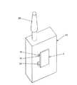
図4は本発明に係るクリップ装置の第2実施形態の構成を示す斜視図である。
[Second Embodiment]
FIG. 4 is a perspective view showing the configuration of the second embodiment of the clip device according to the present invention.
本発明の第2実施形態が前述した第1実施形態と異なるのは、第1実施形態では、ベース部材1を電子機器等の図示しない筐体に装着させる場合について説明したが、図4に示すように第2実施形態では、ベース部材1は、開閉部材3が取り付けられる筐体22から成っていることである。そして、この筐体22は、上面に電波を受信するアンテナ23を有している。その他の構成は第1実施形態と同様である。
The second embodiment of the present invention is different from the first embodiment described above. In the first embodiment, the case where the base member 1 is mounted on a housing (not shown) such as an electronic device has been described. Thus, in 2nd Embodiment, the base member 1 consists of the housing | casing 22 to which the opening / closing
このように構成した本発明の第2実施形態は、ベース部材1が、開閉部材3が取り付けられる筐体22から成っており、開閉部材3とダブルトーションばね2を筐体22に直接取り付けるだけで良いので、ベース部材1を筐体22に取り付ける作業工程を行わなくて済み、装置の組立工数を減らすことができる。これにより、組立作業の効率を向上させることができる。
In the second embodiment of the present invention configured as described above, the base member 1 is composed of a
なお、本発明の第1、第2実施形態は、第1、第2の軸受部11,15の貫通孔11a,15a及びダブルトーションばね2の巻回部2bの軸芯に挿入する支軸17と、この支軸17を各貫通孔11a,15a及び巻回部2bの軸芯に挿入した状態で貫通孔15aに蓋をするキャップ18とを有している場合について説明したが、支軸17及びキャップ18の代わりに、例えばボルト及びナットを有してもよい。
In the first and second embodiments of the present invention, the
1 ベース部材
2 ダブルトーションばね
2a 固定部
2b 巻回部
2c 当接部
3 開閉部材
11 第1の軸受部
11a 貫通孔
12 位置決め片
12a 嵌合部
13 穴
15 第2の軸受部
15a 貫通孔
17 支軸
18 キャップ
20 支持片
21 挟持部
22 筐体
23 アンテナ
DESCRIPTION OF SYMBOLS 1
Claims (2)
前記弾性付勢部材はダブルトーションばねから成り、
前記ベース部材は、前記ダブルトーションばねを前記軸受部間で圧縮保持する一対の前記軸受部と、前記ダブルトーションばねの巻回部の軸芯方向に直交する方向のうち前記ベース部材に平行する方向に対して前記ダブルトーションばねを位置決めする位置決め片と、前記一対の軸受部の内側に穿設され、前記ダブルトーションばねの先端を挿入する穴とを有することを特徴とするクリップ装置。 In a clip device in which a base member and an opening / closing member are connected to both bearing portions via a support shaft, and a holding portion is separated and biased by an elastic biasing member provided between the base member and the opening / closing member ,
The elastic biasing member comprises a double torsion spring,
The base member is a direction parallel to the base member among a pair of the bearing portions compressing and holding the double torsion spring between the bearing portions and a direction perpendicular to the axial direction of the winding portion of the double torsion spring. A clip device comprising: a positioning piece for positioning the double torsion spring with respect to the inner surface; and a hole that is formed inside the pair of bearing portions and into which a tip of the double torsion spring is inserted.
前記ベース部材は、前記開閉部材が取り付けられる筐体から成ることを特徴とするクリップ装置。 The clip device according to claim 1,
The clip device according to claim 1, wherein the base member includes a casing to which the opening / closing member is attached.
Priority Applications (2)
| Application Number | Priority Date | Filing Date | Title |
|---|---|---|---|
| JP2010054890A JP2011190818A (en) | 2010-03-11 | 2010-03-11 | Clip device |
| US12/830,757 US20110219589A1 (en) | 2010-03-11 | 2010-07-06 | Clip Device |
Applications Claiming Priority (1)
| Application Number | Priority Date | Filing Date | Title |
|---|---|---|---|
| JP2010054890A JP2011190818A (en) | 2010-03-11 | 2010-03-11 | Clip device |
Publications (1)
| Publication Number | Publication Date |
|---|---|
| JP2011190818A true JP2011190818A (en) | 2011-09-29 |
Family
ID=44558531
Family Applications (1)
| Application Number | Title | Priority Date | Filing Date |
|---|---|---|---|
| JP2010054890A Pending JP2011190818A (en) | 2010-03-11 | 2010-03-11 | Clip device |
Country Status (2)
| Country | Link |
|---|---|
| US (1) | US20110219589A1 (en) |
| JP (1) | JP2011190818A (en) |
Cited By (6)
| Publication number | Priority date | Publication date | Assignee | Title |
|---|---|---|---|---|
| JP2013179125A (en) * | 2012-02-28 | 2013-09-09 | Icom Inc | Mounting structure of access cover |
| JP2015146350A (en) * | 2014-01-31 | 2015-08-13 | シャープ株式会社 | Opening and closing device |
| JP2015177846A (en) * | 2014-03-19 | 2015-10-08 | 日本光電工業株式会社 | Clip electrode |
| KR101617856B1 (en) | 2014-03-03 | 2016-05-03 | 김용국 | Fixing equipment using H beam |
| JP2021109318A (en) * | 2020-01-07 | 2021-08-02 | 株式会社マグエックス | Magnet clip |
| JP2021170972A (en) * | 2020-04-23 | 2021-11-01 | バスデイ株式会社 | Lure |
Families Citing this family (8)
| Publication number | Priority date | Publication date | Assignee | Title |
|---|---|---|---|---|
| US9361873B2 (en) * | 2011-01-21 | 2016-06-07 | Salvatore G. Cicero | Spring loaded device that opens up when force is applied and closes when released |
| US9067545B2 (en) * | 2012-06-18 | 2015-06-30 | The Boeing Company | Spring clip for use in a bracket assembly |
| US10128887B2 (en) * | 2016-03-10 | 2018-11-13 | Vitec Holdings Italia Srl | Multi-configuration clamp system for electronic device |
| CN212644191U (en) * | 2020-04-23 | 2021-03-02 | 深圳市大疆创新科技有限公司 | Clip and electronic equipment assembly |
| US20230322165A1 (en) * | 2022-04-07 | 2023-10-12 | Legit Innovations Llc | Clip for holding articles and structural assembly equipped with clip |
| WO2024243351A2 (en) * | 2023-05-24 | 2024-11-28 | John Peterson | Clip for holding articles and structural assembly equipped with clip |
| US20240410404A1 (en) * | 2023-05-24 | 2024-12-12 | John Peterson | Clip for holding articles and structural assembly equipped with clip |
| USD1098589S1 (en) * | 2025-03-21 | 2025-10-14 | Xiaohuai Zhang | Hair clip |
Family Cites Families (14)
| Publication number | Priority date | Publication date | Assignee | Title |
|---|---|---|---|---|
| US4083481A (en) * | 1977-03-10 | 1978-04-11 | Motorola, Inc. | Detachable mounting clip arrangement for miniature portable apparatus or the like |
| US4536925A (en) * | 1983-10-11 | 1985-08-27 | Motorola, Inc. | Belt clip assembly with a controlled failure mode |
| US4780934A (en) * | 1986-11-21 | 1988-11-01 | Maxcom Electronics, Inc. | Clip mechanism for pager |
| JPH066632Y2 (en) * | 1986-12-25 | 1994-02-16 | 日本電気株式会社 | Detachable clip fixing structure |
| US4741074A (en) * | 1987-01-07 | 1988-05-03 | Motorola, Inc. | Detachable belt clip suitable for automated assembly |
| JPH0739267Y2 (en) * | 1987-07-10 | 1995-09-06 | 日本電気株式会社 | Portable holder housing |
| US4887753A (en) * | 1988-11-21 | 1989-12-19 | Cincinnati Microwave, Inc. | Visor clip for mounting radar detector |
| US5235728A (en) * | 1992-07-30 | 1993-08-17 | H.M. Electronics, Inc. | Fastening device for portable equipment and method of using same |
| US5452497A (en) * | 1993-11-30 | 1995-09-26 | Peng; Jung C. | Multi-purpose fixing seat for belts |
| KR0122491B1 (en) * | 1994-12-28 | 1997-11-19 | 김광호 | Double locking device of belt clip |
| US6101689A (en) * | 1999-09-01 | 2000-08-15 | Jo; Alejandro | Double clip with self-adjusting jaw |
| US6386408B1 (en) * | 2000-07-17 | 2002-05-14 | Clear Clip, Inc. | Transparent securement clip for a vehicle visor |
| US7513472B2 (en) * | 2007-07-10 | 2009-04-07 | Shang-Wen Yang | Adjustable stand |
| US20090144943A1 (en) * | 2007-12-11 | 2009-06-11 | Manuel Arranz Del Rosal | Interchangeable electronic device clip |
-
2010
- 2010-03-11 JP JP2010054890A patent/JP2011190818A/en active Pending
- 2010-07-06 US US12/830,757 patent/US20110219589A1/en not_active Abandoned
Cited By (7)
| Publication number | Priority date | Publication date | Assignee | Title |
|---|---|---|---|---|
| JP2013179125A (en) * | 2012-02-28 | 2013-09-09 | Icom Inc | Mounting structure of access cover |
| JP2015146350A (en) * | 2014-01-31 | 2015-08-13 | シャープ株式会社 | Opening and closing device |
| KR101617856B1 (en) | 2014-03-03 | 2016-05-03 | 김용국 | Fixing equipment using H beam |
| JP2015177846A (en) * | 2014-03-19 | 2015-10-08 | 日本光電工業株式会社 | Clip electrode |
| JP2021109318A (en) * | 2020-01-07 | 2021-08-02 | 株式会社マグエックス | Magnet clip |
| JP2021170972A (en) * | 2020-04-23 | 2021-11-01 | バスデイ株式会社 | Lure |
| JP7429434B2 (en) | 2020-04-23 | 2024-02-08 | バスデイ株式会社 | lure |
Also Published As
| Publication number | Publication date |
|---|---|
| US20110219589A1 (en) | 2011-09-15 |
Similar Documents
| Publication | Publication Date | Title |
|---|---|---|
| JP2011190818A (en) | Clip device | |
| US8421289B2 (en) | Surface mount motor having holder with stopper portion for bracket | |
| CN101443986B (en) | Motor with reducer and manufacturing method thereof | |
| US4037125A (en) | Small-sized direct current rotary electric appliance | |
| US20110291510A1 (en) | Surface mount motor | |
| JP4220545B2 (en) | Stepping motor for convenient assembly | |
| JP3523546B2 (en) | Small motor | |
| JP2014204477A (en) | Brushless motor and coil terminal holding method | |
| US6495939B1 (en) | Coreless motor having tubular housing with end mounting portions | |
| JP5855303B1 (en) | Spacer and spacer design method | |
| TWI270233B (en) | Movable antenna and electronic machine having the same | |
| JP4361949B2 (en) | Brush holder for electric machine | |
| JP5600178B2 (en) | Tuning element assembly and method for RF components | |
| JP3660598B2 (en) | Brush holding method and apparatus for small motor | |
| JP3569463B2 (en) | motor | |
| CN214560563U (en) | A shaft snap ring installation tool | |
| JP2009148123A (en) | Rotating electrical machine | |
| JP4980515B2 (en) | Electric motors specified for fixing on printed wiring boards | |
| JP2005118856A (en) | Device and method for joining and fixing with crimp, structure joined and fixed with crimp, and motor for wiper | |
| JP5207790B2 (en) | motor | |
| JP3955850B2 (en) | Manufacturing method of motor | |
| US12388313B2 (en) | Rotary electric machine and electric actuator | |
| KR200481038Y1 (en) | Clamping jig for stator of the motor housing | |
| US12218563B2 (en) | Motor | |
| CN220041942U (en) | Battery shrapnel curling jig |