JP2011165402A - Anode for lithium ion secondary battery, lithium ion secondary battery, power tool, electric vehicle, and power storage system - Google Patents
Anode for lithium ion secondary battery, lithium ion secondary battery, power tool, electric vehicle, and power storage system Download PDFInfo
- Publication number
- JP2011165402A JP2011165402A JP2010024583A JP2010024583A JP2011165402A JP 2011165402 A JP2011165402 A JP 2011165402A JP 2010024583 A JP2010024583 A JP 2010024583A JP 2010024583 A JP2010024583 A JP 2010024583A JP 2011165402 A JP2011165402 A JP 2011165402A
- Authority
- JP
- Japan
- Prior art keywords
- negative electrode
- active material
- electrode active
- layer
- secondary battery
- Prior art date
- Legal status (The legal status is an assumption and is not a legal conclusion. Google has not performed a legal analysis and makes no representation as to the accuracy of the status listed.)
- Pending
Links
Images


Classifications
-
- H—ELECTRICITY
- H01—ELECTRIC ELEMENTS
- H01M—PROCESSES OR MEANS, e.g. BATTERIES, FOR THE DIRECT CONVERSION OF CHEMICAL ENERGY INTO ELECTRICAL ENERGY
- H01M4/00—Electrodes
- H01M4/02—Electrodes composed of, or comprising, active material
- H01M4/13—Electrodes for accumulators with non-aqueous electrolyte, e.g. for lithium-accumulators; Processes of manufacture thereof
- H01M4/134—Electrodes based on metals, Si or alloys
-
- H—ELECTRICITY
- H01—ELECTRIC ELEMENTS
- H01M—PROCESSES OR MEANS, e.g. BATTERIES, FOR THE DIRECT CONVERSION OF CHEMICAL ENERGY INTO ELECTRICAL ENERGY
- H01M10/00—Secondary cells; Manufacture thereof
- H01M10/05—Accumulators with non-aqueous electrolyte
- H01M10/052—Li-accumulators
-
- H—ELECTRICITY
- H01—ELECTRIC ELEMENTS
- H01M—PROCESSES OR MEANS, e.g. BATTERIES, FOR THE DIRECT CONVERSION OF CHEMICAL ENERGY INTO ELECTRICAL ENERGY
- H01M10/00—Secondary cells; Manufacture thereof
- H01M10/05—Accumulators with non-aqueous electrolyte
- H01M10/052—Li-accumulators
- H01M10/0525—Rocking-chair batteries, i.e. batteries with lithium insertion or intercalation in both electrodes; Lithium-ion batteries
-
- H—ELECTRICITY
- H01—ELECTRIC ELEMENTS
- H01M—PROCESSES OR MEANS, e.g. BATTERIES, FOR THE DIRECT CONVERSION OF CHEMICAL ENERGY INTO ELECTRICAL ENERGY
- H01M4/00—Electrodes
- H01M4/02—Electrodes composed of, or comprising, active material
- H01M4/36—Selection of substances as active materials, active masses, active liquids
- H01M4/362—Composites
- H01M4/366—Composites as layered products
-
- H—ELECTRICITY
- H01—ELECTRIC ELEMENTS
- H01M—PROCESSES OR MEANS, e.g. BATTERIES, FOR THE DIRECT CONVERSION OF CHEMICAL ENERGY INTO ELECTRICAL ENERGY
- H01M4/00—Electrodes
- H01M4/02—Electrodes composed of, or comprising, active material
- H01M4/36—Selection of substances as active materials, active masses, active liquids
- H01M4/38—Selection of substances as active materials, active masses, active liquids of elements or alloys
- H01M4/386—Silicon or alloys based on silicon
-
- H—ELECTRICITY
- H01—ELECTRIC ELEMENTS
- H01M—PROCESSES OR MEANS, e.g. BATTERIES, FOR THE DIRECT CONVERSION OF CHEMICAL ENERGY INTO ELECTRICAL ENERGY
- H01M4/00—Electrodes
- H01M4/02—Electrodes composed of, or comprising, active material
- H01M4/64—Carriers or collectors
- H01M4/66—Selection of materials
- H01M4/661—Metal or alloys, e.g. alloy coatings
- H01M4/662—Alloys
-
- H—ELECTRICITY
- H01—ELECTRIC ELEMENTS
- H01M—PROCESSES OR MEANS, e.g. BATTERIES, FOR THE DIRECT CONVERSION OF CHEMICAL ENERGY INTO ELECTRICAL ENERGY
- H01M4/00—Electrodes
- H01M4/02—Electrodes composed of, or comprising, active material
- H01M4/64—Carriers or collectors
- H01M4/66—Selection of materials
- H01M4/665—Composites
- H01M4/667—Composites in the form of layers, e.g. coatings
-
- H—ELECTRICITY
- H01—ELECTRIC ELEMENTS
- H01M—PROCESSES OR MEANS, e.g. BATTERIES, FOR THE DIRECT CONVERSION OF CHEMICAL ENERGY INTO ELECTRICAL ENERGY
- H01M4/00—Electrodes
- H01M4/02—Electrodes composed of, or comprising, active material
- H01M4/64—Carriers or collectors
- H01M4/70—Carriers or collectors characterised by shape or form
-
- H—ELECTRICITY
- H01—ELECTRIC ELEMENTS
- H01M—PROCESSES OR MEANS, e.g. BATTERIES, FOR THE DIRECT CONVERSION OF CHEMICAL ENERGY INTO ELECTRICAL ENERGY
- H01M10/00—Secondary cells; Manufacture thereof
- H01M10/05—Accumulators with non-aqueous electrolyte
- H01M10/056—Accumulators with non-aqueous electrolyte characterised by the materials used as electrolytes, e.g. mixed inorganic/organic electrolytes
- H01M10/0564—Accumulators with non-aqueous electrolyte characterised by the materials used as electrolytes, e.g. mixed inorganic/organic electrolytes the electrolyte being constituted of organic materials only
- H01M10/0566—Liquid materials
- H01M10/0567—Liquid materials characterised by the additives
-
- H—ELECTRICITY
- H01—ELECTRIC ELEMENTS
- H01M—PROCESSES OR MEANS, e.g. BATTERIES, FOR THE DIRECT CONVERSION OF CHEMICAL ENERGY INTO ELECTRICAL ENERGY
- H01M10/00—Secondary cells; Manufacture thereof
- H01M10/05—Accumulators with non-aqueous electrolyte
- H01M10/056—Accumulators with non-aqueous electrolyte characterised by the materials used as electrolytes, e.g. mixed inorganic/organic electrolytes
- H01M10/0564—Accumulators with non-aqueous electrolyte characterised by the materials used as electrolytes, e.g. mixed inorganic/organic electrolytes the electrolyte being constituted of organic materials only
- H01M10/0566—Liquid materials
- H01M10/0569—Liquid materials characterised by the solvents
-
- Y—GENERAL TAGGING OF NEW TECHNOLOGICAL DEVELOPMENTS; GENERAL TAGGING OF CROSS-SECTIONAL TECHNOLOGIES SPANNING OVER SEVERAL SECTIONS OF THE IPC; TECHNICAL SUBJECTS COVERED BY FORMER USPC CROSS-REFERENCE ART COLLECTIONS [XRACs] AND DIGESTS
- Y02—TECHNOLOGIES OR APPLICATIONS FOR MITIGATION OR ADAPTATION AGAINST CLIMATE CHANGE
- Y02E—REDUCTION OF GREENHOUSE GAS [GHG] EMISSIONS, RELATED TO ENERGY GENERATION, TRANSMISSION OR DISTRIBUTION
- Y02E60/00—Enabling technologies; Technologies with a potential or indirect contribution to GHG emissions mitigation
- Y02E60/10—Energy storage using batteries
-
- Y—GENERAL TAGGING OF NEW TECHNOLOGICAL DEVELOPMENTS; GENERAL TAGGING OF CROSS-SECTIONAL TECHNOLOGIES SPANNING OVER SEVERAL SECTIONS OF THE IPC; TECHNICAL SUBJECTS COVERED BY FORMER USPC CROSS-REFERENCE ART COLLECTIONS [XRACs] AND DIGESTS
- Y02—TECHNOLOGIES OR APPLICATIONS FOR MITIGATION OR ADAPTATION AGAINST CLIMATE CHANGE
- Y02T—CLIMATE CHANGE MITIGATION TECHNOLOGIES RELATED TO TRANSPORTATION
- Y02T10/00—Road transport of goods or passengers
- Y02T10/60—Other road transportation technologies with climate change mitigation effect
- Y02T10/70—Energy storage systems for electromobility, e.g. batteries
Abstract
Description
本発明は、構成元素として珪素(Si)を含有する負極活物質を含むリチウムイオン二次電池用負極、およびそれを備えたリチウムイオン二次電池、ならびにそれを用いた電動工具、電気自動車および電力貯蔵システムに関する。 The present invention relates to a negative electrode for a lithium ion secondary battery including a negative electrode active material containing silicon (Si) as a constituent element, a lithium ion secondary battery including the same, an electric tool using the same, an electric vehicle, and electric power Relates to storage systems.
近年、カメラ一体型VTR(video tape recorder )、携帯電話あるいはノートパソコンなどのポータブル電子機器が広く普及しており、その小型化、軽量化および長寿命化が強く求められている。これに伴い、ポータブル電子機器の電源として、電池、特に軽量で高エネルギー密度が得られる二次電池の開発が進められている。このような二次電池は、最近では、小型の電子機器に限らず、電気自動車などに代表される大型の電子機器への適用も検討されている。 In recent years, portable electronic devices such as a camera-integrated VTR (video tape recorder), a mobile phone, or a laptop computer have been widely used, and there is a strong demand for miniaturization, weight reduction, and long life. Accordingly, as a power source for portable electronic devices, development of a battery, in particular, a secondary battery that is lightweight and obtains a high energy density is in progress. Recently, such secondary batteries are not limited to small electronic devices, but are also being considered for application to large electronic devices such as electric vehicles.
中でも、充放電反応にリチウムの吸蔵および放出を利用する二次電池(いわゆるリチウムイオン二次電池)は、鉛電池やニッケルカドミウム電池よりも大きなエネルギー密度が得られるため、大いに期待されている。 Among them, a secondary battery (so-called lithium ion secondary battery) that uses insertion and extraction of lithium for charge and discharge reactions is highly expected because a higher energy density can be obtained than a lead battery or a nickel cadmium battery.
このリチウムイオン二次電池は、負極活物質を含む負極活物質層が負極集電体に設けられた構成を有する負極を備えている。この負極活物質としては炭素材料が広く用いられているが、最近では、ポータブル電子機器の高性能化および多機能化に伴って電池容量のさらなる向上が求められていることから、炭素材料に代えて珪素を用いることが検討されている。珪素の理論容量(4199mAh/g)は黒鉛の理論容量(372mAh/g)よりも格段に大きいため、電池容量の大幅な向上が期待されるからである。 This lithium ion secondary battery includes a negative electrode having a configuration in which a negative electrode active material layer including a negative electrode active material is provided on a negative electrode current collector. As this negative electrode active material, a carbon material is widely used. However, in recent years, a further improvement in battery capacity has been demanded along with higher performance and multi-functionality of portable electronic devices. Therefore, the use of silicon has been studied. This is because the theoretical capacity of silicon (4199 mAh / g) is much larger than the theoretical capacity of graphite (372 mAh / g), so that a significant improvement in battery capacity is expected.
ところが、気相法によって負極活物質として珪素を堆積させることにより負極活物質層を形成した場合には、その結着性が十分でないため、充放電を繰り返すと、負極活物質層が激しく膨張および収縮して粉砕するおそれがある。負極活物質層が粉砕すると、その粉砕の程度によっては表面積の増大に起因して不可逆性のリチウム酸化物が形成されすぎると共に負極集電体からの崩落に起因して集電性が低下するため、二次電池の重要な特性であるサイクル特性が低下してしまう。 However, when a negative electrode active material layer is formed by depositing silicon as a negative electrode active material by a vapor phase method, the binding properties thereof are not sufficient. There is a risk of shrinking and crushing. When the negative electrode active material layer is pulverized, depending on the degree of pulverization, excessively irreversible lithium oxide is formed due to an increase in surface area, and current collecting performance is reduced due to collapse from the negative electrode current collector. The cycle characteristics, which are important characteristics of the secondary battery, are degraded.
そこで、負極活物質として珪素を用いた場合においてもサイクル特性を向上させるために、さまざまな工夫がなされている。具体的には、気相法において複数回に分けて珪素を堆積させ、負極活物質層を多層構造とする技術が開示されている(例えば、特許文献1)。これ以外にも、鉄、コバルト、ニッケル、亜鉛あるいは銅などの金属で負極活物質の表面を被覆する技術(例えば、特許文献2参照。)や、リチウムと合金化しない銅などの金属元素を負極活物質中に拡散させる技術(例えば、特許文献3参照。)や、負極活物質に銅を固溶させる技術(例えば、特許文献4参照。)などが提案されている。この他、本出願人は、珪素を含み、かつ、酸素の含有量が異なる第1層と第2層とを交互に積層させた多層構造を備えることにより、負極活物質層の激しい膨張および収縮を抑制し、その構造破壊を抑制するようにした技術も開示している(例えば、特許文献5参照)。 Therefore, various ideas have been made to improve cycle characteristics even when silicon is used as the negative electrode active material. Specifically, a technique in which silicon is deposited in a plurality of times in a vapor phase method to form a negative electrode active material layer having a multilayer structure is disclosed (for example, Patent Document 1). In addition to this, a technique for coating the surface of the negative electrode active material with a metal such as iron, cobalt, nickel, zinc, or copper (see, for example, Patent Document 2), or a metal element such as copper that does not alloy with lithium is used as the negative electrode. A technique for diffusing into an active material (for example, see Patent Document 3), a technique for dissolving copper in a negative electrode active material (for example, see Patent Document 4), and the like have been proposed. In addition, the applicant of the present invention provides a multilayer structure in which the first layer and the second layer containing silicon and having different oxygen contents are alternately stacked, thereby causing severe expansion and contraction of the negative electrode active material layer. Further, there is also disclosed a technique that suppresses the structural destruction and suppresses the structural breakdown (see, for example, Patent Document 5).
しかしながら、最近のポータブル電子機器は益々小型化、高性能化および多機能化しており、それに伴って二次電池の充放電が頻繁に繰り返される傾向にあるため、サイクル特性が低下しやすい状況にある。特に、高容量化のために負極活物質として珪素を用いたリチウムイオン二次電池では、上記した充放電時における負極活物質層の粉砕の影響を受けてサイクル特性が顕著に低下しやすい。このため、二次電池のサイクル特性に関してより一層の向上が望まれている。 However, recent portable electronic devices are becoming smaller, higher performance, and more multifunctional, and accordingly, charging and discharging of secondary batteries tend to be repeated frequently, so that cycle characteristics are likely to deteriorate. . In particular, in a lithium ion secondary battery using silicon as a negative electrode active material in order to increase the capacity, the cycle characteristics are likely to be significantly lowered due to the influence of the pulverization of the negative electrode active material layer during charge / discharge. For this reason, the further improvement regarding the cycling characteristics of a secondary battery is desired.
本発明はかかる問題点に鑑みてなされたもので、その目的は、サイクル特性を向上させることが可能なリチウムイオン二次電池用負極およびそれを用いたリチウムイオン二次電池を提供することにある。また、上記のリチウムイオン二次電池を用いた電動工具、電気自動車および電力貯蔵システムを提供することにある。 The present invention has been made in view of such problems, and an object thereof is to provide a negative electrode for a lithium ion secondary battery capable of improving cycle characteristics and a lithium ion secondary battery using the same. . Moreover, it is providing the electric tool, electric vehicle, and electric power storage system using said lithium ion secondary battery.
本発明のリチウムイオン二次電池用負極は、負極集電体上に、珪素および金属元素を負極活物質として各々含有する第1および第2の層が交互に積層されてなる負極活物質層を有し、かつ、条件式(1)を満足するものである。但し、Aは第1の層における負極活物質中の珪素含有率であり、Bは第2の層における負極活物質中の珪素含有率である。 The negative electrode for a lithium ion secondary battery of the present invention comprises a negative electrode active material layer in which first and second layers each containing silicon and a metal element as a negative electrode active material are alternately laminated on a negative electrode current collector. And satisfying conditional expression (1). However, A is the silicon content in the negative electrode active material in the first layer, and B is the silicon content in the negative electrode active material in the second layer.
1.02≦A/B≦50 ……(1) 1.02 ≦ A / B ≦ 50 (1)
また、本発明のリチウムイオン二次電池は、正極および上記の本発明のリチウムイオン二次電池用負極と共に電解質を備えるようにしたものである。さらに、本発明の電動工具、電気自動車および電力貯蔵システムは、上記のリチウムイオン二次電池を電源あるいは電力貯蔵源として用いるようにしたものである。 Moreover, the lithium ion secondary battery of this invention is equipped with an electrolyte with a positive electrode and said negative electrode for lithium ion secondary batteries of this invention. Furthermore, the electric tool, the electric vehicle, and the power storage system of the present invention are such that the lithium ion secondary battery is used as a power source or a power storage source.
本発明のリチウムイオン二次電池用負極、リチウムイオン二次電池、電動工具、電気自動車および電力貯蔵システムでは、負極活物質層が珪素および金属元素を各々含有する第1の層および第2の層を交互に積層したものであり、かつ、それら第1および第2の層における負極活物質中の珪素含有率が所定の条件式(1)を満足する関係にある。これにより、負極活物質層での充放電時における膨張および収縮に伴う応力が緩和される。 In the negative electrode for a lithium ion secondary battery, the lithium ion secondary battery, the electric tool, the electric vehicle, and the power storage system of the present invention, the negative electrode active material layer includes a first layer and a second layer containing silicon and a metal element, respectively. Are alternately stacked, and the silicon content in the negative electrode active material in the first and second layers satisfies the predetermined conditional expression (1). Thereby, the stress accompanying expansion | swelling and shrinkage | contraction at the time of charging / discharging in a negative electrode active material layer is relieve | moderated.
本発明のリチウムイオン二次電池用負極によれば、負極活物質層の構成要素である第1および第2の層が、珪素(Si)および金属元素を負極活物質として含有し、かつ、各々の負極活物質中の珪素含有率が条件式(1)を満足する。こうすることにより、負極活物質層の構造破壊が抑制されると共に、第1および第2の層を含む積層構造における各層間の密着性、ならびに負極活物質層と負極集電体との密着性および集電性が向上する。そのため、このリチウムイオン二次電池用負極をリチウムイオン二次電池に適用すれば、負極活物質として珪素を用いることで高容量化を図りつつ、優れたサイクル特性をも得ることができる。また、本発明の電動工具、電気自動車および電力貯蔵システムによれば、サイクル特性に優れたリチウムイオン二次電池を用いるようにしたので、より長期間に亘る使用が可能となる。 According to the negative electrode for a lithium ion secondary battery of the present invention, the first and second layers that are constituent elements of the negative electrode active material layer contain silicon (Si) and a metal element as the negative electrode active material, and The silicon content in the negative electrode active material satisfies the conditional expression (1). By doing so, structural destruction of the negative electrode active material layer is suppressed, adhesion between the layers in the laminated structure including the first and second layers, and adhesion between the negative electrode active material layer and the negative electrode current collector In addition, current collection is improved. Therefore, if this negative electrode for a lithium ion secondary battery is applied to a lithium ion secondary battery, excellent cycle characteristics can be obtained while increasing the capacity by using silicon as the negative electrode active material. Moreover, according to the electric tool, the electric vehicle, and the power storage system of the present invention, since the lithium ion secondary battery having excellent cycle characteristics is used, it can be used for a longer period of time.
以下、本発明を実施するための形態(以下、実施の形態という。)について、図面を参照して詳細に説明する。なお、説明は以下の順序で行う。
1.第1の実施の形態(負極:負極活物質層が粒子状でない場合の例)
2.第2の実施の形態(負極:負極活物質層が粒子状である場合の例)
3.第3の実施の形態(上記負極を備えた第1〜第3の二次電池の例)
3−1.第1の二次電池(円筒型)
3−2.第2の二次電池(ラミネートフィルム型)
3−3.第3の二次電池(角型)
4.リチウムイオン二次電池の用途
Hereinafter, modes for carrying out the present invention (hereinafter referred to as embodiments) will be described in detail with reference to the drawings. The description will be given in the following order.
1. First Embodiment (Negative electrode: Example in which negative electrode active material layer is not particulate)
2. Second Embodiment (Negative Electrode: Example when Negative Electrode Active Material Layer is Particulate)
3. Third embodiment (examples of first to third secondary batteries including the negative electrode)
3-1. First secondary battery (cylindrical type)
3-2. Second secondary battery (laminate film type)
3-3. Third secondary battery (square type)
4). Applications of lithium ion secondary batteries
[1.第1の実施の形態]
<負極の構成>
図1は、本発明の第1の実施の形態としてのリチウムイオン二次電池用負極(以下単に「負極」という。)10における概略断面構成を表している。負極10は、電池などの電気化学デバイスに用いられるものであり、例えば負極集電体101の表面に負極活物質層102が設けられた構造を有している。なお、負極活物質層102は、図1に示したように負極集電体101の両面に設けてもよいし、あるいは一方の面のみに設けてもよい。
[1. First Embodiment]
<Configuration of negative electrode>
FIG. 1 shows a schematic cross-sectional configuration of a negative electrode for a lithium ion secondary battery (hereinafter simply referred to as “negative electrode”) 10 as a first embodiment of the present invention. The
負極集電体101は、良好な電気化学的安定性、電気伝導性および機械的強度を有する金属材料により構成されているのが好ましい。この金属材料としては、例えば、銅(Cu)、ニッケル(Ni)あるいはステンレスなどが挙げられる。中でも、金属材料としては、銅が好ましい。高い電気伝導性が得られるからである。
The negative electrode
特に、負極集電体101を構成する金属材料としては、電極反応物質と金属間酸化物を形成しない1種あるいは2種以上の金属元素を含有するものが好ましい。電極反応物質と金属間酸化物を形成すると、充放電時における負極活物質層102の膨張および収縮による応力の影響を受けて破損するため、集電性が低下したり負極活物質層102が剥離したりしやすくなるからである。この金属元素としては、例えば、銅、ニッケル、チタン(Ti)、鉄(Fe)あるいはクロム(Cr)などが挙げられる。
In particular, the metal material constituting the negative electrode
また、上記した金属材料としては、負極活物質層102と合金化する1種あるいは2種以上の金属元素を含有するものが好ましい。負極集電体101と負極活物質層102との間の密着性が向上するため、その負極活物質層102が負極集電体101から剥離しにくくなるからである。電極反応物質と金属間酸化物を形成せず、しかも負極活物質層102と合金化する金属元素としては、例えば、負極活物質層102の負極活物質が珪素(Si)を有する場合には、銅、ニッケルあるいは鉄などが挙げられる。これらの金属元素は、強度および導電性の観点からも好ましい。
Further, as the above-described metal material, a material containing one or more metal elements that are alloyed with the negative electrode
なお、負極集電体101は、単層構造を有していてもよいし、多層構造を有していてもよい。この負極集電体101が多層構造を有する場合には、例えば、負極活物質層102と隣接する層がそれと合金化する金属材料によって構成される一方で、隣接しない層が他の金属材料によって構成されるのが好ましい。
Note that the negative electrode
負極集電体101の表面は、粗面化されているのが好ましい。いわゆるアンカー効果によって負極集電体101と負極活物質層102との間の密着性が向上するからである。この場合には、少なくとも負極活物質層102と対向する負極集電体101の表面が粗面化されていればよい。粗面化の方法としては、例えば、電解処理によって微粒子を形成する方法などが挙げられる。この電解処理とは、電解槽中において電解法によって負極集電体101の表面に微粒子を形成することにより凹凸を設ける方法である。この電解処理が施された銅箔は、一般に「電解銅箔」と呼ばれている。
The surface of the negative electrode
この負極集電体101の表面の十点平均粗さRzは、例えば1.5μm以上6.5μm以下の範囲内であるのが好ましい。負極集電体1と負極活物質層102との間の密着性がより高くなるからである。
The ten-point average roughness Rz of the surface of the negative electrode
図2は、負極活物質層102の詳細な断面構成を表すものである。負極活物質層102は、図2に示したように、第1の層1と第2の層2とが繰り返し積層されてなる多層構造を有する。第1の層1および第2の層2は、いずれも珪素(Si)および金属元素Xを構成元素とする負極活物質を各々含有する。但し、第1の層1と第2の層2とでは、負極活物質中の珪素含有率が互いに異なっている。例えば、第1の層1における負極活物質中の珪素含有率Aおよび第2の層における負極活物質中の珪素含有率Bは、下記の条件式(1)を満足する関係にある。例えば、珪素含有率Bは1.8原子数%以上88原子数%以下であり、第1の層における負極活物質中の珪素含有率Aは原子数70%以上90原子数%以下が好ましい。
FIG. 2 illustrates a detailed cross-sectional configuration of the negative electrode
1.02≦A/B≦50 ……(1) 1.02 ≦ A / B ≦ 50 (1)
また、第1の層1の厚さCは、例えば0.04μm以上16μm以下であることが望ましく、第2の層2の厚さDは、例えば0.01μm以上4μm以下であることが望ましい。ここで、厚さCおよび厚さDは、下記の条件式(2)を満足する関係にある。
The thickness C of the
0.1≦C/D≦40 ……(2) 0.1 ≦ C / D ≦ 40 (2)
厚さCおよび厚さDは互いに等しくてもよいし、互いに異なっていてもよい。なお、図2では、負極集電体101の側から順に第1の層1と第2の層2とが交互に積層された構成を例示したが、本実施の形態では、その反対の順序、すなわち負極集電体101の側から第2の層2と第1の層1とが交互に積層された構成としてもよい。また、多層構造に含まれる第1の層1および第2の層2の各々の積層数は、図2に示したものに限定されない。
The thickness C and the thickness D may be equal to each other or may be different from each other. 2 illustrates the configuration in which the
金属元素Xとしては、例えばニッケル,コバルト,鉄,マンガン(Mn),クロム,チタン,アルミニウム(Al),マグネシウム(Mg)およびモリブデン(Mo)のうちの少なくとも1種を有していることが望ましい。負極活物質における金属元素Xの存在は、負極活物質層102の膨張および収縮の抑制に寄与する。特に、珪素および金属元素Xの組成が互いに異なる第1の層1および第2の層2が交互に積層されることにより、負極活物質層102の膨張および収縮がいっそう抑制される。
As the metal element X, for example, it is desirable to have at least one of nickel, cobalt, iron, manganese (Mn), chromium, titanium, aluminum (Al), magnesium (Mg), and molybdenum (Mo). . The presence of the metal element X in the negative electrode active material contributes to suppression of expansion and contraction of the negative electrode
負極活物質の構成元素である珪素は、電極反応物質としてのリチウムを吸蔵および放出する能力が大きく、高いエネルギー密度を得ることができる。 Silicon, which is a constituent element of the negative electrode active material, has a large ability to occlude and release lithium as an electrode reactant and can obtain a high energy density.
第1の層1および第2の層2において、珪素は、単体のほか、合金や化合物として負極活物質に含まれていてもよい。あるいは、負極活物質は、珪素の単体、合金もしくは化合物の1種あるいは2種以上の相を少なくとも一部に有するものであってもよい。これらは単独で用いられてもよいし、複数種が混合されて用いられてよい。なお、本実施の形態における合金には、2種以上の金属元素からなるものに加えて、1種以上の金属元素と1種以上の半金属元素とを含むものも含まれる。もちろん、本実施の形態における合金は、非金属元素を含んでいてもよい。その組織には、固溶体、共晶(共融混合物)、金属間化合物あるいはそれらの2種以上が共存するものもある。
In the
珪素の合金としては、例えば、珪素以外の他の構成元素として、上述の金属元素Xとして挙げたニッケル,コバルト,鉄,マンガン,クロム,チタン,アルミニウム,マグネシウムおよびモリブデンのほか、スズ(Sn),銅,亜鉛(Zn),インジウム(In),銀(Ag),ゲルマニウム(Ge),ビスマス(Bi),アンチモン(Sb),砒素(As)およびカルシウム(Ca)からなる群のうちの少なくとも1種を含むものが挙げられる。特に、鉄、コバルト、ニッケル、ゲルマニウム、スズ、砒素、亜鉛、銅、チタン、クロム、マグネシウム、カルシウム、アルミニウムまたは銀を他の構成元素として負極活物質に適量加えることで、珪素の単体からなる負極活物質と比べ、エネルギー密度の向上が見込まれる。 As an alloy of silicon, for example, as a constituent element other than silicon, in addition to nickel, cobalt, iron, manganese, chromium, titanium, aluminum, magnesium and molybdenum mentioned as the metal element X, tin (Sn), At least one selected from the group consisting of copper, zinc (Zn), indium (In), silver (Ag), germanium (Ge), bismuth (Bi), antimony (Sb), arsenic (As), and calcium (Ca) The thing containing is mentioned. In particular, a negative electrode made of a simple substance of silicon by adding an appropriate amount of iron, cobalt, nickel, germanium, tin, arsenic, zinc, copper, titanium, chromium, magnesium, calcium, aluminum, or silver as another constituent element to the negative electrode active material. The energy density is expected to improve compared to the active material.
珪素の化合物としては、例えば、珪素以外の構成元素として炭素(C)を有するものなどが挙げられる。なお、珪素の化合物は、例えば、珪素以外の構成元素として、上述した他の構成元素の1種あるいは2種以上を含んでいてもよい。 Examples of the silicon compound include those having carbon (C) as a constituent element other than silicon. In addition, the compound of silicon may contain 1 type, or 2 or more types of the other structural element mentioned above as structural elements other than silicon, for example.
負極活物質層102は、例えば塗布法、気相法、液相法、溶射法、焼成法あるいはそれらの2種以上の方法を用いて形成されている。特に、気相法を用いて複数回に亘る堆積工程を経ることによって形成され、負極活物質層102が負極集電体101との界面の少なくとも一部において合金化しているのが好ましい。具体的には、両者の界面において、負極集電体101の構成元素が負極活物質層102に拡散していてもよいし、負極活物質層102の構成元素が負極集電体101に拡散していてもよいし、両者の構成元素が互いに拡散しあっていてもよい。充放電時の膨張および収縮に起因して負極活物質層102が破損しにくくなると共に、負極集電体101と負極活物質層102との間において電子伝導性が向上するからである。
The negative electrode
金属元素Xについては、例えば気相法として蒸着法を用いて負極活物質を堆積させる際に、その金属元素Xを混合させた蒸着源を用いたり、多元系の蒸着源を用いたりすることにより負極活物質に取り込むことができる。ここで、珪素と金属元素Xとの組成比の異なる2種の蒸発源を使い分けたり、多元系の蒸発源を用いる場合には各元素の蒸発源からの蒸発量を変化させたりすることにより、所望の組成比を有する第1の層1および第2の層2をそれぞれ形成することができる。
For the metal element X, for example, when a negative electrode active material is deposited using a vapor deposition method as a vapor phase method, a vapor deposition source in which the metal element X is mixed or a multi-component vapor deposition source is used. It can be taken into the negative electrode active material. Here, by selectively using two types of evaporation sources having different composition ratios of silicon and metal element X, or by using a multi-component evaporation source, by changing the evaporation amount of each element from the evaporation source, The
なお、例えば気相法を用いて負極活物質を堆積させる際には、チャンバ内に断続的に酸素ガスもしくは窒素ガスを導入するようにしてもよい。 Note that, for example, when the negative electrode active material is deposited using a vapor phase method, oxygen gas or nitrogen gas may be intermittently introduced into the chamber.
なお、気相法としては、例えば、物理堆積法あるいは化学堆積法、より具体的には真空蒸着法、スパッタ法、イオンプレーティング法、レーザーアブレーション法、熱化学気相成長(CVD;Chemical Vapor Deposition )法、プラズマ化学気相成長法あるいは溶射法などが挙げられる。液相法としては、電気鍍金あるいは無電解鍍金などの公知の手法を用いることが可能である。焼成法とは、例えば、粒子状の負極活物質と結着剤などとを混合して溶剤に分散させることにより塗布したのち、結着剤などの融点よりも高い温度で熱処理する方法である。焼成法に関しても公知の手法が使用可能であり、例えば、雰囲気焼成法、反応焼成法あるいはホットプレス焼成法などが挙げられる。 As the vapor phase method, for example, physical deposition method or chemical deposition method, more specifically, vacuum vapor deposition method, sputtering method, ion plating method, laser ablation method, thermal chemical vapor deposition (CVD; Chemical Vapor Deposition). ) Method, plasma chemical vapor deposition method or thermal spraying method. As the liquid phase method, a known method such as electroplating or electroless plating can be used. The firing method is, for example, a method in which a particulate negative electrode active material and a binder are mixed and dispersed in a solvent, followed by heat treatment at a temperature higher than the melting point of the binder or the like. A known method can be used for the firing method, and examples thereof include an atmospheric firing method, a reactive firing method, a hot press firing method, and the like.
負極活物質層102は、多層構造を有することにより、充放電時の負極活物質の膨張収縮に起因する負極活物質層の内部応力が緩和され易くなっている。また、成膜時に高熱を伴う蒸着法などを用いて負極活物質層102を形成する場合に、負極活物質層102の成膜工程を多数回に分割して行う(第1の層1および第2の層を順次形成して積層させる)ことで以下の利点が得られる。すなわち、1回の成膜処理で単層構造の負極活物質層102を形成する場合と比較して負極集電体101が高熱に晒される時間を短縮でき、その負極集電体101の受ける熱的ダメージを低減することができる。
Since the negative electrode
<負極の製造方法>
負極10は、例えば、以下の手順によって製造される。具体的には、まず、負極集電体101を準備し、必要に応じて負極集電体101の表面に粗面化処理を施す。そののち、その負極集電体101の表面に気相法など上述した方法を用い、複数回に亘って上述した負極活物質を含む第1の層1および第2の層2を順次堆積させることにより、多層構造の負極活物質層102を形成する。なお、気相法による場合には、負極集電体101を固定したまま負極活物質を堆積させてもよいし、負極集電体101を回転させながら負極活物質を堆積させてもよい。
<Method for producing negative electrode>
The
<本実施の形態の作用および効果>
このように本実施の形態の負極10では、負極活物質層102の構成要素である第1および第2の層1,2が、いずれも珪素および金属元素Xを負極活物質として含有し、かつ、各々の負極活物質中の珪素含有率が条件式(1)を満足している。このような構成により、負極活物質層102において充放電時の膨張および収縮によって発生する応力が緩和される。したがって、負極活物質層102の構造破壊が抑制されると共に、その積層構造における各層間の密着性、ならびに負極活物質層102と負極集電体101との密着性および集電性が向上する。そのため、この負極10をリチウムイオン二次電池に適用すると、負極活物質として珪素を用いることで高容量化を図りつつ、優れたサイクル特性をも得ることができる。
<Operation and effect of the present embodiment>
Thus, in
[2.第2の実施の形態]
<負極の構成>
図3は、本発明の第2の実施の形態としての負極10Cの要部断面構成を模式的に表している。この負極10Cは、上記第1の実施の形態の負極10と同様、リチウムイオン二次電池に用いられるものである。なお、以下の説明では、上述した負極10と実質的に同一の構成要素についての構成、作用および効果の記載を省略することとする。
[2. Second Embodiment]
<Configuration of negative electrode>
FIG. 3 schematically shows a cross-sectional configuration of the main part of the negative electrode 10C as the second embodiment of the present invention. This negative electrode 10C is used for a lithium ion secondary battery, similarly to the
図3に示したように、負極10Cは、負極集電体101の上に、複数の負極活物質粒子4を含む負極活物質層102Aが設けられた構造を有している。負極活物質粒子4の各々は、第1の実施の形態と同様の負極活物質よりなる第1の層1および第2の層2を各々複数積層してなる多層構造を有しており、負極集電体101に立設するように負極活物質層102Aの厚み方向に延在している。また、負極活物質層102Aは、上記第1の実施の形態と同様に負極集電体101の両面に設けてもよいし、一方の面のみに設けてもよい。
As shown in FIG. 3, the
<負極の製造方法>
負極活物質粒子4は、上記第1の実施の形態と同様に、例えば、気相法、液相法、溶射法または焼成法のいずれか、あるいはそれらの2種以上の方法によって形成されるものである。特に、気相法を用いると、負極集電体101と負極活物質粒子4とがそれらの界面において合金化し易いので好ましい。合金化は、負極集電体101の構成元素が負極活物質粒子4へ拡散することでなされてもよいし、その逆でもよい。あるいは、負極集電体101の構成元素と負極活物質粒子4の構成元素である珪素とが相互に拡散し合うことによってなされてもよい。このような合金化により、充放電時の膨張および収縮に起因する負極活物質粒子4の構造的な破壊が抑制され、負極集電体101と負極活物質粒子4との間における導電性が向上する。
<Method for producing negative electrode>
The negative electrode active material particles 4 are formed by, for example, any one of a vapor phase method, a liquid phase method, a thermal spraying method, a firing method, or two or more of them, as in the first embodiment. It is. In particular, it is preferable to use a vapor phase method because the negative electrode
<本実施の形態の作用および効果>
このように、本実施の形態では、負極集電体101に設けられた負極活物質層102Aを構成する負極活物質粒子4を、第1および第2の層1,2からなる積層構造とした。これにより、負極活物質層102Aにおいて充放電時の膨張および収縮によって発生する応力が緩和される。したがって、負極活物質層102Aの構造破壊が抑制されると共に、その積層構造における各層間の密着性、ならびに負極活物質層102Aと負極集電体101との密着性および集電性が向上する。よって、上記第1の実施の形態と同様の効果が得られる。
<Operation and effect of the present embodiment>
As described above, in the present embodiment, the negative electrode active material particles 4 constituting the negative electrode active material layer 102A provided on the negative electrode
[3.第3の実施の形態]
次に、上記第1および第2の実施の形態で説明した負極10,10Cの使用例について説明する。ここでは、負極10,10Cが使用されるリチウムイオン二次電池として第1〜第3の二次電池を例示して説明する。
[3. Third Embodiment]
Next, usage examples of the
<3−1.第1の二次電池(円筒型)>
図4および図5は第1の二次電池の断面構成を表しており、図5では図4に示した巻回電極体120の一部を拡大して示している。ここで説明する二次電池は、例えば、負極122の容量がリチウムの吸蔵および放出に基づいて表されるリチウムイオン二次電池である。
<3-1. First secondary battery (cylindrical type)>
4 and 5 show a cross-sectional configuration of the first secondary battery, and FIG. 5 shows an enlarged part of the spirally wound electrode body 120 shown in FIG. The secondary battery described here is, for example, a lithium ion secondary battery in which the capacity of the
(第1の二次電池の全体構成)
この二次電池は、主に、ほぼ中空円柱状の電池缶111の内部に、セパレータ123を介して正極121と負極122とが巻回された巻回電極体120と、一対の絶縁板112,113とが収納されたものである。この電池缶111を含む電池構造は、円筒型と呼ばれている。
(Overall configuration of first secondary battery)
The secondary battery mainly includes a wound electrode body 120 in which a
電池缶111は、例えば、鉄、アルミニウムあるいはそれらの合金などの金属材料によって構成されており、その一端部は閉鎖されていると共に他端部は開放されている。一対の絶縁板112,113は、巻回電極体120を挟み、その巻回周面に対して垂直に延在するように配置されている。 The battery can 111 is made of, for example, a metal material such as iron, aluminum, or an alloy thereof. One end of the battery can 111 is closed and the other end is opened. The pair of insulating plates 112 and 113 are arranged so as to extend perpendicular to the winding peripheral surface with the winding electrode body 120 interposed therebetween.
電池缶111の開放端部には、電池蓋114と、その内側に設けられた安全弁機構115および熱感抵抗素子(Positive Temperature Coefficient:PTC素子)116とがガスケット117を介してかしめられて取り付けられている。これにより、電池缶111の内部は密閉されている。電池蓋114は、例えば、電池缶111と同様の材料によって構成されている。安全弁機構115は、熱感抵抗素子116を介して電池蓋114と電気的に接続されている。この安全弁機構115では、内部短絡、あるいは外部からの加熱などに起因して内圧が一定以上となった場合に、ディスク板115Aが反転して電池蓋114と巻回電極体120との間の電気的接続が切断されるようになっている。熱感抵抗素子116は、温度の上昇に応じた抵抗の増大によって電流を制限し、大電流に起因する異常な発熱を防止するものである。ガスケット117は、例えば、絶縁材料によって構成されており、その表面にはアスファルトが塗布されている。
A battery lid 114 and a
巻回電極体120の中心には、センターピン124が挿入されていてもよい。この巻回電極体120では、アルミニウムなどの金属材料によって構成された正極リード125が正極121に接続されていると共に、ニッケルなどの金属材料によって構成された負極リード126が負極122に接続されている。正極リード125は、安全弁機構115に溶接されて電池蓋114と電気的に接続されており、負極リード126は、電池缶111に溶接されて電気的に接続されている。
A center pin 124 may be inserted in the center of the wound electrode body 120. In the wound electrode body 120, a
(正極)
正極121は、例えば、一対の面を有する正極集電体121Aの両面に正極活物質層121Bが設けられたものである。この正極集電体21Aは、例えば、アルミニウム、ニッケル、あるいはステンレスなどの金属材料によって構成されている。なお、正極活物質層121Bは、正極活物質を含んでおり、必要に応じて結着剤や導電剤などの他の材料を含んでいてもよい。
(Positive electrode)
In the
正極活物質は、電極反応物質であるリチウムを吸蔵および放出することが可能な正極材料のいずれか1種あるいは2種以上を含んでいる。この正極材料としては、例えば、リチウム含有化合物が好ましい。高いエネルギー密度が得られるからである。このリチウム含有化合物としては、例えば、リチウムと遷移金属元素とを含む複合酸化物、あるいはリチウムと遷移金属元素とを含むリン酸化合物が挙げられ、特に、遷移金属元素としてコバルト、ニッケル、マンガンおよび鉄からなる群のうちの少なくとも1種を含むものが好ましい。より高い電圧が得られるからである。その化学式は、例えば、Lix M1O2 あるいはLiy M2PO4 で表される。式中、M1およびM2は、1種類以上の遷移金属元素を表す。xおよびyの値は、二次電池の充放電状態によって異なり、通常、0.05≦x≦1.10、0.05≦y≦1.10である。 The positive electrode active material includes one or more positive electrode materials capable of inserting and extracting lithium as an electrode reactant. As the positive electrode material, for example, a lithium-containing compound is preferable. This is because a high energy density can be obtained. Examples of the lithium-containing compound include a composite oxide containing lithium and a transition metal element, or a phosphate compound containing lithium and a transition metal element. In particular, cobalt, nickel, manganese, and iron are used as the transition metal element. What contains at least 1 sort (s) of the group which consists of is preferable. This is because a higher voltage can be obtained. The chemical formula is represented by, for example, Li x M1O 2 or Li y M2PO 4 . In the formula, M1 and M2 represent one or more transition metal elements. The values of x and y vary depending on the charge / discharge state of the secondary battery, and are generally 0.05 ≦ x ≦ 1.10 and 0.05 ≦ y ≦ 1.10.
リチウムと遷移金属元素とを含む複合酸化物としては、例えば、リチウムコバルト複合酸化物(Lix CoO2 )、リチウムニッケル複合酸化物(Lix NiO2 )、リチウムニッケルコバルト複合酸化物(Lix Ni(1-z) Coz O2 (z<1))、リチウムニッケルコバルトマンガン複合酸化物(Lix Ni(1-v-w) Cov Mnw O2 (v+w<1))、あるいはスピネル型構造を有するリチウムマンガン複合酸化物(LiMn2 O4 )などが挙げられる。中でも、ニッケルを含む複合酸化物が好ましい。高い容量が得られると共に優れたサイクル特性も得られるからである。また、リチウムと遷移金属元素とを含むリン酸化合物としては、例えば、リチウム鉄リン酸化合物(LiFePO4 )あるいはリチウム鉄マンガンリン酸化合物(LiFe(1-u) Mnu PO4 (u<1))などが挙げられる。 Examples of the composite oxide containing lithium and a transition metal element include lithium cobalt composite oxide (Li x CoO 2 ), lithium nickel composite oxide (Li x NiO 2 ), and lithium nickel cobalt composite oxide (Li x Ni). (1-z) Co z O 2 (z <1)), lithium nickel cobalt manganese composite oxide (Li x Ni (1-vw) Co v Mn w O 2 (v + w <1)), or spinel type structure And a lithium manganese composite oxide (LiMn 2 O 4 ). Among these, a composite oxide containing nickel is preferable. This is because high capacity can be obtained and excellent cycle characteristics can be obtained. Examples of the phosphate compound containing lithium and a transition metal element include a lithium iron phosphate compound (LiFePO 4 ) or a lithium iron manganese phosphate compound (LiFe (1-u) Mn u PO 4 (u <1). ) And the like.
この他、正極材料としては、例えば、酸化物、二硫化物、カルコゲン化物あるいは導電性高分子などが挙げられる。酸化物は、例えば、酸化チタン、酸化バナジウムあるいは二酸化マンガンなどである。二硫化物は、例えば、二硫化チタンあるいは硫化モリブデンなどである。カルコゲン化物は、例えば、セレン化ニオブなどである。導電性高分子は、例えば、硫黄、ポリアニリンあるいはポリチオフェンなどである。 In addition, examples of the positive electrode material include oxides, disulfides, chalcogenides, and conductive polymers. Examples of the oxide include titanium oxide, vanadium oxide, and manganese dioxide. Examples of the disulfide include titanium disulfide and molybdenum sulfide. An example of the chalcogenide is niobium selenide. Examples of the conductive polymer include sulfur, polyaniline, and polythiophene.
もちろん、正極材料は、上記以外のものでもよい。また、上記した一連の正極材料は、任意の組み合わせで2種以上混合されてもよい。 Of course, the positive electrode material may be other than the above. Further, two or more kinds of the series of positive electrode materials described above may be mixed in any combination.
正極結着剤としては、例えば、スチレンブタジエン系ゴム、フッ素系ゴムあるいはエチレンプロピレンジエンなどの合成ゴムや、ポリフッ化ビニリデンなどの高分子材料が挙げられる。これらは単独でもよいし、複数種が混合されてもよい。 Examples of the positive electrode binder include synthetic rubbers such as styrene butadiene rubber, fluorine rubber, and ethylene propylene diene, and polymer materials such as polyvinylidene fluoride. These may be single and multiple types may be mixed.
正極導電剤としては、例えば、黒鉛、カーボンブラック、アセチレンブラックあるいはケチェンブラックなどの炭素材料が挙げられる。これらは単独でもよいし、複数種が混合されてもよい。なお、正極導電剤は、導電性を有する材料であれば、金属材料あるいは導電性高分子などでもよい。 Examples of the positive electrode conductive agent include carbon materials such as graphite, carbon black, acetylene black, and ketjen black. These may be single and multiple types may be mixed. The positive electrode conductive agent may be a metal material or a conductive polymer as long as it is a conductive material.
(負極)
負極122は、上記した負極10もしくは負極10A〜10Cと同様の構成を有しており、例えば、一対の面を有する負極集電体122Aの両面に負極活物質層122Bが設けられたものである。負極集電体122Aおよび負極活物質層122Bの構成は、それぞれ上記した負極における負極集電体101および負極活物質層102の構成と同様である。この負極122では、リチウムを吸蔵および放出することが可能な負極材料の充電容量が正極121の充電容量よりも大きくなっているのが好ましい。満充電時においても、負極122にリチウムがデンドライトとなって析出する可能性が低くなるからである。
(Negative electrode)
The
(セパレータ)
セパレータ123は、正極121と負極122とを隔離し、両極の接触に起因する電流の短絡(ショート)を防止しながらリチウムイオンを通過させるものである。このセパレータ123は、例えば、ポリテトラフルオロエチレン、ポリプロピレンあるいはポリエチレンなどの合成樹脂からなる多孔質膜や、セラミックからなる多孔質膜などによって構成されており、これらの2種以上の多孔質膜が積層されたものであってもよい。中でも、ポリオレフィン製の多孔質膜は、ショート防止効果に優れ、かつシャットダウン効果による二次電池の安全性向上を図ることができるので好ましい。特に、ポリエチレンは、100℃以上160℃以下でシャットダウン効果を得ることができると共に、電気化学的安定性が優れているので好ましい。また、ポリプロピレンも好ましく、他にも化学的安定性を備えた樹脂であれば、ポリエチレンあるいはポリプロピレンと共重合させたものや、ブレンド化したものであってもよい。
(Separator)
The
(電解液)
このセパレータ123には、液状の電解質である電解液が含浸されている。この電解液は、溶媒と、それに溶解された電解質塩とを含んでいる。
(Electrolyte)
The
溶媒は、例えば、有機溶剤などの非水溶媒のいずれか1種あるいは2種以上を含んでいる。以下で説明する一連の溶媒(非水溶媒)は、単独でもよいし、2種以上混合されてもよい。 The solvent contains, for example, one or more of nonaqueous solvents such as organic solvents. A series of solvents (nonaqueous solvent) described below may be used alone or in combination of two or more.
非水溶媒としては、例えば、以下のものなどが挙げられる。炭酸エチレン、炭酸プロピレン、炭酸ブチレン、炭酸ジメチル、炭酸ジエチル、炭酸エチルメチル、炭酸メチルプロピル、γ−ブチロラクトン、γ−バレロラクトン、1,2−ジメトキシエタンあるいはテトラヒドロフランである。2−メチルテトラヒドロフラン、テトラヒドロピラン、1,3−ジオキソラン、4−メチル−1,3−ジオキソラン、1,3−ジオキサンあるいは1,4−ジオキサンである。酢酸メチル、酢酸エチル、プロピオン酸メチル、プロピオン酸エチル、酪酸メチル、イソ酪酸メチル、トリメチル酢酸メチルあるいはトリメチル酢酸エチルである。アセトニトリル、グルタロニトリル、アジポニトリル、メトキシアセトニトリル、3−メトキシプロピオニトリル、N,N−ジメチルホルムアミド、N−メチルピロリジノンあるいはN−メチルオキサゾリジノンである。N,N’−ジメチルイミダゾリジノン、ニトロメタン、ニトロエタン、スルホラン、燐酸トリメチルあるいはジメチルスルホキシドである。優れた電池容量、サイクル特性および保存特性などが得られるからである。 Examples of the non-aqueous solvent include the following. Ethylene carbonate, propylene carbonate, butylene carbonate, dimethyl carbonate, diethyl carbonate, ethyl methyl carbonate, methyl propyl carbonate, γ-butyrolactone, γ-valerolactone, 1,2-dimethoxyethane or tetrahydrofuran. 2-methyltetrahydrofuran, tetrahydropyran, 1,3-dioxolane, 4-methyl-1,3-dioxolane, 1,3-dioxane or 1,4-dioxane. Methyl acetate, ethyl acetate, methyl propionate, ethyl propionate, methyl butyrate, methyl isobutyrate, methyl trimethyl acetate or ethyl trimethyl acetate. Acetonitrile, glutaronitrile, adiponitrile, methoxyacetonitrile, 3-methoxypropionitrile, N, N-dimethylformamide, N-methylpyrrolidinone or N-methyloxazolidinone. N, N'-dimethylimidazolidinone, nitromethane, nitroethane, sulfolane, trimethyl phosphate or dimethyl sulfoxide. This is because excellent battery capacity, cycle characteristics, storage characteristics, and the like can be obtained.
中でも、炭酸エチレン、炭酸プロピレン、炭酸ジメチル、炭酸ジエチルおよび炭酸エチルメチルのうちの少なくとも1種が好ましい。優れた電池容量、サイクル特性および保存特性などが得られるからである。この場合には、炭酸エチレンあるいは炭酸プロピレンなどの高粘度(高誘電率)溶媒(例えば比誘電率ε≧30)と、炭酸ジメチル、炭酸エチルメチルあるいは炭酸ジエチルなどの低粘度溶媒(例えば粘度≦1mPa・s)との組み合わせがより好ましい。電解質塩の解離性およびイオンの移動度が向上するからである。 Among these, at least one of ethylene carbonate, propylene carbonate, dimethyl carbonate, diethyl carbonate, and ethyl methyl carbonate is preferable. This is because excellent battery capacity, cycle characteristics, storage characteristics, and the like can be obtained. In this case, a high viscosity (high dielectric constant) solvent such as ethylene carbonate or propylene carbonate (for example, a relative dielectric constant ε ≧ 30) and a low viscosity solvent such as dimethyl carbonate, ethyl methyl carbonate or diethyl carbonate (for example, viscosity ≦ 1 mPas). -A combination with s) is more preferred. This is because the dissociation property of the electrolyte salt and the ion mobility are improved.
特に、溶媒は、ハロゲン化鎖状炭酸エステルおよびハロゲン化環状炭酸エステルのうちの少なくとも1種を含んでいることが好ましい。充放電時において負極122の表面に安定な保護膜が形成されるため、電解液の分解反応が抑制されるからである。なお、ハロゲン化鎖状炭酸エステルとは、ハロゲンを構成元素として含む鎖状炭酸エステルであり、詳細には、鎖状炭酸エステルのうちの少なくとも一部の水素がハロゲンにより置換されたものである。また、ハロゲン化環状炭酸エステルとは、ハロゲンを構成元素として含む環状炭酸エステルであり、詳細には、環状炭酸エステルのうちの少なくとも一部の水素がハロゲンにより置換されたものである。
In particular, the solvent preferably contains at least one of a halogenated chain carbonate and a halogenated cyclic carbonate. This is because a stable protective film is formed on the surface of the
ハロゲンの種類は、特に限定されないが、中でも、フッ素、塩素あるいは臭素が好ましく、フッ素がより好ましい。他のハロゲンよりも高い効果が得られるからである。ただし、ハロゲンの数は、1つよりも2つが好ましく、さらに3つ以上でもよい。保護膜を形成する能力が高くなり、より強固で安定な保護膜が形成されるため、電解液の分解反応がより抑制されるからである。 The kind of halogen is not particularly limited, but among them, fluorine, chlorine or bromine is preferable, and fluorine is more preferable. This is because an effect higher than that of other halogens can be obtained. However, the number of halogens is preferably two rather than one, and may be three or more. This is because the ability to form a protective film is increased and a stronger and more stable protective film is formed, so that the decomposition reaction of the electrolytic solution is further suppressed.
ハロゲン化鎖状炭酸エステルとしては、例えば、炭酸フルオロメチルメチル、炭酸ビス(フルオロメチル)あるいは炭酸ジフルオロメチルメチルなどが挙げられる。ハロゲン化環状炭酸エステルとしては、4−フルオロ−1,3−ジオキソラン−2−オンあるいは4,5−ジフルオロ−1,3−ジオキソラン−2−オンなどが挙げられる。このハロゲン化環状炭酸エステルには、幾何異性体も含まれる。溶媒中におけるハロゲン化鎖状炭酸エステルおよびハロゲン化環状炭酸エステルの含有量は、例えば、0.01重量%以上50重量%以下である。 Examples of the halogenated chain carbonate include fluoromethyl methyl carbonate, bis (fluoromethyl) carbonate, difluoromethyl methyl carbonate, and the like. Examples of the halogenated cyclic carbonate include 4-fluoro-1,3-dioxolan-2-one and 4,5-difluoro-1,3-dioxolan-2-one. This halogenated cyclic carbonate includes geometric isomers. The content of the halogenated chain carbonate and the halogenated cyclic carbonate in the solvent is, for example, 0.01 wt% or more and 50 wt% or less.
また、溶媒は、不飽和炭素結合環状炭酸エステルを含んでいることが好ましい。充放電時において負極42の表面に安定な保護膜が形成されるため、電解液の分解反応が抑制されるからである。なお、不飽和炭素結合環状炭酸エステルとは、不飽和炭素結合を有する環状炭酸エステルであり、詳細には、環状炭酸エステルのうちのいずれかの箇所に不飽和炭素結合が導入されたものである。不飽和炭素結合環状炭酸エステルとしては、例えば、炭酸ビニレンあるいは炭酸ビニルエチレンなどが挙げられる。溶媒中における不飽和炭素結合環状炭酸エステルの含有量は、例えば、0.01重量%以上10重量%以下である。 Moreover, it is preferable that the solvent contains unsaturated carbon bond cyclic carbonate. This is because a stable protective film is formed on the surface of the negative electrode 42 at the time of charge / discharge, so that the decomposition reaction of the electrolyte is suppressed. The unsaturated carbon bond cyclic carbonate ester is a cyclic carbonate ester having an unsaturated carbon bond, and more specifically, an unsaturated carbon bond introduced into any part of the cyclic carbonate ester. . Examples of the unsaturated carbon bond cyclic ester carbonate include vinylene carbonate and vinyl ethylene carbonate. The content of the unsaturated carbon bond cyclic carbonate in the solvent is, for example, 0.01 wt% or more and 10 wt% or less.
また、溶媒は、スルトン(環状スルホン酸エステル)を含んでいることが好ましい。電解液の化学的安定性が向上するからである。スルトンとしては、例えば、プロパンスルトンあるいはプロペンスルトンなどが挙げられる。溶媒中におけるスルトンの含有量は、例えば、0.5重量%以上5重量%以下である。 Moreover, it is preferable that the solvent contains sultone (cyclic sulfonate ester). This is because the chemical stability of the electrolytic solution is improved. Examples of sultone include propane sultone and propene sultone. The content of sultone in the solvent is, for example, 0.5% by weight or more and 5% by weight or less.
さらに、溶媒は、酸無水物を含んでいることが好ましい。電解液の化学的安定性が向上するからである。酸無水物としては、例えば、例えば、カルボン酸無水物、ジスルホン酸無水物あるいはカルボン酸スルホン酸無水物などが挙げられる。カルボン酸無水物は、例えば、無水コハク酸、無水グルタル酸あるいは無水マレイン酸などである。ジスルホン酸無水物は、例えば、無水エタンジスルホン酸あるいは無水プロパンジスルホン酸などである。カルボン酸スルホン酸無水物は、例えば、無水スルホ安息香酸、無水スルホプロピオン酸あるいは無水スルホ酪酸などである。溶媒中における酸無水物の含有量は、例えば、0.5重量%以上5重量%以下である。 Furthermore, it is preferable that the solvent contains an acid anhydride. This is because the chemical stability of the electrolytic solution is improved. Examples of acid anhydrides include carboxylic acid anhydrides, disulfonic acid anhydrides, and carboxylic acid sulfonic acid anhydrides. Examples of the carboxylic acid anhydride include succinic anhydride, glutaric anhydride, and maleic anhydride. Examples of the disulfonic anhydride include ethane disulfonic anhydride and propane disulfonic anhydride. Examples of the carboxylic acid sulfonic anhydride include anhydrous sulfobenzoic acid, anhydrous sulfopropionic acid, and anhydrous sulfobutyric acid. The content of the acid anhydride in the solvent is, for example, 0.5% by weight or more and 5% by weight or less.
電解質塩は、例えば、リチウム塩などの軽金属塩のいずれか1種類あるいは2種類以上を含んでいる。以下で説明する一連の電解質塩は、単独でもよいし、2種以上混合されてもよい。 The electrolyte salt includes, for example, any one or more of light metal salts such as lithium salts. The series of electrolyte salts described below may be used alone or in combination of two or more.
リチウム塩としては、例えば、以下のものなどが挙げられる。六フッ化リン酸リチウム(LiPF6 )、四フッ化ホウ酸リチウム(LiBF4 )、過塩素酸リチウム(LiClO4 )あるいは六フッ化ヒ酸リチウム(LiAsF6 )である。テトラフェニルホウ酸リチウム(LiB(C6 H5 )4 )、メタンスルホン酸リチウム(LiCH3 SO3 )、トリフルオロメタンスルホン酸リチウム(LiCF3 SO3 )あるいはテトラクロロアルミン酸リチウム(LiAlCl4 )である。六フッ化ケイ酸二リチウム(Li2 SiF6 )、塩化リチウム(LiCl)あるいは臭化リチウム(LiBr)である。優れた電池容量、サイクル特性および保存特性などが得られるからである。 Examples of the lithium salt include the following. Lithium hexafluorophosphate (LiPF 6 ), lithium tetrafluoroborate (LiBF 4 ), lithium perchlorate (LiClO 4 ), or lithium hexafluoroarsenate (LiAsF 6 ). Lithium tetraphenylborate (LiB (C 6 H 5 ) 4 ), lithium methanesulfonate (LiCH 3 SO 3 ), lithium trifluoromethanesulfonate (LiCF 3 SO 3 ) or lithium tetrachloroaluminate (LiAlCl 4 ) . It is dilithium hexafluorosilicate (Li 2 SiF 6 ), lithium chloride (LiCl) or lithium bromide (LiBr). This is because excellent battery capacity, cycle characteristics, storage characteristics, and the like can be obtained.
中でも、六フッ化リン酸リチウム、四フッ化ホウ酸リチウム、過塩素酸リチウムおよび六フッ化ヒ酸リチウムのうちの少なくとも1種が好ましい。また、六フッ化リン酸リチウムおよび四フッ化ホウ酸リチウムがより好ましく、六フッ化リン酸リチウムがさらに好ましい。内部抵抗が低下するため、より高い効果が得られるからである。 Among these, at least one of lithium hexafluorophosphate, lithium tetrafluoroborate, lithium perchlorate, and lithium hexafluoroarsenate is preferable. Moreover, lithium hexafluorophosphate and lithium tetrafluoroborate are more preferable, and lithium hexafluorophosphate is more preferable. This is because a higher effect can be obtained because the internal resistance is lowered.
電解質塩の含有量は、溶媒に対して0.3mol/kg以上3.0mol/kg以下であることが好ましい。高いイオン伝導性が得られるからである。 The content of the electrolyte salt is preferably 0.3 mol / kg or more and 3.0 mol / kg or less with respect to the solvent. This is because high ionic conductivity is obtained.
なお、電解液は、溶媒および電解質塩と共に、各種の添加剤を含んでいてもよい。電解液の化学的安定性がより向上するからである。 The electrolytic solution may contain various additives along with the solvent and the electrolyte salt. This is because the chemical stability of the electrolytic solution is further improved.
この添加剤としては、例えば、スルトン(環状スルホン酸エステル)が挙げられる。このスルトンは、例えば、プロパンスルトンあるいはプロペンスルトンなどであり、中でも、プロペンスルトンが好ましい。これらは単独でもよいし、複数種が混合されてもよい。 Examples of the additive include sultone (cyclic sulfonic acid ester). This sultone is, for example, propane sultone or propene sultone, among which propene sultone is preferable. These may be single and multiple types may be mixed.
また、添加剤としては、例えば、酸無水物が挙げられる。この酸無水物は、例えば、コハク酸無水物、グルタル酸無水物あるいはマレイン酸無水物などのカルボン酸無水物や、エタンジスルホン酸無水物あるいはプロパンジスルホン酸無水物などのジスルホン酸無水物や、スルホ安息香酸無水物、スルホプロピオン酸無水物あるいはスルホ酪酸無水物などのカルボン酸とスルホン酸との無水物などであり、中でも、スルホ安息香酸無水物あるいはスルホプロピオン酸無水物が好ましい。これらは単独でもよいし、複数種が混合されてもよい。 Moreover, as an additive, an acid anhydride is mentioned, for example. Examples of the acid anhydride include carboxylic acid anhydrides such as succinic acid anhydride, glutaric acid anhydride and maleic acid anhydride, disulfonic acid anhydrides such as ethanedisulfonic acid anhydride and propanedisulfonic acid anhydride, Examples thereof include carboxylic acid and sulfonic acid anhydrides such as benzoic acid anhydride, sulfopropionic acid anhydride and sulfobutyric acid anhydride, among which sulfobenzoic acid anhydride and sulfopropionic acid anhydride are preferable. These may be single and multiple types may be mixed.
(二次電池の製造方法)
この二次電池は、例えば、以下の手順により製造される。
(Method for manufacturing secondary battery)
This secondary battery is manufactured by the following procedure, for example.
まず、正極121を作製する。最初に、正極活物質と、必要に応じて正極結着剤および正極導電剤などとを混合して正極合剤としたのち、有機溶剤に分散させてペースト状の正極合剤スラリーとする。続いて、正極集電体121Aの両面に正極合剤スラリーを均一に塗布してから乾燥させて正極活物質層121Bを形成する。最後に、必要に応じて加熱しながら、ロールプレス機などを用いて正極活物質層121Bを圧縮成型する。この場合には、複数回に渡って圧縮成型を繰り返してもよい。
First, the
次に、上記した負極10などと同様の手順により、負極122を作製する。この場合には、負極集電体122Aを準備したのち、その負極集電体122Aの両面に第1の層1および第2の層2を順次形成するなどして負極活物質層122Bを作製する。
Next, the
最後に、正極121および負極122を用いて二次電池を組み立てる。最初に、正極集電体121Aに正極リード125を溶接などして取り付けると共に、負極集電体122Aに負極リード126を溶接などして取り付ける。続いて、セパレータ123を介して正極121と負極122とを積層および巻回させて巻回電極体120を作製したのち、その巻回中心にセンターピン124を挿入する。続いて、一対の絶縁板112,113で挟みながら巻回電極体120を電池缶111の内部に収納する。この場合には、正極リード125を安全弁機構115に溶接などして取り付けると共に、負極リード126を電池缶111に溶接などして取り付ける。続いて、電池缶111の内部に電解液を注入してセパレータ123に含浸させる。最後に、ガスケット117を介して電池缶111の開口端部に電池蓋114、安全弁機構115および熱感抵抗素子116をかしめる。これにより、図4および図5に示した二次電池が完成する。
Finally, a secondary battery is assembled using the
(二次電池の動作)
この二次電池では、充電を行うと、例えば、正極121からリチウムイオンが放出され、セパレータ123に含浸された電解液を介して負極122に吸蔵される。一方、放電を行うと、例えば、負極122からリチウムイオンが放出され、セパレータ123に含浸された電解液を介して正極121に吸蔵される。
(Operation of secondary battery)
In the secondary battery, when charged, for example, lithium ions are extracted from the
(二次電池の効果)
この第1の二次電池によれば、負極122が図1に示した負極10と同様の構成を有しているので、高容量化を図りつつ、サイクル特性を向上させることができる。この第1の二次電池に関する他の効果は、上記した負極10と同様である。
(Effect of secondary battery)
According to the first secondary battery, since the
<3−2.第2の二次電池(ラミネートフィルム型)>
図6は、第2の二次電池の分解斜視構成を表しており、図7は、図6に示した巻回電極体130のVII−VII線に沿った断面を拡大して示している。
<3-2. Second Secondary Battery (Laminated Film Type)>
FIG. 6 illustrates an exploded perspective configuration of the second secondary battery, and FIG. 7 illustrates an enlarged cross section taken along line VII-VII of the spirally
この二次電池は、例えば、第1の二次電池と同様にリチウムイオン二次電池であり、主に、フィルム状の外装部材140の内部に、正極リード131および負極リード132が取り付けられた巻回電極体130が収納されたものである。このような外装部材140を用いた電池構造は、ラミネートフィルム型と呼ばれている。
This secondary battery is, for example, a lithium ion secondary battery, similar to the first secondary battery, and is mainly a winding in which a
正極リード131および負極リード132は、例えば、いずれも外装部材140の内部から外部に向かって同一方向に導出されている。ただし、巻回電極体130に対する正極リード131および負極リード132の設置位置や、それらの導出方向などは、特に限定されない。正極リード131は、例えば、アルミニウムなどにより構成されており、負極リード132は、例えば、銅、ニッケルあるいはステンレスなどにより構成されている。これらの材料は、例えば、薄板状あるいは網目状になっている。
For example, both the
外装部材140は、例えば、融着層、金属層および表面保護層がこの順に積層されたラミネートフィルムである。この場合には、例えば、融着層が巻回電極体130と対向するように、2枚のフィルムの融着層における外縁部同士が融着、あるいは接着剤などにより貼り合わされている。融着層は、例えば、ポリエチレンあるいはポリプロピレンなどのフィルムである。金属層は、例えば、アルミニウム箔などである。表面保護層は、例えば、ナイロンあるいはポリエチレンテレフタレートなどのフィルムである。
The
中でも、外装部材140としては、ポリエチレンフィルム、アルミニウム箔およびナイロンフィルムがこの順に積層されたアルミラミネートフィルムが好ましい。ただし、外装部材140は、上記したアルミラミネートフィルムに代えて、他の積層構造を有するラミネートフィルムでもよいし、ポリプロピレンなどの高分子フィルムあるいは金属フィルムでもよい。
Among these, as the
外装部材140と正極リード131および負極リード132との間には、外気の侵入を防止するための密着フィルム141が挿入されている。この密着フィルム141は、正極リード131および負極リード132に対して密着性を有する材料により構成されている。このような材料としては、例えば、ポリエチレン、ポリプロピレン、変性ポリエチレンあるいは変性ポリプロピレンなどのポリオレフィン樹脂が挙げられる。
An
巻回電極体130は、図7に示したように、セパレータ135および電解質層136を介して正極133と負極134とが積層および巻回されたものであり、その最外周部は、保護テープ137により保護されている。正極133は、例えば、正極集電体133Aの両面に正極活物質層133Bが設けられたものである。負極134は、例えば、負極集電体134Aの両面に負極活物質層134Bが設けられたものである。
As shown in FIG. 7, the
図8は、図7に示した巻回電極体130の一部を拡大して表している。正極133は、例えば、一対の面を有する正極集電体133Aの両面に正極活物質層133Bが設けられたものである。負極134は、上記した負極と同様の構成を有しており、例えば、一対の面を有する負極集電体134Aの両面に負極活物質層134Bが設けられたものである。正極集電体133A、正極活物質層133B、負極集電体134A、負極活物質層134Bおよびセパレータ135の構成は、それぞれ上記した第1の二次電池における正極集電体121A、正極活物質層121B、負極集電体122A、負極活物質層122Bおよびセパレータ123の構成と同様である。
FIG. 8 shows an enlarged part of the spirally
電解質層136は、高分子化合物により電解液が保持されたものであり、必要に応じて、各種添加剤などの他の材料を含んでいてもよい。この電解質層136は、いわゆるゲル状の電解質である。ゲル状の電解質は、高いイオン伝導率(例えば、室温で1mS/cm以上)が得られると共に電解液の漏液が防止されるので好ましい。
The
高分子化合物としては、例えば、以下の高分子材料うちの少なくとも1種などが挙げられる。ポリアクリロニトリル、ポリフッ化ビニリデン、ポリテトラフルオロエチレン、ポリヘキサフルオロプロピレン、ポリエチレンオキサイド、ポリプロピレンオキサイド、ポリフォスファゼン、ポリシロキサンあるいはポリフッ化ビニルである。ポリ酢酸ビニル、ポリビニルアルコール、ポリメタクリル酸メチル、ポリアクリル酸、ポリメタクリル酸、スチレン−ブタジエンゴム、ニトリル−ブタジエンゴム、ポリスチレンあるいはポリカーボネートである。フッ化ビニリデンとヘキサフルオロピレンとの共重合体である。これらは単独でもよいし、複数種が混合されてもよい。中でも、ポリフッ化ビニリデン、あるいはフッ化ビニリデンとヘキサフルオロピレンとの共重合体が好ましい。電気化学的に安定だからである。 Examples of the polymer compound include at least one of the following polymer materials. Polyacrylonitrile, polyvinylidene fluoride, polytetrafluoroethylene, polyhexafluoropropylene, polyethylene oxide, polypropylene oxide, polyphosphazene, polysiloxane, or polyvinyl fluoride. Polyvinyl acetate, polyvinyl alcohol, polymethyl methacrylate, polyacrylic acid, polymethacrylic acid, styrene-butadiene rubber, nitrile-butadiene rubber, polystyrene or polycarbonate. It is a copolymer of vinylidene fluoride and hexafluoropyrene. These may be single and multiple types may be mixed. Among these, polyvinylidene fluoride or a copolymer of vinylidene fluoride and hexafluoropyrene is preferable. This is because it is electrochemically stable.
電解液の組成は、第1の二次電池における電解液の組成と同様である。ただし、ゲル状の電解質である電解質層136において、電解液の溶媒とは、液状の溶媒だけでなく、電解質塩を解離させることが可能なイオン伝導性を有するものまで含む広い概念である。よって、イオン伝導性を有する高分子化合物を用いる場合には、その高分子化合物も溶媒に含まれる。
The composition of the electrolytic solution is the same as the composition of the electrolytic solution in the first secondary battery. However, in the
なお、高分子化合物により電解液が保持されたゲル状の電解質層136に代えて、電解液をそのまま用いてもよい。この場合には、セパレータ135に電解液が含浸される。
Instead of the
このゲル状の電解質層136を備えた二次電池は、例えば、以下の3種類の手順により製造される。
The secondary battery including the
第1の製造方法では、最初に、第1の二次電池における正極121および負極122と同様の手順により、正極133および負極134を作製する。具体的には、正極集電体133Aの両面に正極活物質層133Bを形成して正極133を作製すると共に、負極集電体134Aの両面に負極活物質層134Bを形成して負極134を作製する。続いて、電解液、高分子化合物および溶剤を含む前駆溶液を調製して正極133および負極134に塗布したのち、その溶剤を揮発させてゲル状の電解質層136を形成する。続いて、正極集電体133Aに正極リード131を溶接などして取り付けると共に、負極集電体134Aに負極リード132を溶接などして取り付ける。続いて、電解質層136が形成された正極133と負極134とをセパレータ135を介して積層および巻回したのち、その最外周部に保護テープ137を接着させて巻回電極体130を作製する。最後に、2枚のフィルム状の外装部材140の間に巻回電極体130を挟み込んだのち、その外装部材140の外縁部同士を熱融着などで接着させて巻回電極体130を封入する。この際、正極リード131および負極リード132と外装部材140との間に、密着フィルム141を挿入する。これにより、図6〜図8に示した二次電池が完成する。
In the first manufacturing method, first, the
第2の製造方法では、最初に、正極133に正極リード131を取り付けると共に、負極134に負極リード132を取り付ける。続いて、セパレータ135を介して正極133と負極134とを積層して巻回させたのち、その最外周部に保護テープ137を接着させて巻回電極体130の前駆体である巻回体を作製する。続いて、2枚のフィルム状の外装部材140の間に巻回体を挟み込んだのち、一辺の外周縁部を除いた残りの外周縁部を熱融着などで接着させて、袋状の外装部材140の内部に巻回体を収納する。続いて、電解液と、高分子化合物の原料であるモノマーと、重合開始剤と、必要に応じて重合禁止剤などの他の材料とを含む電解質用組成物を調製して袋状の外装部材140の内部に注入したのち、その外装部材140の開口部を熱融着などで密封する。最後に、モノマーを熱重合させて高分子化合物とし、ゲル状の電解質層136を形成する。これにより、二次電池が完成する。
In the second manufacturing method, first, the
第3の製造方法では、最初に、高分子化合物が両面に塗布されたセパレータ135を用いることを除き、上記した第2の製造方法と同様に、巻回体を形成して袋状の外装部材140の内部に収納する。このセパレータ135に塗布する高分子化合物としては、例えば、フッ化ビニリデンを成分とする重合体(単独重合体、共重合体、あるいは多元共重合体など)が挙げられる。具体的には、ポリフッ化ビニリデンや、フッ化ビニリデンおよびヘキサフルオロプロピレンを成分とする二元系共重合体や、フッ化ビニリデン、ヘキサフルオロプロピレンおよびクロロトリフルオロエチレンを成分とする三元系共重合体などである。なお、高分子化合物は、上記したフッ化ビニリデンを成分とする重合体と共に、他の1種あるいは2種以上の高分子化合物を含んでいてもよい。続いて、電解液を調製して外装部材140の内部に注入したのち、その外装部材140の開口部を熱融着などで密封する。最後に、外装部材140に加重をかけながら加熱して、高分子化合物を介してセパレータ135を正極133および負極134に密着させる。これにより、電解液が高分子化合物に含浸し、その高分子化合物がゲル化して電解質層136が形成されるため、二次電池が完成する。
In the third manufacturing method, a wound body is formed by forming a wound body in the same manner as in the second manufacturing method described above, except that the
この第3の製造方法では、第1の製造方法よりも二次電池の膨れが抑制される。また、第3の製造方法では、第2の製造方法よりも高分子化合物の原料であるモノマーあるいは溶媒などが電解質層136中にほとんど残らないため、高分子化合物の形成工程が良好に制御される。このため、正極133、負極134およびセパレータ135と電解質層136との間において十分な密着性が得られる。
In the third manufacturing method, swelling of the secondary battery is suppressed more than in the first manufacturing method. Further, in the third manufacturing method, since the monomer or solvent that is a raw material of the polymer compound is hardly left in the
この二次電池では、充電時において、例えば、正極133からリチウムイオンが放出され、電解質層136を介して負極134に吸蔵される。一方、放電時において、例えば、負極134からリチウムイオンが放出され、電解質層136を介して正極133に吸蔵される。
In this secondary battery, during charging, for example, lithium ions are released from the
この第2の二次電池によれば、負極134が図1に示した負極10と同様の構成を有しているので、高容量化を図りつつ、サイクル特性を向上させることができる。この第2の二次電池に関する他の効果は、上記した負極10と同様である。
According to the second secondary battery, since the
<3−3.第3の二次電池(角型)>
図9および図10は、第3の二次電池の断面構成を表している。図9に示された断面と図10に示された断面とは、互いに直交する位置関係にある。すなわち、図10は、図9に示したX−X線に沿った矢視方向における断面図である。この二次電池は、いわゆる角型といわれるものであり、ほぼ中空直方体形状をなす外装缶151の内部に、偏平形状の巻回電極体160を収容したリチウムイオン二次電池である。
<3-3. Third secondary battery (square type)>
9 and 10 show a cross-sectional configuration of the third secondary battery. The cross section shown in FIG. 9 and the cross section shown in FIG. 10 are in a positional relationship orthogonal to each other. That is, FIG. 10 is a cross-sectional view in the arrow direction along the line XX shown in FIG. This secondary battery is a so-called prismatic battery, and is a lithium ion secondary battery in which a flat
外装缶151は、例えばニッケル(Ni)のめっきがされた鉄(Fe)により構成されており、負極端子としての機能も有している。この外装缶151は、一端部が閉鎖され他端部が開放されており、開放端部に絶縁板152および電池蓋153が取り付けられることにより外装缶151の内部が密閉されている。絶縁板152は、ポリプロピレンなどにより構成され、巻回電極体160の上に巻回周面に対して垂直に配置されている。電池蓋153は、例えば、外装缶151と同様の材料により構成され、外装缶151と共に負極端子としての機能も有している。電池蓋153の外側には、正極端子となる端子板154が配置されている。また、電池蓋153の中央付近には貫通孔が設けられ、この貫通孔に、端子板154に電気的に接続された正極ピン155が挿入されている。端子板154と電池蓋153との間は絶縁ケース156により電気的に絶縁され、正極ピン155と電池蓋153との間はガスケット157により電気的に絶縁されている。絶縁ケース156は、例えばポリブチレンテレフタレートにより構成されている。ガスケット157は、例えば、絶縁材料により構成されており、表面にはアスファルトが塗布されている。
The outer can 151 is made of, for example, iron (Fe) plated with nickel (Ni), and also has a function as a negative electrode terminal. The outer can 151 has one end closed and the other end opened, and the inside of the
電池蓋153の周縁付近には開裂弁158および電解液注入孔159が設けられている。開裂弁158は、電池蓋153と電気的に接続されており、内部短絡あるいは外部からの加熱などにより電池の内圧が一定以上となった場合に開裂して内圧の上昇を抑えるようになっている。電解液注入孔159は、例えばステンレス鋼球よりなる封止部材159Aにより塞がれている。
In the vicinity of the periphery of the
巻回電極体160は、正極161と負極162とが、セパレータ163を間にして積層されて渦巻き状に巻回されたものであり、外装缶151の形状に合わせて偏平な形状に成形されている。巻回電極体160の最外周にはセパレータ163が位置しており、そのすぐ内側には正極161が位置している。図10では、正極161および負極162の積層構造を簡略化して示している。また、巻回電極体160の巻回数は、図9および図10に示したものに限定されず、任意に設定可能である。巻回電極体160の正極161にはアルミニウム(Al)などよりなる正極リード164が接続されており、負極162にはニッケルなどよりなる負極リード165が接続されている。正極リード164は正極ピン155の下端に溶接されることにより端子板154と電気的に接続されており、負極リード165は外装缶151に溶接され電気的に接続されている。
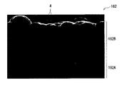
The
図9に示したように、正極161は、正極集電体161Aの一方の面または両面に正極活物質層161Bが設けられたものであり、負極162は、負極集電体162Aの一方の面または両面に負極活物質層162Bが設けられたものである。正極集電体161A、正極活物質層161B、負極集電体162A、負極活物質層162Bおよびセパレータ163の構成は、それぞれ上記した第1の二次電池における正極集電体121A、正極活物質層121B、負極集電体122A、負極活物質層122Bおよびセパレータ123の構成と同様である。セパレータ163には、セパレータ123と同様の電解液が含浸されている。
As shown in FIG. 9, the
この第3の二次電池は、例えば、以下のようにして製造することができる。 This third secondary battery can be manufactured, for example, as follows.
上記した第1の二次電池と同様に、正極161および負極162を、セパレータ163を介して巻回させることにより巻回電極体160を形成したのち、その巻回体160を外装缶151の内部に収容する。次いで、巻回電極体160の上に絶縁板152を配置し、負極リード165を外装缶151に溶接すると共に、正極リード164を正極ピン155の下端に溶接して、外装缶151の開放端部に電池蓋153をレーザ溶接により固定する。最後に、電解液を電解液注入孔159から外装缶151の内部に注入し、セパレータ163に含浸させ、電解液注入孔159を封止部材159Aで塞ぐ。これにより、図9および図10に示した二次電池が完成する。
Similarly to the first secondary battery described above, the
この第3の二次電池によれば、負極162が上記した図1に示した負極10と同様の構成を有しているので、高容量化を図りつつ、サイクル特性を向上させることができる。この第3の二次電池に関する他の効果は、上記した負極10と同様である。
According to the third secondary battery, since the
[4.リチウムイオン二次電池の用途]
次に、上記したリチウムイオン二次電池の適用例について説明する。
[4. Applications of lithium ion secondary batteries]
Next, application examples of the above-described lithium ion secondary battery will be described.
リチウムイオン二次電池の用途は、それを駆動用の電源あるいは電力蓄積用の電力貯蔵源などとして用いることが可能な機械、機器、器具、装置あるいはシステム(複数の機器などの集合体)などであれば、特に限定されない。リチウムイオン二次電池が電源として用いられる場合、それは主電源(優先的に使用される電源)でもよいし、補助電源(主電源に代えて、あるいは主電源から切り換えて使用される電源)でもよい。この主電源の種類は、リチウムイオン二次電池に限られない。 Lithium ion secondary batteries are used in machines, devices, instruments, devices or systems (collections of multiple devices) that can be used as power sources for driving or power storage sources for power storage. If there is, it will not be specifically limited. When a lithium ion secondary battery is used as a power source, it may be a main power source (a power source used preferentially) or an auxiliary power source (a power source used in place of or switched from the main power source). . The type of the main power source is not limited to the lithium ion secondary battery.
リチウムイオン二次電池の用途としては、例えば、以下の用途などが挙げられる。ビデオカメラ、デジタルスチルカメラ、携帯電話機、ノートパソコン、コードレス電話機、ヘッドホンステレオ、携帯用ラジオ、携帯用テレビあるいは携帯用情報端末(PDA:Personal Digital Assistant)などの携帯用電子機器である。電気シェーバなどの携帯用生活器具である。バックアップ電源あるいはメモリーカードなどの記憶用装置である。電動ドリルあるいは電動のこぎりなどの電動工具である。ペースメーカーあるいは補聴器などの医療用電子機器である。電気自動車(ハイブリッド自動車を含む)などの車両である。非常時などに備えて電力を蓄積しておく家庭用バッテリシステムなどの電力貯蔵システムである。もちろん、上記以外の用途でもよい。 Examples of the use of the lithium ion secondary battery include the following uses. It is a portable electronic device such as a video camera, a digital still camera, a mobile phone, a notebook computer, a cordless phone, a headphone stereo, a portable radio, a portable television, or a portable information terminal (PDA: Personal Digital Assistant). It is a portable living device such as an electric shaver. A storage device such as a backup power source or a memory card. An electric power tool such as an electric drill or an electric saw. Medical electronic devices such as pacemakers and hearing aids. Vehicles such as electric vehicles (including hybrid vehicles). It is an electric power storage system such as a home battery system that stores electric power in case of an emergency. Of course, applications other than those described above may be used.
中でも、リチウムイオン二次電池は、電動工具、電気自動車あるいは電力貯蔵システムなどに適用されることが有効である。優れた電池特性(サイクル特性、保存特性および負荷特性など)が要求されるため、本発明のリチウムイオン二次電池を用いることにより、有効に特性向上を図ることができるからである。なお、電動工具は、リチウムイオン二次電池を駆動用の電源として可動部(例えばドリルなど)が可動する工具である。電気自動車は、リチウムイオン二次電池を駆動用電源として作動(走行)する自動車であり、上記したように、リチウムイオン二次電池以外の駆動源も併せて備えた自動車(ハイブリッド自動車など)でもよい。電力貯蔵システムは、リチウムイオン二次電池を電力貯蔵源として用いるシステムである。例えば、家庭用の電力貯蔵システムでは、電力貯蔵源であるリチウムイオン二次電池に電力が蓄積されており、その電力が必要に応じて消費されるため、家庭用電気製品などの各種機器が使用可能になる。 Among these, it is effective that the lithium ion secondary battery is applied to an electric tool, an electric vehicle, an electric power storage system, or the like. This is because excellent battery characteristics (such as cycle characteristics, storage characteristics, and load characteristics) are required, and thus characteristics can be effectively improved by using the lithium ion secondary battery of the present invention. The electric tool is a tool in which a movable part (for example, a drill or the like) is movable using a lithium ion secondary battery as a driving power source. An electric vehicle is a vehicle that operates (runs) using a lithium ion secondary battery as a driving power source. As described above, an electric vehicle (such as a hybrid vehicle) that includes a drive source other than a lithium ion secondary battery may also be used. . The power storage system is a system that uses a lithium ion secondary battery as a power storage source. For example, in a household power storage system, power is stored in a lithium-ion secondary battery, which is a power storage source, and the power is consumed as needed. It becomes possible.
本発明の具体的な実施例について、詳細に説明する。 Specific examples of the present invention will be described in detail.
(実験例1−1)
以下の手順により、図9および図10に示した角型の二次電池を製造した。この際、負極162の容量がリチウムの吸蔵および放出に基づいて表されるリチウムイオン二次電池となるようにした。
(Experimental example 1-1)
The square secondary battery shown in FIGS. 9 and 10 was manufactured by the following procedure. At this time, a lithium ion secondary battery in which the capacity of the
まず、正極161を作製した。すなわち、炭酸リチウム(Li2 CO3 )と炭酸コバルト(CoCO3 )とを0.5:1のモル比で混合したのち、空気中において900℃で5時間焼成することにより、リチウム・コバルト複合酸化物(LiCoO2 )を得た。続いて、正極活物質としてリチウム・コバルト複合酸化物96質量部と、導電剤としてグラファイト1質量部と、結着剤としてポリフッ化ビニリデン3質量部とを混合して正極合剤としたのち、N−メチル−2−ピロリドンに分散させることにより、ペースト状の正極合剤スラリーとした。最後に、帯状のアルミニウム箔(厚さ=15μm)からなる正極集電体161Aの両面に正極合剤スラリーを均一に塗布して乾燥させたのち、ロールプレス機で圧縮成型することにより、正極活物質層161Bを形成した。こののち、正極集電体161Aの一端に、アルミニウム製の正極リード164を溶接して取り付けた。
First, the
次に、負極162を作製した。具体的には、まず、電解銅箔からなる負極集電体162A(厚さ=20μm,十点平均粗さRz=4.0μm)を準備した。そののち、電子ビーム蒸着法を用いて負極集電体162Aの両面に負極活物質を複数回に亘って堆積させ、第1の層1および第2の層2を交互に積層することで、全体の厚さが8μmの負極活物質層162Bを得た。ここでは単結晶珪素からなる蒸発源と、金属元素Xとしてのニッケルからなる蒸着源とを用い、各々の蒸発源からの蒸発レートを変化させることで所定の組成を有する第1の層1および第2の層1を交互に蒸着させた。詳細には、表1に示したように、第1の層1における珪素含有率Aについては90原子数%、第2の層2における珪素含有率Bについては89原子数%となるように、上記の蒸発レートを調整した。また、蒸着処理の時間を調整することにより、第1の層1の厚さCおよび第2の層2の厚さDは、それぞれ0.4μmおよび0.2μmとなるように作製した。負極活物質層162Bを形成したのち、負極集電体162Aの一端に、ニッケル製の負極リード165を溶接して取り付けた。
Next, the
このようにして得られた負極162の断面を拡大して観察したところ、例えば図11に示したように、負極集電体162Aの表面の突起部を基点としてその表面に直交する方向へ延在する複数の負極活物質粒子4が確認された。さらに、各負極活物質粒子4は、互いに珪素含有率の異なる第1および第2の層1,2が交互に積層されたものであることも確認された。なお、図11は、クロスセクションポリッシャーにより研磨して得た負極162の断面を、走査型電子顕微鏡 (SEM;Scanning Electron Microscope)によって観察した画像(SEM画像)である。このようなSEM画像に基づき、厚さCおよび厚さDについて測定したところ、それぞれ平均で0.4μmおよび0.2μmであることが確認できた。さらに、第1および第2の層1,2における各々の組成(珪素含有率)を、エネルギー分散型X線分析装置(EDX:Energy Dispersive X-ray spectrometer)による微小領域元素分析により測定したところ、珪素含有率Aが90原子数%、珪素含有率Bが89原子数%であることが確認できた。但し、図11は、電子ビーム蒸着法を用いて作製した本発明の負極の一例を表すものであり、具体的には実験例1−4(後出)の負極のSEM画像である。
When the cross section of the
続いて、23μm厚の微孔性ポリエチレンフィルムよりなるセパレータ163を用意し、正極161と,セパレータ163と、負極162と、セパレータ163とを順に積層して積層体を形成したのち、この積層体を渦巻状に複数回巻回することで巻回電極体160を作製した。得られた巻回電極体160は、偏平な形状に成形した。
Subsequently, a
次に、偏平形状に成型された巻回電極体160を外装缶151の内部に収容したのち、巻回電極体160の上に絶縁板152を配置し、負極リード165を外装缶151に溶接すると共に、正極リード144を正極ピン155の下端に溶接して、外装缶151の開放端部に電池蓋153をレーザ溶接により固定した。そののち、電解液注入孔159から外装缶151の内部に電解液を注入した。電解液には、炭酸エチレン(EC)50重量%と炭酸ジエチル(DEC)50重量%とを混合した溶媒に、電解質塩としてLiPF6 を1mol/kgの濃度で溶解させたものを用いた。最後に、電解液注入孔159を封止部材159Aで塞ぐことにより、角型の二次電池を得た。
なお、電池容量は800mAhとなるようにした。また、負極活物質の容量利用率(負極利用率)を50%として設計した。ここでいう負極利用率とは、満充電状態における負極162の単位面積あたりのリチウムの吸蔵量をA、負極162の単位面積あたりの電気化学的に吸蔵可能なリチウムの量をBとしたとき、A/B×100(%)で表される数値を意味する。
Next, after the
The battery capacity was set to 800 mAh. Moreover, the capacity utilization factor (negative electrode utilization factor) of the negative electrode active material was designed to be 50%. The negative electrode utilization rate here means that the amount of lithium occluded per unit area of the
(実験例1−2〜1−8)
負極活物質層162Bを形成するにあたり、珪素含有率Bをそれぞれ表1に示したように変更した点を除き、他は実験例1−1と同様にして実験例1−2〜1−8の二次電池を作製した。
(Experimental Examples 1-2 to 1-8)
In forming the negative electrode
(実験例1−9,1−10)
負極活物質層162Bを形成するにあたり、均質な負極活物質の組成とした(すなわち、珪素含有率A,Bが互いに等しくなるようにした)ことを除き、他は実験例1−1と同様にして実験例1−9,1−10の二次電池を作製した。なお、実験例1−9では負極活物質として珪素のみを含むようにし、実験例1−10では負極活物質として珪素およびニッケルを含み、かつ、珪素含有率A,Bが90原子数%となるようにした。
(Experimental examples 1-9, 1-10)
The negative electrode
このようにして作製した実験例1−1〜1−10の二次電池についてサイクル特性を調べた。その結果を表1に示す。さらに、実験例1−2〜1−10の二次電池についても、実験例1−1と同様にして珪素含有率A,Bならびに厚さC,Dを測定し、確認をおこなった。それらの結果についても併せて表1に示す。なお、以下で説明する他の実験例の二次電池についても同様の方法により珪素含有率A,Bならびに厚さC,Dを測定し、確認をおこなったが、その旨の説明は省略する。 The cycle characteristics of the secondary batteries of Experimental Examples 1-1 to 1-10 produced in this manner were examined. The results are shown in Table 1. Further, for the secondary batteries of Experimental Examples 1-2 to 1-10, the silicon contents A and B and the thicknesses C and D were measured and confirmed in the same manner as in Experimental Example 1-1. The results are also shown in Table 1. In addition, the secondary batteries of other experimental examples described below were also confirmed by measuring and confirming the silicon contents A and B and the thicknesses C and D by the same method, but the description to that effect is omitted.
サイクル特性を調べる際には、以下の手順でサイクル試験を行うことにより、放電容量維持率を求めた。まず、電池状態を安定化させるために25℃の雰囲気中において1サイクル充放電させたのち、再び充放電させることにより、2サイクル目の放電容量を測定した。続いて、同雰囲気中において98サイクル充放電させることにより、100サイクル目の放電容量を測定した。最後に、放電容量維持率(%)=(100サイクル目の放電容量/2サイクル目の放電容量)×100を算出した。この際、最初の1サイクルについては、まず、0.3mA/cm2 の定電流密度で電池電圧が4.25Vに到達するまで定電流充電したのち、引き続き4.25Vの定電圧で電流密度が0.1mA/cm2 に到達するまで定電圧充電し、さらに、0.1mA/cm2 の定電流密度で電池電圧が2.7Vに到達するまで定電流放電した。また、2サイクル目以降の1サイクルについては、まず、3mA/cm2 の定電流密度で電池電圧が4.2Vに到達するまで定電流充電したのち、引き続き4.2Vの定電圧で電流密度が0.1mA/cm2 に到達するまで定電圧充電し、さらに、3mA/cm2 の定電流密度で電池電圧が2.7Vに到達するまで定電流放電した。 When examining the cycle characteristics, the discharge capacity retention rate was determined by performing a cycle test according to the following procedure. First, in order to stabilize the battery state, charge / discharge was performed for 1 cycle in an atmosphere at 25 ° C., and then charge / discharge was performed again to measure the discharge capacity at the second cycle. Subsequently, the discharge capacity at the 100th cycle was measured by charging and discharging 98 cycles in the same atmosphere. Finally, discharge capacity retention ratio (%) = (discharge capacity at the 100th cycle / discharge capacity at the second cycle) × 100 was calculated. At this time, for the first cycle, first, constant current charging was performed until the battery voltage reached 4.25 V at a constant current density of 0.3 mA / cm 2 , and then the current density was continuously maintained at a constant voltage of 4.25 V. The battery was charged at a constant voltage until reaching 0.1 mA / cm 2 , and further discharged at a constant current density of 0.1 mA / cm 2 until the battery voltage reached 2.7V. In addition, for one cycle after the second cycle, first, constant current charging is performed until the battery voltage reaches 4.2 V at a constant current density of 3 mA / cm 2 , and then the current density continues at a constant voltage of 4.2 V. The battery was charged at a constant voltage until reaching 0.1 mA / cm 2 and further discharged at a constant current density of 3 mA / cm 2 until the battery voltage reached 2.7 V.

負極活物質として珪素のみを含む実験例1−9に対し、ニッケルを添加するようにした実験例1−1〜1−8,1−10では、放電容量維持率の向上が認められた。特に、組成比A/Bが条件式(1)を満足する場合(実験例1−2〜1−7)には、それ以外の場合(実験例1−1,1−8〜1−10)と比較して放電容量維持率の大きな向上が認められた。この理由としては、まず、組成比A/Bが小さすぎると応力緩和効果が小さいので、放電容量維持率への寄与が明確に認められるまでに至らないと考えられる。一方、組成比A/Bが大きすぎると第1の層と第2の層との間で充放電時の膨張収縮率の差が大きくなりすぎてしまい、両者の界面において応力が発生し、放電容量維持率の向上を妨げると考えられる。 In Experimental Examples 1-1 to 1-8 and 1-10 in which nickel was added to Experimental Example 1-9 containing only silicon as the negative electrode active material, an improvement in the discharge capacity retention rate was observed. In particular, when the composition ratio A / B satisfies the conditional expression (1) (Experimental Examples 1-2 to 1-7), the other cases (Experimental Examples 1-1, 1-8 to 1-10) As a result, a significant improvement in the discharge capacity retention rate was observed. As a reason for this, first, if the composition ratio A / B is too small, the stress relaxation effect is small, so that it is considered that the contribution to the discharge capacity retention rate is not clearly recognized. On the other hand, if the composition ratio A / B is too large, the difference in expansion / contraction rate during charging / discharging between the first layer and the second layer becomes too large, and stress is generated at the interface between the two. This is considered to hinder the improvement of the capacity maintenance rate.
(実験例2−1〜2−9)
次に、第1の層1における珪素含有率Aについては70原子数%に固定し、かつ、第2の層2における珪素含有率Bを表2に示したように各々変化させたことを除き、他は実験例1−1と同様にして実験例2−1〜2−9の二次電池を作製した。これらの実験例2−1〜2−9についてもサイクル特性(放電容量維持率)を調べたところ、表2に表した結果が得られた。
(Experimental examples 2-1 to 2-9)
Next, the silicon content A in the
表2に示したように、珪素含有率Aを70原子数%とした場合においても、珪素含有率Bとの関係を規定する条件式(1)を満足すると、放電容量維持率の大きな向上が得られることがわかった。 As shown in Table 2, even when the silicon content A is 70 atomic%, if the conditional expression (1) that defines the relationship with the silicon content B is satisfied, the discharge capacity maintenance rate is greatly improved. It turns out that it is obtained.
(実験例3−1〜3−10)
負極活物質層162Bを形成するにあたり、厚さCを表3に表したように変化させると共に厚さDを0.4μmとし、かつ、第1および第2の層を2層ずつ交互に積層するようにした。これらの点を除き、他は実験例1−3と同様にして実験例3−1〜3−10の二次電池を作製した。これらの実験例3−1〜3−10についてもサイクル特性(放電容量維持率)を調べたところ、表3に示した結果が得られた。
(Experimental examples 3-1 to 3-10)
In forming the negative electrode
表3に示したように、組成比C/Dが条件式(2)を満足する場合(実験例3−2〜3−9)には、それ以外の場合(実験例3−1,3−10)と比較して放電容量維持率の大きな向上が認められた。 As shown in Table 3, when the composition ratio C / D satisfies the conditional expression (2) (Experimental examples 3-2 to 3-9), the other cases (Experimental examples 3-1 and 3- Compared with 10), a significant improvement in the discharge capacity retention rate was observed.
(実験例4−1〜4−10)
次に、厚さCを0.4μmとすると共に厚さDを表4に表したように変化させたことを除き、他は実験例3−1と同様にして実験例4−1〜4−10の二次電池を作製した。これらの実験例4−1〜4−10についてもサイクル特性(放電容量維持率)を調べたところ、表4に示した結果が得られた。
(Experimental examples 4-1 to 4-10)
Next, experimental examples 4-1 to 4- are performed in the same manner as in experimental example 3-1, except that the thickness C is set to 0.4 μm and the thickness D is changed as shown in Table 4. Ten secondary batteries were produced. When the cycle characteristics (discharge capacity retention ratio) of these experimental examples 4-1 to 4-10 were also examined, the results shown in Table 4 were obtained.
表4に示したように、やはり組成比C/Dが条件式(2)を満足する場合(実験例4−2〜4−9)には、それ以外の場合(実験例4−1,4−10)と比較して放電容量維持率の大きな向上が認められた。 As shown in Table 4, when the composition ratio C / D also satisfies the conditional expression (2) (Experimental examples 4-2 to 4-9), the other cases (Experimental examples 4-1 and 4). As compared with -10), a significant improvement in the discharge capacity retention rate was observed.
(実験例5−1〜5−7)
次に、負極活物質としての金属元素Xを表5に表したように変化させたことを除き、他は実験例1−3と同様にして実験例5−1〜5−7の二次電池を作製した。
(Experimental Examples 5-1 to 5-7)
Next, the secondary batteries of Experimental Examples 5-1 to 5-7 were the same as Experimental Example 1-3 except that the metal element X as the negative electrode active material was changed as shown in Table 5. Was made.
(実験例5−8〜5−14)
負極活物質層162Bを形成するにあたり、均質な負極活物質の組成とした(すなわち、珪素含有率A,Bが互いに等しくなるようにした)ことを除き、他は実験例5−1〜5−7とそれぞれ同様にして実験例5−8〜5−14の二次電池を作製した。なお、実験例5−8〜5−14では珪素含有率A,Bが90原子数%となるようにした。
(Experimental Examples 5-8 to 5-14)
Except that the negative electrode
これらの実験例5−1〜5−14についてもサイクル特性(放電容量維持率)を調べたところ、表5に示した結果が得られた。 When the cycle characteristics (discharge capacity retention ratio) of these experimental examples 5-1 to 5-14 were also examined, the results shown in Table 5 were obtained.
表5に示したように、組成比A/Bが条件式(1)を満足する場合(実験例5−1〜5−7)には、それ以外の場合(実験例5−8〜1−14)とそれぞれ比較して放電容量維持率の大きな向上が認められた。すなわち、金属元素Xとして、ニッケルの代わりにコバルト,鉄,マンガン,クロム,チタン,アルミニウム,マグネシウムおよびモリブデンを用いた場合においても、ニッケルを用いた場合と同様の傾向が見られることが確認できた。なお、本実験例では、単一種の金属元素Xを添加するようにしたが、複数種の金属元素Xを用いて珪素と共に負極活物質を構成するようにした場合においても、同様の効果が得られることを確認した。 As shown in Table 5, when the composition ratio A / B satisfies the conditional expression (1) (Experimental Examples 5-1 to 5-7), the other cases (Experimental Examples 5-8 to 1- 1) Compared with 14), a significant improvement in the discharge capacity retention rate was observed. That is, even when cobalt, iron, manganese, chromium, titanium, aluminum, magnesium and molybdenum were used as the metal element X instead of nickel, it was confirmed that the same tendency as when nickel was used was observed. . In this experimental example, a single type of metal element X is added, but the same effect can be obtained even when a negative electrode active material is configured with silicon using a plurality of types of metal element X. It was confirmed that
(実験例6−1〜6−4)
負極集電体162Aの表面粗さ(Rz値)を、表6に表したように1.0μm〜7.5μmの範囲で変化させたことを除き、他は実験例1−3と同様にして実験例6−1〜6−4の二次電池を作製した。
(Experimental examples 6-1 to 6-4)
Except that the surface roughness (Rz value) of the negative electrode
これらの実験例6−1〜6−4の二次電池についてサイクル特性を調べたところ、表6に示した結果が得られた。なお、表6には、実験例1−3の結果も併せて示した。 When the cycle characteristics of the secondary batteries of Examples 6-1 to 6-4 were examined, the results shown in Table 6 were obtained. Table 6 also shows the results of Experimental Example 1-3.
表6に示したように、負極集電体72Aの表面粗さ(Rz値)が1.5μm以上6.5μm以下の場合に、より高い放電容量維持率が得られることがわかった。 As shown in Table 6, it was found that when the surface roughness (Rz value) of the negative electrode current collector 72A was 1.5 μm or more and 6.5 μm or less, a higher discharge capacity retention rate was obtained.
(実験例7−1〜7−4)
負極利用率を、表7に表したように10%〜90%の範囲で変化させたことを除き、他は実験例1−3と同様にして実験例7−1〜7−4の二次電池を作製した。なお、負極利用率については、正極活物質層161Bの単位面積あたりの塗布量を変化させることにより調整した。
(Experimental examples 7-1 to 7-4)
Except that the negative electrode utilization rate was changed in the range of 10% to 90% as shown in Table 7, the others were the same as in Experimental Example 1-3, and the secondary of Experimental Examples 7-1 to 7-4. A battery was produced. In addition, about the negative electrode utilization factor, it adjusted by changing the coating amount per unit area of the positive electrode active material layer 161B.
これらの実験例7−1〜7−4の二次電池についてサイクル特性を調べたところ、表7に示した結果が得られた。なお、表7には、実験例1−3の結果も併せて示した。 When the cycle characteristics of the secondary batteries of Experimental Examples 7-1 to 7-4 were examined, the results shown in Table 7 were obtained. Table 7 also shows the results of Experimental Example 1-3.
表7に示したように、負極利用率が20%以上80%以下の場合に、より高い放電容量維持率が得られることがわかった。 As shown in Table 7, it was found that a higher discharge capacity retention rate was obtained when the negative electrode utilization rate was 20% or more and 80% or less.
(実験例8−1〜8−4)
正極活物質としてのLiCoO2 の一部または全部をLiNiO2に置き換えたものを用いたことを除き、他は実験例1−3と同様にして実験例8−1〜8−4の二次電池を作製した。
(Experimental examples 8-1 to 8-4)
The secondary batteries of Experimental Examples 8-1 to 8-4 were the same as Experimental Example 1-3 except that a part or all of LiCoO 2 as the positive electrode active material was replaced with LiNiO 2. Was made.
表8に示したように、正極活物質中におけるLiNiO2の含有率が増加するほど高い放電容量維持率が得られることがわかった。すなわち、より良好なサイクル特性を得るには、コバルトよりもニッケルを多く含む正極活物質を用いることが好ましいと推測される。 As shown in Table 8, it was found that a higher discharge capacity retention rate was obtained as the content of LiNiO 2 in the positive electrode active material increased. That is, in order to obtain better cycle characteristics, it is presumed that it is preferable to use a positive electrode active material containing more nickel than cobalt.
(実験例9−1)
溶媒としてECおよびDECに加えて4−フルオロ−1,3−ジオキソラン−2−オン(FEC)を用い、溶媒の組成(EC:DEC:FEC)を重量比で40:50:10に変更したことを除き、他は実験例1−3と同様にして実験例9−1の二次電池を作製した。
(Experimental example 9-1)
Using 4-fluoro-1,3-dioxolan-2-one (FEC) in addition to EC and DEC as the solvent, and changing the solvent composition (EC: DEC: FEC) to 40:50:10 by weight Otherwise, the secondary battery of Experimental Example 9-1 was fabricated in the same manner as Experimental Example 1-3.
(実験例9−2)
溶媒としてECおよびDECに加えて4,5−ジフルオロ−1,3−ジオキソラン−2−オン(DFEC)を用い、溶媒の組成(EC:DEC:DFEC)を重量比で40:50:10に変更したことを除き、他は実験例1−3と同様にして実験例9−2の二次電池を作製した。
(Experimental example 9-2)
In addition to EC and DEC, 4,5-difluoro-1,3-dioxolan-2-one (DFEC) was used as a solvent, and the composition of the solvent (EC: DEC: DFEC) was changed to 40:50:10 by weight ratio. Otherwise, the secondary battery of Experimental Example 9-2 was fabricated in the same manner as Experimental Example 1-3.
(実験例9−3,9−4)
電解液に添加剤として、酸無水物であるスルホ安息香酸無水物(SBAH:実験例9−3)あるいはスルホプロピオン酸無水物(SPAH:実験例9−4)を加えたことを除き、他は実験例1−3と同様にして二次電池を作製した。この際、電解液中におけるSBAHおよびSPAHの含有量を1重量%とした。この「1重量%」は、溶媒全体を100重量%としたとき、1重量%に相当する分だけSBAHまたはSPAHを添加したという意味である。
(Experimental examples 9-3, 9-4)
Except that the acid anhydride sulfobenzoic anhydride (SBAH: Experimental Example 9-3) or sulfopropionic anhydride (SPAH: Experimental Example 9-4) was added as an additive to the electrolyte. A secondary battery was fabricated in the same manner as in Experimental Example 1-3. At this time, the contents of SBAH and SPAH in the electrolytic solution were 1% by weight. This “1 wt%” means that SBAH or SPAH is added in an amount corresponding to 1 wt% when the entire solvent is 100 wt%.
(実験例9−5)
電解液に、溶媒としてスルトンである1,3−プロペンスルトン(PRS)を加えたことを除き、他は実験例1−3と同様にして実験例9−5の二次電池を作製した。この際、電解液中におけるPRSの濃度を1重量%とした。この「1重量%」は、PRSを除く溶媒全体を100重量%としたとき、1重量%に相当する分だけPRSを添加したという意味である。
(Experimental Example 9-5)
A secondary battery of Experimental Example 9-5 was fabricated in the same manner as Experimental Example 1-3, except that 1,3-propene sultone (PRS), which is sultone, was added as a solvent to the electrolytic solution. At this time, the concentration of PRS in the electrolytic solution was set to 1% by weight. This “1 wt%” means that PRS is added by an amount corresponding to 1 wt% when the entire solvent excluding PRS is 100 wt%.
(実験例9−6,9−7)
電解液に添加剤として、炭酸ビニレン(VC)あるいは炭酸ビニルエチレン(VEC)を加えたことを除き、他は実験例1−3と同様にして二次電池を作製した。この際、電解液中におけるVCおよびVECの含有量を1重量%とした。この「1重量%」は、溶媒全体を100重量%としたとき、1重量%に相当する分だけVCまたはVECを添加したという意味である。
(Experimental examples 9-6, 9-7)
A secondary battery was fabricated in the same manner as in Experimental Example 1-3, except that vinylene carbonate (VC) or vinyl ethylene carbonate (VEC) was added as an additive to the electrolytic solution. At this time, the contents of VC and VEC in the electrolyte were 1% by weight. This “1 wt%” means that VC or VEC is added in an amount corresponding to 1 wt% when the entire solvent is 100 wt%.
(実験例9−8)
電解質塩として、四フッ化ホウ酸リチウム(LiBF4 )を溶媒に対して0.1mol/kgの割合でさらに加えたことを除き、他は実験例1−3と同様にして実験例9−8の二次電池を作製した。
(Experimental Example 9-8)
Experimental Example 9-8 was the same as Experimental Example 1-3, except that lithium tetrafluoroborate (LiBF 4 ) was further added as an electrolyte salt at a rate of 0.1 mol / kg with respect to the solvent. A secondary battery was prepared.
これらの実験例9−1〜9−8の二次電池についてサイクル特性(放電容量維持率)を調べたところ、表9に表した結果が得られた。 When the cycle characteristics (discharge capacity retention ratio) of the secondary batteries of Examples 9-1 to 9-8 were examined, the results shown in Table 9 were obtained.
表9に示したように、溶媒としてFECやDFECを加えた場合には、放電容量維持率が、より向上することがわかった。また、電解液中に添加剤としてSBAH,SPAH,PRS,VCおよびVECをそれぞれ加えた場合(実施例9−3〜9−7)、あるいは電解質塩としてLiBF4 をさらに加えた場合(実施例9−8)においては、それらを加えない場合(実施例1−3)よりもやや高い放電容量維持率が得られた。 As shown in Table 9, it was found that when FEC or DFEC was added as a solvent, the discharge capacity retention rate was further improved. Further, when SBAH, SPAH, PRS, VC and VEC are respectively added as additives to the electrolytic solution (Examples 9-3 to 9-7), or when LiBF 4 is further added as an electrolyte salt (Example 9) In −8), a slightly higher discharge capacity retention rate was obtained than in the case where they were not added (Example 1-3).
(実験例10−1)
以下の手順により、角型の二次電池に代えて、図6〜図8に示したラミネートフィルム型の二次電池を作製した。この際、負極134の容量がリチウムの吸蔵および放出に基づいて表されるリチウムイオン二次電池となるようにした。
(Experimental example 10-1)
The laminated film type secondary battery shown in FIGS. 6 to 8 was produced by the following procedure instead of the square type secondary battery. At this time, a lithium ion secondary battery in which the capacity of the
最初に、正極133を作製した。まず、実験例1−3と同様にして作製した正極合剤スラリーを、帯状のアルミニウム箔(厚さ=15μm)からなる正極集電体133Aの両面に正極合剤スラリーを均一に塗布して乾燥させたのち、ロールプレス機で圧縮成型することにより、正極活物質層133Bを形成した。
First, the
次に、負極134を作製した。まず、負極集電体134Aとして電解銅箔(厚さ=20μm,十点平均粗さRz=4.0μm)を準備してチャンバ内に載置した。次に、単結晶珪素からなる蒸発源およびニッケルからなる蒸着源を用い、電子ビーム蒸着法を用いて負極集電体134Aの両面に負極活物質を複数回に亘って堆積させ、第1の層1および第2の層2を交互に積層することで、全体の厚さが8μmの負極活物質層134Bを得た。
Next, the
次に、正極133および負極134と共に、実験例1−3と同様の電解液を用いて二次電池を組み立てた。ここでは、正極集電体133Aの一端にアルミニウム製の正極リード131を溶接すると共に、負極集電体134Aの一端にニッケル製の負極リード132を溶接した。続いて、正極133と、23μm厚の微孔性ポリエチレンフィルムよりなるセパレータ135と、負極134と、セパレータ135とをこの順に積層してから長手方向に巻回させたのち、粘着テープからなる保護テープ137で巻き終わり部分を固定して、巻回電極体130の前駆体である巻回体を形成した。続いて、外側から、ナイロンフィルム(厚さ=30μm)とアルミニウム箔(厚さ=40μm)と無延伸ポリプロピレンフィルム(厚さ=30μm)とが積層された3層構造のラミネートフィルム(総厚=100μm)からなる外装部材140の間に上記の巻回体を挟み込んだのち、一辺を除く外縁部同士を熱融着して、袋状の外装部材140の内部に巻回体を収納した。続いて、外装部材140の開口部から電解液を注入してセパレータ135に含浸させて巻回電極体130を作製した。最後に、真空雰囲気中において外装部材140の開口部を熱融着して封止することにより、ラミネートフィルム型の二次電池が完成した。なお、二次電池を製造する際には、正極活物質層133Bの厚さを調節することにより、満充電時において負極134にリチウム金属が析出しないようにした。
Next, a secondary battery was assembled using the electrolyte solution similar to Experimental Example 1-3 together with the
(実験例10−2)
鉄製の電池缶111に代えて、アルミニウム製の電池缶111を用いたことを除き、他は実験例1−3と同様にして実験例10−2の二次電池を作製した。
(Experimental example 10-2)
A secondary battery of Experimental Example 10-2 was fabricated in the same manner as Experimental Example 1-3 except that the aluminum battery can 111 was used instead of the iron battery can 111.
これらの実験例10−1,10−2の二次電池についてサイクル特性(放電容量維持率)を調べたところ、表10に示した結果が得られた。なお、表10には、実験例1−3の結果も併せて示した。 When the cycle characteristics (discharge capacity retention ratio) of the secondary batteries of Examples 10-1 and 10-2 were examined, the results shown in Table 10 were obtained. In Table 10, the results of Experimental Example 1-3 are also shown.
表10に示したように、角型の二次電池(実験例10−2,1−3)では、ラミネートフィルム型の二次電池(実験例10−1)よりも高い放電容量維持率が得られた。特に、外装部材(電池缶111)が鉄製である実験例1−3においてアルミニウム製である実験例10−2よりも高い放電容量維持率が得られた。これらのことから、サイクル特性をより向上させるためには、電池構造をラミネートフィルム型よりも角型とすればよいことが確認されたと共に、そのサイクル特性をさらに向上させるためには、鉄製の外装部材を用いればよいことが確認された。なお、ここでは具体的な実験例を挙げて説明しないが、外装部材が金属材料からなる角型の二次電池においてラミネートフィルム型の二次電池よりもサイクル特性が向上したことから、外装部材が金属材料からなる円筒型やコイン型の二次電池においても同様の結果が得られることは明らかである。 As shown in Table 10, the square secondary batteries (Experimental Examples 10-2 and 1-3) have a higher discharge capacity retention rate than the laminate film secondary battery (Experimental Example 10-1). It was. In particular, in Experimental Example 1-3 in which the exterior member (battery can 111) was made of iron, a higher discharge capacity retention rate was obtained than in Experimental Example 10-2 made of aluminum. From these, in order to further improve the cycle characteristics, it was confirmed that the battery structure should be square rather than the laminate film type, and in order to further improve the cycle characteristics, an iron exterior It was confirmed that a member should be used. In addition, although it does not explain by giving a specific experimental example here, the cycle member improved in the square type secondary battery in which the exterior member is made of a metal material as compared with the laminate film type secondary battery. It is clear that similar results can be obtained with a cylindrical or coin-type secondary battery made of a metal material.
以上の各実験例の結果から、本発明のリチウムイオン二次電池によれば、積層構造を有する負極活物質層の構造破壊が抑制されると共に、積層構造における各層間の密着性が向上するので、サイクル特性に優れることがわかった。 From the results of the above experimental examples, according to the lithium ion secondary battery of the present invention, structural breakdown of the negative electrode active material layer having a laminated structure is suppressed, and adhesion between the layers in the laminated structure is improved. It was found that the cycle characteristics were excellent.
以上、実施の形態および実施例を挙げて本発明を説明したが、本発明はそれらで説明した態様に限定されず、種々の変形が可能である。例えば、負極の容量がリチウムイオンの吸蔵放出により表される場合について説明したが、必ずしもこれに限られない。本発明は、負極の容量がリチウムイオンの吸蔵放出による容量とリチウム金属の析出溶解による容量とを含み、かつ、それらの容量の和により表される場合についても適用可能である。この場合には、負極活物質としてリチウムイオンを吸蔵放出可能な負極材料が用いられると共に、負極材料の充電可能な容量が正極の放電容量よりも小さくなるように設定される。 Although the present invention has been described with reference to the embodiments and examples, the present invention is not limited to the embodiments described above, and various modifications can be made. For example, although the case where the capacity of the negative electrode is expressed by occlusion / release of lithium ions has been described, the present invention is not necessarily limited thereto. The present invention is also applicable to the case where the capacity of the negative electrode includes a capacity due to insertion and extraction of lithium ions and a capacity due to precipitation dissolution of lithium metal, and is expressed by the sum of these capacities. In this case, a negative electrode material capable of inserting and extracting lithium ions is used as the negative electrode active material, and the chargeable capacity of the negative electrode material is set to be smaller than the discharge capacity of the positive electrode.
また、上記した実施の形態および実施例では、電池構造が円筒型、ラミネートフィルム型あるいは角型である場合や、電池素子が巻回構造を有する場合を例に挙げて説明したが、必ずしもこれに限られない。本発明の二次電池は、電池構造がコイン型あるいはボタン型などである場合や、電池素子が積層構造などを有する場合についても、同様に適用可能である。 Further, in the above-described embodiments and examples, the case where the battery structure is a cylindrical type, the laminate film type or the square type, or the case where the battery element has a winding structure has been described as an example. Not limited. The secondary battery of the present invention can be similarly applied to a case where the battery structure is a coin type or a button type or a case where the battery element has a laminated structure or the like.
1…第1の層、2…第2の層、3…挿入層、4…負極活物質粒子、10,10C…負極、101,122A,134A,162A…負極集電体、102,102A,122B,134B,162B…負極活物質層、111…電池缶、112,113…絶縁板、114…電池蓋、115…安全弁機構、115A…ディスク板、116…熱感抵抗素子、117…ガスケット、120,130,160…巻回電極体、121,133,161…正極、121A,133A,161A…正極集電体、121B,133B,161B…正極活物質層、122,134,162…負極、123,135,163…セパレータ、124…センターピン、125,131,164…正極リード、126,132,165…負極リード、136…電解質、137…保護テープ、140…外装部材、141…密着フィルム、151…外装缶、152…絶縁板、153…電池蓋、154…端子板、155…正極ピン、156…絶縁ケース、157…ガスケット、158…開裂弁、159…電解液注入孔、159A…封止部材。
DESCRIPTION OF
Claims (20)
リチウムイオン二次電池用負極。
1.02≦A/B≦50 ……(1)
但し、
A:第1の層における負極活物質中の珪素含有率
B:第2の層における負極活物質中の珪素含有率 The negative electrode current collector has a negative electrode active material layer formed by alternately laminating first and second layers each containing silicon (Si) and a metal element as a negative electrode active material, and the conditional expression (1 ) Satisfying negative electrode for lithium ion secondary battery.
1.02 ≦ A / B ≦ 50 (1)
However,
A: Silicon content in negative electrode active material in first layer B: Silicon content in negative electrode active material in second layer
請求項1記載のリチウムイオン二次電池用負極。 The metal elements are nickel (Ni), cobalt (Co), iron (Fe), manganese (Mn), chromium (Cr), titanium (Ti), aluminum (Al), magnesium (Mg) and molybdenum (Mo). The negative electrode for a lithium ion secondary battery according to claim 1, which is at least one of them.
請求項1記載のリチウムイオン二次電池用負極。 2. The negative electrode for a lithium ion secondary battery according to claim 1, wherein the silicon content in the negative electrode active material in the second layer is from 1.8 atomic% to 88 atomic%.
0.1≦C/D≦40 ……(2)
但し、
C:第1の層の厚さ
D:第2の層の厚さ Furthermore, the negative electrode for lithium ion secondary batteries of Claim 1 which satisfies the following conditional expression (2).
0.1 ≦ C / D ≦ 40 (2)
However,
C: thickness of the first layer D: thickness of the second layer
請求項1記載のリチウムイオン二次電池用負極。 The negative electrode for a lithium ion secondary battery according to claim 1, wherein the negative electrode active material layer includes a plurality of particles, and each of the particles has a laminated structure of the first layer and the second layer.
請求項1記載のリチウムイオン二次電池用負極。 2. The negative electrode for a lithium ion secondary battery according to claim 1, wherein at least a part of the negative electrode active material layer is alloyed with the negative electrode current collector at an interface with the negative electrode current collector.
前記負極は、
負極集電体上に、珪素(Si)および金属元素を負極活物質として各々含有する第1および第2の層が交互に積層されてなる負極活物質層を有し、かつ、条件式(1)を満足する
リチウムイオン二次電池。
1.02≦A/B≦50 ……(1)
但し、
A:第1の層における負極活物質中の珪素含有率
B:第2の層における負極活物質中の珪素含有率 An electrolyte is provided with a positive electrode and a negative electrode,
The negative electrode is
The negative electrode current collector has a negative electrode active material layer formed by alternately laminating first and second layers each containing silicon (Si) and a metal element as a negative electrode active material, and the conditional expression (1 ) Lithium ion secondary battery.
1.02 ≦ A / B ≦ 50 (1)
However,
A: Silicon content in negative electrode active material in first layer B: Silicon content in negative electrode active material in second layer
請求項8記載のリチウムイオン二次電池。 The metal elements are nickel (Ni), cobalt (Co), iron (Fe), manganese (Mn), chromium (Cr), titanium (Ti), aluminum (Al), magnesium (Mg) and molybdenum (Mo). The lithium ion secondary battery according to claim 8, which is at least one of them.
請求項8記載のリチウムイオン二次電池。 The lithium ion secondary battery according to claim 8, wherein the silicon content in the negative electrode active material in the second layer is from 1.8 atomic% to 88 atomic%.
0.1≦C/D≦40 ……(2)
但し、
C:第1の層の厚さ
D:第2の層の厚さ Furthermore, the lithium ion secondary battery of Claim 8 which satisfies the following conditional expression (2).
0.1 ≦ C / D ≦ 40 (2)
However,
C: thickness of the first layer D: thickness of the second layer
請求項8記載のリチウムイオン二次電池。 The lithium ion secondary battery according to claim 8, wherein the negative electrode active material layer includes a plurality of particles, and each of the particles has a stacked structure of the first layer and the second layer.
請求項8記載のリチウムイオン二次電池。 When the electrolyte is a solvent, 4-fluoro-1,3-dioxolan-2-one (FEC), 4,5-difluoro-1,3-dioxolan-2-one (DEFC), vinylene carbonate (VC), and vinyl carbonate The lithium ion secondary battery according to claim 8, comprising at least one of ethylene (VEC).
前記負極は、
負極集電体上に、珪素(Si)および金属元素を負極活物質として各々含有する第1および第2の層が交互に積層されてなる負極活物質層を有し、かつ、条件式(1)を満足する
電動工具。
1.02≦A/B≦50 ……(1)
但し、
A:第1の層における負極活物質中の珪素含有率
B:第2の層における負極活物質中の珪素含有率 A power tool that operates using a lithium ion secondary battery including an electrolyte together with a positive electrode and a negative electrode as a power source,
The negative electrode is
The negative electrode current collector has a negative electrode active material layer formed by alternately laminating first and second layers each containing silicon (Si) and a metal element as a negative electrode active material, and the conditional expression (1 Electric tool that satisfies).
1.02 ≦ A / B ≦ 50 (1)
However,
A: Silicon content in negative electrode active material in first layer B: Silicon content in negative electrode active material in second layer
前記負極は、
負極集電体上に、珪素(Si)および金属元素を負極活物質として各々含有する第1および第2の層が交互に積層されてなる負極活物質層を有し、かつ、条件式(1)を満足する
電気自動車。
1.02≦A/B≦50 ……(1)
但し、
A:第1の層における負極活物質中の珪素含有率
B:第2の層における負極活物質中の珪素含有率 An electric vehicle that operates using a lithium ion secondary battery including an electrolyte solution together with a positive electrode and a negative electrode as a power source,
The negative electrode is
The negative electrode current collector has a negative electrode active material layer formed by alternately laminating first and second layers each containing silicon (Si) and a metal element as a negative electrode active material, and the conditional expression (1 Electric vehicle that satisfies).
1.02 ≦ A / B ≦ 50 (1)
However,
A: Silicon content in negative electrode active material in first layer B: Silicon content in negative electrode active material in second layer
前記負極は、
負極集電体上に、珪素(Si)および金属元素を負極活物質として各々含有する第1および第2の層が交互に積層されてなる負極活物質層を有し、かつ、条件式(1)を満足する
電力貯蔵システム。
1.02≦A/B≦50 ……(1)
但し、
A:第1の層における負極活物質中の珪素含有率
B:第2の層における負極活物質中の珪素含有率 A power storage system using a lithium ion secondary battery including an electrolyte together with a positive electrode and a negative electrode as a power storage source,
The negative electrode is
The negative electrode current collector has a negative electrode active material layer formed by alternately laminating first and second layers each containing silicon (Si) and a metal element as a negative electrode active material, and the conditional expression (1 ) Satisfying power storage system.
1.02 ≦ A / B ≦ 50 (1)
However,
A: Silicon content in negative electrode active material in first layer B: Silicon content in negative electrode active material in second layer
Priority Applications (3)
| Application Number | Priority Date | Filing Date | Title |
|---|---|---|---|
| JP2010024583A JP2011165402A (en) | 2010-02-05 | 2010-02-05 | Anode for lithium ion secondary battery, lithium ion secondary battery, power tool, electric vehicle, and power storage system |
| US13/015,639 US9059452B2 (en) | 2010-02-05 | 2011-01-28 | Anode for lithium ion secondary battery, lithium ion secondary battery, electric power tool, electrical vehicle, and electric power storage system |
| CN201110031622.7A CN102148357B (en) | 2010-02-05 | 2011-01-28 | For the negative pole of lithium rechargeable battery, lithium rechargeable battery, electric power tool, motor vehicle and power storage system |
Applications Claiming Priority (1)
| Application Number | Priority Date | Filing Date | Title |
|---|---|---|---|
| JP2010024583A JP2011165402A (en) | 2010-02-05 | 2010-02-05 | Anode for lithium ion secondary battery, lithium ion secondary battery, power tool, electric vehicle, and power storage system |
Publications (2)
| Publication Number | Publication Date |
|---|---|
| JP2011165402A true JP2011165402A (en) | 2011-08-25 |
| JP2011165402A5 JP2011165402A5 (en) | 2013-03-07 |
Family
ID=44352780
Family Applications (1)
| Application Number | Title | Priority Date | Filing Date |
|---|---|---|---|
| JP2010024583A Pending JP2011165402A (en) | 2010-02-05 | 2010-02-05 | Anode for lithium ion secondary battery, lithium ion secondary battery, power tool, electric vehicle, and power storage system |
Country Status (3)
| Country | Link |
|---|---|
| US (1) | US9059452B2 (en) |
| JP (1) | JP2011165402A (en) |
| CN (1) | CN102148357B (en) |
Cited By (1)
| Publication number | Priority date | Publication date | Assignee | Title |
|---|---|---|---|---|
| JP2013131394A (en) * | 2011-12-21 | 2013-07-04 | Sony Corp | Secondary battery, battery pack, electric vehicle, power storage system, electric power tool, and electronic apparatus |
Families Citing this family (8)
| Publication number | Priority date | Publication date | Assignee | Title |
|---|---|---|---|---|
| DE102011114613A1 (en) * | 2011-09-30 | 2013-04-04 | Karlsruher Institut für Technologie | Electrochemical cell arrangement for lithium ion battery, has positively and negatively active material layers arranged on respective sides of separator membrane, where lithium ions are depositable on negatively active material layers |
| KR101569976B1 (en) * | 2012-02-29 | 2015-11-17 | 신코베덴키 가부시키가이샤 | Lithium ion battery |
| CN108232103A (en) * | 2017-12-30 | 2018-06-29 | 桑德集团有限公司 | A kind of electrode plates of battery and preparation method thereof and battery |
| CN108550857A (en) * | 2018-03-15 | 2018-09-18 | 桑顿新能源科技有限公司 | A kind of negative plate and lithium battery with gradient silicone content |
| CN110993891A (en) * | 2019-11-11 | 2020-04-10 | 珠海冠宇电池有限公司 | Silicon-containing negative plate, preparation method thereof and lithium ion battery |
| CN113839080B (en) * | 2020-06-24 | 2023-07-14 | 比亚迪股份有限公司 | Lithium ion battery and preparation method thereof |
| CN114373890B (en) * | 2021-12-01 | 2024-04-02 | 万向一二三股份公司 | Lithium ion battery |
| CN114464889A (en) * | 2022-02-09 | 2022-05-10 | 香河昆仑新能源材料股份有限公司 | Non-aqueous electrolyte for high-voltage lithium ion battery and lithium ion battery thereof |
Citations (5)
| Publication number | Priority date | Publication date | Assignee | Title |
|---|---|---|---|---|
| JP2002231224A (en) * | 2001-01-30 | 2002-08-16 | Sanyo Electric Co Ltd | Lithium secondary battery electrode, its manufacturing method, and lithium secondary battery |
| JP2007257868A (en) * | 2006-03-20 | 2007-10-04 | Sony Corp | Negative electrode and battery |
| JP2007257866A (en) * | 2006-03-20 | 2007-10-04 | Sony Corp | Negative electrode and battery |
| JP2008192608A (en) * | 2007-01-11 | 2008-08-21 | Matsushita Electric Ind Co Ltd | Lithium secondary battery |
| JP2008305573A (en) * | 2007-06-05 | 2008-12-18 | Sony Corp | Anode and battery |
Family Cites Families (8)
| Publication number | Priority date | Publication date | Assignee | Title |
|---|---|---|---|---|
| JP3941235B2 (en) | 1998-05-13 | 2007-07-04 | 宇部興産株式会社 | Non-aqueous secondary battery |
| JP4229567B2 (en) | 2000-03-28 | 2009-02-25 | 三洋電機株式会社 | Secondary battery |
| JP2002289177A (en) | 2001-03-23 | 2002-10-04 | Sanyo Electric Co Ltd | Lithium secondary battery and electrode for it |
| JP4318025B2 (en) | 2003-05-23 | 2009-08-19 | ソニー株式会社 | Negative electrode, battery using the same, and manufacturing method thereof |
| JP4264567B2 (en) * | 2004-11-05 | 2009-05-20 | ソニー株式会社 | Secondary battery |
| JP4984553B2 (en) * | 2006-01-30 | 2012-07-25 | ソニー株式会社 | Secondary battery negative electrode and secondary battery using the same |
| JP5092280B2 (en) | 2006-05-24 | 2012-12-05 | ソニー株式会社 | Secondary battery electrode, method for manufacturing the same, and secondary battery |
| US7964307B2 (en) * | 2006-07-24 | 2011-06-21 | Panasonic Corporation | Negative electrode for lithium ion secondary battery, method for producing the same, and lithium ion secondary battery |
-
2010
- 2010-02-05 JP JP2010024583A patent/JP2011165402A/en active Pending
-
2011
- 2011-01-28 CN CN201110031622.7A patent/CN102148357B/en active Active
- 2011-01-28 US US13/015,639 patent/US9059452B2/en active Active
Patent Citations (5)
| Publication number | Priority date | Publication date | Assignee | Title |
|---|---|---|---|---|
| JP2002231224A (en) * | 2001-01-30 | 2002-08-16 | Sanyo Electric Co Ltd | Lithium secondary battery electrode, its manufacturing method, and lithium secondary battery |
| JP2007257868A (en) * | 2006-03-20 | 2007-10-04 | Sony Corp | Negative electrode and battery |
| JP2007257866A (en) * | 2006-03-20 | 2007-10-04 | Sony Corp | Negative electrode and battery |
| JP2008192608A (en) * | 2007-01-11 | 2008-08-21 | Matsushita Electric Ind Co Ltd | Lithium secondary battery |
| JP2008305573A (en) * | 2007-06-05 | 2008-12-18 | Sony Corp | Anode and battery |
Cited By (1)
| Publication number | Priority date | Publication date | Assignee | Title |
|---|---|---|---|---|
| JP2013131394A (en) * | 2011-12-21 | 2013-07-04 | Sony Corp | Secondary battery, battery pack, electric vehicle, power storage system, electric power tool, and electronic apparatus |
Also Published As
| Publication number | Publication date |
|---|---|
| CN102148357B (en) | 2016-02-03 |
| CN102148357A (en) | 2011-08-10 |
| US9059452B2 (en) | 2015-06-16 |
| US20110192622A1 (en) | 2011-08-11 |
Similar Documents
| Publication | Publication Date | Title |
|---|---|---|
| JP5617265B2 (en) | Negative electrode for lithium ion secondary battery, lithium ion secondary battery, electric tool, electric vehicle and power storage system | |
| JP5510084B2 (en) | Negative electrode for lithium ion secondary battery, lithium ion secondary battery, electric tool, electric vehicle and power storage system | |
| JP5659696B2 (en) | Lithium ion secondary battery, negative electrode for lithium ion secondary battery, electric tool, electric vehicle and power storage system | |
| JP6706461B2 (en) | Negative electrode active material for secondary battery, negative electrode for secondary battery, secondary battery, battery pack, electric vehicle, power storage system, electric power tool and electronic device | |
| JP6237859B2 (en) | Lithium ion secondary battery, negative electrode for lithium ion secondary battery, negative electrode active material for lithium ion secondary battery, electric tool, electric vehicle and power storage system | |
| JP4816981B2 (en) | Negative electrode and secondary battery | |
| KR102141253B1 (en) | Electrode, secondary battery, battery pack, electric vehicle, electric power storage system, electric power tool, and electronic apparatus | |
| JP5668929B2 (en) | Secondary battery, electronic device, electric tool, electric vehicle and power storage system | |
| US9059452B2 (en) | Anode for lithium ion secondary battery, lithium ion secondary battery, electric power tool, electrical vehicle, and electric power storage system | |
| JP5521523B2 (en) | Lithium ion secondary battery, negative electrode for lithium ion secondary battery, electric tool, electric vehicle and power storage system | |
| JP2010140885A (en) | Secondary battery and anode | |
| JP2012142157A (en) | Lithium ion secondary battery, positive electrode active material, positive electrode, power tool, electric vehicle, and power storage system | |
| WO2016084531A1 (en) | Active material for secondary cell, electrode for secondary cell, secondary cell, electric vehicle, and electronic device | |
| JP2012054156A (en) | Electrolyte for secondary battery, secondary battery, electric tool, electric vehicle, and power storage system | |
| JP5581716B2 (en) | Negative electrode for lithium ion secondary battery, lithium ion secondary battery, electric tool, electric vehicle and power storage system | |
| JP2011086503A (en) | Lithium ion secondary battery, and negative electrode for the same | |
| JP2005347222A (en) | Electrolyte liquid and battery | |
| JP6597793B2 (en) | Secondary battery, battery pack, electric vehicle, power storage system, electric tool and electronic device | |
| JP2007042439A (en) | Electrolyte and battery | |
| JP4415974B2 (en) | battery | |
| JP6257087B2 (en) | Secondary battery, battery pack, electric vehicle, power storage system, electric tool and electronic device | |
| US20220367848A1 (en) | Double-sided electrodes and electrochemical cells including the same | |
| JP5532328B2 (en) | Negative electrode active material, secondary battery, electric tool, electric vehicle and power storage system | |
| JP2022065236A (en) | Secondary battery, negative electrode, and negative electrode active material | |
| WO2018051628A1 (en) | Lithium ion secondary battery negative electrode, lithium ion secondary battery, battery pack, electric vehicle, power storage system, electric tool, and electronic device |
Legal Events
| Date | Code | Title | Description |
|---|---|---|---|
| A521 | Written amendment |
Free format text: JAPANESE INTERMEDIATE CODE: A523 Effective date: 20130123 |
|
| A621 | Written request for application examination |
Free format text: JAPANESE INTERMEDIATE CODE: A621 Effective date: 20130123 |
|
| A977 | Report on retrieval |
Free format text: JAPANESE INTERMEDIATE CODE: A971007 Effective date: 20131210 |
|
| A131 | Notification of reasons for refusal |
Free format text: JAPANESE INTERMEDIATE CODE: A131 Effective date: 20140115 |
|
| A521 | Written amendment |
Free format text: JAPANESE INTERMEDIATE CODE: A523 Effective date: 20140317 |
|
| A02 | Decision of refusal |
Free format text: JAPANESE INTERMEDIATE CODE: A02 Effective date: 20140617 |