JP2011154031A - Radiation inspection device - Google Patents

Radiation inspection device Download PDF

Info

Publication number
JP2011154031A
JP2011154031A JP2011048482A JP2011048482A JP2011154031A JP 2011154031 A JP2011154031 A JP 2011154031A JP 2011048482 A JP2011048482 A JP 2011048482A JP 2011048482 A JP2011048482 A JP 2011048482A JP 2011154031 A JP2011154031 A JP 2011154031A
Authority
JP
Japan
Prior art keywords
radiation
ray
radiation detector
rays
image
Prior art date
Legal status (The legal status is an assumption and is not a legal conclusion. Google has not performed a legal analysis and makes no representation as to the accuracy of the status listed.)
Pending
Application number
JP2011048482A
Other languages
Japanese (ja)
Inventor
Shinichi Kojima
進一 小嶋
Takashi Okazaki
隆司 岡崎
Yuichiro Ueno
雄一郎 上野
Kikuo Umegaki
菊男 梅垣
Kensuke Amamiya
健介 雨宮
Kazuhiro Takeuchi
一浩 竹内
Hiroshi Kitaguchi
博司 北口
Kazuma Yokoi
一磨 横井
Current Assignee (The listed assignees may be inaccurate. Google has not performed a legal analysis and makes no representation or warranty as to the accuracy of the list.)
Hitachi Ltd
Original Assignee
Hitachi Ltd
Priority date (The priority date is an assumption and is not a legal conclusion. Google has not performed a legal analysis and makes no representation as to the accuracy of the date listed.)
Filing date
Publication date
Application filed by Hitachi Ltd filed Critical Hitachi Ltd
Priority to JP2011048482A priority Critical patent/JP2011154031A/en
Publication of JP2011154031A publication Critical patent/JP2011154031A/en
Pending legal-status Critical Current

Links

Images

Abstract

<P>PROBLEM TO BE SOLVED: To grasp accurate arrival location of radiation, and to improve the accuracy of images to be created. <P>SOLUTION: A radiation inspection device includes a plurality of radiation detectors which detect radiation from a subject; a signal processor which is connected to one of the radiation detectors and processes a plurality of radiation detection signals detected by the plurality of radiation detectors; and a computer which performs body attenuation correction that is correction of a phenomenon of dispersing of radiation inside the subject's body with respect to a PET image or a SPEC image by using the attenuation factor of an X-ray detection signal from an X-ray CT device installed separately and reconstructs the PET image or the SPEC image. <P>COPYRIGHT: (C)2011,JPO&INPIT

Description

本発明は、放射線検査装置に係り、特にX線CT,陽電子放出型CT(ポジトロン・エミッション・コンピューテッド・トモグラフィ(Positron Emission Computed Tomography)、以下、PETという),単光子放出型CT(シングル・フォトン・エミッション・コンピューテッド・トモグラフィ(Single Photon Emission Computed Tomography))、以下、SPECTという)、及びデジタルX線検査に用いるフラットパネルディテクタ等に適用するのに好適な放射線検査装置に関するものである。   The present invention relates to a radiation inspection apparatus, and more particularly to X-ray CT, positron emission computed tomography (hereinafter referred to as PET), single photon emission CT (single-photon emission CT). -Photon Emission Computed Tomography (hereinafter referred to as SPECT), and a radiation inspection apparatus suitable for application to a flat panel detector used for digital X-ray inspection. is there.

被検体である被検診者の体内の機能,形態を無侵襲で撮像する技術として、放射線を用いた検査がある。放射線検査装置の代表的なものとして、X線CT,デジタルX線検査,PET及びSPECTがある。   There is an examination using radiation as a technique for non-invasively imaging the function and form of the body of the examinee who is the subject. Typical examples of radiation inspection apparatuses include X-ray CT, digital X-ray inspection, PET, and SPECT.

PET検査は、放射性核種である陽電子放出核種(15O,13N,11C,18F等)を含む放射性薬剤(PET用薬剤という)を被検診者に投与し、PET用薬剤が体内のどの部位で多く消費されているかを調べる検査、すなわちPET用薬剤に起因して被検診者の体内から放射されるγ線を放射線検出器で検出する行為である。PET用薬剤に含まれた放射性核種から放出された陽電子が、付近の細胞(癌細胞)の電子と結合して陽電子消滅し511keVのエネルギーを持つ、一対のγ線(対γ線という)を放射する。それらのγ線は、互いにほぼ正反対の方向(180°±0.6°)に放射されるので、この対γ線を放射線検出器で検知すれば、どの2つの放射線検出器の間で陽電子が放出されたかがわかる。それらの多数のγ線対を検知することで、PET用薬剤を多く消費する場所がわかる。そして、例えば陽電子放出核種と糖を結合して製造されたPET用薬剤を用いた場合、糖代謝の激しい癌病巣を発見することが可能である。なお、得られたデータは、アイトリプルイー トランザクション オン ニュークリア サイエンス(IEEE Transaction on Nuclear Science)NS−21巻の21頁に記載されているフィルタードバックプロジェクション法(Filtered Back Projection Method )により、各ボクセルのデータに変換する。PET検査に用いられる陽電子放出核種(15O,13N、11C、18F等)の半減期は、2分から110分である。 In PET examination, a radiopharmaceutical (referred to as a PET drug) containing a positron emitting nuclide ( 15 O, 13 N, 11 C, 18 F, etc.), which is a radionuclide, is administered to the examinee. This is a test for checking whether a lot is consumed at the site, that is, an act of detecting γ-rays emitted from the body of the examinee due to the PET drug with a radiation detector. The positrons emitted from the radionuclide contained in the PET drug combine with the electrons of nearby cells (cancer cells) and annihilate positrons to emit a pair of γ rays (referred to as γ rays) having energy of 511 keV. To do. Since these γ-rays are emitted in directions almost opposite to each other (180 ° ± 0.6 °), if this pair of γ-rays is detected by a radiation detector, a positron is not present between any two radiation detectors. You can see if it was released. By detecting these many pairs of γ rays, it is possible to find a place where a lot of PET drug is consumed. For example, when a PET drug manufactured by combining a positron emitting nuclide and a sugar is used, it is possible to find a cancer lesion with intense sugar metabolism. In addition, the obtained data is obtained by the filtered back projection method (Filtered Back Projection Method) described on page 21 of IEEE Transaction on Nuclear Science NS-21 volume. Convert to data. The half-life of positron emitting nuclides ( 15 O, 13 N, 11 C, 18 F, etc.) used for PET inspection is 2 to 110 minutes.

PET検査では、陽電子消滅の際に発生するγ線が体内で減衰するため、トランスミッションデータを撮影しγ線の体内減衰を補正する。トランスミッションデータ撮影とは、例えば放射線源にセシウムを用いてγ線を入射させ、被検体内を透過した強度を測定することにより被検体内におけるγ線の減衰率を測定する方法である。得られたγ線減衰率を用いて被検体内部でのγ線減衰率を見積もりPET検査で得られたデータを補正することにより、より高精度なPET像を得ることが可能である。   In the PET examination, γ rays generated at the time of positron annihilation are attenuated in the body. Therefore, transmission data is photographed to correct the attenuation of γ rays in the body. Transmission data imaging is a method of measuring the attenuation rate of γ-rays in a subject by, for example, making γ-rays incident on a radiation source using cesium and measuring the intensity transmitted through the subject. By using the obtained γ-ray attenuation rate to estimate the γ-ray attenuation rate inside the subject and correcting the data obtained by the PET examination, it is possible to obtain a more accurate PET image.

現在、PET検査の精度を向上させる方法の一つとして、メディカル イメージング テクノロジー(MEDICAL IMAGING TECHNOLOGY)第18巻 第1号の15ページに有るように、反射板をクリスタル中に挿入し、深さ位置を検出するDOI(Depth−Of−Interaction)検出器を用いることで深さ位置情報取得し、それを用いて画像を再構成し、画質を向上させる方法がある。この方法を使うためには放射線検出器の奥行き方向の位置情報も知ることのできる放射線検出器を用いる必要がある。   Currently, as one of the methods to improve the accuracy of PET inspection, as shown in the 15th page of MEDICAL IMAGING TECHNOLOGY Vol. 18, No. 1, insert a reflector into the crystal and set the depth position. There is a method of improving the image quality by acquiring depth position information by using a DOI (Depth-Of-Interaction) detector to detect, reconstructing an image using the depth position information. In order to use this method, it is necessary to use a radiation detector capable of knowing positional information of the radiation detector in the depth direction.

しかし、DOI検出器の問題として、信号伝達物質減少に起因する画像劣化がある。例えば5mm角のBGOシンチレータを用いた場合、信号伝達物質である光子は511keV
のγ線が1つ入射した場合約200個発生する。しかし、上記のDOI検出器のように、反射材により一部の光子を反射させた場合、信号伝達物質が減少する。光電子増倍管に到達する信号伝達物質数をN、入射γ線のエネルギーをEとしたとき、エネルギースペクトルの広がりσは、(1)式で表される。このためNが小さくなるとσが増大し、エネルギ
However, a problem with the DOI detector is image degradation due to a decrease in signal transmission material. For example, when a 5 mm square BGO scintillator is used, the photon that is a signal transmitting material is 511 keV.
When one γ-ray is incident, about 200 are generated. However, when some of the photons are reflected by the reflective material as in the DOI detector described above, the signal transmission material is reduced. When the number of signal transmitting substances reaching the photomultiplier tube is N and the energy of incident γ-rays is E, the spread σ of the energy spectrum is expressed by equation (1). Therefore, as N decreases, σ increases and energy

Figure 2011154031
Figure 2011154031

ースペクトルが広がる。エネルギースペクトルが広がった場合には、入射γ線のエネルギーと、DOI検出器で発生する信号との間の相関が悪くなる。その結果、入射γ線のエネルギーを正確に測ることが難しくなる。 -The spectrum spreads. When the energy spectrum spreads, the correlation between the incident γ-ray energy and the signal generated by the DOI detector becomes worse. As a result, it is difficult to accurately measure the energy of incident γ rays.

入射γ線のエネルギーを正確に測れない場合、入射γ線の中に含まれる散乱線を除去することが困難になる。PETでは散乱線を除去するために放射線検出器から出力された信号をエネルギーフィルターをかけて、あるエネルギー以上のγ線のみを検知する。しかし、エネルギースペクトルが広がった場合、例えば511keVのγ線が放射線検出器から出力する信号と、300keVのγ線が放射線検出器から出力する信号とを区別できない場合、エネルギーフィルターは300keV以下にする必要がある。この場合、300keV以上の散乱線も同時に計測するため、ノイズが増大する。これはPET画像劣化の要因となる。   If the energy of incident γ rays cannot be measured accurately, it becomes difficult to remove scattered rays contained in the incident γ rays. In PET, an energy filter is applied to the signal output from the radiation detector in order to remove scattered radiation, and only γ rays with a certain energy or more are detected. However, when the energy spectrum spreads, for example, when the signal output from the radiation detector by 511 keV gamma rays and the signal output from the radiation detector by 300 keV gamma rays cannot be distinguished, the energy filter needs to be 300 keV or less. There is. In this case, since the scattered radiation of 300 keV or more is also measured at the same time, noise increases. This becomes a cause of PET image deterioration.

SPECTは、放射性核種であるシングルフォトン放出核種(99Tc,67Ga,201Tl等)、及び特定の腫瘍または特定の分子に集積する性質を有する物質(例えば糖)を含む放射性薬剤(SPECT用薬剤という)を被検診者に投与し、放射性核種から放出されるγ線を放射線検出器で検出する。SPECTによる検査時によく用いられるシングルフォトン放出核種から放出されるγ線のエネルギーは数100keV前後である。SPECTの場合、単一γ線が放出されるため、放射線検出器に入射したγ線の角度が得られない。そこで、コリメータを用いて特定の角度から入射するγ線のみを放射線検出器で検出することにより角度情報を得ている。SPECTは、SPECT用薬剤に起因して体内で発生するγ線を検知してSPECT用薬剤を多く消費する場所を特定する検査方法である。
SPECTの場合も、得られたデータはフィルタードバックプロジェクションなどの方法により各ボクセルのデータに変換する。なお、SPECTでもトランスミッション像を撮影することがある。SPECTに用いる99Tc,67Ga,201Tlは、PET用の放射性核種の半減期よりも長く6時間から3日である。
SPECT is a radiopharmaceutical (SPECT drug) containing a single photon emitting nuclide ( 99 Tc, 67 Ga, 201 Tl, etc.) that is a radionuclide and a substance (for example, sugar) that has the property of accumulating in a specific tumor or a specific molecule. And γ rays emitted from the radionuclide are detected with a radiation detector. The energy of γ rays emitted from a single photon emission nuclide often used at the time of inspection by SPECT is around several hundreds keV. In the case of SPECT, since a single gamma ray is emitted, the angle of the gamma ray incident on the radiation detector cannot be obtained. Therefore, angle information is obtained by detecting only γ-rays incident from a specific angle by a radiation detector using a collimator. SPECT is an inspection method for identifying a place where a large amount of SPECT drug is consumed by detecting γ rays generated in the body due to the SPECT drug.
Also in the case of SPECT, the obtained data is converted into data of each voxel by a method such as filtered back projection. Note that a transmission image may be taken even in SPECT. 99 Tc, 67 Ga, 201 Tl used for SPECT is 6 hours to 3 days longer than the half-life of the radionuclide for PET.

X線CTはX線源から放出された放射線を被検診者に照射し、その被検診者の体内における放射線の透過率から体内の形態を撮像する方法である。放射線検出器で測定した体内を透過したX線の強度を用いて、X線源と放射線検出器との間における体内の線減弱係数を求める。この線減弱係数を用い、前述のフィルタードバックプロジェクション法により各ボクセルの線減弱係数を求め、その値をCT値に変換する。   X-ray CT is a method of irradiating a subject with radiation emitted from an X-ray source, and imaging the form of the body from the transmittance of radiation inside the subject's body. Using the intensity of the X-ray transmitted through the body measured by the radiation detector, a linear attenuation coefficient in the body between the X-ray source and the radiation detector is obtained. Using this linear attenuation coefficient, the linear attenuation coefficient of each voxel is obtained by the above-described filtered back projection method, and the value is converted into a CT value.

フラットパネルディテクタは、従来のX線レントゲン検査をデジタル化したデジタルX線検査に用いる平面型放射線検出器である。フラットパネルディテクタ撮影装置は、従来のX線フィルムの替りに、その平面型放射線検出器を備えており、体内を透過したX線を検出して体内減衰情報をデジタル情報として扱い、このデジタル情報をモニタ上に表示する。フラットパネルディテクタ撮影装置は、X線フィルムなどが不要であり、また撮像直後に像を見ることが可能である。   The flat panel detector is a planar radiation detector used for digital X-ray inspection obtained by digitizing conventional X-ray X-ray inspection. The flat panel detector is equipped with a planar radiation detector instead of the conventional X-ray film, detects X-rays transmitted through the body, treats attenuation information in the body as digital information, and uses this digital information. Display on the monitor. The flat panel detector imaging apparatus does not require an X-ray film or the like, and can view an image immediately after imaging.

アイトリプルイー トランザクション オン ニュークリア サイエンス(IEEE Transaction on Nuclear Science)NS−21巻の21頁P.21 of IEEE Transaction on Nuclear Science NS-21 メディカル イメージング テクノロジー(MEDICAL IMAGING TECHNOLOGY)第18巻 第1号の15ページMedical Imaging Technology (MEDICAL IMAGING TECHNOLOGY) Vol. 18, No. 1, page 15

これらの放射線検査装置には、検査の精度を保つため、放射線検出器の検出効率の感度補正を例えば3ヶ月に1回以上行う必要があることである。放射線検出器の検出効率は、時間がたつにつれて劣化するが、その劣化特性は検出器による個体差がある。そのため、定期的に各放射線検出器の検出効率を知る必要がある。PET検査やSPECT検査では各放射線検出器に入射した光子数を計測するため、放射線検出器の検出効率にばらつきがある場合は正しい計測ができない。そのため、予め各放射線検出器の検出効率を知り、その効率の逆数を各放射線検出器に乗じて放射線検出器の検出効率差に伴う画像劣化の補正を行う。一方、X線CT検査やフラットパネルディテクタ検査では、X線の強度を放射線検出器で検出するが、強度の測定に関しても同様に検出効率にばらつきがある場合は補正する必要がある。   In these radiation inspection apparatuses, in order to maintain the accuracy of inspection, it is necessary to perform sensitivity correction of the detection efficiency of the radiation detector at least once every three months, for example. The detection efficiency of the radiation detector deteriorates with time, but the deterioration characteristics vary depending on the detector. Therefore, it is necessary to know the detection efficiency of each radiation detector periodically. In the PET inspection and the SPECT inspection, the number of photons incident on each radiation detector is measured. Therefore, when the detection efficiency of the radiation detector varies, correct measurement cannot be performed. For this reason, the detection efficiency of each radiation detector is known in advance, and the inverse of the efficiency is multiplied by each radiation detector to correct image deterioration due to the difference in detection efficiency of the radiation detector. On the other hand, in the X-ray CT inspection and the flat panel detector inspection, the X-ray intensity is detected by the radiation detector. Similarly, the intensity measurement needs to be corrected if the detection efficiency varies.

このように放射線検査装置には、検査精度を保つために各放射線検出器の検出効率のばらつきを調べなければならないという問題があり、多大な時間と労力を必要としていた。   As described above, the radiation inspection apparatus has a problem that it is necessary to examine the variation in detection efficiency of each radiation detector in order to maintain the inspection accuracy, which requires a lot of time and labor.

本発明の目的は、放射線のより正確な到達位置を把握でき、作成される画像の精度を向上できる放射線検査装置を提供することにある。   An object of the present invention is to provide a radiation inspection apparatus capable of grasping a more accurate arrival position of radiation and improving accuracy of a created image.

上記目的を達成する本発明の特徴は、被検体からの放射線を検出する複数の放射線検出器と、前記一つの放射線検出器に接続され、前記複数の放射線検出器によって検出された複数の放射線検出信号を処理する信号処理装置と、別に設置されたX線CT装置からのX線の検出信号の減衰率を用いて、PET像又はSPECT像に対して放射線が被検体の体内で散乱する現象の補正である体内減衰補正を行い、PET像又はSPECT像の画像再構成を行うコンピュータとを有することを特徴とする放射線検査装置である。   A feature of the present invention that achieves the above object is that a plurality of radiation detectors that detect radiation from a subject, and a plurality of radiation detectors connected to the one radiation detector and detected by the plurality of radiation detectors. Using the signal processing device that processes the signal and the attenuation rate of the X-ray detection signal from the X-ray CT device installed separately, the phenomenon of radiation scattering in the body of the subject with respect to the PET image or SPECT image A radiation inspection apparatus comprising: a computer that performs in-vivo attenuation correction, which is correction, and performs image reconstruction of a PET image or a SPECT image.

本発明によれば、被検体に対向する放射線検出器から奥行き方向において放射線が到達した位置をより正確に確認でき、被検体の体内の状態を示す精度のよい画像が得られる。   ADVANTAGE OF THE INVENTION According to this invention, the position which the radiation reached | attained in the depth direction from the radiation detector facing a subject can be confirmed more correctly, and the accurate image which shows the state in the body of a subject is obtained.

本発明の好適な一実施例である放射線検査装置の構成図である。It is a block diagram of the radiation inspection apparatus which is one suitable Example of this invention. 図1のII−II断面図である。It is II-II sectional drawing of FIG. 図1の放射検出器の支持構造を示す斜視図である。It is a perspective view which shows the support structure of the radiation detector of FIG. 図1に示す較正線源の構造を示しており、(a)は(b)のIV−IV断面図で、(b)の較正線源の縦断面図である。FIG. 2 shows the structure of the calibration source shown in FIG. 1, wherein (a) is a sectional view taken along the line IV-IV in (b) and is a longitudinal sectional view of the calibration source in (b). 図1のコンピュータで実行される断層像作成処理の流れを示す説明図である。It is explanatory drawing which shows the flow of the tomogram preparation process performed with the computer of FIG. 図5のステップ42の詳細な処理内容を示す説明図である。It is explanatory drawing which shows the detailed processing content of step 42 of FIG. 図1の実施例におけるγ線検出の状態を示す説明図である。It is explanatory drawing which shows the state of the gamma ray detection in the Example of FIG. 本発明の他の実施例である放射線検査装置(SPECT検査装置)の構成図である。It is a block diagram of the radiation inspection apparatus (SPECT inspection apparatus) which is the other Example of this invention. 図8に示す較正線源の構造を示しており、(a)は(b)のIX−IX断面図で、(b)の較正線源の縦断面図である。FIG. 9 shows the structure of the calibration radiation source shown in FIG. 8, where (a) is an IX-IX cross-sectional view of (b) and (b) is a longitudinal cross-sectional view of the calibration radiation source. 本発明の他の実施例である放射線検査装置の構成図である。It is a block diagram of the radiation inspection apparatus which is the other Example of this invention. 図10の実施例における放射線検出器と信号処理装置との接続状態を示す構成図である。It is a block diagram which shows the connection state of the radiation detector and signal processing apparatus in the Example of FIG. 図11の信号弁別装置の構成図である。It is a block diagram of the signal discrimination apparatus of FIG. 図10のコンピュータで実行される断層像作成処理の流れを示す説明図である。It is explanatory drawing which shows the flow of the tomogram preparation process performed with the computer of FIG. 本発明の他の実施例である放射線検査装置の構成図である。It is a block diagram of the radiation inspection apparatus which is the other Example of this invention. 図14に示すフラットパネルディテクタでの放射線検出器の配置例を示す説明図である。It is explanatory drawing which shows the example of arrangement | positioning of the radiation detector in the flat panel detector shown in FIG. 本発明の他の実施例である放射線検査装置の構成図である。It is a block diagram of the radiation inspection apparatus which is the other Example of this invention.

以下図面を用いて説明する。   This will be described below with reference to the drawings.

本発明の好適な一実施例である放射線検査装置を、図1及び図2を用いて以下に説明する。本実施例の放射線検査装置1は、PET検査に用いられるものである。放射線検査装置は、撮像装置2,信号処理装置7,断層像作成装置10,被検診者保持装置14,較正線源周方向移動装置37及び駆動装置制御装置35を備える。   A radiation inspection apparatus according to a preferred embodiment of the present invention will be described below with reference to FIGS. The radiation inspection apparatus 1 of the present embodiment is used for PET inspection. The radiation inspection apparatus includes an imaging device 2, a signal processing device 7, a tomographic image creation device 10, a patient holding device 14, a calibration source circumferential movement device 37, and a drive device control device 35.

撮像装置2は、ケーシング3,多数の放射線検出器4及び放射線検出器支持板5を有している。ケーシング3は、被検体である被検診者が挿入される孔部(貫通孔)6を有する。多数の放射線検出器(例えば合計10000個)4が、孔部6の周囲を取囲んで、かつ孔部6の軸方向に配置される。これらの放射線検出器4のうち最も内側に位置する放射線検出器4は、図2に示すように、孔部6の周囲に環状に配置される。他の放射線検出器4は、最も内側に配置された上記放射線検出器4を基点に孔部6の中心から放射状になるように配置される。放射線検出器4は、孔部6の半径方向において異なる位置にも配置される。すなわち、本実施例は、孔部6の半径方向において三層になるように三個の放射線検出器4(例えば、図2に示す放射線検出器4a,4b,4c)を直線状に配置している。各層の放射線検出器4は、それぞれ環状(例えば、同心円状)に配置される。   The imaging device 2 includes a casing 3, a large number of radiation detectors 4, and a radiation detector support plate 5. The casing 3 has a hole (through hole) 6 into which a subject who is a subject is inserted. A large number of radiation detectors (for example, a total of 10,000) 4 are arranged around the hole 6 and in the axial direction of the hole 6. Among these radiation detectors 4, the radiation detector 4 located on the innermost side is arranged in an annular shape around the hole 6 as shown in FIG. 2. The other radiation detectors 4 are arranged so as to be radial from the center of the hole 6 with the radiation detector 4 arranged on the innermost side as a base point. The radiation detectors 4 are also arranged at different positions in the radial direction of the hole 6. That is, in this embodiment, three radiation detectors 4 (for example, radiation detectors 4a, 4b, and 4c shown in FIG. 2) are arranged in a straight line so that there are three layers in the radial direction of the hole 6. Yes. The radiation detectors 4 of each layer are arranged in an annular shape (for example, concentric circles).

放射線検出器4は、図3に示すように、放射線検出器支持板5の側面に取付けられる。すなわち、放射線検出器4は、リングを半分にした形状を有する放射線検出器支持板5の側面に放射状に取付けられる。放射線検出器4が取付けられた複数の放射線検出器支持板5が、孔部6の下方で孔部6の軸方向に配置される。これらの放射線検出器支持板5はケーシング3に固定される。図3は図示していないが、放射線検出器4が取付けられた複数の放射線検出器支持板5は、孔部6より上方でも孔部6の軸方向に配置され、ケーシング3に固定される。孔部6より下方に配置された1つの放射線検出器支持板5は、孔部6より上方に配置された1つの放射線検出器支持板5と共に同一面内でリングを形成するように配置される。放射線検出器支持板5は、環状に形成してもよい。   The radiation detector 4 is attached to the side surface of the radiation detector support plate 5 as shown in FIG. That is, the radiation detector 4 is radially attached to the side surface of the radiation detector support plate 5 having a shape in which the ring is halved. A plurality of radiation detector support plates 5 to which the radiation detector 4 is attached are arranged in the axial direction of the hole 6 below the hole 6. These radiation detector support plates 5 are fixed to the casing 3. Although not shown in FIG. 3, the plurality of radiation detector support plates 5 to which the radiation detector 4 is attached are arranged in the axial direction of the hole 6 even above the hole 6 and are fixed to the casing 3. One radiation detector support plate 5 arranged below the hole 6 is arranged so as to form a ring in the same plane together with one radiation detector support plate 5 arranged above the hole 6. . The radiation detector support plate 5 may be formed in an annular shape.

信号処理装置7は、各放射線検出器4毎に設けられたγ線弁別装置8、及び同時計数装置9を備える。γ線弁別装置8は配線13により対応する放射線検出器4に接続される。γ線弁別装置8は放射線検出器4と同じ数だけ設置される。1つの同時計数装置9は、各γ線弁別装置8に接続される。断層像作成装置10は、コンピュータ11,記憶装置12及び表示装置13を備える。コンピュータ11は同時計数装置9に接続され、記憶装置12はコンピュータ11に接続される。表示装置13はコンピュータ11に接続される。被検診者保持装置14は、支持部材15、及び支持部材15の上端部に位置して長手方向に移動可能に支持部材15に設置されたベッド16を備える。撮像装置2は、ベッド16の長手方向と直行する方向に配置される。   The signal processing device 7 includes a γ-ray discriminating device 8 and a coincidence counting device 9 provided for each radiation detector 4. The γ-ray discriminating device 8 is connected to the corresponding radiation detector 4 by wiring 13. The same number of gamma ray discriminating devices 8 as the radiation detectors 4 are installed. One coincidence counting device 9 is connected to each γ-ray discriminating device 8. The tomographic image creation apparatus 10 includes a computer 11, a storage device 12, and a display device 13. The computer 11 is connected to the coincidence counting device 9, and the storage device 12 is connected to the computer 11. The display device 13 is connected to the computer 11. The examinee holding device 14 includes a support member 15 and a bed 16 that is located on the upper end portion of the support member 15 and is installed on the support member 15 so as to be movable in the longitudinal direction. The imaging device 2 is arranged in a direction perpendicular to the longitudinal direction of the bed 16.

代表的な放射線検出器として、半導体放射線検出器及びシンチレータがある。シンチレータは、放射線検出部であるクリスタル(BGO,NaIなど)の後部に光電子増倍管などを配置する必要があるため、積層配置する場合(例えば、前述の三層)には不向きである。半導体放射線検出器は、光電子増倍管などが不要であるため、積層配置に向いている。本実施例では、放射線検出器4は、半導体放射線検出器を用いており、検出部である5mm立方体をカドミウムテルル(CdTe)で構成している。その検出部はガリウムヒ素(GaAs)またはカドミウムテルル亜鉛(CZT)で構成してもよい。   Typical radiation detectors include semiconductor radiation detectors and scintillators. The scintillator is not suitable for stacking (for example, the above-described three layers) because it is necessary to arrange a photomultiplier tube or the like behind the crystal (BGO, NaI, etc.) that is the radiation detection unit. The semiconductor radiation detector is suitable for a stacked arrangement because a photomultiplier tube or the like is unnecessary. In the present embodiment, the radiation detector 4 uses a semiconductor radiation detector, and a 5 mm cube as a detection unit is made of cadmium tellurium (CdTe). The detector may be composed of gallium arsenide (GaAs) or cadmium tellurium zinc (CZT).

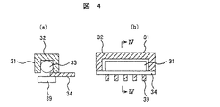
較正線源周方向移動装置37は、ガイドレール28及び較正線源装置29を備える。環状のガイドレール28は、孔部6を取囲むようにケーシングの被検診者保持装置14側の側面に取付けられる。較正線源装置29は較正線源駆動装置30及び較正線源31を有する。較正線源駆動装置30はガイドレール28に移動可能に取付けられる。較正線源駆動装置30は、図示されていないが、ガイドレール28のラックと噛合うピニオンを有し、このピニオンを減速機構を介して回転させるモーターを備える。較正線源31は、較正線源駆動装置30のケーシング(図示せず)に設置されて水平方向に伸縮が可能なアーム38の先端部に取付けられている。較正線源31は、図4に示すように、一方向に開口を有するγ線遮蔽体32内にγ線源33を収納している。躯体となるケーシング(図示せず)が、上記の開口部分を除いてγ線遮蔽体32の外側を覆っている。較正線源31は、γ線遮蔽体32の開口を塞ぐ移動可能なシャッター34を有する。γ線源33には、511keVのγ線を放出するGa−Ge線源を用いる。Ga−Ge線源の替りに662keVのγ線を放出するCs線源を用いてもよい。較正線源31はトランスミッションデータ撮影時に用いられる線源である。γ線遮蔽体32の開口の前面に配置されたコリメータ39が、シャッター34の開閉動作を妨げないようにγ線遮蔽体32に取付けられる。   The calibration source circumferential movement device 37 includes a guide rail 28 and a calibration source device 29. The annular guide rail 28 is attached to the side surface of the casing on the examinee holding device 14 side so as to surround the hole 6. The calibration source device 29 includes a calibration source driving device 30 and a calibration source 31. The calibration source driving device 30 is movably attached to the guide rail 28. Although not shown, the calibration radiation source driving device 30 includes a pinion that meshes with the rack of the guide rail 28 and includes a motor that rotates the pinion via a speed reduction mechanism. The calibration source 31 is attached to the distal end of an arm 38 that is installed in a casing (not shown) of the calibration source driving device 30 and can be expanded and contracted in the horizontal direction. As shown in FIG. 4, the calibration radiation source 31 houses a γ-ray source 33 in a γ-ray shield 32 having an opening in one direction. A casing (not shown) serving as a casing covers the outside of the γ-ray shield 32 except for the opening portion. The calibration radiation source 31 has a movable shutter 34 that closes the opening of the γ-ray shield 32. As the γ-ray source 33, a Ga—Ge source that emits 511 keV γ-rays is used. Instead of the Ga-Ge source, a Cs source that emits 662 keV gamma rays may be used. The calibration radiation source 31 is a radiation source used for transmission data imaging. A collimator 39 disposed in front of the opening of the γ-ray shield 32 is attached to the γ-ray shield 32 so as not to disturb the opening / closing operation of the shutter 34.

まず、放射線検査装置1Aを用いたトランスミッションデータ撮影について説明する。トランスミッションデータ撮影は、較正線源を用いて被検診者の体内のγ線透過率を計測する手法である。その計測要する時間は、1〜2分程度かかる。較正線源から放出されたγ線は、被検診者を透過した後、放射線検出器4で計測される。較正線源の放射能強度及び計測されたγ線に基づいて、被検診者の体内でのγ線減衰率を求める。求められたγ線減衰率は、PET検査における体内散乱(放射性薬剤に起因して体内で発生したγ線が体内で散乱,減衰する現象)の補正に用いられる。   First, transmission data imaging using the radiation inspection apparatus 1A will be described. Transmission data imaging is a technique for measuring the gamma ray transmittance in the body of a patient to be examined using a calibration radiation source. The time required for the measurement takes about 1 to 2 minutes. The γ-rays emitted from the calibration source are measured by the radiation detector 4 after passing through the examinee. Based on the radioactivity intensity of the calibration source and the measured γ-rays, the γ-ray attenuation rate in the body of the examinee is obtained. The obtained γ-ray attenuation rate is used to correct in-vivo scattering (a phenomenon in which γ-rays generated in the body due to radioactive drugs are scattered and attenuated in the body) in the PET examination.

トランスミッションデータ撮影を具体的に述べる。被検診者17が横たわっているベッド16が孔部6内に挿入される。トランスミッションデータ撮影を開始するとき、線源制御装置69はシャッター34を開く。γ線源33から放出されたγ線は、γ線遮蔽体32の開口及びコリメータ39を通って被検診者17に照射される。γ線源33からのγ線は、コリメータ39によって指向性が強くなり進行方向が特定される。駆動装置制御装置35は、トランスミッションデータ撮影を開始するとき、駆動開始信号を出力して、較正線源駆動装置30のモーターを回転させる。モーターの回転によって、較正線源駆動装置30はガイドレール28に沿って被検診者17の周囲を移動する。較正線源31は孔部6内で被検診者17の周囲を移動する。このため、較正線源31から放出された高指向性のγ線は、被検診者17に周方向のあらゆる位置から照射される。ベッド16が孔部6の反対側に向かって移動する。被検診者17を透過したそのγ線は放射線検出器4によって計測される。高指向性のγ線が照射されるため、放射線検出器4が計測するγ線は、非散乱のγ線であり、γ線源33より放出された時と同じ511keVのエネルギーを有する。   The transmission data shooting will be specifically described. The bed 16 on which the examinee 17 lies is inserted into the hole 6. When starting transmission data imaging, the radiation source controller 69 opens the shutter 34. The γ-rays emitted from the γ-ray source 33 are irradiated to the examinee 17 through the opening of the γ-ray shield 32 and the collimator 39. The directivity of the γ-ray from the γ-ray source 33 is increased by the collimator 39 and the traveling direction is specified. When starting transmission data imaging, the drive device control device 35 outputs a drive start signal to rotate the motor of the calibration source drive device 30. The calibration source driving device 30 moves around the patient 17 along the guide rail 28 by the rotation of the motor. The calibration source 31 moves around the patient 17 within the hole 6. For this reason, highly directional γ rays emitted from the calibration radiation source 31 are applied to the examinee 17 from any position in the circumferential direction. The bed 16 moves toward the opposite side of the hole 6. The gamma rays that have passed through the examinee 17 are measured by the radiation detector 4. Since highly directional γ-rays are irradiated, the γ-rays measured by the radiation detector 4 are non-scattered γ-rays and have the same energy of 511 keV as that emitted from the γ-ray source 33.

放射線検出器4は、被検診者17を透過したγ線を計測してγ線撮像信号を出力する。このγ線撮像信号に対して、後述のPET検査時に検出されるγ線撮像信号と同様に、γ線弁別装置8はパルス信号を発生し、同時計数装置9はパルス信号を計数してその計数値、及び対γ線を検出した2つの検出点(孔部6の軸心を中心にしてほぼ180°方向が異なって配置された一対の放射線検出器4の位置)を出力する。コンピュータ11は、その計数値、及び2つの検出点の位置情報を記憶装置12に記憶する。トランスミッションデータ撮影を終了するとき、駆動装置制御装置35は、駆動終了信号を出力して、較正線源駆動装置30のモーターを停止させる。そのとき、線源制御装置69はγ線の外部への放出を遮るために較正線源31のシャッター34を閉じる。   The radiation detector 4 measures γ-rays transmitted through the examinee 17 and outputs a γ-ray imaging signal. For this γ-ray imaging signal, the γ-ray discriminating device 8 generates a pulse signal, and the coincidence counting device 9 counts the pulse signal and counts it in the same manner as a γ-ray imaging signal detected at the time of PET inspection described later. The numerical value and two detection points (the positions of the pair of radiation detectors 4 arranged in different directions by about 180 ° around the axis of the hole 6) are output. The computer 11 stores the count value and the position information of the two detection points in the storage device 12. When ending transmission data imaging, the drive device control device 35 outputs a drive end signal to stop the motor of the calibration source drive device 30. At that time, the radiation source control device 69 closes the shutter 34 of the calibration radiation source 31 in order to block the emission of γ rays to the outside.

孔部6の半径方向に直線状に三層配置された3つの放射線検出器4(例えば、図1に示す放射線検出器4a,4b,4c)を、1つの放射線検出器グループと称する。本実施例は、複数の放射線検出器グループを有する。放出されたγ線のエネルギーが均一である場合、理論式によりγ線の検出効率が求まる。放射線検出器4は、検出部を5mm厚さのCdTeで構成した半導体放射線検出器であるため、511keVのγ線の検出効率は約20%である。そのため、1つの放射線検出器グループにおいて、一層目の放射線検出器4では入射γ線の約20%が、二層目の放射線検出器4では、一層目の放射線検出器4を透過した80%のγ線うちの約20%、つまり約16%のγ線が減衰する。三層目の放射線検出器4では、二層目の放射線検出器を透過した64%のγ線のうちの約20%、すなわち12.8%のγ線が減衰する。それらの減衰に応じたγ線撮像信号が一層目及び二層目の各放射線検出器4から出力される。そして、そのγ線撮像信号は、該当する信号処理装置7のγ線弁別装置8で散乱γ線を除去されてパルス信号に変えられる。その信号処理装置7の同時計数装置9はパルス信号を計数する。各層の放射線検出器4からのγ線撮像信号を独立に計測した場合、一層から三層の3つの放射線検出器4の検出効率の理論値の比(約20:16:12.8)と大きく異なる(例えば±5%以上異なる)場合は、いずれかの放射線検出器4が劣化して検出効率が低下していることになる。例えば、それらの3つの放射線検出器4のうち、どれか1つの放射線検出器4が劣化し、他の2つの放射線検出器4が正常に動作していた場合、1つの放射線検出器グループでの検出効率の実測値の比は前記の理論値の比に対して大きく異なる。このため、劣化した放射線検出器4を発見することができる。さらに、正常な2つの放射線検出器4の検出効率と前記比から求めた検出効率と、実測の検出効率から、劣化による検出効率の低下パーセンテージを計算できる。例えば、1つの放射線検出器グループにおける3つの放射線検出器4の計測値に基づいて求められた検出効率の実測値の比が、20:4:12.8になったとする。この場合、2層目の放射線検出器4の検出効率の実測値の比が、上記の検出効率の理論値の比と比較して12ポイント(低下パーセンテージ:75%)低下いる。このため。2層目の放射線検出器4は故障していると考えられる。   Three radiation detectors 4 (for example, radiation detectors 4a, 4b, and 4c shown in FIG. 1) arranged in three layers linearly in the radial direction of the hole 6 are referred to as one radiation detector group. This embodiment has a plurality of radiation detector groups. When the energy of emitted γ-rays is uniform, the detection efficiency of γ-rays can be obtained by a theoretical formula. Since the radiation detector 4 is a semiconductor radiation detector having a detection portion made of CdTe having a thickness of 5 mm, the detection efficiency of 511 keV γ rays is about 20%. Therefore, in one radiation detector group, about 20% of the incident γ-rays in the first-layer radiation detector 4 and 80% of the second-layer radiation detector 4 transmitted through the first-layer radiation detector 4. About 20% of γ rays, that is, about 16% of γ rays are attenuated. In the radiation detector 4 of the third layer, about 20% of 64% of γ rays transmitted through the radiation detector of the second layer, that is, 12.8% of γ rays are attenuated. A γ-ray imaging signal corresponding to the attenuation is output from each radiation detector 4 in the first and second layers. Then, the γ-ray imaging signal is converted into a pulse signal by removing the scattered γ-rays by the γ-ray discriminating device 8 of the corresponding signal processing device 7. The coincidence counting device 9 of the signal processing device 7 counts pulse signals. When the γ-ray imaging signals from the radiation detectors 4 of each layer are measured independently, the ratio of the theoretical values of the detection efficiencies of the three radiation detectors 4 of three to three layers (about 20: 16: 12.8) is large. If they are different (for example, ± 5% or more different), one of the radiation detectors 4 is deteriorated and the detection efficiency is lowered. For example, when any one of the three radiation detectors 4 is deteriorated and the other two radiation detectors 4 are operating normally, in one radiation detector group The ratio of measured values of detection efficiency is greatly different from the ratio of the theoretical values. For this reason, the deteriorated radiation detector 4 can be found. Furthermore, the percentage of decrease in detection efficiency due to deterioration can be calculated from the detection efficiency of the two normal radiation detectors 4, the detection efficiency obtained from the ratio, and the actual detection efficiency. For example, it is assumed that the ratio of the measured values of detection efficiency obtained based on the measured values of the three radiation detectors 4 in one radiation detector group is 20: 4: 12.8. In this case, the ratio of the actual measurement values of the detection efficiency of the radiation detector 4 of the second layer is 12 points (decrease percentage: 75%) lower than the ratio of the theoretical value of the detection efficiency. For this reason. The radiation detector 4 in the second layer is considered to have failed.

故障検知方法の概念について説明する。ある時点で、γ線源33から放出されたγ線は、コリメータ39の形状上、1つの放射線検出器グループ内の3つの放射線検出器4(例えば、図2に示す放射線検出器4a,4b,4c)に入射されるが、他の放射線検出器グループ(例えば、1つの放射線検出器グループに隣接した放射線検出器グループ)内の3つの放射線検出器4には入射されない。1つの放射線検出器グループに属する放射線検出器4の検出効率の比を、γ線透過距離及びγ線透過順序を考慮しながら、過去の放射線検出器4の劣化度合いを記したデータを用いて求める。また、1つの放射線検出器グループに属する放射線検出器4の検出効率の理論値の比を、シミュレーションまたは理論計算により求める。その1つの放射線検出器グループ内の各放射線検出器4から出力された各γ線撮像信号に基づいて求めた検出効率の実測値の比と、上記の検出効率の理論値の比とを比較し、その放射線検出器グループ内の各放射線検出器4が劣化していないか(または劣化しているか)を判断する。検出効率の実測値の比と、上記の検出効率の理論値の比との比較は、全放射線検出器グループに対して行う。検出効率の理論値の比は撮像装置2に設置された放射線検出器4が同じ種類であれば、どれか1つの放射線検出器グループで代表して算出すればよい。また、各γ線撮像信号に基づいて求めた検出効率の実測値の比と、過去の放射線検出器4の劣化度合いを記したデータを用いて求めた検出効率の比とを比較し、その放射線検出器グループ内の各放射線検出器4における劣化の進行状況を判断する。放射線検出器4が劣化している場合には、記憶装置12に劣化度合いの情報を記憶し、劣化及び故障をユーザーに知らせる。このような処理を各放射線検出器グループ毎に繰り返すことにより、撮像装置2に設置された各放射線検出器の検出効率の劣化度合いの把握及び故障した放射線検出器の摘出が行える。この故障検知方法の概念を適用した具体的な処理は、図5及び図6を用いて後述する。   The concept of the failure detection method will be described. At a certain point in time, the γ-rays emitted from the γ-ray source 33 are converted into three radiation detectors 4 in one radiation detector group (for example, the radiation detectors 4a, 4b, FIG. 4c) but not three radiation detectors 4 in other radiation detector groups (eg, radiation detector groups adjacent to one radiation detector group). The ratio of the detection efficiencies of the radiation detectors 4 belonging to one radiation detector group is obtained using data describing the degree of deterioration of the past radiation detectors 4 in consideration of the γ-ray transmission distance and the γ-ray transmission order. . Further, the ratio of the theoretical values of the detection efficiencies of the radiation detectors 4 belonging to one radiation detector group is obtained by simulation or theoretical calculation. The ratio of the actual value of the detection efficiency obtained based on each γ-ray imaging signal output from each radiation detector 4 in the one radiation detector group is compared with the ratio of the theoretical value of the above detection efficiency. Then, it is determined whether or not each radiation detector 4 in the radiation detector group has deteriorated (or has deteriorated). The comparison of the ratio of the actual measurement value of the detection efficiency and the ratio of the theoretical value of the detection efficiency is performed for all the radiation detector groups. If the radiation detectors 4 installed in the imaging apparatus 2 are of the same type, the ratio of theoretical values of detection efficiency may be calculated by representing one of the radiation detector groups. Moreover, the ratio of the actual value of the detection efficiency obtained based on each γ-ray imaging signal is compared with the ratio of the detection efficiency obtained using the data describing the degree of deterioration of the radiation detector 4 in the past. The progress of deterioration in each radiation detector 4 in the detector group is determined. When the radiation detector 4 is deteriorated, information on the degree of deterioration is stored in the storage device 12, and the user is notified of the deterioration and failure. By repeating such processing for each radiation detector group, it is possible to grasp the degree of deterioration of the detection efficiency of each radiation detector installed in the imaging apparatus 2 and to extract a failed radiation detector. Specific processing to which the concept of the failure detection method is applied will be described later with reference to FIGS.

次に、放射線検査装置1を用いたPET検査について説明する。被検体である被検診者17に予め注射等によりPET用薬剤を投与する。その後、PET用薬剤が被検診者17の体内に拡散して患部(例えば癌の患部)に集まって撮像可能な状態になるまでの所定時間の間、被検診者17は待機する。PET用薬剤は、検査する患部に応じて選ばれる。その所定時間経過後に、被検診者17はベッド16上に寝かせられ、撮像装置2を用いたPET検査が実施される。PET検査の実施の際には、ベッド16が撮像装置2に向かって移動され、被検診者17はベッド16と共に孔部6内に挿入される。被検診者17の体内の患部より放出された511keVのγ線(PET用薬剤に18Fを含んでいる場合)は、放射線検出器4に入射される。各放射線検出器4は、PET用薬剤に起因して患部から放出されたγ線をそれぞれ検出し、γ線の検出信号(以下、γ線撮像信号という)を出力する。γ線撮像信号は、該当する配線13を介して該当するγ線弁別装置8に入力される。γ線弁別装置8は、波形整形装置(図示せず)を有する。この波形整形装置は、入力したγ線撮像信号を時間的なガウス分布の波形を有するγ線撮像信号に変換する。PET用薬剤から放出された陽電子の陽電子消滅(患部で発生)により生成されるγ線のエネルギーは、511keVである。しかし、体内でγ線が散乱した場合、エネルギーは511keVより低くなる。γ線弁別装置8は、散乱γ線を除去するため、例えばエネルギーが511keVよりも低い400keVをエネルギー設定値として、このエネルギー設定値以上のエネルギーを有するγ線撮像信号を通過させるフィルター(図示せず)を備えている。このフィルターは波形整形装置から出力されたγ線撮像信号を入力する。ここで、例として、400keVをエネルギー設定値としたのは511keVのγ線が放射線検出器4に入射したときに発生するγ線撮像信号のばらつきを考慮したためである。γ線弁別装置8は、そのフィルターを通過したγ線撮像信号に対して、所定のエネルギーを有するパルス信号を発生させる。 Next, a PET inspection using the radiation inspection apparatus 1 will be described. A PET drug is administered in advance by injection or the like to the examinee 17 as the subject. Thereafter, the examinee 17 waits for a predetermined time until the PET drug diffuses in the body of the examinee 17 and collects in the affected area (for example, an affected area of cancer) and becomes ready for imaging. The PET drug is selected according to the affected area to be examined. After the predetermined time has passed, the examinee 17 is laid on the bed 16 and a PET examination using the imaging device 2 is performed. When performing the PET examination, the bed 16 is moved toward the imaging device 2, and the examinee 17 is inserted into the hole 6 together with the bed 16. The 511 keV γ rays (when 18 F is included in the PET drug) emitted from the affected part in the body of the examinee 17 enter the radiation detector 4. Each radiation detector 4 detects γ-rays emitted from the affected area due to the PET drug, and outputs a γ-ray detection signal (hereinafter referred to as a γ-ray imaging signal). The γ-ray imaging signal is input to the corresponding γ-ray discrimination device 8 via the corresponding wiring 13. The γ-ray discriminating device 8 has a waveform shaping device (not shown). This waveform shaping device converts an input γ-ray imaging signal into a γ-ray imaging signal having a temporal Gaussian distribution waveform. The energy of γ rays generated by positron annihilation of positrons emitted from the PET drug (generated in the affected area) is 511 keV. However, when γ rays are scattered in the body, the energy is lower than 511 keV. In order to remove scattered γ-rays, the γ-ray discriminating device 8 uses, for example, a filter (not shown) that passes a γ-ray imaging signal having energy equal to or higher than this energy set value, with 400 keV being lower than 511 keV as an energy set value. ). This filter inputs the γ-ray imaging signal output from the waveform shaping device. Here, as an example, the energy setting value is set to 400 keV because the variation of γ-ray imaging signals generated when 511 keV γ-rays enter the radiation detector 4 is taken into consideration. The γ-ray discriminating device 8 generates a pulse signal having a predetermined energy for the γ-ray imaging signal that has passed through the filter.

同時計数装置9は、全てのγ線弁別装置8から出力されたパルス信号を入力し、各放射線検出器4から出力された各γ線撮像信号に対する計数値を求める。更に、同時計数装置9は、トランスミッションデータ撮影時と同様に、前述の対γ線の各γ線に対するそれぞれのパルス信号を用いて、その対γ線を検出した2つの検出点の位置情報を求める。これらの検出点の位置情報は、コンピュータ11に伝えられ、コンピュータ11によって記憶装置12に記憶される。前述の各γ線撮像信号に対する計数値も、コンピュータ11により記憶装置12に記憶される。   The coincidence counting device 9 receives the pulse signals output from all the γ-ray discriminating devices 8 and obtains a count value for each γ-ray imaging signal output from each radiation detector 4. Further, the coincidence counting device 9 obtains position information of two detection points at which the pair of γ-rays are detected by using the respective pulse signals for the γ-rays of the paired γ-rays as in the transmission data imaging. . The position information of these detection points is transmitted to the computer 11 and stored in the storage device 12 by the computer 11. The count value for each γ-ray imaging signal is also stored in the storage device 12 by the computer 11.

コンピュータ11は、その計数値等を用いて図5及ぶ図6に示す処理手順を実行して被検診者17の断層像を再構成する。その処理手順の内容を詳細に説明する。PET検査時における計数値及び該当する検出点の位置情報、及びトランスミッション撮影時における計数値が、記憶装置12から読み出されて入力される(ステップ40)。放射線検出器グループ内の各放射線検出器に対する検出効率の理論値の比を算出する(ステップ41)。この論理比は、被検診者17から放出されたγ線透過距離(PET用薬剤に含まれる放射性核種に応じて変わる)及びγ線透過順序を用いた理論計算により求められる。18Fを含んでいるPET用薬剤を被検診者17に投与した場合には、放射線検出器グループ内における一層から三層の3つの放射線検出器4に対する検出効率の理論値の比は約20:16:12.8である。本実施例のようにその都度、検出効率の理論値の比を算出するのではなく、含まれる放射性核種の異なる各PET用薬剤に対して、放射線検出器グループ内における全放射線検出器に対する検出効率の理論値の比を予め算出して記憶装置12に記憶させておいてもよい。 The computer 11 reconstructs a tomographic image of the examinee 17 by executing the processing procedure shown in FIGS. The contents of the processing procedure will be described in detail. The count value at the time of PET inspection, the position information of the corresponding detection point, and the count value at the time of transmission imaging are read out from the storage device 12 and input (step 40). The ratio of the theoretical value of the detection efficiency for each radiation detector in the radiation detector group is calculated (step 41). This logical ratio is obtained by theoretical calculation using the γ-ray transmission distance (which varies depending on the radionuclide contained in the PET drug) and the γ-ray transmission order emitted from the examinee 17. When a PET drug containing 18 F is administered to the examinee 17, the ratio of the theoretical value of the detection efficiency to the three radiation detectors 4 in one to three layers in the radiation detector group is about 20: 16: 12.8. Instead of calculating the ratio of theoretical values of detection efficiency each time as in the present embodiment, the detection efficiency for all radiation detectors in the radiation detector group for each PET drug having a different radionuclide is included. The ratio of the theoretical values may be calculated in advance and stored in the storage device 12.

次に、劣化した放射線検出器4を抽出する(ステップ42)。ステップ42の処理は、放射線検出器グループ毎に行われ、図6を用いて具体的に説明する。まず、1つの放射線検出器グループを選択する(ステップ50)。選択された放射線検出器グループ内の放射線検出器に対する検出効率の実測値の比を算出する(ステップ51)。すなわち、選択された放射線検出器グループ内の各放射線検出器4から出力されたそれぞれのγ線撮像信号に基づいて得られた各計数値を用いて、それらの放射線検出器に対する検出効率の実測値の比を算出する。検出効率の実測値の比と検出効率の理論値の比との差が設定範囲(理論値の比に対して±5%の範囲)内にあるかを判定する(ステップ52)。その差が設定範囲内にある場合(「Yes」の場合)は、選択された放射線検出器グループ内の各放射線検出器4は、劣化しておらず正常に動作している。その差が設定範囲内にない場合(「No」の場合)は、その放射線検出器グループ内の劣化している放射線検出器(劣化放射線検出器という)4を、記憶装置12に記憶させる(ステップ53)。その差が設定範囲内にない場合は、その放射線検出器グループ内のいずれか(または全て)の放射線検出器4が劣化していることを意味する。放射線検出器グループ内の劣化放射線検出器は、各放射線検出器における検出効率の実測値の比の値とその理論値の比の値とを前述のように比較することによって確認できる。次に、劣化放射線検出器4に関する劣化情報を表示装置13に出力する(ステップ54)。劣化放射線検出器4に関する劣化情報は、記憶装置12に記憶されている過去の放射線検出器4の劣化度合いを記したデータを用いて求めた検出効率の比の情報である。オペレータは、表示装置13に表示された劣化放射線検出器4に関する劣化情報に基づいて劣化放射線検出器4の劣化の進行状況を判断できる。劣化の進行度合いが大きな劣化放射線検出器4は新しい放射線検出器4と交換する必要がある。劣化放射線検出器4の検出効率を補正する(ステップ55)。例えば、1つの放射線検出器グループ内の放射線検出器4a及び4cの実測値の比の値が理論値の比の値と一致しており、放射線検出器4bの実測値の比の値が理論値の比よりかなり低い場合は、放射線検出器4a及び4cの各検出効率の実測値の比、及びに放射線検出器4a,4b及び4cの検出効率の理論値の比に基づいて推測される検出効率を放射線検出器4bの検出効率として補正する。この補正された検出効率に基づいて求められた計数値は、放射線検出器4bの計数値として記憶装置12に記憶される。   Next, the deteriorated radiation detector 4 is extracted (step 42). The processing of step 42 is performed for each radiation detector group, and will be specifically described with reference to FIG. First, one radiation detector group is selected (step 50). A ratio of measured values of detection efficiency to the radiation detectors in the selected radiation detector group is calculated (step 51). That is, using each count value obtained based on each γ-ray imaging signal output from each radiation detector 4 in the selected radiation detector group, an actual measurement value of the detection efficiency for those radiation detectors. The ratio is calculated. It is determined whether or not the difference between the ratio of the actually measured detection efficiency and the ratio of the theoretical detection efficiency is within a set range (± 5% of the theoretical value ratio) (step 52). When the difference is within the set range (in the case of “Yes”), each radiation detector 4 in the selected radiation detector group is not deteriorated and operates normally. When the difference is not within the set range (in the case of “No”), the deteriorated radiation detector (referred to as a deteriorated radiation detector) 4 in the radiation detector group is stored in the storage device 12 (step) 53). If the difference is not within the set range, it means that any (or all) radiation detectors 4 in the radiation detector group have deteriorated. The deteriorated radiation detector in the radiation detector group can be confirmed by comparing the ratio value of the actual measurement value of the detection efficiency in each radiation detector with the ratio value of the theoretical value as described above. Next, the deterioration information regarding the deterioration radiation detector 4 is output to the display device 13 (step 54). The deterioration information regarding the deterioration radiation detector 4 is information on the ratio of detection efficiency obtained using data describing the degree of deterioration of the past radiation detector 4 stored in the storage device 12. The operator can determine the progress of deterioration of the deteriorated radiation detector 4 based on the deterioration information regarding the deteriorated radiation detector 4 displayed on the display device 13. The deteriorated radiation detector 4 having a large degree of deterioration needs to be replaced with a new radiation detector 4. The detection efficiency of the deteriorated radiation detector 4 is corrected (step 55). For example, the ratio value of the actual measurement values of the radiation detectors 4a and 4c in one radiation detector group matches the value of the ratio of the theoretical value, and the ratio value of the actual measurement value of the radiation detector 4b is the theoretical value. If the ratio is much lower than the ratio, the detection efficiency estimated based on the ratio of the actual measurement values of the radiation detectors 4a and 4c and the ratio of theoretical values of the detection efficiencies of the radiation detectors 4a, 4b and 4c Is corrected as the detection efficiency of the radiation detector 4b. The count value obtained based on the corrected detection efficiency is stored in the storage device 12 as the count value of the radiation detector 4b.

ステップ52が「Yes」のときまたはステップ55の処理が終了したとき、「選択されない放射線グループが残っている」かについて判定する(ステップ56)。ステップ56の判定が「Yes」の場合には、ステップ57で次の放射線検出器グループが選択され、ステップ56の判定が「No」になるまで、ステップ51以降の処理が実行される。ステップ56の判定が「No」になったとき、トランスミッション像を作成する(ステップ43)。すなわち、トランスミッションデータ撮影時に得られたγ線撮像信号に対する計数値を用いて、被検診者17の体内の各ボクセルにおけるγ線減衰率を算出する。各ボクセルにおけるこのγ線減衰率は記憶装置12に記憶される。   When Step 52 is “Yes” or when the processing of Step 55 is completed, it is determined whether “an unselected radiation group remains” (Step 56). If the determination in step 56 is “Yes”, the next radiation detector group is selected in step 57, and the processing from step 51 is executed until the determination in step 56 becomes “No”. When the determination in step 56 is “No”, a transmission image is created (step 43). That is, the gamma ray attenuation rate in each voxel in the body of the examinee 17 is calculated using the count value for the gamma ray imaging signal obtained at the time of transmission data imaging. This γ-ray attenuation rate in each voxel is stored in the storage device 12.

次に、各放射線検出器間における体内の減衰補正計数を算出する(ステップ44)。PET検査では対γ線が放出されるため、対γ線の体内における動距離の和に基づいて体内の減衰補正計数を算出する。PET検査時に得られた計数値,検出点の位置情報及びステップ43で算出したγ線減衰率を用いて、後述のステップ47で述べる断層像の再構成の手法により、被検診者17の断層像を再構成する。まず、ステップ43で得られた各ボクセルにおけるγ線減衰率を用いて、対γ線を検出するある一対の放射線検出器4(例えば、図7(b)に示す放射線検出器4fと放射線検出器4g)間におけるガンマ線減衰率をフォワードプロジェクション法により求める。求められたそのガンマ線減衰率の逆数が減衰補正計数である。ステップ45において、減衰補正計数を用い体内減衰補正を行う。PET検査時において得られた計数値にその減衰補正計数を掛け合わせることによって、PET検査時において得られた計数値の補正が行われる。被検診者17の患部で発生したγ線は体内を透過する間に吸収・減衰されるが、上記の減衰補正計数を用いた補正をPET検査時において得られた計数値に対して行うことによって、更に高精度な計数値を得ることができる。   Next, an attenuation correction coefficient in the body between each radiation detector is calculated (step 44). In the PET examination, γ rays are emitted, so the attenuation correction coefficient in the body is calculated based on the sum of the moving distances of the γ rays in the body. Using the count value obtained at the PET examination, the position information of the detection point, and the γ-ray attenuation rate calculated in step 43, a tomographic image of the examinee 17 is obtained by the tomographic image reconstruction method described in step 47 described later. Reconfigure. First, a pair of radiation detectors 4 (for example, the radiation detector 4f and the radiation detector shown in FIG. 7B) that detect γ-rays using the γ-ray attenuation rate in each voxel obtained in step 43. 4g), the gamma ray attenuation rate is obtained by the forward projection method. The reciprocal of the obtained gamma ray attenuation rate is the attenuation correction coefficient. In step 45, internal attenuation correction is performed using the attenuation correction coefficient. The count value obtained at the time of PET inspection is corrected by multiplying the count value obtained at the time of PET inspection by the attenuation correction count. The γ rays generated in the affected area of the examinee 17 are absorbed and attenuated while passing through the body, but the correction using the attenuation correction count is performed on the count value obtained at the time of the PET examination. Further, a highly accurate count value can be obtained.

更に、ステップ46において、放射線検出器の検出効率差を反映してγ線撮像信号に対する補正を行う。PET検査では対γ線が放出されるため、対γ線のそれぞれのγ線が到達する2つの放射線検出器グループ内の検出効率を用いて計数値を補正する必要がある。つまり、その2つの放射線検出器グループ内でそれぞれγ線を検出した放射線検出器4の検出効率の補正計数を両方かけることにより補正する。これを具体的に説明する。各放射線検出器4における検出効率についての、フォワードプロジェクション撮像時における理論値と実測値との差がステップ42で求められている。放射線検出器グループjにおいて、i番目の放射線検出器4に対する、フォワードプロジェクション撮像時における、検出効率の理論値をXfiij、及びステップ45で補正された計数値をXseijとする。い番目の検出器が故障していると判定され、k番目の検出器が正常である場合、i番目の放射線検出器に対する補正PET計数値Xsiijは(2)式で表される。iは孔部6に近い放射線検出器4から1,2,3…となる。(2)式で求められた補正PET計数値(放射線 Xsiij=Xsekj×Xfiij/Xfikj …(2)
検出器の検出効率差を反映して補正された計数値)は記憶装置12に記憶される。
Further, in step 46, the γ-ray imaging signal is corrected by reflecting the difference in detection efficiency of the radiation detector. Since PET examination emits γ-rays, it is necessary to correct the count value by using the detection efficiencies in the two radiation detector groups to which the respective γ-rays of the γ-rays reach. That is, the correction is performed by multiplying both the detection efficiency correction counts of the radiation detectors 4 that have detected γ-rays in the two radiation detector groups. This will be specifically described. The difference between the theoretical value and the actual measurement value at the time of forward projection imaging with respect to the detection efficiency in each radiation detector 4 is obtained in step 42. In the radiation detector group j, the theoretical value of detection efficiency at the time of forward projection imaging for the i-th radiation detector 4 is Xfi ij , and the count value corrected in step 45 is Xse ij . When it is determined that the second detector is faulty and the k-th detector is normal, the corrected PET count value Xsi ij for the i-th radiation detector is expressed by equation (2). i becomes 1, 2, 3,... from the radiation detector 4 close to the hole 6. Corrected PET count value obtained by equation (2) (radiation Xsi ij = Xse kj × Xfi ij / Xfi kj (2)
The count value corrected to reflect the difference in detection efficiency of the detector is stored in the storage device 12.

患部(例えば癌の患部)を含む、被検診者17の断層像を再構成する(ステップ47)。ステップ47では、ステップ46における補正によって得られた補正PET計数値Xsiij、及び検出点の位置情報を用いて、断層像の再構成が行われる。その断層像の再構成について、具体的に説明する。その断層像再構成の処理は、フィルタードバックプロジェクション法を適用し、上記計数値の情報及び検出点の位置情報を用いてコンピュータ11で行われる。コンピュータ11は、断層像再構成装置である。その断層像は、フィルタードバックプロジェクション法では、前述した文献に記載されているように、距離t及び角度θの2つのパラメータによりソートされたデータを用いて再構成される。距離t及び角度θについて、図2を用いて具体的に説明する。被検診者17の患部から放出された対γ線が放射線検出器4d,4eで検出されたとする。放射線検出器4dと放射線検出器4eとを結ぶ直線18の中点を通り、直線18に垂直に交わる直線が19である。基準軸20(一番内側の放射線検出器4が配置される円の中心点、すなわち孔部6の中心点を通る直線であればどの方向でもよい)と直線19とのなす角度がθであり、孔部6の中心点21と直線18との距離がtである。角度θは、対γ線を検出した放射線検出器4dと放射線検出器4eとを結ぶ直線18が、基準軸20に対してどれだけ回転しているかを表している。 A tomographic image of the examinee 17 including the affected part (for example, an affected part of cancer) is reconstructed (step 47). In step 47, the tomogram is reconstructed using the corrected PET count value Xsi ij obtained by the correction in step 46 and the position information of the detection point. The reconstruction of the tomographic image will be specifically described. The tomographic image reconstruction processing is performed by the computer 11 using the filtered back projection method and using the count value information and the detection point position information. The computer 11 is a tomographic image reconstruction device. In the filtered back projection method, the tomographic image is reconstructed using data sorted by the two parameters of the distance t and the angle θ, as described in the above-mentioned document. The distance t and the angle θ will be specifically described with reference to FIG. It is assumed that the counter γ-rays emitted from the affected part of the examinee 17 are detected by the radiation detectors 4d and 4e. Reference numeral 19 denotes a straight line that passes through the midpoint of the straight line 18 connecting the radiation detector 4d and the radiation detector 4e and intersects the straight line 18 perpendicularly. The angle between the reference axis 20 (which may be any direction as long as it is a straight line passing through the center point of the circle on which the innermost radiation detector 4 is arranged, that is, the center point of the hole 6) and the straight line 19 is θ. The distance between the center point 21 of the hole 6 and the straight line 18 is t. The angle θ represents how much the straight line 18 connecting the radiation detector 4d and the radiation detector 4e that has detected the paired γ rays is rotated with respect to the reference axis 20.

放射線検査装置1は、孔部6の半径方向において複数の放射線検出器4を積層配置しているが、この積層配置によって以下に示す新しい機能を発揮できる。例えば、図7(a)に示すように被検診者17の体内のγ線対発生点22(患部)より発生した2つのγ線23a,23bが放射線検出器4f,4gに入射した場合を考える。検出器の内部のどの位置で減衰したかはわからないため、従来法では一対の放射線検出器4f,4hの先端位置を結ぶ線、つまり図7(b)に示す線24を検出線とした。しかし、放射線検査装置1では、孔部6の半径方向において放射線検出器4を積層配置しているため、その半径方向で外側に位置する放射線検出器4gのγ線撮像信号が得られ、放射線検出器4fと放射線検出器4gとを結ぶ線25を検出線とすることができる。つまり、従来の検出器ではわからなかった検出器の奥行き方向における減衰位置を把握することができる。この結果、検出線25は、γ線対が発生した位置を正確に通るため、画像の精度が向上する。この結果、検出線がより実際のガンマ線対発生点に近くなるため、測定データの精度が向上する。   In the radiation inspection apparatus 1, a plurality of radiation detectors 4 are stacked in the radial direction of the hole 6, and the following new functions can be exhibited by this stacked arrangement. For example, as shown in FIG. 7A, a case is considered where two γ rays 23a and 23b generated from a γ ray pair generation point 22 (affected part) in the body of the examinee 17 enter the radiation detectors 4f and 4g. . Since it is not known at which position inside the detector it is attenuated, in the conventional method, the line connecting the tip positions of the pair of radiation detectors 4f and 4h, that is, the line 24 shown in FIG. However, in the radiation inspection apparatus 1, since the radiation detectors 4 are stacked in the radial direction of the hole 6, a γ-ray imaging signal of the radiation detector 4g positioned outside in the radial direction is obtained, and radiation detection is performed. A line 25 connecting the detector 4f and the radiation detector 4g can be used as a detection line. That is, it is possible to grasp the attenuation position in the depth direction of the detector that was not known with the conventional detector. As a result, the detection line 25 accurately passes through the position where the γ ray pair is generated, so that the accuracy of the image is improved. As a result, since the detection line is closer to the actual generation point of the gamma ray pair, the accuracy of the measurement data is improved.

次に得られた結果をフィルタードバックプロジェクションにより再構成する。コンピュータによって再構成された断層のデータは、記憶装置12に記憶されると共に、表示装置13に表示される。   The obtained results are then reconstructed by filtered back projection. The tomographic data reconstructed by the computer is stored in the storage device 12 and displayed on the display device 13.

(1)本実施例は、放射線検出器4を、孔部6の軸方向及び周方向のみならず、半径方向にも複数配置することにより、従来のPET検査に用いられる放射線検出器のように信号伝達物質を減らさずに、孔部6の半径方向において細分した位置でのγ線撮像信号を得ることができる。このため、本実施例は、孔部6の半径方向においてγ線が到達した正確な位置情報(γ線撮像信号を出力した放射線検出器4の位置情報)を得ることができる。なお、従来のPET検査では、孔部6の半径方向には1つの放射線検出器を配置し、この放射線検出器内部に反射材を配置して信号伝達物質が光電子増倍管に到達したパターンにより、孔部6の半径方向においてγ線が到達した位置の情報を求めていた。このとき、反射材により信号伝達物質の一部が放射線検出器内で減衰したり、放射線検出器外へ反射してしまうため、信号伝達物質が減少し、エネルギー分解能の低下が発生した。   (1) In this embodiment, a plurality of radiation detectors 4 are arranged not only in the axial direction and circumferential direction of the hole 6 but also in the radial direction, so that the radiation detector 4 is used as in a conventional PET detector. A gamma ray imaging signal at a position subdivided in the radial direction of the hole 6 can be obtained without reducing the signal transmitting substance. For this reason, this embodiment can obtain accurate position information (position information of the radiation detector 4 that outputs the γ-ray imaging signal) where the γ-rays have reached in the radial direction of the hole 6. In the conventional PET inspection, one radiation detector is arranged in the radial direction of the hole 6, and a reflecting material is arranged inside the radiation detector so that the signal transmitting substance reaches the photomultiplier tube. The information of the position where the γ rays reached in the radial direction of the hole 6 was obtained. At this time, a part of the signal transmission material is attenuated in the radiation detector or reflected to the outside of the radiation detector by the reflecting material, so that the signal transmission material is reduced and the energy resolution is lowered.

(2)本実施例は、孔部6の半径方向において独立した複数の放射線検出器4を配置しているため、それぞれの放射線検出器の信号伝達物質の全てをγ線の検出に使用でき、放射線検出器のエネルギー分解能が向上する。エネルギー分解能の高い放射線検出器をPET検査で用いた場合、散乱によりエネルギーが減衰したγ線と無散乱の511keVのエネルギーのγ線との区別が可能になる。その結果、γ線弁別装置8のフィルターにより散乱線をより多く除去することが可能となる。   (2) In this embodiment, since a plurality of independent radiation detectors 4 are arranged in the radial direction of the hole 6, all of the signal transmitting substances of the respective radiation detectors can be used for detecting γ-rays. The energy resolution of the radiation detector is improved. When a radiation detector with a high energy resolution is used in PET inspection, it becomes possible to distinguish between γ-rays whose energy has been attenuated by scattering and γ-rays having a non-scattering energy of 511 keV. As a result, more scattered rays can be removed by the filter of the γ-ray discriminating device 8.

(3)本実施例は、放射線検出器内の信号伝達物質数を減らすことなく孔部6の半径方向におけるγ線の正確な到達位置の情報を取得できるため、γ線の正確な到達位置の情報を使用することによる断層像の精度の向上と、放射線検出器の反射材が不要であることにより信号伝達物質の減少が阻止でき、エネルギー分解能が向上して散乱線の断層像再構成への影響を抑えることが可能となった。その結果、本実施例は、断層像の精度、つまりPET検査の精度を向上できる。   (3) Since this embodiment can acquire information on the exact arrival position of γ rays in the radial direction of the hole 6 without reducing the number of signal transmitting substances in the radiation detector, The use of information improves the accuracy of tomographic images, and the need for a reflector for the radiation detector prevents the reduction of signal transmission materials, improving the energy resolution and reconstructing tomographic images of scattered radiation. It became possible to suppress the influence. As a result, the present embodiment can improve the accuracy of tomographic images, that is, the accuracy of PET inspection.

(4)本実施例は、放射線検出器4として半導体放射線検出器を用いているため、孔部6の半径方向に複数の放射線検出器4を配置することができ、そのように複数の放射線検出器4を配置しても撮像装置2が大きくならない。   (4) Since this embodiment uses a semiconductor radiation detector as the radiation detector 4, a plurality of radiation detectors 4 can be arranged in the radial direction of the hole 6, and thus a plurality of radiation detections are performed. Even if the device 4 is arranged, the imaging device 2 does not become large.

(5)本実施例は、1つの放射線検出器グループ内の各放射線検出器4に対する検出効率の実測値の比とそれらの放射線検出器4に対する理論値の比とを比較することによって、それらの放射線検出器4のうちで劣化している放射線検出器4を簡単に見つけることができる。特に、孔部6の半径方向において、複数の放射線検出器4を直線状に配置した場合には、上記の劣化している放射線検出器4を簡単に見つけられる。   (5) In this embodiment, by comparing the ratio of the actual measurement value of the detection efficiency with respect to each radiation detector 4 in one radiation detector group and the ratio of the theoretical value with respect to those radiation detectors 4, Of the radiation detectors 4, the radiation detector 4 that is deteriorated can be easily found. In particular, when a plurality of radiation detectors 4 are linearly arranged in the radial direction of the hole 6, the above-described deteriorated radiation detector 4 can be easily found.

(6)本実施例は、検出効率差によるノイズ及び体内散乱ノイズを一台の撮像装置2を用いた撮像によって補正することができる。   (6) In this embodiment, noise due to a difference in detection efficiency and in-body scattering noise can be corrected by imaging using a single imaging device 2.

本実施例のステップ47では、ステップ45で補正した計数値をステップ46で検出効率差を反映して補正した補正PET係数値を用いて断層像を再構成しているが、ステップ46での補正を省略してステップ45で補正した計数値を用いてステップ47で断層像を再構成することも可能である。   In step 47 of the present embodiment, the tomographic image is reconstructed using the corrected PET coefficient value corrected in step 46 to reflect the difference in detection efficiency in step 46, but the correction in step 46 is performed. It is also possible to reconstruct a tomographic image in step 47 using the count value corrected in step 45, omitting.

本実施例では、三個の放射線検出器4を孔部6の半径方向に直線状に配置しているが、三個の放射線検出器をそのように直線状ではなく、内側から二番目の放射線検出器4を孔部6の周方向にずらして(例えば一番内側の2つの放射線検出器の間の空間に面するように)配置してもよい。このように、孔部6の半径方向に複数の放射線検出器4が直線状に配置されていない場合には、撮像装置を組立てた後に、各放射線検出器に到達するまでのγ線の減衰率を試験により測定しなければならない。前述の実施例のように、孔部6の半径方向に複数の放射線検出器4が直線状に配置されている場合には、放射線検出器4のγ線の減衰率が分かっているため、そのような試験を行う必要がない。   In the present embodiment, the three radiation detectors 4 are linearly arranged in the radial direction of the hole 6, but the three radiation detectors are not so linear and are the second radiation from the inside. The detector 4 may be arranged so as to be shifted in the circumferential direction of the hole 6 (for example, facing the space between the two innermost radiation detectors). As described above, when the plurality of radiation detectors 4 are not linearly arranged in the radial direction of the hole 6, the attenuation rate of γ rays until the radiation detectors are reached after the imaging device is assembled. Shall be measured by testing. When the plurality of radiation detectors 4 are linearly arranged in the radial direction of the hole 6 as in the above-described embodiment, the attenuation rate of γ rays of the radiation detector 4 is known. There is no need to conduct such tests.

なお、本実施例ではトランスミッションの撮影によるγ線の体内吸収補正を行ったが、その補正の替りに一般的に用いられているPETの補正技術を用いてもよい。体内吸収補正の他の方法について説明する。別に設置されたX線CT装置を用いて被検診者17を透過したX線をX線CT装置の放射線検出器で測定する。その放射線検出器から出力されたX線の検出信号の減衰率を用いて被検診者17の断層像を再構成し、体内の各位置でのCT値を求める。得られたCT値から、体内の各位置における物質組成を見積もる。そして物質組成データから511keVにおける各位置での線減弱係数を見積もる。得られた線減弱係数データを用いて、PET検査において一対のγ線を検出した一対の半導体素子部間の線減弱係数をフォワードプロジェクション法により求める。求められたその線減弱係数の逆数をγ線撮像信号の計数値に掛け合わせることにより体内減衰によるデータ差の補正がなされる。   In the present embodiment, the in-vivo absorption correction of γ-rays is performed by imaging the transmission, but a PET correction technique that is generally used may be used instead of the correction. Another method for correcting in-vivo absorption will be described. Using an X-ray CT apparatus installed separately, X-rays that have passed through the examinee 17 are measured with a radiation detector of the X-ray CT apparatus. Using the attenuation rate of the X-ray detection signal output from the radiation detector, a tomographic image of the examinee 17 is reconstructed, and CT values at each position in the body are obtained. The substance composition at each position in the body is estimated from the obtained CT value. Then, the linear attenuation coefficient at each position at 511 keV is estimated from the material composition data. Using the obtained linear attenuation coefficient data, a linear attenuation coefficient between a pair of semiconductor element portions in which a pair of γ-rays is detected in the PET inspection is obtained by a forward projection method. The data difference due to internal attenuation is corrected by multiplying the reciprocal of the obtained linear attenuation coefficient by the count value of the γ-ray imaging signal.

本発明の他の実施例である放射線検査装置を、図8を用いて以下に説明する。本実施例の放射線検査装置1Aは、SPECT検査に用いられるものであり、放射線検査装置1の撮像装置2を撮像装置2Aに、信号処理装置7を信号処理装置7Aに替えた構成を有する。放射線検査装置1Aにおけるそれら以外の構成は放射線検査装置1と同じである。信号処理装置7Aは、γ線弁別装置8A、及びγ線弁別装置8Aに接続された計数装置36を有し、放射線検出器4毎に設けられる。γ線弁別装置8Aは、実施例1におけるγ線弁別装置8のフィルターにおけるエネルギー設定値400keVを120keVに変えた構成を有する。撮像装置2Aは、撮像装置2の構成にコリメータ27を付加し、更に撮像装置2の構成のうち較正線源周方向移動装置37を較正線源周方向移動装置37Aに替えたものである。コリメータ27は、最も内側に配置される放射線検出器4の内側に配置され、放射線検出器支持板5に取付けられる。コリメータ27は、環状をしており、放射線検出器4に対して斜め入射使用とするγ線を吸収する。本実施例も複数の放射線検出器グループを有する。   A radiation inspection apparatus according to another embodiment of the present invention will be described below with reference to FIG. The radiation inspection apparatus 1A of the present embodiment is used for SPECT inspection, and has a configuration in which the imaging apparatus 2 of the radiation inspection apparatus 1 is replaced with an imaging apparatus 2A, and the signal processing apparatus 7 is replaced with a signal processing apparatus 7A. Other configurations of the radiation inspection apparatus 1A are the same as those of the radiation inspection apparatus 1. The signal processing device 7A includes a γ-ray discriminating device 8A and a counting device 36 connected to the γ-ray discriminating device 8A, and is provided for each radiation detector 4. The γ-ray discriminating device 8A has a configuration in which the energy set value 400 keV in the filter of the γ-ray discriminating device 8 in the first embodiment is changed to 120 keV. The imaging device 2A is obtained by adding a collimator 27 to the configuration of the imaging device 2, and further replacing the calibration source circumferential direction moving device 37 with a calibration source circumferential direction moving device 37A in the configuration of the imaging device 2. The collimator 27 is disposed inside the radiation detector 4 disposed on the innermost side, and is attached to the radiation detector support plate 5. The collimator 27 has an annular shape and absorbs γ-rays that are used obliquely with respect to the radiation detector 4. This embodiment also has a plurality of radiation detector groups.

較正線源周方向移動装置37Aは、ガイドレール28及び較正線源装置29Aを備える。較正線源装置29Aは較正線源駆動装置30,較正線源31A及びアーム38を有する。較正線源31Aは、アーム38に取付けられる。図9に示す較正線源31Aは、較正線源31のγ線源33をγ線源33Aに替えると共に、較正線源31からコリメータ39を取除いた構成を有する。γ線源33Aは、141keV前後のγ線を放出する線源を用いる。例えば120keVの57Coを用いる。 The calibration source circumferential movement device 37A includes a guide rail 28 and a calibration source device 29A. The calibration radiation source device 29A includes a calibration radiation source driving device 30, a calibration radiation source 31A, and an arm 38. The calibration radiation source 31A is attached to the arm 38. A calibration source 31A shown in FIG. 9 has a configuration in which the γ-ray source 33 of the calibration source 31 is replaced with a γ-ray source 33A and the collimator 39 is removed from the calibration source 31. The γ-ray source 33A uses a radiation source that emits γ-rays of around 141 keV. For example, 120 keV 57 Co is used.

まず、放射線検査装置1Aを用いたトランスミッションデータ撮影は、放射線検査装置1を用いた場合と同様に行われ、被検診者の体内でのγ線減衰率を求める。得られたγ線減衰率は、SPECT検査における体内散乱の補正に用いられる。放射線検出器4は本例では120keVのエネルギーを有する。   First, transmission data imaging using the radiation inspection apparatus 1A is performed in the same manner as when the radiation inspection apparatus 1 is used, and a gamma ray attenuation rate in the body of the examinee is obtained. The obtained γ-ray attenuation rate is used for correction of internal scattering in the SPECT examination. The radiation detector 4 has an energy of 120 keV in this example.

放出されたγ線のエネルギーが均一である場合、理論式によりγ線の検出効率が求まる。放射線検出器4は、検出部を5mm厚さのCdTeで構成した半導体放射線検出器であるため、141keVのγ線の検出効率は約80%である。本例では120keVの線源を用いているが、検出効率は大差がないので141keVとして処理しても妥当な結果になる。そのため、1つの放射線検出器グループの三層配置された3つの放射線検出器4において、一層目の放射線検出器4で入射γ線の約80%が、二層目の放射線検出器4では、一層目の放射線検出器4を透過した20%のγ線うちの約80%、つまり約16%のγ線が減衰する。三層目の放射線検出器4では、二層目の放射線検出器を透過した4%のγ線のうちの約80%、すなわち3.2%のγ線が減衰する。それらの減衰に応じたγ線撮像信号が各放射線検出器4から出力される。各層の放射線検出器4からのγ線撮像信号を独立に計測した場合、各層の放射線検出器4の検出効率の実測値の比が理論値の比(80:16:3.2)と大きく異なる(例えば±5%以上異なる)場合は、いずれかの放射線検出器4が劣化している。本実施例も、実施例1と同様にして、1つの放射線検出器グループ内における劣化放射線検出器4を見つけることができ、劣化による検出効率の低下パーセンテージを得ることができる。本実施例における故障検知方法の概念について説明する。   When the energy of emitted γ-rays is uniform, the detection efficiency of γ-rays can be obtained by a theoretical formula. Since the radiation detector 4 is a semiconductor radiation detector having a detection unit made of CdTe having a thickness of 5 mm, the detection efficiency of 141 keV γ rays is about 80%. In this example, a 120 keV radiation source is used, but the detection efficiency is not very different, so even if it is processed as 141 keV, a reasonable result is obtained. Therefore, in the three radiation detectors 4 arranged in three layers of one radiation detector group, about 80% of the incident γ-rays in the first radiation detector 4 and one layer in the second radiation detector 4. Of the 20% gamma rays that have passed through the eye radiation detector 4, about 80%, that is, about 16% gamma rays are attenuated. In the third-layer radiation detector 4, about 80% of the 4% γ-rays transmitted through the second-layer radiation detector, that is, 3.2% γ-rays attenuate. A γ-ray imaging signal corresponding to the attenuation is output from each radiation detector 4. When the γ-ray imaging signals from the radiation detectors 4 of each layer are measured independently, the ratio of the actual detection values of the radiation detectors 4 of each layer is greatly different from the theoretical value ratio (80: 16: 3.2). If it is different (for example, ± 5% or more), one of the radiation detectors 4 has deteriorated. In the present embodiment, similarly to the first embodiment, the deteriorated radiation detector 4 in one radiation detector group can be found, and the detection efficiency reduction percentage due to deterioration can be obtained. The concept of the failure detection method in the present embodiment will be described.

本実施例では、ある時点でγ線源33Aから放出されたγ線は、コリメータ27の形状上、1つの放射線検出器グループ内の3つの放射線検出器4に入射されるが、例えば、その1つの放射線検出器グループに隣接した他の放射線検出器グループ内の3つの放射線検出器4には入射されない。このような本実施例においても、実施例1で述べた故障検知方法の概念が適用され、後述するが図5及び図6に示す処理とほぼ同じ処理が適用される。   In the present embodiment, γ rays emitted from the γ ray source 33A at a certain point of time are incident on three radiation detectors 4 in one radiation detector group due to the shape of the collimator 27. It is not incident on the three radiation detectors 4 in the other radiation detector groups adjacent to the one radiation detector group. In this embodiment as well, the concept of the failure detection method described in the first embodiment is applied, and as will be described later, substantially the same processing as that shown in FIGS. 5 and 6 is applied.

放射線検査装置1Aを用いたSPECT検査について説明する。SPECT用薬剤を投与された被検診者が横たわっているベッド16が撮像装置2Aの孔部6内に挿入される。SPECT用薬剤は、被検診者17の患部に集まっている。SPECT用薬剤に起因して被検診者17の体内の患部から放出された141keVのγ線(SPECT用薬剤に99Tcを含んでいる場合)は、実施例1と同様に、各放射線検出器4によって検出される。各放射線検出器4から出力されたγ線撮像信号は、該当するγ線弁別装置8Aに入力される。γ線弁別装置8Aは、フィルターでエネルギー設定値120keV以上のエネルギーを有するγ線撮像信号(散乱γ線を含まない)を通過させ、このγ線撮像信号に対して所定のエネルギーを有するパルス信号を発生させる。計数装置36は、そのパルス信号を用いて計数を行い、γ線撮像信号に対する計数値を求める。計数装置36はその計数値と共に検出点の位置情報(そのγ線撮像信号を出力した放射線検出器4の位置情報)を出力する。コンピュータ11は、その計数値を、検出点の位置情報と関連つけて記憶装置12に記憶する。 The SPECT inspection using the radiation inspection apparatus 1A will be described. The bed 16 on which the examinee who has been administered the SPECT drug is lying is inserted into the hole 6 of the imaging apparatus 2A. The SPECT drug is gathered in the affected area of the examinee 17. The 141 keV γ-rays (when 99 SP is included in the SPECT drug) released from the affected part in the body of the examinee 17 due to the SPECT drug are each detected by the radiation detector 4 as in the first embodiment. Detected by. The γ-ray imaging signal output from each radiation detector 4 is input to the corresponding γ-ray discrimination device 8A. The γ-ray discriminating device 8A passes a γ-ray imaging signal (not including scattered γ-rays) having an energy of an energy setting value of 120 keV or more through a filter, and a pulse signal having a predetermined energy with respect to this γ-ray imaging signal generate. The counting device 36 performs counting using the pulse signal and obtains a count value for the γ-ray imaging signal. The counter 36 outputs the position information of the detection point (position information of the radiation detector 4 that outputs the γ-ray imaging signal) together with the count value. The computer 11 stores the count value in the storage device 12 in association with the position information of the detection point.

コンピュータ11は、その計数値等を用いて図5及ぶ図6に示す処理手順を実行して被検診者17の断層像を再構成する。本実施例では、その処理手順においてステップ40,41,44,46及び47が実施例1と異なっているがその他のステップの処理は同じである。ここでは、本実施例におけるステップ40,41,44,46及び47の処理についてのみ説明する。本実施例のステップ40では、SPECT検査時における計数値及び該当する検出点の位置情報、及びトランスミッション撮影時における計数値が、記憶装置12から読み出されて入力される。ステップ41では、放射線検出器グループ内の各放射線検出器に対する検出効率の理論値の比を算出する。この論理比は、被検診者17から放出されたγ線透過距離(SPECT用薬剤に含まれる放射性核種に応じて変わる)及びγ線透過順序を用いた理論計算により求められる。99Tcを含んでいるSPECT用薬剤を被検診者17に投与した場合には、放射線検出器グループ内における一層から三層の3つの放射線検出器4に対する検出効率の理論値の比は約80:16:3.2である。 The computer 11 reconstructs a tomographic image of the examinee 17 by executing the processing procedure shown in FIGS. In the present embodiment, steps 40, 41, 44, 46 and 47 in the processing procedure are different from those in the first embodiment, but the processing in other steps is the same. Here, only the processing of steps 40, 41, 44, 46 and 47 in the present embodiment will be described. In step 40 of the present embodiment, the count value at the time of SPECT inspection, the position information of the corresponding detection point, and the count value at the time of transmission photographing are read out from the storage device 12 and input. In step 41, the ratio of the theoretical value of the detection efficiency for each radiation detector in the radiation detector group is calculated. This logical ratio is obtained by theoretical calculation using the γ-ray transmission distance (which varies depending on the radionuclide contained in the SPECT drug) and the γ-ray transmission order emitted from the examinee 17. When a SPECT drug containing 99 Tc is administered to the examinee 17, the ratio of the theoretical value of the detection efficiency to the three to three radiation detectors 4 in the radiation detector group is about 80: 16: 3.2.

本実施例のステップ44では、各放射線検出器間における減衰補正計数が算出される。PET検査では患部から対γ線が放出されるのに対してSPECT検査では単一γ線が放出されるため、本実施例のステップ44では、実施例1と異なり、1つの放射線検出器グループ内での各放射線検出器間における減衰補正計数が算出される。すなわち、SPECT検査では患部からのγ線は1つのSPECT検査時に得られた計数値、及びステップ43で算出したγ線減衰率を用いて、被検診者17の断層像を再構成する。まず、ステップ43で得たトランスミッション像をバックプロジェクションして、体内の各位置におけるγ線減衰率を求める。得られたγ線減衰率を用いて体内の各位置における物質組成を見積もる。見積もった物質組成データを用い、141keVにおける体内の各位置での線減弱係数を見積もる。得られた線減弱係数データを用いて、ある放射線検出器に対し、コリメータ27で入射する方向においてγ線が発生した場合における線減弱係数の平均値をフォワードプロジェクションにより求める。求められたその線減弱係数の逆数が減衰補正計数である。   In step 44 of the present embodiment, an attenuation correction coefficient between the radiation detectors is calculated. Unlike PET, the PET scan emits anti-γ rays from the affected area, whereas the SPECT test emits single γ rays. Therefore, unlike the first embodiment, in step 44 of this embodiment, one radiation detector group is included. The attenuation correction coefficient between the radiation detectors at is calculated. That is, in the SPECT examination, the tomogram of the examinee 17 is reconstructed using the count value obtained in one SPECT examination and the gamma ray attenuation rate calculated in step 43 for the gamma rays from the affected area. First, the transmission image obtained in step 43 is back-projected to obtain the gamma ray attenuation rate at each position in the body. The substance composition at each position in the body is estimated using the obtained γ-ray attenuation rate. Using the estimated material composition data, the linear attenuation coefficient at each position in the body at 141 keV is estimated. Using the obtained linear attenuation coefficient data, the average value of the linear attenuation coefficient when γ rays are generated in a direction incident on the collimator 27 is obtained by forward projection for a certain radiation detector. The reciprocal of the obtained linear attenuation coefficient is the attenuation correction coefficient.

更に、本実施例のステップ46では、放射線検出器の検出効率差を反映してγ線撮像信号に対する補正を行う。SPECT検査では単一γ線が放出されるため、単一γ線が到達する1つの放射線検出器グループ内の検出効率を用いて計数値を補正する。この補正は、実施例1で示した(2)式を用いて行われる。(2)式のXsiijは補正SPECT計数値であり、(2)式で求められたその補正SPECT計数値は記憶装置12に記憶される。ステップ47では、ステップ46における補正によって得られた補正SPECT計数値Xsiij、及び検出点の位置情報を用いて、断層像の再構成が行われる。 Further, in step 46 of the present embodiment, the γ-ray imaging signal is corrected by reflecting the difference in detection efficiency of the radiation detector. Since a single γ ray is emitted in the SPECT inspection, the count value is corrected using the detection efficiency in one radiation detector group that the single γ ray reaches. This correction is performed using the equation (2) shown in the first embodiment. Xsi ij in the equation (2) is a corrected SPECT count value, and the corrected SPECT count value obtained in the equation (2) is stored in the storage device 12. In step 47, the tomographic image is reconstructed using the corrected SPECT count value Xsi ij obtained by the correction in step 46 and the position information of the detection point.

本実施例も実施例1で生じた効果(1)〜(6)を得ることができる。   In this example, the effects (1) to (6) produced in Example 1 can be obtained.

本発明の他の実施例である放射線検査装置を、図10及び図11に基づいて説明する。本実施例の放射線検査装置1Bは、X線CT検査(X線源60から放射されて被検診者の体内を透過したX線を放射線検出器で検出する行為)及びPET検査に用いられるものであり、放射線検査装置1の撮像装置2を撮像装置2Bに替え、放射線検査装置1の信号処理装置7を信号処理装置7Aに替えた構成を有する。放射線検査装置1Bにおけるそれら以外の構成は放射線検査装置1と同じである。撮像装置2Bは、撮像装置2の構成のうち較正線源周方向移動装置37を較正線源周方向移動装置37Bに替えたものである。較正線源周方向移動装置37Bは、ガイドレール28及び較正線源装置29Bを備える。較正線源装置29Bは較正線源駆動装置30,較正線源31,X線源60及びアーム38を有する。較正線源31及びX線源60は、アーム38の先端部に取付けられる。較正線源31及びX線源60は、孔部6の周方向に並ぶようにアーム38の先端部に取付けてもよい。較正線源周方向移動装置37BはX線源周方向移動装置,X線源装置,較正線源駆動装置30はX線源駆動装置でもある。本実施例は、駆動装置制御装置35及び線源制御装置69を有する。   A radiation inspection apparatus according to another embodiment of the present invention will be described with reference to FIGS. The radiation examination apparatus 1B of the present embodiment is used for X-ray CT examination (an act of detecting with a radiation detector X-rays emitted from the X-ray source 60 and transmitted through the body of the examinee) and a PET examination. Yes, the imaging apparatus 2 of the radiation inspection apparatus 1 is replaced with the imaging apparatus 2B, and the signal processing apparatus 7 of the radiation inspection apparatus 1 is replaced with the signal processing apparatus 7A. Other configurations of the radiation inspection apparatus 1B are the same as those of the radiation inspection apparatus 1. The imaging device 2B is obtained by replacing the calibration source circumferential movement device 37 in the configuration of the imaging device 2 with a calibration source circumferential movement device 37B. The calibration source circumferential movement device 37B includes a guide rail 28 and a calibration source device 29B. The calibration radiation source device 29 </ b> B includes a calibration radiation source driving device 30, a calibration radiation source 31, an X-ray source 60, and an arm 38. The calibration source 31 and the X-ray source 60 are attached to the tip of the arm 38. The calibration source 31 and the X-ray source 60 may be attached to the distal end of the arm 38 so as to be aligned in the circumferential direction of the hole 6. The calibration source circumferential direction moving device 37B is also an X-ray source circumferential direction moving device, an X-ray source device, and the calibration source driving device 30 is also an X-ray source driving device. The present embodiment includes a drive device control device 35 and a radiation source control device 69.

X線源60は図示されていないが公知のX線管を有する。このX線管は、陽極,陰極,陰極の電流源、及び陽極と陰極との間に電圧を印加する電圧源を外筒内に備える。陰極はタングステン製のフィラメントである。電流源から陰極に電流を流すことによってフィラメントから電子が放出される。この電子は、電圧源から陰極と陽極との間に印加される電圧(数百kV)によって加速され、ターゲットである陽極(W,Mo等)に衝突する。電子の陽極への衝突により80keVのX線が発生する。このX線がX線源60から放出される。   Although not shown, the X-ray source 60 has a known X-ray tube. The X-ray tube includes an anode, a cathode, a cathode current source, and a voltage source for applying a voltage between the anode and the cathode in an outer cylinder. The cathode is a tungsten filament. Electrons are emitted from the filament by passing a current from the current source to the cathode. The electrons are accelerated by a voltage (several hundred kV) applied between the cathode and the anode from the voltage source, and collide with the target anode (W, Mo, etc.). X-rays of 80 keV are generated by the collision of the electrons with the anode. This X-ray is emitted from the X-ray source 60.

信号処理装置7Aは信号弁別装置61,信号弁別装置61に含まれていないγ線弁別装置8及び同時係数装置9を有する。各放射線検出器グループ内で最も内側に位置する一層目(4X)のそれぞれの放射線検出器4毎に信号弁別装置61が接続される。各信号弁別装置61は、図12に示すように、切替スイッチ62,γ線弁別装置8及びX線信号処理装置66を有する。切替スイッチ62は可動端子63及び固定端子64及び65を有する。一層目(4X)の放射線検出器4は配線13によって切替スイッチ62の可動端子63に接続される。γ線弁別装置8は固定端子64に接続され、X線信号処理装置66は固定端子65に接続される。電源68のマイナス端子は抵抗67を介して配線13に接続され、電源68のプラス端子は放射線検出器4に接続される。各放射線検出器グループ内における内側から二層目(4Y)及び三層目(4Z)に位置するそれぞれの放射線検出器4は、実施例1と同様に、対応するγ線弁別装置8にそれぞれ接続される。信号弁別装置61内のγ線弁別装置8を含む全てのγ線弁別装置8は、1つの同時計数装置9に接続される。実施例1と同様に、幾つかの放射線検出器4毎に1つの同時係数装置9を設けてもよい。同時計数装置9及びX線信号処理装置66はコンピュータ11に接続される。   The signal processing device 7A includes a signal discriminating device 61, a γ-ray discriminating device 8 and a simultaneous coefficient device 9 which are not included in the signal discriminating device 61. A signal discriminating device 61 is connected to each radiation detector 4 of the first layer (4X) located on the innermost side in each radiation detector group. Each signal discriminating device 61 includes a changeover switch 62, a γ-ray discriminating device 8, and an X-ray signal processing device 66 as shown in FIG. The changeover switch 62 has a movable terminal 63 and fixed terminals 64 and 65. The radiation detector 4 of the first layer (4X) is connected to the movable terminal 63 of the changeover switch 62 by the wiring 13. The γ-ray discriminating device 8 is connected to the fixed terminal 64, and the X-ray signal processing device 66 is connected to the fixed terminal 65. The minus terminal of the power source 68 is connected to the wiring 13 through the resistor 67, and the plus terminal of the power source 68 is connected to the radiation detector 4. Each radiation detector 4 located in the second layer (4Y) and the third layer (4Z) from the inside in each radiation detector group is connected to the corresponding γ-ray discriminating device 8 as in the first embodiment. Is done. All the γ-ray discriminating devices 8 including the γ-ray discriminating device 8 in the signal discriminating device 61 are connected to one coincidence counting device 9. Similarly to the first embodiment, one simultaneous coefficient device 9 may be provided for each of several radiation detectors 4. The coincidence counting device 9 and the X-ray signal processing device 66 are connected to the computer 11.

まず、トランスミッションデータ撮影が、実施例1と同様に較正線源31を用いて行われる。トランスミッションデータ撮影終了後に、放射線検査であるPET検査及びX線CT検査が撮像装置2Bを用いて行われる。   First, transmission data imaging is performed using the calibration source 31 as in the first embodiment. After transmission data imaging is completed, a PET inspection and an X-ray CT inspection, which are radiation inspections, are performed using the imaging apparatus 2B.

本実施例におけるX線CT検査及びPET検査について説明する。注射などの方法により予めPET用薬剤が、体内投与放射能が370MBqになるように被検体である被検診者17に投与される。所定時間経過後に、被検診者17が横たわったベッド16が撮像装置2Bの孔部6内に被検診者17と共に挿入される。X線CT検査及びPET検査は撮像装置2Bを用いて行われる。   An X-ray CT inspection and a PET inspection in this embodiment will be described. By a method such as injection, a PET drug is previously administered to the examinee 17 as the subject so that the in-vivo radioactivity becomes 370 MBq. After a predetermined time has passed, the bed 16 on which the examinee 17 lies is inserted together with the examinee 17 into the hole 6 of the imaging device 2B. X-ray CT inspection and PET inspection are performed using the imaging apparatus 2B.

本実施例における放射線検査を具体的に説明する前に、本実施例の放射線検出の原理について説明する。X線CT像(X線CTによって得られた、被検体の、内臓及び骨の画像を含む断層像)のデータは、X線源から放射されたX線を特定の方向に所定時間の間、被検体に照射し、体内を透過したX線を放射線検出器により検出する作業(スキャン)を繰り返し、複数の放射線検出器で検出されたX線の強度に基づいて作成される。精度の良いX線CT像のデータを得るためには、X線CT検査において、X線を検出している放射線検出器に、PET用薬剤に起因して被検体の内部から放出されるγ線が入射しないことが望ましい。1つの放射線検出器においてはγ線の入射率に対応して被検体へのX線の照射時間を短くすればγ線の影響が無視できるので、これにより被検体へのX線の照射時間の短縮を図った。そのX線の照射時間Tを決めるために、まず、1つの放射線検出器へのγ線の入射率を考える。PET検査において被検体に投与するPET用薬剤に基づいた体内の放射能をN(Bq),発生するγ線の体内通過率をA,1つの放射線検出器の立体角から求めた入射率をB,検出素子の感度をCとすると、1つの放射線検出器で検出するγ線の率α(個/sec)は(3)式で与えられる。(3)式において係数の「2」は、1個の陽電子消滅の際に一対(2個)のγ線が放出されることを意味している。照射時間T内に α=2NABC …(3)
1つの検出素子でγ線が検出される確率Wは(4)式で与えられる。(4)式のWの値を小さくするように照射時間Tを決めることによって、X線CT検査時に、1つの放射線
W=1−exp(−Tα) …(4)
検出器に入射されるγ線の影響は無視できる程度になる。
Before specifically describing the radiation inspection in this embodiment, the principle of radiation detection in this embodiment will be described. X-ray CT images (tomographic images including visceral and bone images of the subject obtained by X-ray CT) are obtained by scanning X-rays emitted from an X-ray source in a specific direction for a predetermined time. The operation (scanning) of irradiating the subject and detecting the X-rays transmitted through the body by the radiation detector is repeated, and is created based on the intensities of the X-rays detected by the plurality of radiation detectors. In order to obtain accurate X-ray CT image data, in the X-ray CT examination, γ-rays emitted from the inside of the subject due to the PET drug to the radiation detector detecting the X-rays Is preferably not incident. In one radiation detector, if the X-ray irradiation time on the subject is shortened corresponding to the incidence rate of γ-rays, the influence of γ-rays can be ignored. Shortening was attempted. In order to determine the irradiation time T of the X-ray, first, the incidence rate of γ rays to one radiation detector is considered. In the PET examination, the radioactivity in the body based on the PET drug administered to the subject in the PET examination is N (Bq), the passing rate of the generated γ-ray in the body is A, and the incidence rate obtained from the solid angle of one radiation detector is B. When the sensitivity of the detection element is C, the rate α (number / sec) of γ rays detected by one radiation detector is given by equation (3). In the formula (3), the coefficient “2” means that a pair (two) of γ-rays are emitted when one positron is annihilated. Within irradiation time T α = 2NABC (3)
The probability W that γ rays are detected by one detection element is given by equation (4). By determining the irradiation time T so as to reduce the value of W in the equation (4), one radiation W = 1−exp (−Tα) (4) during the X-ray CT examination.
The influence of gamma rays incident on the detector is negligible.

X線の照射時間Tの一例を以下に述べる。(3)および(4)式に基づいて具体的なX線の照射時間Tを求めた。PET検査において被検体に投与するPET用薬剤に起因する体内での放射線の強度は、最大で370MBq程度であり(N=370MBq)、γ線の体内通過率Aは被検体の体を半径15cmの水と仮定すれば0.6程度(A=0.6)である。例えば一辺5mmの放射線検出器を半径50cmでリング状に配置する場合を考えると、1つの放射線検出器の立体角から求めた入射率Bは8×10⁻⁶(B=8×10⁻⁶)である。また、放射線検出器の検出感度Cは半導体放射線検出器を使用した場合最大で0.6程度(C=0.6)である。これらの値から1つの放射線検出器のγ線の検出率αは2000(個/sec)程度である。X線の照射時間Tを例えば1.5μsecとすれば、1つの放射線検出器がX線検出中にγ線を検出する確率Wは0.003となり、このγ線はほとんど無視できる。体内投与放射能を360MBq以下とした場合、X線の照射時間を1.5μsec以下にすれば、W<0.003つまりγ線の検出確率は0.3%以下となり無視できる。 An example of the X-ray irradiation time T will be described below. A specific X-ray irradiation time T was determined based on the equations (3) and (4). The intensity of radiation in the body due to the PET drug administered to the subject in the PET examination is about 370 MBq at the maximum (N = 370 MBq), and the γ-ray passage rate A in the body is a radius of 15 cm. Assuming water, it is about 0.6 (A = 0.6). For example, considering a case where a radiation detector having a side of 5 mm is arranged in a ring shape with a radius of 50 cm, the incidence rate B obtained from the solid angle of one radiation detector is 8 × 10 −6 (B = 8 × 10 −6 ). It is. The detection sensitivity C of the radiation detector is about 0.6 (C = 0.6) at the maximum when a semiconductor radiation detector is used. From these values, the detection rate α of γ rays of one radiation detector is about 2000 (pieces / sec). If the X-ray irradiation time T is 1.5 μsec, for example, the probability W that one radiation detector detects γ rays during X-ray detection is 0.003, and these γ rays can be almost ignored. When the radioactivity administered to the body is 360 MBq or less, if the X-ray irradiation time is 1.5 μsec or less, W <0.003, that is, the detection probability of γ rays is 0.3% or less and can be ignored.

上記の原理が適用されて撮像装置2Bを用いた本実施例におけるX線CT検査及びPET検査について具体的に説明する。   An X-ray CT inspection and a PET inspection in the present embodiment using the imaging device 2B to which the above principle is applied will be specifically described.

駆動装置制御装置35は、X線CT検査を開始するとき、駆動開始信号を出力して、較正線源駆動装置30のモーターに接続された、電源とつながる開閉器(以下、モーター開閉器という)を閉じる。電流の供給によりモーターが回転して、その回転力が減速機構を介してピニオンに伝えられ、較正線源装置29B、すなわちX線源60がガイドレール28に沿って周方向に移動する。X線源60は、孔部6内に挿入された状態で被検診者17の周囲を設定速度で移動する。X線CT検査終了時には、駆動装置制御装置35は駆動停止信号を出力してモーター開閉器を開く。これによって、X線源60の周方向への移動が停止される。本実施例では、周方向に環状に配置された全ての放射線検出器4は、その周方向に移動しなく、かつ孔部6の軸方向にも移動しない。移動しないX線源制御装置及び駆動装置制御装置から移動するX線源装置への制御信号の伝送はX線源装置の移動に支障にならない公知の技術を適用する。   When starting the X-ray CT examination, the driving device control device 35 outputs a driving start signal and is connected to the motor of the calibration source driving device 30 and connected to the power source (hereinafter referred to as a motor switch). Close. When the current is supplied, the motor rotates, and the rotational force is transmitted to the pinion via the speed reduction mechanism, so that the calibration source device 29B, that is, the X-ray source 60 moves in the circumferential direction along the guide rail 28. The X-ray source 60 moves around the examinee 17 at a set speed while being inserted into the hole 6. At the end of the X-ray CT examination, the drive device control device 35 outputs a drive stop signal and opens the motor switch. As a result, the movement of the X-ray source 60 in the circumferential direction is stopped. In this embodiment, all the radiation detectors 4 arranged annularly in the circumferential direction do not move in the circumferential direction and do not move in the axial direction of the hole 6. A known technique that does not hinder the movement of the X-ray source device is applied to the transmission of the control signal from the X-ray source control device that does not move and the driving device control device to the moving X-ray source device.

線源制御装置69はX線源60からのX線の放出時間を制御する。すなわち、線源制御装置69は、X線発生信号及びX線停止信号を繰り返して出力する。最初のX線発生信号の出力は、線源制御装置69への上記駆動開始信号の入力に基づいてなされる。X線発生信号の出力によってX線源60におけるX線管の陽極(または陰極)と電源との間に設けられた開閉器(以下、X線源開閉器という、図示せず)が閉じられ、第1設定時間経過した時にX線停止信号が出力されてX線源開閉器が開き、そして第2設定時間経過した時にX線源開閉器を閉じる、という制御が繰り返される。陽極と陰極との間には、第1設定時間の間で電圧が印加され、第2設定時間の間で電圧が印加されない。線源制御装置69によるその制御によって、X線管から80keVのX線がパルス状に放出される。第1設定時間である照射時間Tは、放射線検出器4でのγ線の検出確率を無視できるように例えば1μsecに設定される。第2設定時間は、X線源60が1つの放射線検出器4とこれに周方向において隣接する他の放射線検出器4の間を移動する時間T0であり、ガイドレール28の周方向におけるX線源60の移動速度で定まる。第1及び第2設定時間は線源制御装置69に記憶されている。   The radiation source control device 69 controls the emission time of the X-rays from the X-ray source 60. That is, the radiation source control device 69 repeatedly outputs an X-ray generation signal and an X-ray stop signal. The first X-ray generation signal is output based on the drive start signal input to the radiation source control device 69. The switch provided between the anode (or cathode) of the X-ray tube in the X-ray source 60 and the power source (hereinafter, not shown) is closed by the output of the X-ray generation signal, When the first set time elapses, the X-ray stop signal is output, the X-ray source switch is opened, and when the second set time elapses, the X-ray source switch is closed. A voltage is applied between the anode and the cathode during the first set time, and no voltage is applied during the second set time. By the control by the radiation source control device 69, 80 keV X-rays are emitted in a pulse form from the X-ray tube. The irradiation time T, which is the first set time, is set to 1 μsec, for example, so that the detection probability of γ rays at the radiation detector 4 can be ignored. The second set time is a time T0 in which the X-ray source 60 moves between one radiation detector 4 and another radiation detector 4 adjacent to the radiation detector 4 in the circumferential direction. It is determined by the moving speed of the source 60. The first and second set times are stored in the radiation source controller 69.

X線停止信号及びX線発生信号の繰り返し出力によって、X線源60は、第1設定時間、すなわち1μsecの間にX線を放出し、第2設定時間の間にX線の放出を停止する。このX線の放出及び停止がX線源60の周方向への移動期間中に繰り返されることになる。   By repeatedly outputting the X-ray stop signal and the X-ray generation signal, the X-ray source 60 emits X-rays during the first set time, that is, 1 μsec, and stops emitting X-rays during the second set time. . This X-ray emission and stop is repeated during the movement of the X-ray source 60 in the circumferential direction.

X線源60から放出されたそのX線は、ファンビーム状に、被検診者17に照射される。X線源60の周方向の移動によって、被検診者17には周囲よりX線が照射される。被検診者17を透過したX線は、孔部6の軸心を基点にX線源60から180度の位置にある放射線検出器4を中心に周方向に位置する複数個の放射線検出器4によって検出される。これらの放射線検出器4は、そのX線の検出信号(以下、X線撮像信号という)を出力する。このX線撮像信号は、該当する配線13を経て対応するそれぞれの信号弁別装置61に入力される。上記のX線を検出しているそれらの放射線検出器4は、便宜的に第1放射線検出器4と称する。   The X-ray emitted from the X-ray source 60 is irradiated to the examinee 17 in the form of a fan beam. By the movement of the X-ray source 60 in the circumferential direction, the examinee 17 is irradiated with X-rays from the surroundings. The X-rays transmitted through the examinee 17 are a plurality of radiation detectors 4 positioned in the circumferential direction around the radiation detector 4 located 180 degrees from the X-ray source 60 with the axial center of the hole 6 as a base point. Detected by. These radiation detectors 4 output X-ray detection signals (hereinafter referred to as X-ray imaging signals). This X-ray imaging signal is input to the corresponding signal discriminating device 61 via the corresponding wiring 13. Those radiation detectors 4 that detect the X-rays are referred to as first radiation detectors 4 for convenience.

ベッド16上の被検診者17から、PET用薬剤に起因した511keVのγ線が放出されている。第1放射線検出器4以外の放射線検出器4は、γ線撮像信号を出力する。γ線を検出している放射線検出器4を、便宜的に第2放射線検出器4と称する。第2放射線検出器4のうち、一層目に位置する第2放射線検出器4から出力されたγ線撮像信号は該当する配線13を経て対応するそれぞれの信号弁別装置61に入力され、二層目及び三層目に位置する第2放射線検出器4から出力されたγ線撮像信号は配線13を経て対応するそれぞれのγ線弁別装置8に入力される。信号弁別装置61は一層目に配置された放射線検出器4のみが信号弁別装置61に接続されている。これは、X線のエネルギーが80keVであるため、被検診者17を透過したほとんど(90%以上)のX線が一層目の放射線検出器4で検出されるからである。   From the examinee 17 on the bed 16, 511 keV gamma rays resulting from the PET drug are emitted. The radiation detectors 4 other than the first radiation detector 4 output γ-ray imaging signals. The radiation detector 4 that detects γ rays is referred to as a second radiation detector 4 for convenience. Among the second radiation detectors 4, the γ-ray imaging signal output from the second radiation detector 4 positioned in the first layer is input to the corresponding signal discriminating device 61 via the corresponding wiring 13, and the second layer The γ-ray imaging signal output from the second radiation detector 4 located in the third layer is input to the corresponding γ-ray discriminating device 8 via the wiring 13. In the signal discriminating device 61, only the radiation detector 4 arranged in the first layer is connected to the signal discriminating device 61. This is because the X-ray energy is 80 keV, so that most (90% or more) of X-rays transmitted through the examinee 17 are detected by the first radiation detector 4.

信号弁別装置61内で、一層目の第2放射線検出器4から出力されたγ線撮像信号はγ線弁別装置8に伝えられ、第1放射線検出器4から出力されたX線撮像信号はX線信号処理装置66に伝えられる。このような各撮像信号の伝送は、信号弁別装置61の切替スイッチ62の切替操作によって行われる。切替スイッチ62の可動端子63を固定端子64または固定端子65に接続する切替操作は、駆動装置制御装置35の出力である切替制御信号に基づいて行われる。駆動装置制御装置35は、一層目の放射線検出装置4のうち第1放射線検出器4を選択し、この第1放射線検出器4に接続される信号弁別装置61における可動端子63を固定端子65に接続する。1つの放射線検出器グループ内での内側からの各層の放射線検出器4における検出効率の理論値の比は20:16:12.8である。   In the signal discriminating device 61, the γ-ray imaging signal output from the second radiation detector 4 of the first layer is transmitted to the γ-ray discriminating device 8, and the X-ray imaging signal output from the first radiation detector 4 is X The signal is transmitted to the line signal processing device 66. Such transmission of each imaging signal is performed by a switching operation of the selector switch 62 of the signal discriminating device 61. The switching operation for connecting the movable terminal 63 of the switch 62 to the fixed terminal 64 or the fixed terminal 65 is performed based on a switching control signal that is an output of the drive device control device 35. The drive device control device 35 selects the first radiation detector 4 among the radiation detection devices 4 in the first layer, and the movable terminal 63 in the signal discriminating device 61 connected to the first radiation detector 4 becomes the fixed terminal 65. Connecting. The ratio of the theoretical value of the detection efficiency in the radiation detector 4 of each layer from the inside in one radiation detector group is 20: 16: 12.8.

第1放射線検出器4の選択について説明する。較正線源駆動装置30内のモーターにはエンコーダー(図示せず)が連結される。駆動装置制御装置35は、エンコーダーの検出信号を入力して周方向における較正線源駆動装置30、すなわちX線源60の位置を求め、このX線源60の位置と180°反対側に位置する放射線検出器4を、記憶している各放射線検出器4の位置のデータを用いて選択する。X線源60から放射されるX線はガイドレール28の周方向である幅を有しているため、被検診者17を透過したX線を検出する放射線検出器4は、選択されたその放射線検出器4以外にも周方向に複数個存在することになる。駆動装置制御装置35はその複数の放射線検出器4も選択する。これらの放射線検出器4が、第1放射線検出器である。周方向におけるX線源60の移動に伴って、第1放射線検出器4も違ってくる。X線源60の周方向への移動に伴って、第1放射線検出器4も擬似的に周方向に移動しているように見える。駆動装置制御装置35が、X線源60の周方向への移動に伴って別の放射線検出器4を選択したときには、新たに第1放射線検出器4となる放射線検出器4に接続された可動端子63は固定端子65に接続される。X線源60の周方向への移動に伴って第1放射線検出器4でなくなった放射線検出器4に接続された可動端子63は駆動装置制御装置35によって固定端子64に接続される。第一層目の個々の放射線検出器4は、X線源60の位置との関係で、あるときは第1放射線検出器4となり、別のあるときには第2放射線検出器4となる。このため、第一層目の1つの放射線検出器4は、時間的にずれてX線撮像信号及びγ線撮像信号の両方を出力する。   Selection of the first radiation detector 4 will be described. An encoder (not shown) is connected to the motor in the calibration source driving device 30. The driving device control device 35 inputs the detection signal of the encoder to determine the position of the calibration source driving device 30, that is, the X-ray source 60 in the circumferential direction, and is positioned 180 ° opposite to the position of the X-ray source 60. The radiation detector 4 is selected using the stored position data of each radiation detector 4. Since the X-rays emitted from the X-ray source 60 have a width that is the circumferential direction of the guide rail 28, the radiation detector 4 that detects the X-rays that have passed through the examinee 17 selects the selected radiation. In addition to the detector 4, there exist a plurality in the circumferential direction. The drive device control device 35 also selects the plurality of radiation detectors 4. These radiation detectors 4 are first radiation detectors. As the X-ray source 60 moves in the circumferential direction, the first radiation detector 4 also changes. As the X-ray source 60 moves in the circumferential direction, the first radiation detector 4 also appears to move in the circumferential direction in a pseudo manner. When the drive device control device 35 selects another radiation detector 4 as the X-ray source 60 moves in the circumferential direction, the movable device newly connected to the radiation detector 4 that becomes the first radiation detector 4 is used. The terminal 63 is connected to the fixed terminal 65. As the X-ray source 60 moves in the circumferential direction, the movable terminal 63 connected to the radiation detector 4 that is no longer the first radiation detector 4 is connected to the fixed terminal 64 by the drive device controller 35. Each radiation detector 4 in the first layer is a first radiation detector 4 when there is a relationship with the position of the X-ray source 60, and becomes a second radiation detector 4 when there is another. Therefore, one radiation detector 4 in the first layer outputs both an X-ray imaging signal and a γ-ray imaging signal with a time shift.

第1放射線検出器4は、第1設定時間である1μsecの間にX線源60から照射されて被検診者17を透過したX線を検出する。1μsecの間に第1放射線検出器4が被検診者17から放出されるγ線を検出する確率は、前述したように、無視できるほど小さい。PET用薬剤に起因して被検診者17の体内で発生した多数のγ線は、特定の方向に放出されるのではなく、あらゆる方向に放出される。これらのγ線は、前述したように、対となってほぼ正反対の方向(180°±0.6°)に放出され、いずれかの第2放射線検出器4によって検出される。   The first radiation detector 4 detects X-rays that have been irradiated from the X-ray source 60 and transmitted through the examinee 17 during a first setting time of 1 μsec. As described above, the probability that the first radiation detector 4 detects γ rays emitted from the patient 17 during 1 μsec is so small that it can be ignored. A large number of gamma rays generated in the body of the examinee 17 due to the PET drug are not emitted in a specific direction, but are emitted in all directions. As described above, these γ-rays are emitted in pairs in substantially opposite directions (180 ° ± 0.6 °) and detected by any of the second radiation detectors 4.

一層目の放射線検出器4から出力されたX線撮像信号及びγ線撮像信号を入力したときの信号弁別装置61の信号処理について説明する。第1放射線検出器4から出力されたX線撮像信号は、前述したように、切替スイッチ62の作用によってX線信号処理装置66に入力される。X線信号処理装置66は、入力したX線撮像信号を積分装置によって積算し、X線撮像信号の積算値、すなわち計測したX線の強度の情報を出力する。X線撮像信号の強度情報は、コンピュータ11に伝えられ、コンピュータ11によって記憶装置12に記憶される。一層目の第2放射線検出器4から出力されたγ線撮像信号は、切替スイッチ62の作用によってγ線弁別装置8に入力される。信号弁別装置61のγ線弁別装置8は、エネルギー設定値(400keV)以上のエネルギーを有するγ線撮像信号を入力したときに所定のエネルギーを有するパルス信号を発生させる。同時計数装置9は、実施例1と同様に、全てのγ線弁別装置8から出力されたパルス信号を入力して、各γ線撮像信号に対する計数値、及び対γ線を検出した2つの検出点の位置情報を出力する。計数値及び位置情報は、コンピュータ11に伝えられ、コンピュータ11によって記憶装置12に記憶される。   The signal processing of the signal discriminating device 61 when the X-ray imaging signal and the γ-ray imaging signal output from the first-layer radiation detector 4 are input will be described. As described above, the X-ray imaging signal output from the first radiation detector 4 is input to the X-ray signal processing device 66 by the action of the changeover switch 62. The X-ray signal processing device 66 integrates the input X-ray imaging signal by the integrating device, and outputs an integrated value of the X-ray imaging signal, that is, information on the measured X-ray intensity. The intensity information of the X-ray imaging signal is transmitted to the computer 11 and stored in the storage device 12 by the computer 11. The γ-ray imaging signal output from the second radiation detector 4 of the first layer is input to the γ-ray discrimination device 8 by the action of the changeover switch 62. The γ-ray discriminating device 8 of the signal discriminating device 61 generates a pulse signal having a predetermined energy when a γ-ray imaging signal having energy equal to or higher than the energy set value (400 keV) is input. As in the first embodiment, the coincidence counting device 9 receives the pulse signals output from all the γ-ray discriminating devices 8 and detects the count value for each γ-ray imaging signal and two detections for detecting γ-rays. Outputs point position information. The count value and the position information are transmitted to the computer 11 and stored in the storage device 12 by the computer 11.

コンピュータ11は、図13に示す処理を実行する。X線撮像信号の強度,PET検査時における計数値及び該当する検出点の位置情報、及びトランスミッションデータ撮影時における計数値が、記憶装置12から読み出されて入力される(ステップ69)。X線撮像信号の強度を用いて、被検診者17の体内の各ボクセルにおけるX線の減衰率を算出する(ステップ70)。この減衰率は記憶装置12に記憶される。被検診者17の横断面の断層像が、該当する位置でのX線撮像信号の減衰率を用いて再構成される(ステップ71)。X線撮像信号の減衰率を用いて再構成した断層像をX線CT像と称する。X線CT像を再構成するために、記憶装置12から読み出されたX線撮像信号の減衰率を用いて、X線源60と第1放射線検出器4の半導体素子部との間における被検診者17の体内での線減弱係数を求める。この線減弱係数を用いて、フィルタードバックプロジェクション法により各ボクセルの線減弱係数を求める。各ボクセルの線減弱係数の値を用いて各ボクセルにおけるCT値を得る。これらのCT値を用いてX線CT像のデータが得られる。このX線CT像のデータは、記憶装置12に記憶される。次に、被検診者17の横断面の断層像が、該当する位置でのγ線撮像信号の計数値、及び検出点の位置情報を用いて再構成される(ステップ72)。γ線撮像信号の計数値を用いて再構成した断層像をPET像と称する。ステップ72では実施例1で述べた図5のステップ41から47の処理が実行されてPET像が得られる。このPET像のデータは、記憶装置12に記憶される。PET像のデータとX線CT像のデータとを合成して、両データを含む合成断層像のデータを求め、記憶装置12に記憶させる(ステップ73)。PET像のデータとX線CT像のデータとの合成は、両方の像データにおける共通の参照点(例えば、孔部6の中心軸の位置)を合わせることによって、簡単にかつ精度良く行うことができる。すなわち、PET像のデータ及びX線CT像のデータは、共有する放射線検出器4から出力された撮像信号に基づいて作成されるので、前述のように位置合せを精度良く行える。合成断層像のデータは、記憶装置12から呼び出されて表示装置13に出力され(ステップ74)、表示装置13に表示される。表示装置13に表示された合成断層像はX線CT像を含んでいるので、PET像における患部の、被検診者35の体内での位置を容易に確認することができる。すなわち、X線CT像は内臓及び骨の像を含んでいるので、医者は、患部(例えば、癌の患部)が存在する位置を、その内臓及び骨との関係で特定することができる。   The computer 11 executes the process shown in FIG. The intensity of the X-ray imaging signal, the count value at the time of PET inspection, the position information of the corresponding detection point, and the count value at the time of transmission data imaging are read from the storage device 12 and input (step 69). Using the intensity of the X-ray imaging signal, the X-ray attenuation rate in each voxel in the body of the examinee 17 is calculated (step 70). This attenuation rate is stored in the storage device 12. A tomographic image of the cross section of the examinee 17 is reconstructed using the attenuation rate of the X-ray imaging signal at the corresponding position (step 71). A tomographic image reconstructed using the attenuation rate of the X-ray imaging signal is referred to as an X-ray CT image. In order to reconstruct the X-ray CT image, the attenuation rate of the X-ray imaging signal read from the storage device 12 is used to cover the object between the X-ray source 60 and the semiconductor element portion of the first radiation detector 4. A linear attenuation coefficient in the body of the examiner 17 is obtained. Using this linear attenuation coefficient, the linear attenuation coefficient of each voxel is obtained by the filtered back projection method. The CT value in each voxel is obtained using the value of the linear attenuation coefficient of each voxel. X-ray CT image data is obtained using these CT values. The X-ray CT image data is stored in the storage device 12. Next, the tomographic image of the cross section of the examinee 17 is reconstructed using the count value of the γ-ray imaging signal at the corresponding position and the position information of the detection point (step 72). A tomographic image reconstructed using the count value of the γ-ray imaging signal is referred to as a PET image. In step 72, the processing of steps 41 to 47 of FIG. 5 described in the first embodiment is executed to obtain a PET image. The PET image data is stored in the storage device 12. The data of the PET image and the data of the X-ray CT image are synthesized, and the data of the synthesized tomographic image including both data is obtained and stored in the storage device 12 (step 73). The synthesis of the PET image data and the X-ray CT image data can be easily and accurately performed by matching a common reference point (for example, the position of the central axis of the hole 6) in both image data. it can. That is, since the PET image data and the X-ray CT image data are created based on the imaging signal output from the shared radiation detector 4, alignment can be performed with high accuracy as described above. The composite tomogram data is called from the storage device 12 and output to the display device 13 (step 74), and displayed on the display device 13. Since the composite tomographic image displayed on the display device 13 includes the X-ray CT image, the position of the affected part in the PET image in the body of the examinee 35 can be easily confirmed. That is, since the X-ray CT image includes images of the internal organs and bones, the doctor can specify the position where the affected part (for example, an affected part of cancer) exists in relation to the internal organs and bones.

本実施例によれば、実施例1において生じる効果(1)〜(6)を得ることができ、更に以下に示す効果も得ることができる。   According to the present embodiment, the effects (1) to (6) produced in the first embodiment can be obtained, and the following effects can also be obtained.

(7)本実施例は、孔部6の周囲に配置されたそれらの放射線検出器4によって、被検体である被検診者17から放出される複数の対γ線を検出できると共に、周方向に移動するX線源60から放出されて被検診者17を透過したX線も検出できる(一層目の放射線検出器4で)。このため、従来技術は撮像装置として透過X線を検出する撮像装置及びγ線を検出する他の撮像装置を必要としていたが、本実施例は、撮像装置は一台あればよく、X線CT検査及びPET検査の両方を実施できる放射線検査装置の構成が単純化できる。   (7) In this embodiment, the radiation detectors 4 arranged around the hole 6 can detect a plurality of gamma rays emitted from the examinee 17 as the subject, and in the circumferential direction. X-rays emitted from the moving X-ray source 60 and transmitted through the examinee 17 can also be detected (with the radiation detector 4 in the first layer). For this reason, the prior art requires an imaging device that detects transmitted X-rays and another imaging device that detects γ-rays as an imaging device. However, in this embodiment, only one imaging device is required, and X-ray CT is required. The configuration of a radiation inspection apparatus that can perform both inspection and PET inspection can be simplified.

(8)本実施例は、孔部6の周囲に配置された一層目の放射線検出器4のそれぞれがX線撮像信号及びγ線撮像信号の両方を出力する。このような構成も、放射線検査装置の構成の更なる単純化、及び放射線検査装置の小型化に貢献する。   (8) In this embodiment, each of the first-layer radiation detectors 4 arranged around the hole 6 outputs both an X-ray imaging signal and a γ-ray imaging signal. Such a configuration also contributes to further simplification of the configuration of the radiation inspection apparatus and miniaturization of the radiation inspection apparatus.

(9)本実施例は、一層目の放射線検出器4の1つの出力信号であるX線撮像信号を用いて、被検診者35の、内臓及び骨の画像を含む第1の断層像(X線CT像)を再構成でき、一層目から三層目の各放射線検出器4の出力であるγ線撮像信号を用いて、その被検診者17の、患部の画像を含む第2の断層像(PET像)を再構成できる。第1断層像のデータ及び第2断層像のデータは、1つの撮像装置2Bの、孔部6の周囲に配置された放射線検出器4の出力信号に基づいて再構成されているので、第1断層像のデータ及び第2断層像のデータを精度良く位置合せして合成することができる。このため、精度のよい、患部,内臓及び骨の画像を含む断層像(合成断層像)を簡単に得ることができる。この合成断層像によれば、内臓及び骨との関係で、患部の位置を正確に知ることができる。例えば、第1断層像のデータ及び第2断層像のデータを、撮像装置2Bの孔部6の軸心を中心に合わせることによって、簡単に両断層像を合成した画像データを得ることができる。   (9) In this embodiment, a first tomographic image (X and X) of the examinee 35 including internal organs and bone images using an X-ray imaging signal which is one output signal of the radiation detector 4 of the first layer. Line CT image) can be reconstructed, and the second tomographic image including the image of the affected area of the examinee 17 using the γ-ray imaging signals that are the outputs of the radiation detectors 4 in the first to third layers. (PET image) can be reconstructed. Since the data of the first tomogram and the data of the second tomogram are reconstructed based on the output signal of the radiation detector 4 arranged around the hole 6 of one imaging device 2B, the first tomogram data The tomographic image data and the second tomographic image data can be accurately aligned and synthesized. For this reason, it is possible to easily obtain an accurate tomographic image (synthetic tomographic image) including images of the affected area, internal organs and bones. According to this synthetic tomographic image, the position of the affected part can be accurately known in relation to the internal organs and bones. For example, by aligning the data of the first tomogram and the data of the second tomogram with the axis of the hole 6 of the imaging device 2B as the center, it is possible to easily obtain image data obtained by synthesizing both tomograms.

(10)本実施例は、第1の断層像を作成するために必要な撮像信号、及び第2の断層像を作成するために必要な撮像信号を共用する放射線検出器4から得ることができるため、被検診者17の検査に要する時間(検査時間)を著しく短縮できる。換言すれば、短い検査時間で、第1の断層像を作成するために必要な撮像信号、及び第2の断層像を作成するために必要な撮像信号を得ることができる。本実施例は、従来技術のように、被検診者を、透過X線を検出する撮像装置からγ線を検出する他の撮像装置まで移動させる必要がなく、被検診者が動く確率を低減できる。被検診者を、透過X線を検出する撮像装置からγ線を検出する他の撮像装置まで移動させる必要がなくなることも、被検診者の検査時間の短縮に寄与する。   (10) This embodiment can be obtained from the radiation detector 4 that shares the imaging signal necessary for creating the first tomographic image and the imaging signal necessary for creating the second tomographic image. Therefore, the time required for the examination of the examinee 17 (examination time) can be remarkably shortened. In other words, in a short inspection time, an imaging signal necessary for creating the first tomographic image and an imaging signal necessary for creating the second tomographic image can be obtained. In the present embodiment, unlike the prior art, it is not necessary to move the examinee from an imaging apparatus that detects transmitted X-rays to another imaging apparatus that detects γ-rays, and the probability that the examinee moves can be reduced. . Eliminating the necessity of moving the examinee from the imaging device that detects transmitted X-rays to another imaging device that detects γ rays also contributes to shortening the examination time of the examinee.

(11)X線信号処理装置66、すなわち第1信号処理装置に入力されるγ線撮像信号が著しく減少するため、精度の良い第1断層像のデータを得ることができる。このため、第1断層像のデータと第2断層像のデータとを合成して得られた画像データを用いることにより、患部の位置をより正確に知ることができる。   (11) Since the γ-ray imaging signal input to the X-ray signal processing device 66, that is, the first signal processing device is remarkably reduced, highly accurate first tomographic image data can be obtained. For this reason, the position of the affected part can be known more accurately by using image data obtained by combining the data of the first tomographic image and the data of the second tomographic image.

(12)本実施例は、配置された放射線検出器群の内側でX線源60が周回するため、孔部6の直径が大きくなり、一層目に配置できる放射線検出器4の個数を多くすることができる。周方向における放射線検出器4の個数の増加は、感度の向上をもたらし、被検診者17の横断面の分解能を向上させる。   (12) In this embodiment, since the X-ray source 60 circulates inside the arranged radiation detector group, the diameter of the hole 6 is increased, and the number of radiation detectors 4 that can be arranged in the first layer is increased. be able to. An increase in the number of radiation detectors 4 in the circumferential direction brings about an improvement in sensitivity and improves the resolution of the cross section of the examinee 17.

(13)本実施例では、X線源60が取付けられるアーム38及びX線源60は放射線検出器4の内側に位置しているため、それらが被検診者17から放出されるγ線を遮って、それらの真後ろに位置する放射線検出器4がそのγ線を検出できなく、PET像の作成に必要な検出データが欠損する可能性がある。しかし、本実施例は、前述のように、較正源駆動装置30によってX線源60及びアーム38が周方向に周回しているので、実質的にはデータの欠損は問題とならない。特に、X線源60及びアーム38の周回速度は約1秒/1スライスであり、最短で数分オーダーのPET検査に要する時間と比較すると十分短い。これによっても、実質的にはそのデータの欠損は問題にならない。   (13) In this embodiment, since the arm 38 to which the X-ray source 60 is attached and the X-ray source 60 are located inside the radiation detector 4, they block the γ rays emitted from the examinee 17. Therefore, there is a possibility that the radiation detector 4 located immediately behind them cannot detect the γ-rays, and detection data necessary for creating a PET image may be lost. However, in this embodiment, since the X-ray source 60 and the arm 38 circulate in the circumferential direction by the calibration source driving device 30 as described above, the loss of data does not substantially cause a problem. In particular, the rotational speed of the X-ray source 60 and the arm 38 is about 1 second / slice, which is sufficiently short compared with the time required for the PET inspection on the order of several minutes at the shortest. Even in this case, the loss of the data is not substantially a problem.

本発明の他の実施例である放射線検査装置を、図14を用いて以下に説明する。本実施例の放射線検査装置75は、フラットパネルディテクタを用いたデジタルX線検査装置である。放射線検査装置75は、支柱77によって支えられるX線源76,複数の放射線検出器(図示せず)が設置されて支柱79で支えられたフラットパネルディテクタ78,X線信号処理装置66及びX線像作成装置80を備える。フラットパネルディテクタ78は、高さ方向及び幅方向に多数の放射線検出器4を配置しており、更に奥行き方向(被検診者17を透過したX線の進行方向81)にも図15に示すように直線状に放射線検出器4i,4j,4kのように三層配置されている。図15における82は、X線源76に対向する面である。X線信号処理装置66は、各放射線検出器4に接続されている。X線像作成装置80はコンピュータ11,記憶装置12及び表示装置13を有する。記憶装置12及び表示装置13は全放射線検出器4が接続されているコンピュータ11に接続される。   A radiation inspection apparatus according to another embodiment of the present invention will be described below with reference to FIG. The radiation inspection apparatus 75 of the present embodiment is a digital X-ray inspection apparatus using a flat panel detector. The radiation inspection apparatus 75 includes an X-ray source 76 supported by a support column 77, a flat panel detector 78 provided with a plurality of radiation detectors (not shown) and supported by a support column 79, an X-ray signal processing device 66 and an X-ray. An image creating device 80 is provided. The flat panel detector 78 has a large number of radiation detectors 4 arranged in the height direction and the width direction, and further in the depth direction (advancing direction 81 of X-rays transmitted through the examinee 17) as shown in FIG. The radiation detectors 4i, 4j, and 4k are arranged in three layers in a straight line. Reference numeral 82 in FIG. 15 denotes a surface facing the X-ray source 76. The X-ray signal processing device 66 is connected to each radiation detector 4. The X-ray image creation device 80 includes a computer 11, a storage device 12, and a display device 13. The storage device 12 and the display device 13 are connected to the computer 11 to which the total radiation detector 4 is connected.

放射線検査装置75を用いたX線検査について説明する。被検診者17はX線源76を背にしてX線源76とフラットパネルディテクタ78との間に立っている。X線源76より放出されたX線は、被検診者17を透過してフラットパネルディテクタ78の各放射線検出器40により検出される。放射線検出器4はX線を検出してX線撮像信号を出力する。このX線撮像信号はX線信号処理装置66で積算されてX線強度の情報を出力する。各X線信号処理装置66から出力されたX線強度の情報はコンピュータ11に入力されて記憶装置13に記憶される。コンピュータ11は、記憶装置12からX線強度の情報を取込んで被検診者17に対する体内の各位置におけるX線の減衰率を算出する。   An X-ray inspection using the radiation inspection apparatus 75 will be described. The examinee 17 stands between the X-ray source 76 and the flat panel detector 78 with the X-ray source 76 in the back. X-rays emitted from the X-ray source 76 pass through the examinee 17 and are detected by the radiation detectors 40 of the flat panel detector 78. The radiation detector 4 detects X-rays and outputs an X-ray imaging signal. The X-ray imaging signals are integrated by the X-ray signal processing device 66 and output X-ray intensity information. Information on the X-ray intensity output from each X-ray signal processing device 66 is input to the computer 11 and stored in the storage device 13. The computer 11 takes in the X-ray intensity information from the storage device 12 and calculates the X-ray attenuation rate at each position in the body with respect to the examinee 17.

フラットパネルディテクタ78の面82から奥行き方向に直線上に配置された三層配置の3つの放射線検出器4で1つの放射線検出器グループが形成される。本実施例でもX線源76から放出されるX線のエネルギーに応じて放射線検出器グループ内の各放射線検出器4に対する検出効率の比が変化する。例えば、100keVのX線を用い、2mm角のCdTeで構成された検出部を有する放射線検出器4で被検診者17を透過したそのX検を検出した場合は、放射線検出器グループ内での検出効率の理論値の比は約84:13:2.5である。この検出効率の理論値の比は記憶装置12に記憶されている。   One radiation detector group is formed by three radiation detectors 4 in a three-layer arrangement arranged linearly in the depth direction from the surface 82 of the flat panel detector 78. Also in this embodiment, the ratio of the detection efficiency for each radiation detector 4 in the radiation detector group changes according to the energy of the X-rays emitted from the X-ray source 76. For example, when an X-ray that has passed through the examinee 17 is detected by the radiation detector 4 having a detection unit composed of 2 mm square CdTe using X-rays of 100 keV, detection within the radiation detector group The ratio of theoretical efficiency values is about 84: 13: 2.5. The ratio of the theoretical values of the detection efficiency is stored in the storage device 12.

コンピュータ11は記憶装置12に記憶されているX線強度の情報を用いて各放射線検出器グループ内の放射線検出器4に対する検出効率の実測値の比を算出する。コンピュータ11は、実施例1のステップ52の処理を実行する。算出された各検出効率の実測値の比と検出効率の理論値の比との差が設定範囲内にある場合には、コンピュータ11が、算出した上記のX線の減衰率を用いて被検診者17に関するX線画像である濃淡画像のデータを作成する。上記の差が設定範囲内にない場合には、コンピュータ11は実施例1のステップ53,54及び55の処理を実行する。ステップ55の処理で劣化放射線検出器の検出効率が補正された場合には、補正された検出効率に基づいてその放射線検出器に対するX線強度を求め、このX線強度を反映して上記のX線減衰率を補正する。コンピュータ11は、補正されたX線減衰率を用いて上記の濃淡画像のデータを作成する。   The computer 11 uses the information on the X-ray intensity stored in the storage device 12 to calculate the ratio of the measured value of the detection efficiency with respect to the radiation detector 4 in each radiation detector group. The computer 11 executes the process of step 52 of the first embodiment. When the difference between the ratio of the calculated actual values of the detection efficiencies and the ratio of the theoretical values of the detection efficiencies is within the set range, the computer 11 examines the patient using the calculated X-ray attenuation rate. Data of a grayscale image that is an X-ray image relating to the person 17 is created. If the difference is not within the set range, the computer 11 executes the processing of steps 53, 54 and 55 of the first embodiment. When the detection efficiency of the deteriorated radiation detector is corrected in the process of step 55, the X-ray intensity for the radiation detector is obtained based on the corrected detection efficiency, and the above X-ray intensity is reflected to reflect the X-ray intensity. Correct the linear attenuation factor. The computer 11 creates the grayscale image data using the corrected X-ray attenuation rate.

本実施例は、実施例1で述べた効果(1)〜(5)を得ることができる。但し、効果(3)はX線画像の精度が向上するとなる。   In the present embodiment, the effects (1) to (5) described in the first embodiment can be obtained. However, the effect (3) improves the accuracy of the X-ray image.

本実施例においても、フラットパネルディテクタ78の奥行き方向に放射線検出器を直線状に配置しなくてもよい。例えば、図15において、二層目の全ての放射線検出器4が一層目に配置された2つの放射線検出器4と重なるように(面82から見て)配置することが可能である。   Also in this embodiment, the radiation detectors need not be arranged linearly in the depth direction of the flat panel detector 78. For example, in FIG. 15, all the radiation detectors 4 in the second layer can be arranged so as to overlap with the two radiation detectors 4 arranged in the first layer (viewed from the plane 82).

次に、検出器を直線状に並べない場合の補正法に関して、フラットパネルディテクタを用いたデジタルX線検査を用いた例を示す。フラットパネルディテクタを用いた検査装置は図10と同じであるが、フラットパネルディテクタ70の放射線検出器4は、例えば図15に示す2層目の放射線検出器4が横にずれた状態で1層目,2層目,3層目が非直線状に配置されている。このような放射線検出器4の多層配置においても、一部の放射線検出器4の劣化の確認、及び劣化放射線検出器の計測値に対する補正が可能となる。   Next, an example using a digital X-ray inspection using a flat panel detector will be shown as a correction method when the detectors are not arranged in a straight line. The inspection apparatus using the flat panel detector is the same as that in FIG. 10, but the radiation detector 4 of the flat panel detector 70 is, for example, one layer in a state where the second layer radiation detector 4 shown in FIG. The eyes, the second layer, and the third layer are non-linearly arranged. Even in such a multilayer arrangement of the radiation detectors 4, it is possible to confirm the deterioration of some of the radiation detectors 4 and to correct the measurement values of the degraded radiation detectors.

本発明の他の実施例である放射線検査装置を、図16を用いて説明する。本実施例の放射線検査装置83はX線CT装置である。放射線検査装置83は、アーム86に設置されたX線源84,アーム86に設置された放射線検出部85,X線処理装置66及び断層像作成装置88を備える。アーム86は支柱87によって支えられる。X線源84と放射線検出部85は、相互間に被検診者17が入れる間隔で離れて配置され、相互に対向している。放射線検出部85には、フラットパネルディテクタ78と同様に、高さ方向及び幅方向に多数の放射線検出器4がされ、かつX線源84に対向する面から奥行き方向にも放射線検出器4が直線状に三層に渡って配置される。アーム86は、詳細な機構が示されていないが、X線源84及び放射線検出部85がベッド16上に横たわっている被検診者17の周囲を旋回するように回転することができる。   A radiation inspection apparatus according to another embodiment of the present invention will be described with reference to FIG. The radiation inspection apparatus 83 of the present embodiment is an X-ray CT apparatus. The radiation examination apparatus 83 includes an X-ray source 84 installed on the arm 86, a radiation detection unit 85 installed on the arm 86, an X-ray processing apparatus 66, and a tomographic image creation apparatus 88. The arm 86 is supported by a support 87. The X-ray source 84 and the radiation detection unit 85 are arranged apart from each other at an interval between the examinee 17 and face each other. Similarly to the flat panel detector 78, the radiation detector 85 includes a large number of radiation detectors 4 in the height direction and the width direction, and the radiation detector 4 in the depth direction from the surface facing the X-ray source 84. It is arranged over three layers in a straight line. Although the detailed mechanism is not shown, the arm 86 can be rotated so that the X-ray source 84 and the radiation detection unit 85 rotate around the subject 17 lying on the bed 16.

放射線検査装置83を用いた検査について説明する。被検診者17はベッド16上に横たわった状態でX線源84と放射線検出部85との間に位置している。X線源84から放出されたX線は、被検診者17に照射されて被検診者17の体内を透過する。この透過したX線は放射線検出部85の各放射線検出器4で検出される。アーム86の回転装置(図示せず)によって、X線源84及び放射線検出部85が被検診者17の周囲を回転する(被検診者17のある1断面に対し180°または360°)。各放射線検出器4から出力されたX線の測定信号は、それぞれのX線信号処理装置66に入力される。X線信号処理装置66はその測定信号に基づいてX線強度を求める。コンピュータ11は、そのX線強度に基づいて、回転するX線源84の位置と回転する放射線検出部85のX線源84に対向する位置との間における、被検診者17の体内でのX線減衰率を算出する。この線減弱係数は記憶装置12に記憶する。   An inspection using the radiation inspection apparatus 83 will be described. The examinee 17 is positioned between the X-ray source 84 and the radiation detection unit 85 while lying on the bed 16. X-rays emitted from the X-ray source 84 are irradiated to the examinee 17 and pass through the body of the examinee 17. This transmitted X-ray is detected by each radiation detector 4 of the radiation detector 85. The X-ray source 84 and the radiation detection unit 85 are rotated around the examinee 17 by a rotating device (not shown) of the arm 86 (180 ° or 360 ° with respect to one cross section of the examinee 17). The X-ray measurement signal output from each radiation detector 4 is input to each X-ray signal processing device 66. The X-ray signal processing device 66 obtains the X-ray intensity based on the measurement signal. Based on the X-ray intensity, the computer 11 determines the X-ray in the body of the examinee 17 between the position of the rotating X-ray source 84 and the position of the rotating radiation detector 85 facing the X-ray source 84. Calculate the linear attenuation factor. This linear attenuation coefficient is stored in the storage device 12.

コンピュータ11は、放射線検出部85のX線源84に対向する面から直線状に三層配置された各放射線検出器4について検出効率の実測値の比を実施例1のステップ51と同様に算出し、引続いて実施例1のステップ52,53,54及び55の処理を実行する。ステップ52の処理で、算出された各検出効率の実測値の比と検出効率の理論値の比との差が設定範囲内にあると判定された場合には、コンピュータ11は、記憶装置12に記憶された検出器間と線源の間のX線の減衰率から、先に示したフィルタードバックプロジェクション法(Filtered Back Projection Method)などを用いて各ボクセルの線減弱係数を求め、その値をCT値に変換する。ステップ52の処理で、上記の差が設定範囲内にな
いと判定された場合には、コンピュータ11は、補正された検出効率を用いて記憶装置12に記憶された線源弱係数を補正し、補正された線源弱係数を用いてCT値を算出する。
コンピュータ11は、各ボクセルのCT値を用いてX線CT像を再構成する。
The computer 11 calculates the ratio of the actual measurement values of the detection efficiencies for each radiation detector 4 arranged in three layers in a straight line from the surface facing the X-ray source 84 of the radiation detector 85 in the same manner as in step 51 of the first embodiment. Subsequently, the processing of steps 52, 53, 54 and 55 of the first embodiment is executed. If it is determined in step 52 that the difference between the calculated ratio of the actually measured detection efficiencies and the ratio of the theoretical detection efficiencies is within the set range, the computer 11 stores the difference in the storage device 12. From the stored X-ray attenuation rate between the detector and the source, the linear attenuation coefficient of each voxel is obtained using the filtered back projection method shown above, and the value is calculated as CT. Convert to value. If it is determined in step 52 that the difference is not within the set range, the computer 11 corrects the source weak coefficient stored in the storage device 12 using the corrected detection efficiency, A CT value is calculated using the corrected source weak coefficient.
The computer 11 reconstructs an X-ray CT image using the CT value of each voxel.

本実施例は、実施例4で得られる効果を得ることができる。   In the present embodiment, the effects obtained in the fourth embodiment can be obtained.

1,1A,1B,75,83…放射線検査装置、2,2A,2B…撮像装置、3…ケーシング、4…放射線検出器、5…放射線検出器支持板、6…孔部、7…信号処理装置、8…γ線弁別装置、9…同時計数装置、10,88…断層像作成装置、11…コンピュータ、14…被検診者保持装置、16…ベッド、27…コリメータ、28…ガイドレール、29,29A,29B…較正線源装置、30…較正線源駆動装置、31,31A…較正線源、33,33A…γ線源、35…駆動装置制御装置、37,37A,37B…較正線源周方向移動装置、38…アーム、60,76,84…X線源、61…信号弁別装置、62…切替スイッチ、66…X線信号処理装置、69…線源制御装置、78…フラットパネルディテクタ、80…X線像作成装置。   DESCRIPTION OF SYMBOLS 1,1A, 1B, 75, 83 ... Radiation inspection apparatus, 2, 2A, 2B ... Imaging device, 3 ... Casing, 4 ... Radiation detector, 5 ... Radiation detector support plate, 6 ... Hole part, 7 ... Signal processing Device: 8 ... gamma ray discrimination device, 9 ... coincidence counting device, 10, 88 ... tomographic image creation device, 11 ... computer, 14 ... examinee holding device, 16 ... bed, 27 ... collimator, 28 ... guide rail, 29 , 29A, 29B ... calibration radiation source device, 30 ... calibration radiation source driving device, 31, 31A ... calibration radiation source, 33,33A ... gamma ray source, 35 ... driving device controller, 37,37A, 37B ... calibration radiation source Circumferential movement device, 38 ... arm, 60, 76, 84 ... X-ray source, 61 ... signal discriminating device, 62 ... changeover switch, 66 ... X-ray signal processing device, 69 ... source control device, 78 ... flat panel detector 80 ... X-ray image creation device .

Claims (7)

被検体からの放射線を検出する複数の放射線検出器と、
前記一つの放射線検出器に接続され、前記複数の放射線検出器によって検出された複数の放射線検出信号を処理する信号処理装置と、
別に設置されたX線CT装置からのX線の検出信号の減衰率を用いて、PET像又はSPECT像に対して放射線が被検体の体内で散乱する現象の補正である体内減衰補正を行い、PET像又はSPECT像の画像再構成を行うコンピュータとを有することを特徴とする放射線検査装置。
A plurality of radiation detectors for detecting radiation from the subject;
A signal processing device connected to the one radiation detector and processing a plurality of radiation detection signals detected by the plurality of radiation detectors;
Using the attenuation rate of the X-ray detection signal from a separately installed X-ray CT apparatus, performing in-body attenuation correction, which is a correction of the phenomenon in which radiation is scattered in the body of the subject with respect to the PET image or SPECT image, A radiation inspection apparatus comprising: a computer that performs image reconstruction of a PET image or a SPECT image.
X線を照射する一つのX線源と、
被検体からの放射線を検出する複数の放射線検出器と、
前記一つの放射線検出器に接続され、前記複数の放射線検出器によって検出された複数の放射線検出信号を処理する信号処理装置と、
前記X線源からの複数のX線の検出信号を用いて、PET像又はSPECT像に対して放射線が被検体の体内で散乱する現象の補正である体内減衰補正を行い、PET像又はSPECT像の画像再構成と、X線CT像の画像再構成を行うコンピュータとを有することを特徴とする放射線検査装置。
One X-ray source that emits X-rays;
A plurality of radiation detectors for detecting radiation from the subject;
A signal processing device connected to the one radiation detector and processing a plurality of radiation detection signals detected by the plurality of radiation detectors;
Using a plurality of X-ray detection signals from the X-ray source, a PET image or SPECT image is subjected to in-vivo attenuation correction that is a correction of a phenomenon in which radiation is scattered in the body of the subject. And a computer that performs image reconstruction of an X-ray CT image.
請求項1又は請求項2の放射線検査装置において、
前記コンピュータは、
PET像又はSPECT像と、X線CT像との合成を行い、前記合成は、両方の像データにおける共通の参照点を合わせ、合成した画像を表示装置へ出力することを特徴とする放射線検査装置。
In the radiological examination apparatus according to claim 1 or 2,
The computer
A radiation inspection apparatus characterized in that a PET image or SPECT image and an X-ray CT image are combined, and the combining is performed by matching common reference points in both image data and outputting the combined image to a display device. .
請求項1又は請求項2の放射線検査装置において、
前記コンピュータは、
前記体内減衰補正を行う際に、
前記X線源からの複数のX線の検出信号を用いて、体内の複数の位置での線減弱係数を見積もり、得られた線減弱係数データを用いて、放射線が放射線検出器にコリメータで入射する方向においてγ線が発生した場合における線減弱係数の平均値をフォワードプロジェクションにより求め、求められたその線減弱係数の逆数を減衰補正計数としてSPECT検査の放射線の計数値に掛け合わせることにより体内減衰によるデータ差の補正を行うことを特徴とする放射線検査装置。
In the radiological examination apparatus according to claim 1 or 2,
The computer
When performing the body attenuation correction,
Using a plurality of X-ray detection signals from the X-ray source, the linear attenuation coefficient at a plurality of positions in the body is estimated, and radiation is incident on the radiation detector with a collimator using the obtained linear attenuation coefficient data. The average value of the linear attenuation coefficient when γ rays are generated in the direction to be detected is obtained by forward projection, and the reciprocal of the obtained linear attenuation coefficient is multiplied by the radiation count value of the SPECT examination as an attenuation correction coefficient. Radiation inspection apparatus characterized by correcting data difference due to the above.
請求項1又は請求項2の放射線検査装置において、
前記コンピュータは、
前記体内減衰補正を行う際に、
PET検査の対γ線の体内における動距離の和に基づいて体内の減衰補正計数を算出し、前記減衰補正計数をPET検査の放射線の計数値に掛け合わせることにより体内減衰の補正を行うことを特徴とする放射線検査装置。
In the radiological examination apparatus according to claim 1 or 2,
The computer
When performing the body attenuation correction,
Intracorporeal attenuation correction count is calculated based on the sum of the moving distances in the body of the PET examination versus γ rays, and the attenuation correction is performed by multiplying the attenuation correction count by the radiation count value of the PET examination. Characteristic radiological examination apparatus.
請求項1又は請求項2の放射線検査装置において、
前記コンピュータは、
前記体内減衰補正を行う際に、
前記X線源からの複数のX線の検出信号を用いて、体内の複数の位置での線減弱係数を見積もり、得られた線減弱係数データを用いて、PET検査において一対のγ線を検出した一対の半導体素子部間の線減弱係数をフォワードプロジェクション法により求め、求められたその線減弱係数の逆数を減衰補正計数としてPET検査の放射線の計数値に掛け合わせることにより体内減衰の補正を行うことを特徴とする放射線検査装置。
In the radiological examination apparatus according to claim 1 or 2,
The computer
When performing the body attenuation correction,
Using a plurality of X-ray detection signals from the X-ray source, a linear attenuation coefficient at a plurality of positions in the body is estimated, and a pair of γ-rays is detected in the PET examination using the obtained linear attenuation coefficient data. The attenuation coefficient in the body is corrected by obtaining the linear attenuation coefficient between the pair of semiconductor element portions obtained by the forward projection method and multiplying the reciprocal of the obtained linear attenuation coefficient as the attenuation correction coefficient by the count value of the radiation of the PET examination. A radiation inspection apparatus characterized by that.
請求項1又は請求項2の放射線検査装置において、
前記複数の放射線検出器は、前記X線の進行方向に複数配置されることを特徴とする放射線検査装置。
In the radiological examination apparatus according to claim 1 or 2,
A plurality of the radiation detectors are arranged in the traveling direction of the X-ray.
JP2011048482A 2011-03-07 2011-03-07 Radiation inspection device Pending JP2011154031A (en)

Priority Applications (1)

Application Number Priority Date Filing Date Title
JP2011048482A JP2011154031A (en) 2011-03-07 2011-03-07 Radiation inspection device

Applications Claiming Priority (1)

Application Number Priority Date Filing Date Title
JP2011048482A JP2011154031A (en) 2011-03-07 2011-03-07 Radiation inspection device

Related Parent Applications (1)

Application Number Title Priority Date Filing Date
JP2008305840A Division JP2009058528A (en) 2008-12-01 2008-12-01 Radiation inspecting device

Publications (1)

Publication Number Publication Date
JP2011154031A true JP2011154031A (en) 2011-08-11

Family

ID=44540090

Family Applications (1)

Application Number Title Priority Date Filing Date
JP2011048482A Pending JP2011154031A (en) 2011-03-07 2011-03-07 Radiation inspection device

Country Status (1)

Country Link
JP (1) JP2011154031A (en)

Cited By (3)

* Cited by examiner, † Cited by third party
Publication number Priority date Publication date Assignee Title
KR101304993B1 (en) 2012-08-07 2013-09-06 서강대학교산학협력단 Apparatus of obtaining pet image
WO2014005049A1 (en) * 2012-06-28 2014-01-03 Gregerson Eugene A Method and system for x-ray ct imaging
US9980689B2 (en) 2012-06-12 2018-05-29 Mobius Imaging, Llc Detector system for imaging device

Citations (4)

* Cited by examiner, † Cited by third party
Publication number Priority date Publication date Assignee Title
JPS57138077U (en) * 1981-02-25 1982-08-28
JPS6057283A (en) * 1983-09-09 1985-04-03 Hitachi Medical Corp Positron ct device
JPH0720245A (en) * 1993-06-30 1995-01-24 Shimadzu Corp Positron ct
JPH095441A (en) * 1995-06-23 1997-01-10 Toshiba Corp Radiodiagnosis and radiodiagnostic device

Patent Citations (4)

* Cited by examiner, † Cited by third party
Publication number Priority date Publication date Assignee Title
JPS57138077U (en) * 1981-02-25 1982-08-28
JPS6057283A (en) * 1983-09-09 1985-04-03 Hitachi Medical Corp Positron ct device
JPH0720245A (en) * 1993-06-30 1995-01-24 Shimadzu Corp Positron ct
JPH095441A (en) * 1995-06-23 1997-01-10 Toshiba Corp Radiodiagnosis and radiodiagnostic device

Cited By (6)

* Cited by examiner, † Cited by third party
Publication number Priority date Publication date Assignee Title
US9980689B2 (en) 2012-06-12 2018-05-29 Mobius Imaging, Llc Detector system for imaging device
WO2014005049A1 (en) * 2012-06-28 2014-01-03 Gregerson Eugene A Method and system for x-ray ct imaging
US9111379B2 (en) 2012-06-28 2015-08-18 Mobius Imaging, Llc Method and system for X-ray CT imaging
US9576378B2 (en) 2012-06-28 2017-02-21 Mobius Imaging, Llc Method and system for x-ray CT imaging
US9978157B2 (en) 2012-06-28 2018-05-22 Mobius Imaging, Llc Method and system for x-ray CT imaging
KR101304993B1 (en) 2012-08-07 2013-09-06 서강대학교산학협력단 Apparatus of obtaining pet image

Similar Documents

Publication Publication Date Title
US7297958B2 (en) Radiological imaging apparatus
JP4093013B2 (en) Radiation inspection equipment
JP3888156B2 (en) Radiation inspection equipment
US7026622B2 (en) Radiological imaging apparatus
JP3820972B2 (en) PET equipment
KR100501588B1 (en) Radiation inspection apparatus and inspection method thereof
KR20030076250A (en) Radiant ray inspection apparatus and method, and radiant ray inspection supporting method
JP3664121B2 (en) Radiation inspection apparatus and radiation inspection method
JP4321492B2 (en) Radiation inspection equipment
JP4604974B2 (en) PET equipment
JP3851575B2 (en) PET inspection equipment
JP2011154031A (en) Radiation inspection device
JP2004350942A (en) Tomographic device and radiographic testing device
JP4737201B2 (en) Radiation inspection equipment
JP3937942B2 (en) Radiation inspection equipment
JP5532061B2 (en) Radiation inspection equipment
JP2007181729A (en) Control method of radiographic examination apparatus and method of creating image information
JP2009058528A (en) Radiation inspecting device
JP3938078B2 (en) Radiation inspection equipment
JP3797379B2 (en) Positron emission CT system
JP2005164609A (en) Positron emission computerized tomographic equipment
JP4333692B2 (en) Radiation inspection equipment
JP4400641B2 (en) Radiation inspection apparatus and positron emission CT apparatus

Legal Events

Date Code Title Description
A621 Written request for application examination

Free format text: JAPANESE INTERMEDIATE CODE: A621

Effective date: 20110307

A131 Notification of reasons for refusal

Free format text: JAPANESE INTERMEDIATE CODE: A131

Effective date: 20130528

A521 Request for written amendment filed

Free format text: JAPANESE INTERMEDIATE CODE: A523

Effective date: 20130729

A02 Decision of refusal

Free format text: JAPANESE INTERMEDIATE CODE: A02

Effective date: 20140325