JP2011151925A - Joining processing tool - Google Patents
Joining processing tool Download PDFInfo
- Publication number
- JP2011151925A JP2011151925A JP2010010379A JP2010010379A JP2011151925A JP 2011151925 A JP2011151925 A JP 2011151925A JP 2010010379 A JP2010010379 A JP 2010010379A JP 2010010379 A JP2010010379 A JP 2010010379A JP 2011151925 A JP2011151925 A JP 2011151925A
- Authority
- JP
- Japan
- Prior art keywords
- male
- pressing
- female
- fitting hole
- male member
- Prior art date
- Legal status (The legal status is an assumption and is not a legal conclusion. Google has not performed a legal analysis and makes no representation as to the accuracy of the status listed.)
- Granted
Links
Images


Abstract
Description
本発明は、所定の被処理物に対向可能に付設された接合手段である雄部材と雌部材とを互いに当接結合(接合)させるために使用される接合処理用工具に関するものであり、特に、電線などの長尺物(被巻き付け物)に巻き付けられる巻き付け具(被処理物)への適用等が好適な接合処理用工具に関するものである。 The present invention relates to a joining processing tool used for abutting and joining (joining) a male member and a female member, which are joining means attached so as to be able to face a predetermined object to be processed. The present invention relates to a bonding processing tool suitable for application to a winding tool (object to be processed) wound around a long object (object to be wound) such as an electric wire.
従来の巻き付け具の一例である鳥害防止具が特許文献1に記載されている。この鳥害防止具は、電線等の長尺物に止まる鳥の糞害を防止するために使用されるものであり、横長の長方形状を呈するゴム製あるいは軟質の合成樹脂製の平板状部材と、この平板状部材の表面側から密集状態で突設された複数本の針状体とを備えて構成されている。 A bird harm prevention tool which is an example of a conventional wrapping tool is described in Patent Document 1. This bird damage prevention tool is used to prevent bird dropping damage to a long object such as an electric wire, and is a flat plate member made of rubber or soft synthetic resin having a horizontally long rectangular shape. And a plurality of needle-like bodies protruding in a dense state from the surface side of the flat plate-like member.
このような鳥害防止具は、平板状部材の裏面側を当該電線に沿わせた状態で電線を包み込むように湾曲され、引き続き対向した両縁部を、接合手段を介して互いに接合させることにより電線に装着される。 Such a bird damage prevention device is curved so as to wrap the electric wire in a state where the back surface side of the flat plate member is along the electric wire, and subsequently, the opposite edge portions are joined to each other via the joining means. Attached to the wire.
かかる鳥害防止具が電線に取り付けられることにより、当該電線は、全周に亘って鳥が嫌う多数の針状体によって保護された状態になり、鳥が電線に止まることを確実に防止することができる。 By attaching the bird damage prevention device to the electric wire, the electric wire is protected by a large number of needles that the bird dislikes over the entire circumference, and reliably prevents the bird from stopping on the electric wire. Can do.
前記接合手段は、平板状部材の一方の縁部から突設された雄部材としての第1ブラケットと、この第1ブラケットに対応し得るように他方の縁部から突設された雌部材としての第2ブラケット(引用文献1ではブラケットという表記がないが、ここでは分かり易くするべくあえて使用した)とを備えて構成されている。前記第1ブラケットには、第2ブラケットとの対向面に突起が設けられている一方、第2ブラケットには、この突起に対応した位置に当該突起を嵌め込ませるための嵌合孔が設けられている。 The joining means includes a first bracket as a male member protruding from one edge of the flat plate member, and a female member protruding from the other edge so as to correspond to the first bracket. The second bracket (not described as a bracket in the cited document 1 is used here for the sake of clarity). The first bracket is provided with a protrusion on the surface facing the second bracket, while the second bracket is provided with a fitting hole for fitting the protrusion at a position corresponding to the protrusion. Yes.
前記突起は、先端が軸心方向で2つに割れた二股状に形成され、各先端に互いに反対方向に向けて突設された返し部がそれぞれ設けられている。 The protrusion is formed in a bifurcated shape with the tip split into two in the axial direction, and each tip is provided with a return portion that protrudes in the opposite direction.
前記嵌合孔は、突起の二股部分間の外寸法より僅かに大きく設定されているとともに、一対の返し部間の外寸法より小さく設定されている。従って、突起を嵌合孔に押し込んでいくと、一対の返し部がそれぞれ嵌合孔の縁部と干渉し、これによって二股部分が互いに接近する方向に向けて一旦弾性変形する。そして、一対の返し部は、嵌合孔の縁部を通り過ぎると弾性力によって元の離間状態に復元するため、各返し部が嵌合孔の縁部に係止されることになる。従って、前記の鳥害防止具は、突起の二股部分を第2ブラケットの嵌合孔に圧入することにより、外れ止め状態で両者を互いに結合することができるものとされている。 The fitting hole is set to be slightly larger than the outer dimension between the forked portions of the protrusion and smaller than the outer dimension between the pair of return portions. Therefore, when the protrusion is pushed into the fitting hole, the pair of return portions interfere with the edges of the fitting hole, respectively, whereby the bifurcated portions are once elastically deformed in a direction approaching each other. And since a pair of return part will return to an original separation state by elastic force, if the edge part of a fitting hole passes, each return part will be locked to the edge part of a fitting hole. Therefore, the above-mentioned bird damage prevention device can be coupled to each other in a detachment preventing state by press-fitting the forked portion of the protrusion into the fitting hole of the second bracket.
ところで、従来、上記のような突起を嵌合孔に嵌入して第1および第2ブラケットを接合する操作は、絶縁性の分厚い手袋を嵌めたうえで、手指を用いた手作業で行われたり、ペンチやマイナスドライバー等の市販の工具を用いて行われたりするのが一般的であった。 By the way, conventionally, the operation of inserting the projections as described above into the fitting holes and joining the first and second brackets has been performed manually with a finger after wearing thick insulating gloves. It is common to use a commercially available tool such as a pliers or a flat-blade screwdriver.
しかしながら、分厚い手袋を嵌めての手作業は、指先が思うように動かないだけでなく、手作業では指先に大きな力がかかり、手の疲労で長時間の作業を行うことができず、作業性が極めて劣るという問題点を有している。 However, manual work with thick gloves not only does not move the fingertips as expected, but manual work puts a large force on the fingertips, and it can not work for a long time due to hand fatigue, so workability Has the problem of being extremely inferior.
これに対し市販のペンチやマイナスドライバー等の工具を用いた場合は、手指のみによるときのような大きな力を必要とせず、その分作業性が向上する。しかしながら、市販の工具は、単に二股状の操作部により目的物を挟持するだけの構造のものであるため、ゴム製や軟質の合成樹脂製の柔軟な第1ブラケットに設けられている突起を、同一の材料製の第2ブラケットに穿設された嵌合孔に差し込んで返し部で係止させるような複雑な作業を前記工具で安定して行うことは困難であり、結果として作業性が劣るという問題点を有している。 On the other hand, when a tool such as a commercially available pliers or a flat-blade screwdriver is used, a large force as in the case of using only fingers is not required, and workability is improved correspondingly. However, since the commercially available tool has a structure in which the object is simply sandwiched by the bifurcated operation portion, the protrusion provided on the flexible first bracket made of rubber or soft synthetic resin, It is difficult to stably perform a complex work such as inserting into a fitting hole drilled in the second bracket made of the same material and locking it at the return portion with the tool, resulting in poor workability. Has the problem.
本発明は、従来のかかる問題点を解消するべくなされたものであって、所定の被処理物に付設された雌部材および雄部材に対し容易に接合処理を施すために使用され、これによって接合作業の作業性を向上させることができる接合処理用工具を提供することを目的としている。 The present invention has been made in order to solve the conventional problems, and is used for easily joining a female member and a male member attached to a predetermined object to be processed. An object of the present invention is to provide a joining processing tool capable of improving workability.
請求項1記載の発明は、把持するための一対の把持部と、前記各把持部の先端から延設された一対の操作部とを備え、前記把持部と前記操作部との境界位置が連結軸回りに互いに回動可能に連結されているとともに、所定の被処理物における係止用突起が突設された雄部材と、前記係止用突起が係止状態で嵌入される嵌合孔が穿設された雌部材とが前記一方および他方の操作部にそれぞれ押圧挟持され得るように構成された接合処理用工具において、前記一方の操作部には、前記他方の操作部との対向面に雄部材押圧板が設けられ、前記他方の操作部には、前記一方の操作部との対向面に雌部材押圧板が設けられ、前記雄部材押圧板には、前記雄部材を押圧するべく突設された1つの第1押圧部が設けられ、前記雌部材押圧板には、前記雌部材を押圧するべく突設された2つの第2押圧部が設けられ、前記雌雄の部材が、前記1つの第1押圧部と前記2つの第2押圧部とによる3点の押圧処理によって互いに外れ止めされるように構成されていることを特徴とするものである。 The invention according to claim 1 includes a pair of gripping portions for gripping and a pair of operation portions extending from the tip of each gripping portion, and a boundary position between the gripping portion and the operation portion is connected. A male member that is pivotally connected to each other around the axis and has a locking projection protruding from a predetermined object to be processed, and a fitting hole into which the locking projection is fitted in a locked state. In the joining processing tool configured to be able to be pressed and clamped by the one and the other operation portions, respectively, the one operation portion has a surface facing the other operation portion. A male member pressing plate is provided, and the other operating portion is provided with a female member pressing plate on a surface facing the one operating portion, and the male member pressing plate projects to press the male member. One first pressing portion is provided, and the female member pressing plate includes the female portion. Two second pressing portions projecting to press are provided, and the male and female members are prevented from coming off by a three-point pressing process by the one first pressing portion and the two second pressing portions. It is comprised so that it may be performed.
かかる構成によれば、雌雄の部材を接合処理用工具を用いて互いに外れ止めするに際しては、まず、雌雄の部材の対向面が互いに近付けられた状態で、一対の操作部の第1および雌部材押圧板間に雌雄の部材を挟み込むことが行われる。このとき、雄部材押圧板を雄部材に当てるとともに、雌部材押圧板を雌部材に当てるようにする。この状態で把持している一対の把持部を強く握り締めることにより、第1および雌部材押圧板は、連結軸回りに互いに接近する方向に向けて回動し、これによって雌雄の部材は、互いに当接されて押圧挟持される。 According to such a configuration, when the male and female members are prevented from being separated from each other by using the joining processing tool, first, the first and female members of the pair of operation portions are arranged in a state where the opposing surfaces of the male and female members are brought close to each other. The male and female members are sandwiched between the pressing plates. At this time, the male member pressing plate is applied to the male member, and the female member pressing plate is applied to the female member. By firmly grasping the pair of gripping parts gripped in this state, the first and female member pressing plates are rotated in the direction approaching each other around the connecting shaft, whereby the male and female members are brought into contact with each other. Touched and pressed.
そして、雌雄の部材は、雄部材の係止用突起に対応した部分が当接される1つの第1押圧部と、雌部材の嵌合孔に対応した部分が当接される2つの第2押圧部とにより、3点が押圧処理されるため、係止用突起および各点は、確実に雌雄の部材に当接され、これによって安定した押圧処理が実現する。 The male and female members have one first pressing portion with which a portion corresponding to the locking protrusion of the male member abuts, and two second with which a portion corresponding to the fitting hole of the female member abuts. Since three points are pressed by the pressing portion, the locking projection and each point are reliably brought into contact with the male and female members, thereby realizing a stable pressing process.
特に、第1押圧部が雄部材の係止用突起に対応した部分に当接されているため、把持部を操作することによる押圧力を確実に係止用突起に伝達することができる。 In particular, since the first pressing portion is in contact with the portion of the male member corresponding to the locking protrusion, the pressing force generated by operating the grip portion can be reliably transmitted to the locking protrusion.
また、2つの第2押圧部を、嵌合孔を跨いだ状態で雌部材に当接させることにより、嵌合孔の状態が安定するため、把持部を操作することにより係止用突起を当該嵌合孔に容易に嵌め込むことができる。 In addition, since the state of the fitting hole is stabilized by bringing the two second pressing parts into contact with the female member in a state of straddling the fitting hole, the locking protrusion is adjusted by operating the gripping part. It can be easily fitted into the fitting hole.
請求項2記載の発明は、前記第1押圧部を雄部材の前記係止用突起に対応させた状態で、前記2つの第2押圧部が前記雌部材の嵌合孔を基準とした略左右対象位置に臨むように第1および第2押圧部の設置位置が設定され、前記第1押圧部と、前記第2押圧部とによる押圧挟持で前記雄部材の係止用突起を前記雌部材の嵌合孔に嵌め込ませるように構成されていることを特徴とするものである。 According to a second aspect of the present invention, in the state where the first pressing portion is made to correspond to the locking projection of the male member, the two second pressing portions are substantially left and right with reference to the fitting hole of the female member. The installation positions of the first and second pressing portions are set so as to face the target position, and the locking protrusions of the male member are inserted into the female member by pressing and holding the first pressing portion and the second pressing portion. It is configured to be fitted into the fitting hole.
かかる構成によれば、雌雄の部材がゴムやたとえ軟質の合成樹脂によって可撓性を備えているような場合であっても、2つの第2押圧部が嵌合孔を跨ぐことで当該嵌合孔の保形性が確保されるため、係止用突起を嵌合孔に確実に嵌め込むことができる。 According to such a configuration, even when the male and female members are flexible, such as rubber or soft synthetic resin, the two second pressing portions straddle the fitting hole so that the fitting is performed. Since the shape retaining property of the hole is ensured, the locking projection can be securely fitted into the fitting hole.
請求項3記載の発明は、請求項2記載の発明において、前記第1押圧部は、一対の片割れ突起によって二股状に形成された雄部材を、前記片割れ突起の基端側から押圧し、前記第2押圧部は、前記嵌合孔を横断し、前記一対の片割れ突起の間に嵌り込むように先端を自由端とした抜け止め片を設けた雌部材を、前記抜け止め片の側から押圧するように構成されていることを特徴とするものである。 According to a third aspect of the present invention, in the second aspect of the invention, the first pressing portion presses a male member formed in a forked shape by a pair of one-side split projections from the base end side of the one-side split projection, The second pressing portion presses a female member provided with a retaining piece having a free end as a free end so as to be fitted between the pair of one-side split protrusions across the fitting hole from the retaining piece side. It is comprised so that it may carry out.
かかる構成によれば、雄部材の係止用突起である一対の片割れ突起が雌部材の嵌合孔に貫通されつつあるときは、各片割れ突起の先端の一対の返し部が嵌合孔の内周面と干渉し、これによって各片割れ突起は、互いに接近する方向に向けて弾性変形している。 According to such a configuration, when the pair of one-side split projections that are locking projections of the male member are being penetrated through the fitting holes of the female member, the pair of return portions at the tips of the one-side split projections are within the fitting holes. By interfering with the peripheral surface, each piece cracking protrusion is elastically deformed in a direction approaching each other.
そして、一対の返し部が嵌合孔から外部に突出すると、弾性変形していた一対の片割れ突起が元の状態に復元し、これによって一対の返し部が嵌合孔の孔縁に係止されるため、片割れ突起が嵌合孔から抜け止めされる。 When the pair of return portions protrudes outward from the fitting hole, the pair of elastically deformed one-side split protrusions are restored to the original state, and thereby the pair of return portions are locked to the hole edges of the fitting hole. For this reason, the one-sided protrusion is prevented from coming off from the fitting hole.
このとき、雌部材に設けられた抜け止め片が一対の返し部の間に押し込まれるため、以後、一対の返し部が互いに接近する方向に向けて弾性変形し、嵌合孔から抜け出てしまうような不都合の発生が確実に防止される。 At this time, the retaining piece provided on the female member is pushed between the pair of return portions, so that the pair of return portions are elastically deformed in a direction approaching each other so as to come out of the fitting hole. The occurrence of inconvenience is reliably prevented.
請求項4記載の発明は、請求項1乃至3のいずれかに記載の発明において、前記第1押圧部は、前記雄部材押圧板から前記係止用突起に対応して突設された突片であることを特徴とするものである。 A fourth aspect of the present invention is the invention according to any one of the first to third aspects, wherein the first pressing portion protrudes from the male member pressing plate corresponding to the locking protrusion. It is characterized by being.
かかる構成によれば、突片によって雄部材の雄部材押圧板の係止用突起に対応した部分を集中的に押圧することができる。 According to this structure, the part corresponding to the latching protrusion of the male member pressing plate of the male member can be intensively pressed by the protruding piece.
請求項5記載の発明は、請求項1乃至3のいずれかに記載の発明において、第1押圧部は、前記雄部材押圧板の前記雌部材押圧板に対する対向面が円弧状に膨設された円弧形状部の頂部によって形成されていることを特徴とするものである。 The invention according to claim 5 is the invention according to any one of claims 1 to 3, wherein the first pressing portion has an opposing surface of the male member pressing plate to the female member pressing plate bulged in an arc shape. It is characterized by being formed by the top of the arc-shaped portion.
かかる構成によれば、雄部材押圧板は、雌部材押圧板との対向面が、抜け止め片を一対の片割れ突起間に押し込み得るように全体的に雌部材押圧板へ向けて膨出した円弧形状とされているため、雄部材および雌部材が円弧形状に変形し、特に、雄部が一対の片割れ突起によって二股状に形成されている場合において、一対の片割れ突起の先端側の間隔を広くすることができる。 According to such a configuration, the male member pressing plate has an arc that bulges toward the female member pressing plate as a whole so that the surface facing the female member pressing plate can press the retaining piece between the pair of one-side split protrusions. Since the male member and the female member are deformed into a circular arc shape, particularly when the male part is formed in a bifurcated shape by a pair of one-sided split projections, the distance between the tip side of the pair of one-sided split projections is widened. can do.
本発明に係る接合処理用工具によれば、雄部材の係止用突起に対応した部分が当接される1つの第1押圧部と、雌部材の嵌合孔に対応した部分が当接される2つの第2押圧部とにより、3点が押圧されるため、第1および第2押圧部によって安定した状態で雌雄の部材を押圧することができ、雌雄の部材に対し確実な外れ止め処理を施すことができる。 According to the joining processing tool of the present invention, one first pressing portion with which a portion corresponding to the locking protrusion of the male member is brought into contact with a portion corresponding to the fitting hole of the female member is brought into contact. Since the two second pressing portions are pressed at three points, the male and female members can be pressed in a stable state by the first and second pressing portions, so that the male and female members can be reliably prevented from coming off. Can be applied.
そして、このように接合処理用工具を用いて雌雄の部材を互いに結合することにより、従来のように手で行う場合や、3点支持ではなく単に挟持するだけのペンチやレンチ等を用いて行う場合に比較し、被処理物の雌雄の部材を容易に結合することができ、作業時の疲労の軽減および作業効率の向上に貢献することができる。 Then, by connecting the male and female members to each other using the joining processing tool as described above, it is performed by hand as in the prior art, or by using a pliers, a wrench, or the like that is simply held, not supported by three points. Compared to the case, the male and female members of the object to be processed can be easily combined, and this can contribute to the reduction of fatigue during work and the improvement of work efficiency.
まず、本発明に係る接合処理用工具70が利用される巻き付け具10について説明する。図1および図2は、本発明に係る接合処理用工具70によって接合処理される巻き付け具10の一実施形態を示す斜視図であり、図1は、展開斜視図、図2は、巻き付け具10が電線Lに巻き付けられた状態を示す斜視図である。特に図1では、(A)に巻き付け具10の展開斜視図を、(B)に接合手段40の雄部材50の拡大斜視図を、(C)に接合手段40の雌部材の拡大斜視図をそれぞれ示している。なお、図1および図2において、X方向を左右方向、Y方向を前後方向といい、特に−Xを左方、+Xを右方、−Yを前方、+Yを後方という。
First, the winding
本実施形態に係る巻き付け具(被処理物)10は、鳥が止まるのを防止するべく電線(長尺物(被巻き付け物))Lに装着されて、いわゆる鳥害防止具として使用されるものであるが、巻き付け具10が鳥害防止具であることに限定されるものではなく、竿竹などの各種の長尺物を含め、これら以外の各種の被処理物にも適用し得るものである。
The wrapping tool (object to be processed) 10 according to the present embodiment is attached to an electric wire (long object (object to be wrapped)) L to prevent a bird from stopping and is used as a so-called bird damage prevention tool. However, the
かかる巻き付け具10は、図1および図2に示すように、軟質の合成樹脂製の長方形状を呈する平板状部材20と、この平板状部材20の表面側(図1では上面側)に立設された複数本の針状体30と、平板状部材20の長手方向(図1では左右方向)へ延びる各縁部に付設された複数(本実施形態では3組)の接合手段40とを備えた基本構成を有している。前記接合手段40は、平板状部材20を短手方向に湾曲させることによって図2に示すように電線Lに巻き付かせ、この状態で長尺側の各縁部を互いに接合させるものである。
As shown in FIGS. 1 and 2, the
前記平板状部材20は、本実施形態においては、長尺側である左右寸法が略500mmに設定されているとともに、短尺側である前後寸法が略100mmに設定されている。また、厚み寸法が略3mmに設定されているが、かかる寸法に限定されるものではなく、状況に応じて各種の寸法に設定することができる。
In the present embodiment, the
かかる平板状部材20には、左右方向に長尺の複数の長孔21が規則正しく多数穿設されている。この長孔21は、複数孔(図1に示す例では10個の孔)が左右へ向けて直列に整列され、かかる孔列が前後方向で8列設けられている。このように多数の長孔21が設けられることにより、平板状部材20の材料コストの低減化が図られている。
The
また、平板状部材20の左端の前後方向に延びる縁部には、同一厚み寸法で上方に向けて若干ずらされた状態の前後方向に延びる帯状縁部22が設けられている。一方、平板状部材20の右端の前後方向に延びる縁部には、裏面(図1では下面)側が平板状部材20と面一で厚み寸法が平板状部材20より若干薄めに設定された前後方向に延びる段差縁部23が設けられている。
Further, an edge portion extending in the front-rear direction of the left end of the flat plate-
前記帯状縁部22には、前後の各端部に裏面側から図1における下方へ向けて突設された一対の係止ピン221が設けられているとともに、これら一対の係止ピン221間には、複数(図1に示す例では3つ)の角孔222が等ピッチで穿設されている。
The belt-
一方、前記段差縁部23には、前後の各端部に前記各係止ピン221に対応し、かつ、係止ピン221が摺接状態で嵌入され得る円孔231が穿設されているとともに、一対の円孔231間には、前記各角孔222に対応し、かつ、各帯状縁部22に嵌入し得る係止突起232が表面(図1では上面)側から外方に向けて突設されている。
On the other hand, the
これらの係止ピン221および円孔231、並びに角孔222および係止突起232は、巻き付け具10を直列に継ぎ足すときにそれぞれが嵌め合わされ、これによって隣り合った巻き付け具10が離間するのを防止するためのものである。
The
さらに、平板状部材20には、裏面側に、帯状縁部22および段差縁部23も含めた状態で、長尺方向である左右方向の全長に亘って凹設された複数条の折りくせ保持溝223が設けられている。本実施形態においては、前後方向に等ピッチで9条が設けられ、図2に示すように、平板状部材20における折りくせ保持溝223の部分が容易に折り曲げられることによって、平板状部材20の電線Lに対する巻き付け作業を容易に行うことができる
Further, the
前記針状体30は、平板状部材20と同一材料によって形成され、前端の1列を除いて平板状部材20における左右方向で隣設された長孔21間の中実部分に立設されている。かかる針状体30は、図1に示す例では、左右方向に整列された各列に10本ずつが設けられ、9列とされていることから、合計で90本の針状体30が1枚の平板状部材20に設けられていることになる。
The needle-
また、針状体30の長さ寸法は、本実施形態では略60mmとされ、これによって図2に示すように、巻き付け具10が電線Lに装着された状態で鳥が止まることができないようになされている。
Further, the length of the needle-
前記接合手段40は、平板状部材20と同一材料で形成され、平板状部材20の前縁部に立設された雄部材50と、前後方向でこの雄部材50と対向するように後縁部に立設された雌部材60とからなっている。かかる接合手段40は、本実施形態においては、平板状部材20の左右方向における左端部と、中央部と、右端部との3カ所に設けられているが、3カ所であることに限定されるものではなく、2カ所であってもよいし、4カ所以上であってもよい。
The joining means 40 is made of the same material as the
前記雄部材50は、図1(B)に示すように、将棋の駒形状を呈する雄側ブラケット51と、この雄側ブラケット51の中央部から図1における前方へ向けて突設された円柱状を呈する係止用円柱体52とを備えている。
As shown in FIG. 1 (B), the
前記係止用円柱体52は、先端(前端)から軸心を通る状態で切り込まれた割れ溝523を挟んで左右対称に形成された一対の片割れ突起521と、各片割れ突起521の先端に形成された返し部522とを有している。
The locking
前記返し部522は、先端(図1における前端)側の曲率径寸法が片割れ突起521のそれと同一に設定されている一方、基端(図1における後端)側の曲率径寸法が片割れ突起521のそれより若干大きめに設定されている。これによって返し部522の曲率周面は、先端に向かって先下がりの傾斜周面になっている。
The
前記雌部材60は、図1(C)に示すように、雄側ブラケット51と同一の外形を呈する雌側ブラケット61と、この雌側ブラケット61の中央部で前記係止用円柱体52に対応して穿設された嵌合孔62と、この嵌合孔62を上下方向に向けて横断するように設けられた抜け止め片63とを備えている。
As shown in FIG. 1C, the
前記嵌合孔62は、内径寸法が前記雄部材50の片割れ突起521の曲率径寸法より僅かに大きめに設定され、これによって片割れ突起521は、摺接状態で嵌合孔62に嵌入され得るようになっている。
The
前記抜け止め片63は、嵌合孔62の図1における前方側において、下端部が平板状部材20と一体に、また下部が雌側ブラケット61と一体に、かつ、嵌合孔62の孔心を通るように立設されている。かかる抜け止め片63の先端は、自由端とされている。
In the front side of the
このような抜け止め片63は、左右幅寸法が前記係止用円柱体52の割れ溝523より僅かに小さめに設定されている。従って、係止用円柱体52を嵌合孔62に差し込んでいくと、抜け止め片63が係止用円柱体52と対向した状態になるため、この状態で抜け止め片63を割れ溝523に向けて押し込むことができる。
Such a retaining
このように構成された巻き付け具10は、係止ピン221を除き平板状部材20、針状体30および接合手段40がそれぞれ一体的に射出成型法によって製造されている。因みに係止ピン221は、射出成形処理が行われた後に、後付けで取り付けられている。
In the
かかる図1に示す巻き付け具10を、電線Lに巻き付け、接合手段40の雄部材50を同雌部材60に接合させることにより、巻き付け具10は、図2に示すように、電線Lに装着される。因みに、巻き付け具10が電線Lに装着された状態で、通常、接合手段40の重みにより当該接合手段40が下側に回り込んでいる場合が多いが、図2では、接合手段40を見易くするべく上向きにして示している。
The
なお、雄部材50と雌部材60との接合に際しては、雄部材50の係止用円柱体52が嵌合孔62に嵌め込まれる当初、返し部522が嵌合孔62の縁部と干渉するが、雄部材50を雌部材60に向けて押圧することにより、係止用円柱体52の先細りになった傾斜周面が嵌合孔62の縁部に誘導されることで各片割れ突起521が互いに接近する方向に向けて弾性変形し、これによって返し部522は嵌合孔62をすり抜けることができる。
When the
そして、返し部522が嵌合孔62をすり抜けると、弾性変形していた各片割れ突起521が元に復元するため、返し部522が嵌合孔62の縁部に係止され、これによって係止用円柱体52が抜け止めされる。
When the
さらに、本実施形態においては、係止用円柱体52が嵌合孔62に嵌入された状態で、一対の片割れ突起521間の割れ溝523に抜け止め片63が嵌め込まれるため、一対の片割れ突起521が互いに接近する方向に向けて弾性変形することを確実に防止することができる。
Furthermore, in this embodiment, since the retaining
従って、巻き付け具10が電線Lに装着された状態で、当該巻き付け具10に各種の外力が作用しても、雄部材50および雌部材60が互いに離間することを確実に防止することができるため、結果として巻き付け具10が電線Lから脱落してしまうような不都合の発生を確実に防止することができる。
Therefore, even when various external forces act on the winding
以上詳述したように、本実施形態に係る巻き付け具10は、電線Lを囲繞するように当該電線Lに装着されるものであり、電線Lに巻き付けられる柔軟性材料製の平板状部材20と、平板状部材20の互いに対応した一対の縁部同士を接合させる接合手段40とが備えられてなるものである。
As described above in detail, the
そして、接合手段40は、平板状部材20の一方の縁部に設けられた雄部材50と、この雄部材50が嵌入可能に平板状部材20の他方の縁部に設けられた雌部材60とを有している。しかも、雌部材60は、雄部材50が嵌め込まれる嵌合孔62と、当該嵌合孔62に嵌め込まれた雄部材50の抜け止めを行う抜け止め片63とを有している。
The joining means 40 includes a
かかる巻き付け具10によれば、電線Lに平板状部材20が巻き付けられ、かつ、接合手段40の雄部材50が同雌部材60の嵌合孔62に嵌め込まれ状態で、雌部材60に設けられた抜け止め片63が雄部材50を抜け止めするため、巻き付け具10に思わぬ外力が作用しても、雄部材50が雌部材60から抜けてしまうことはない。従って、電線Lに装着された巻き付け具10が外力の作用で電線Lから外れてしまうような不都合の発生を確実に防止することができる。
According to such a
そして、本実施形態においては、抜け止め片63は、雄部材50の一部(具体的には雄部材50の割れ溝523)に嵌り込むことによって当該雄部材50の嵌合孔62からの抜け止めを行うようになされているため、抜け止め構造を簡単なものにすることができる。
In the present embodiment, the retaining
また本実施形態においては、雄部材50の係止用円柱体52は、互いに対向し、かつ、先端に互いに反対方向に向けて突設された返し部522をそれぞれ有する一対の片割れ突起521によって二股状に形成されている。そして、嵌合孔62は、一対の片割れ突起521が嵌め込まれることによって各返し部522を抜け止め可能に孔縁に係止させるように寸法設定されているとともに、抜け止め片63は、各返し部522が嵌合孔62の孔縁に係止された状態で一対の片割れ突起521間に押し込まれ得る位置に設けられている。
Further, in the present embodiment, the locking
従って、雄部材50の一対の片割れ突起521を雌部材60の嵌合孔62に嵌め込んだ状態で、雌突起に設けられた抜け止め片63を一対の片割れ突起521間に押し込むことにより、各片割れ突起521に設けられた返し部522が嵌合孔62の孔縁に係止され、これによって一対の片割れ突起521を確実に抜け止めすることができる。
Therefore, the retaining
さらに、一対の返し部522が嵌合孔62の孔縁に係止された状態で抜け止め片63を一対の片割れ突起521間に押し込むことによって、当該一対の片割れ突起521が互いに接近する方向に向けて弾性変形することが確実に阻止されるため、たとえ各種の外力が巻き付け具10に加わったとしても、各片割れ突起521に設けられた返し部522が嵌合孔62の孔縁から外れることはなく、雄部材50が雌部材60から分離してしまうような不都合の発生を確実に防止することができる。
Further, when the pair of
以下、図3〜図5を基に本発明に係る第1および第2実施形態の接合処理用工具70,70′について説明する。接合処理用工具70,70′は、雌部材60の雌側ブラケット61に穿設された嵌合孔62に雄部材50の雄側ブラケット51から突設された係止用円柱体52を嵌入した後、雌部材60の抜け止め片63を係止用円柱体52の割れ溝523に嵌め込むためのものである。
Hereinafter, the joining
まず、図3は、第1実施形態に係る接合処理用工具70を示す斜視図であり、図3(A)は、接合処理用工具70の操作部75が開かれた状態、図3(B)は、同操作部75が閉じられた状態をそれぞれ示している。第1実施形態の接合処理用工具70は、前記雌部材60の嵌合孔62に前記雄部材50の係止用円柱体52を押し込んだ上で抜け止め処理を施すものである。
First, FIG. 3 is a perspective view showing the joining
かかる接合処理用工具70は、挟持工具である市販のレンチを改装したものであり、作業者が把持するための一対の棒状の把持桿(把持部)72およびこの把持桿72の先端側から延設された前記接合手段40に接合操作を施す一対の操作部73と、これら把持桿72および操作部73の境界位置が連結軸74回りに互いに回動可能に連結されてなる工具本体71と、接合手段40を挟持して押圧する押圧板75とを備えた基本構成を有している。
The joining
工具本体71は、市販のものであるのに対し、押圧板75は、接合手段40の雄部材50および雌部材60を互いに接合させた上で外れ止め処理を施すべく、木材などを加工することによって形成され、工具本体71の操作部73に付設されている。
The tool
前記押圧板75は、図3における連結軸74より下方側に示された雄部材押圧板76と、同連結軸74の上方側に示された雌部材押圧板77とからなっている。前記雄部材押圧板76は、押圧板75によって接合手段40を挟持するに際し、接合手段40の雄部材50に当てられるものであり、雌部材押圧板77は、接合手段40の雌部材60に当てられるものである。
The
そして、押圧板75によって接合手段40が挟持された状態で握持している一対の把持桿72に力が込められることによって、雄部材50の係止用円柱体52が雌部材60の嵌合孔62に嵌め込まれるとともに、係止用円柱体52の各片割れ突起521の返し部522が嵌合孔62の孔縁に係止され、これによって雄部材押圧板76および雌部材押圧板77が互いに外れ止めされるようになっている。
Then, force is applied to the pair of
前記雄部材押圧板76には、図3における左右方向の中央部の先端位置であって、雄部材50の係止用円柱体52に対応した位置に押し込み突起(突片(第1押圧部))761が設けられている。かかる押し込み突起761が設けられるのは、雄部材50の背面側(図3における下側)において、係止用円柱体52が設けられている部分を集中的に押圧するためである。
The male
前記雌部材押圧板77には、図3における左右方向の中央部の先端位置であって、雌部材60の嵌合孔62に対応した位置には、先端から切り欠かれることによって形成された逃がし溝771が形成されている。かかる逃がし溝771が設けられるのは、雄部材押圧板76と雌部材押圧板77とで接合手段40を挟持したとき、嵌合孔62を貫通して雌側ブラケット61の背面側(図3における上側)に抜け出た片割れ突起521の返し部522を逃がすためである。
The female
そして、雌部材押圧板77における逃がし溝771を挟んだ両側部には、嵌合孔62を挟み、当該嵌合孔62と干渉しない状態で雌側ブラケット61の表面(図3における上面)に当接して押圧するための一対の押圧条772が設けられている。
Then, on both sides of the female
従って、接合手段40の雌雄の部材60,50が接合処理用工具70の雌雄の押圧板77,76によって押圧挟持された状態では、雌側ブラケット61における嵌合孔62の両側部が一対の押圧条772によって押圧されるとともに、雄側ブラケット51における係止用円柱体52に対応した部分が押し込み突起761によって押圧され、これら2つの押圧条772と、1つの押し込み突起761とによる3点支持によって雌雄のブラケット61,51に押圧処理が施されるため、接合手段40がたとえゴムや軟質の合成樹脂製のものであっても、係止用円柱体52の嵌合孔62への嵌入処理を短時間で容易に行うことができる。
Therefore, in a state where the male and
図4は、第1実施形態に係る接合処理用工具70の作用を説明するための説明図であって、図3(B)のIII−III線視の模式的断面図である。そして、図4(A)は、雄部材50および雌部材60が雄部材押圧板76および雌部材押圧板77によって押圧される直前の状態、図4(B)は、雄部材50および雌部材60が雄部材押圧板76および雌部材押圧板77によって押圧挟持されることにより、係止用円柱体52が嵌合孔62に嵌り込みつつある状態、図4(C)は、係止用円柱体52が嵌合孔62を貫通し、返し部522による係止で雄部材50および雌部材60が互いに外れ止めされた状態をそれぞれ示している。
FIG. 4 is an explanatory diagram for explaining the operation of the
接合手段40の雌雄の部材60,50を互いに接合させるに際しては、まず、工具本体71の把持桿72(図3)を連結軸74回りに操作し、図4(A)および先の図3(A)に示すように、雌雄の押圧板77,76を離間させ、この状態で雌雄の押圧板77,76間に接合手段40の雌雄の部材60,50を位置させる。
When the male and
このとき、雄部材押圧板76の押し込み突起761を雄部材50の係止用円柱体52に対応させるとともに、雌部材押圧板77の一対の押圧条772を嵌合孔62の両側方の雌側ブラケット61に対応させるようにする。
At this time, the pushing
この状態で把持している一対の把持桿72(図3)を握り締めていくことにより、雌雄の押圧板77,76が連結軸74(図3)回りに互いに接近する方向に向けて回動する。これによって雄部材押圧板76の押し込み突起761は、雄側ブラケット51の図4における下面側であって、一対の片割れ突起521に対応した位置を押圧するとともに、雌部材押圧板77の一対の押圧条772は、雌側ブラケット61における嵌合孔62の外側の左右の位置を押圧することになる。
By clamping the pair of gripping rods 72 (FIG. 3) gripped in this state, the male and female
そして、これらの押圧挟持状態を継続することにより、図4(B)に示すように、一対の返し部522が嵌合孔62の孔壁と干渉することによって一対の片割れ突起521が互いに接近する方向に向けて弾性変形しつつ、係止用円柱体52が嵌合孔622内に圧入されていく。
Then, by continuing these pressing and clamping states, as shown in FIG. 4B, the pair of
そして、雌雄の押圧板77,76によって雌雄の部材60,50を最後まで押圧することにより、図4(C)に示すように、係止用円柱体52の片割れ突起521が嵌合孔62を貫通し、これによって弾性変形していた一対の返し部522が雌部材押圧板77の逃がし溝771内で元に復元する。この復元によって返し部522が嵌合孔62の孔縁に係止され、これによって雄側ブラケット51および雌側ブラケット61は互いに外れ止めされた状態になる。
Then, by pressing the male and
またこのとき、一対の片割れ突起521の先端側(図4における上側)は、図4(B)に示すように、一旦、雌側ブラケット61の抜け止め片63を上方に向けて押圧し、これによって当該抜け止め片63が図4における上方へ向かって弾性変形するが、一対の返し部522が嵌合孔62から上方へ抜け出ると、各返し部522は元に復元し、これによって一対の片割れ突起521間に隙間が生じる。
At this time, the tip side (the upper side in FIG. 4) of the pair of one-
従って、図4(C)に示すように、抜け止め片63が一対の片割れ突起521間に嵌り込むため、一対の片割れ突起521が互いに接近する方向に向けて弾性変形することが防止される。従って、巻き付け具10が電線Lに装着された状態でたとえ当該巻き付け具10に外力が作用しても、接合手段40の雌雄の部材60,50が分離してしまうような不都合の発生を確実に防止することができる。
Therefore, as shown in FIG. 4C, since the retaining
図5は、第2実施形態に係る接合処理用工具70′を示す斜視図である。第2実施形態の接合処理用工具70′は、工具本体71に、先の木材製の押圧板75に代えて竹材製の押圧板75′が採用されている。
FIG. 5 is a perspective view showing a joining
竹材製の押圧板75′が採用される理由は以下のとおりである。すなわち、竹材の縦横に切断して得られた切断片は、竹繊維の延びる方向と直交する方向から見た端面視で円弧状に形成され、この切断片の表面側の円弧面を利用することによって第1実施形態の雄部材押圧板76の押し込み突起761と同様の機能を備えることができるとともに、同裏面側の円弧面を利用することによって、第1実施形態の雌部材押圧板77の逃がし溝771と同様の機能を期待することができるからである。
The reason why the pressing plate 75 'made of bamboo is used is as follows. That is, the cut piece obtained by cutting the bamboo material vertically and horizontally is formed in an arc shape when viewed from the direction orthogonal to the direction in which the bamboo fiber extends, and the arc surface on the surface side of the cut piece is used. Can provide the same function as the push-in
そして、第2実施形態の接合処理用工具70′においては、竹材製の雄部材押圧板76′は、竹材を竹の繊維に沿って、曲率中心角が45°〜90°になるように切断した上で所定の長さ寸法に繊維方向と直交に切断することによって形成されている。
In the joining
また、竹材製の雌部材押圧板77′は、曲率中心角が雄部材押圧板76′のそれより若干大きめに設定されているとともに、長さ寸法は、雄部材押圧板76′のそれと同一に設定さえている。
Further, the female
そして、特に雌部材押圧板77′にあっては、嵌合孔62を貫通した返し部522を確実に逃がすべく、念のために第1実施形態のものと同様の逃がし溝771が設けられている。
In particular, in the female
このような押圧板76′,77′の内、雄部材押圧板76′は、一方(図5に示す例では下側)の操作部73の上面側に竹材の切断片の裏面側が取り付けられることによって形成され、これによって上に凸になっている。
Among such
また、雌部材押圧板77′は、他方(図5に示す例では上側)の操作部73の下面側に竹材の切断片の表面側が取り付けられることによって形成され、これによって上に凸(すなわち下に凹)になっている。そして、雌部材押圧板77′は、端面視で図5における上に凸の円弧状を呈しており、その両側部の各縁部によって押圧条772′がそれぞれ形成されている。これら一対の押圧条772′によって雌部材60の雌側ブラケット61が押圧される。第2実施形態の接合処理用工具70′のその他の構成は、第1実施形態の接合処理用工具70と同様である。
The female
第2実施形態の接合処理用工具70′によれば、第1実施形態の木材製の雄部材押圧板76および雌部材押圧板77が、それぞれ竹材製の雄部材押圧板76′および雌部材押圧板77′に変更になっているだけであり、第1実施形態の接合処理用工具70と同様の作用効果を奏することができる。
According to the joining
このような第1および第2実施形態の接合処理用工具70,70′を採用することにより、巻き付け具10を電線Lに装着するに際して行われる雄部材50と雌部材60との接合作業を、従来の指先による手作業や、ペンチなどの従来の工具を用いて行う場合などに比較し、格段に短時間で容易に行うことができるため、結果として電線Lに対する巻き付け具10の装着作業の作業性を大幅に向上させることができる。
By employing the joining
以上詳述したように、第1および第2実施形態に係る接合処理用工具70,70′は、把持するための一対の棒状の把持桿72と、各把持桿72の先端から延設された一対の操作部73とを備え、把持桿72と操作部73との境界位置が連結軸74回りに互いに回動可能に連結されているとともに、所定の被処理物(本実施形態では巻き付け具10)における係止用円柱体52が突設された雄部材50と、係止用円柱体52が係止状態で嵌入される嵌合孔62が穿設された雌部材60とが各操作部73,73にそれぞれ押圧挟持され得るように基本構成されている。
As described above in detail, the joining
そして、一方の操作部73には、他方の操作部73との対向面に雄部材押圧板76,76′が設けられているとともに、他方の操作部73には、一方の操作部73との対向面に雌部材押圧板77,77′が設けられている。
The one
また、雄部材押圧板76,76′には、雄部材50を押圧するべく突設された1つの押し込み突起761(第2実施形態では円弧形状の雄部材押圧板76′そのものの頂部が第1実施形態の押し込み突起761を代用している)が設けられている。
Further, the male
そして、雌部材押圧板77,77′には、雌部材60を押圧するべく突設された2つの押圧条772,772′が設けられ、雌雄の部材60,50は、1つの押し込み突起761と2つの押圧条772,772′とによる3点の押圧処理によって互いに接合されている。
The female
かかる構成によれば、雌雄の部材60,50を接合処理用工具を用いて互いに外れ止めするに際しては、まず、雌雄の部材60,50の対向面が互いに近付けられた状態で、一対の操作部73の雄部材押圧板76,76′および雌部材押圧板77,77′間に雌雄の部材60,50を挟み込むことが行われる。
According to such a configuration, when the male and
このとき、雄部材押圧板76,76′を雄部材50に当てるとともに、雌部材押圧板77,77′を雌部材60に当てるようにする。この状態で把持している一対の把持桿72を強く握り締めることにより、雄部材押圧板76,76′および雌部材押圧板77,77′は、連結軸74回りに互いに接近する方向に向けて回動し、これによって雌雄の部材60,50は、互いに当接されて押圧挟持される。
At this time, the male
そして、雌雄の部材60,50は、雄部材50の係止用円柱体52に対応した部分が当接される1つの押し込み突起761と、雌部材60の嵌合孔62に対応した部分が当接される2つの押圧条772,772′とにより、3点が押圧処理されるため、係止用円柱体52および各点は、雌雄の部材60,50に無駄なく確実に当接され、これによって安定した状態で押圧処理を施すことができる。
The male and
特に、押し込み突起761が雄部材50の係止用円柱体52に対応した部分に当接されているため、把持桿72を操作することによる押圧力を確実に係止用円柱体52に伝達することができる。
In particular, since the pushing
また、2つの押圧条772,772′を、嵌合孔62を跨いだ状態で雌部材60に当接させることにより、嵌合孔62の状態が安定するため、把持桿72を操作することにより係止用円柱体52を当該嵌合孔62に容易に嵌め込むことができる。
Further, since the state of the
そして、本実施形態においては、押し込み突起761を雄部材50の係止用円柱体52に対応させた状態で、2つの押圧条772,772′が雌部材60の嵌合孔62を基準とした略左右対象位置に臨むように押し込み突起761および押圧条772,772′の設置位置が設定されている。また、押し込み突起761と、押圧条772,772′とによる押圧挟持で雄部材50の係止用円柱体52を雌部材60の嵌合孔62に嵌め込ませるようになされている。
In this embodiment, the two
かかる構成によれば、雌雄の部材60,50がゴムやたとえ軟質の合成樹脂によって可撓性を備えているような場合であっても、2つの押圧条772,772′が嵌合孔62を跨ぐことで当該嵌合孔62の保形性が確保されるため、係止用円柱体52を嵌合孔62に確実に嵌め込むことができる。
According to such a configuration, even if the male and
また、本実施形態においては、雄部材50は、互いに対向し、かつ、先端に互いに反対方向に向けて突設された返し部522をそれぞれ有する一対の片割れ突起521によって二股状に形成されている。
Further, in the present embodiment, the
そして、嵌合孔62は、一対の片割れ突起521が貫通嵌入されることによって各返し部522を抜け止め可能に孔縁に係止させるように寸法設定され、雌部材60は、各返し部522が嵌合孔62の孔縁に係止された状態で一対の片割れ突起521間に押し込まれ得る抜け止め片63を有している。
The
かかる構成によれば、雄部材50の係止用円柱体52である一対の片割れ突起521が雌部材60の嵌合孔62に貫通されつつあるときは、各片割れ突起521の先端の一対の返し部522が嵌合孔62の内周面と干渉し、これによって各片割れ突起521は、互いに接近する方向に向けて弾性変形している。
According to such a configuration, when the pair of one-
そして、一対の返し部522が嵌合孔62から外部に突出すると、弾性変形していた一対の片割れ突起521が元の状態に復元し、これによって一対の返し部522が嵌合孔62の孔縁に係止されるため、片割れ突起521が嵌合孔62から抜け止めされる。
When the pair of
このとき、雌部材60に設けられた抜け止め片63が一対の返し部522の間に押し込まれるため、以後、一対の返し部522が互いに接近する方向に向けて弾性変形し、嵌合孔62から抜け出てしまうような不都合の発生を確実に防止することができる。
At this time, the retaining
そして、第1実施形態の接合処理用工具70においては、押し込み突起761は、雄部材押圧板76から係止用円柱体52に対応して突設されているため、押し込み突起761によって雄部材50の雄部材押圧板76の係止用円柱体52に対応した部分を集中的に押圧することができる。
In the joining
また、第2実施形態の外れ止め処理工具70′によれば、押し込み突起761は、雄部材押圧板76′の雌部材押圧板77′に対する対向面が円弧状に膨設された円弧形状部の頂部によって形成されているため、雄側ブラケット51および雌側ブラケット61が円弧状に変形し、一対の片割れ突起521の先端側の間隔が広くなるため、抜け止め片63が一対の片割れ突起521の間に入り易いものとされる。
Further, according to the detachment
そして、このように接合処理用工具70,70′を用いて雌雄の部材60,50を互いに結合することにより、従来のように手で行う場合や、3点支持ではなく単に挟持するだけのペンチやレンチ等を用いて行う場合に比較し、平板状部材20の雌雄の部材60,50を容易に結合することができ、作業時の疲労の軽減および作業効率の向上に貢献することができる。
Then, by connecting the male and
本発明は、上記の実施形態に限定されるものではなく、以下の内容をも包含するものである。 The present invention is not limited to the above embodiment, and includes the following contents.
(1)上記の実施形態においては、巻き付け具10として電線Lに装着される鳥害防止具を例に挙げて説明したが、本発明は、巻き付け具10が鳥害防止具であることに限定されるものではなく、竿竹等の長尺物にも適用可能であり、さらに長尺物ではない、通常の直方体状のものや筒体状のもの等にも適用可能である。
(1) In the above-described embodiment, the bird damage prevention tool mounted on the electric wire L is described as an example of the winding
(2)上記の実施形態においては、第1実施形態の雄部材押圧板76に押し込み突起761が設けられているが、特に押し込み突起761を設けない平板状のものであってもよい。この場合、雄側ブラケット51の外面側が雄部材押圧板76によって全体的に押圧されることになる。
(2) In the above-described embodiment, the pushing
(3)上記実施形態において、雌部材押圧板77の一対の押圧条772間の逃がし溝771に、雌側ブラケット61の抜け止め片63に対応する押圧片を設け、接合処理用工具70の雌雄の押圧板77,76により雌雄のブラケット61,51を押圧挟持した状態で、抜け止め片63がこの押圧片によって雄側ブラケット51の一対の片割れ突起521の割れ溝523へ向けて押し込まれるようにしてもよい。こうすることで、抜け止め片63を割れ溝523へ確実に嵌め込むことができる。
(3) In the above embodiment, the
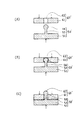
(4)図6は、雄部材50′と雌部材60′とを接合する接合構造の他の実施形態を示す断面視の説明図であり、図6(A)は、雌雄の部材60′,50′が接合される前の状態、図6(B)は、雌雄の部材60′,50′が接合されつつある状態。図6(C)は、雌雄の部材60′,50′が接合された状態をそれぞれ示している。
(4) FIG. 6 is an explanatory view in cross-sectional view showing another embodiment of the joint structure for joining the
この実施形態の接合構造においては、雄部材50′の雄側ブラケット51には、上記の片割れ突起521を有する係止用円柱体52に代えて、雄側ブラケット51に立設された括れ軸53と、この括れ軸53の先端に同心で付設された球体54とが設けられている。
In the joint structure of this embodiment, the
括れ軸53は、径寸法が雌側ブラケット61の嵌合孔62の孔径寸法より若干小さめに設定されているのに対し、球体54の径寸法は、嵌合孔62の径寸法より僅かに大きめに設定されている。
The diameter of the constricted
また、括れ軸53の長さ寸法は、雄側ブラケット51の厚み寸法より若干短めに設定されている。さらに、雌側ブラケット61には、抜け止め片63が設けられていない。
Further, the length dimension of the constricted
かかる構成の接合構造によれば、図6(A)に示すように、球体54を嵌合孔62に対向させた状態で、雄部材50′および雌部材60′に矢印で示すような力を加える。
According to the joining structure having such a configuration, as shown in FIG. 6A, in the state where the
そうすると、図6(B)に示すように、球体54が嵌合孔62の孔壁を弾性半径させながら当該嵌合孔62内に圧入されていく。
Then, as shown in FIG. 6B, the
そして、図6(C)に示すように、球体54が嵌合孔62から抜け出たときには、球体54の周面が嵌合孔62の孔縁と干渉した状態になるため、雌雄の部材60′,50′は、外れ止め状態で互いに接合される。この接合を解除するときは、矢印と反対方向に向けて雌雄の部材60′,50′に力を加え、両者を引き剥がせばよい。
Then, as shown in FIG. 6C, when the
このような接合構造において、括れ軸53の長さ寸法と球体54の半径との合計寸法は、雌側ブラケット61の厚み寸法より若干短めに設定され、これによって球体54が嵌合孔62から抜け出たとき、嵌合孔62の孔縁が弾性変形しない状態で球体54が孔縁に当接するようになされている。
In such a joint structure, the total dimension of the length dimension of the constricted
しかし、こうする代わりに、前記の合計寸法を雌側ブラケット61の厚み寸法より相当短くすると、球体54が嵌合孔62から抜け出た状態で、当該球体54の周面が嵌合孔62の孔縁を弾性変形させたままの状態になるため、この弾性力で雌雄の部材60′,50′は密着し、これによって両者がガタつくような不都合の発生を防止することができる。
However, instead of doing this, if the total dimension is considerably shorter than the thickness dimension of the
10 巻き付け具(被処理物) 20 平板状部材
21 長孔 22 帯状縁部
221 係止ピン 222 角孔
23 段差縁部 231 円孔
232 係止突起 30 針状体
40 接合手段 50,50′ 雄部材
51 雄側ブラケット 52 係止用円柱体(係止用突起)
521 片割れ突起 522 返し部
523 割れ溝 60,60′ 雌部材
61 雌側ブラケット 62 嵌合孔
63 抜け止め片 70,70′ 接合処理用工具
71 工具本体 72 把持桿(把持部)
73 操作部 74 連結軸
75,75′ 押圧板 76,76′ 雄部材押圧板
761 押し込み突起(突片(第1押圧部))
77,77′ 雌部材押圧板
771 逃がし溝 772,772′ 押圧条(第2押圧部)
L 電線(長尺物(被巻き付け物)))
DESCRIPTION OF
521 One
73
75, 75 '
77, 77 'Female
L electric wire (long object (object to be wrapped)))
Claims (5)
所定の被処理物における係止用突起が突設された雄部材と、前記係止用突起が係止状態で嵌入される嵌合孔が穿設された雌部材とが前記一方および他方の操作部にそれぞれ押圧挟持され得るように構成された接合処理用工具において、
前記一方の操作部には、前記他方の操作部との対向面に雄部材押圧板が設けられ、
前記他方の操作部には、前記一方の操作部との対向面に雌部材押圧板が設けられ、
前記雄部材押圧板には、前記雄部材を押圧するべく突設された1つの第1押圧部が設けられ、
前記雌部材押圧板には、前記雌部材を押圧するべく突設された2つの第2押圧部が設けられ、
前記雌雄の部材が、前記1つの第1押圧部と前記2つの第2押圧部とによる3点の押圧処理によって互いに外れ止めされるように構成されていることを特徴とする接合処理用工具。 A pair of gripping portions for gripping and a pair of operation portions extending from the tip of each gripping portion are provided, and a boundary position between the gripping portion and the operation portion can be rotated around a connecting shaft. Connected,
The male member provided with a locking projection in a predetermined object to be processed and the female member provided with a fitting hole into which the locking projection is fitted in the locked state are operated in the one and the other. In the joining processing tool configured to be able to be pressed and clamped to each part,
The one operation part is provided with a male member pressing plate on the surface facing the other operation part,
In the other operation part, a female member pressing plate is provided on the surface facing the one operation part,
The male member pressing plate is provided with one first pressing portion projecting to press the male member,
The female member pressing plate is provided with two second pressing portions projecting to press the female member,
The joint processing tool, wherein the male and female members are configured to be prevented from being separated from each other by a three-point pressing process by the one first pressing portion and the two second pressing portions.
前記第1押圧部と、前記第2押圧部とによる押圧挟持で前記雄部材の係止用突起を前記雌部材の嵌合孔に嵌め込ませるように構成されていることを特徴とする請求項1記載の接合処理用工具。 In a state where the first pressing portion is made to correspond to the locking projection of the male member, the two second pressing portions are arranged so as to face a substantially left and right target position with reference to the fitting hole of the female member. And the installation position of the second pressing part is set,
2. The structure according to claim 1, wherein the male member locking protrusion is fitted into the fitting hole of the female member by pressing and holding the first pressing portion and the second pressing portion. The joining tool described.
前記第2押圧部は、前記嵌合孔を横断し、前記一対の片割れ突起の間に嵌り込むように先端を自由端とした抜け止め片を設けた雌部材を、前記抜け止め片の側から押圧するように構成されていることを特徴とする請求項2記載の接合処理工具。 The first pressing portion presses a male member formed in a forked shape by a pair of one-sided split projections from the base end side of the one-sided split projection,
The second pressing portion has a female member provided with a retaining piece having a free end as a free end so as to be fitted between the pair of one-side split protrusions across the fitting hole from the retaining piece side. It is comprised so that it may press, The joining processing tool of Claim 2 characterized by the above-mentioned.
Priority Applications (1)
| Application Number | Priority Date | Filing Date | Title |
|---|---|---|---|
| JP2010010379A JP5279736B2 (en) | 2010-01-20 | 2010-01-20 | Joining processing tool |
Applications Claiming Priority (1)
| Application Number | Priority Date | Filing Date | Title |
|---|---|---|---|
| JP2010010379A JP5279736B2 (en) | 2010-01-20 | 2010-01-20 | Joining processing tool |
Publications (2)
| Publication Number | Publication Date |
|---|---|
| JP2011151925A true JP2011151925A (en) | 2011-08-04 |
| JP5279736B2 JP5279736B2 (en) | 2013-09-04 |
Family
ID=44538401
Family Applications (1)
| Application Number | Title | Priority Date | Filing Date |
|---|---|---|---|
| JP2010010379A Expired - Fee Related JP5279736B2 (en) | 2010-01-20 | 2010-01-20 | Joining processing tool |
Country Status (1)
| Country | Link |
|---|---|
| JP (1) | JP5279736B2 (en) |
Citations (4)
| Publication number | Priority date | Publication date | Assignee | Title |
|---|---|---|---|---|
| JPS6078274U (en) * | 1983-10-31 | 1985-05-31 | 高月 知和 | Removal tools such as piston cups |
| JPH02116020U (en) * | 1989-03-03 | 1990-09-17 | ||
| JPH09225843A (en) * | 1996-02-21 | 1997-09-02 | Nippon Telegr & Teleph Corp <Ntt> | Plier for protecting cover |
| JP2002165345A (en) * | 2000-11-27 | 2002-06-07 | Meishin Denki Kk | Anchor cover for wire and auxiliary anchor cover for the wire |
-
2010
- 2010-01-20 JP JP2010010379A patent/JP5279736B2/en not_active Expired - Fee Related
Patent Citations (4)
| Publication number | Priority date | Publication date | Assignee | Title |
|---|---|---|---|---|
| JPS6078274U (en) * | 1983-10-31 | 1985-05-31 | 高月 知和 | Removal tools such as piston cups |
| JPH02116020U (en) * | 1989-03-03 | 1990-09-17 | ||
| JPH09225843A (en) * | 1996-02-21 | 1997-09-02 | Nippon Telegr & Teleph Corp <Ntt> | Plier for protecting cover |
| JP2002165345A (en) * | 2000-11-27 | 2002-06-07 | Meishin Denki Kk | Anchor cover for wire and auxiliary anchor cover for the wire |
Also Published As
| Publication number | Publication date |
|---|---|
| JP5279736B2 (en) | 2013-09-04 |
Similar Documents
| Publication | Publication Date | Title |
|---|---|---|
| KR101303490B1 (en) | Connector and jig for connector | |
| AU2013321858A1 (en) | Wire gripper | |
| JP2012125854A (en) | Sleeve removal tool and sleeve removal method | |
| JP6148841B2 (en) | Washer | |
| JP2014093299A (en) | Locator and wire stopper device, manual crimping tool, method of disposing and holding connector, and system | |
| JP5279736B2 (en) | Joining processing tool | |
| TWI616041B (en) | Aluminum wire connection structure | |
| JP6778953B2 (en) | Profile connector | |
| JP2004204376A (en) | End part cover of string-like or belt-like material | |
| JP6781520B2 (en) | Cable sheath fixing spacer and cable fixture | |
| KR101229584B1 (en) | Hose clamp | |
| JP5431119B2 (en) | Underline connector | |
| KR200489557Y1 (en) | Insertion Tool for Connector Blocking Pin | |
| JP4461065B2 (en) | Bushing removal jig | |
| JP4363466B2 (en) | Safety band for binding band and binding band with safety block | |
| KR20120071480A (en) | Hair band | |
| JP4478957B2 (en) | Fishing weight fittings | |
| JP2009034805A (en) | Split ring pliers | |
| JP3241325U (en) | E-shaped retaining ring insertion tool | |
| JP5846968B2 (en) | Wire gripping collar | |
| JP2017185608A (en) | Hose clamp releasing tool | |
| JP2009054498A (en) | Come-off prevention member, come-off prevention mechanism using the same, and programmable display having the same | |
| JP4100408B2 (en) | Coaxial cable caulking ring | |
| JP2014230395A (en) | Work supporting tool | |
| JP4463161B2 (en) | Insulation cover for distribution line |
Legal Events
| Date | Code | Title | Description |
|---|---|---|---|
| A977 | Report on retrieval |
Free format text: JAPANESE INTERMEDIATE CODE: A971007 Effective date: 20120427 |
|
| A131 | Notification of reasons for refusal |
Free format text: JAPANESE INTERMEDIATE CODE: A131 Effective date: 20120914 |
|
| A521 | Written amendment |
Free format text: JAPANESE INTERMEDIATE CODE: A523 Effective date: 20121107 |
|
| TRDD | Decision of grant or rejection written | ||
| A01 | Written decision to grant a patent or to grant a registration (utility model) |
Free format text: JAPANESE INTERMEDIATE CODE: A01 Effective date: 20130510 |
|
| A61 | First payment of annual fees (during grant procedure) |
Free format text: JAPANESE INTERMEDIATE CODE: A61 Effective date: 20130521 |
|
| R150 | Certificate of patent or registration of utility model |
Free format text: JAPANESE INTERMEDIATE CODE: R150 Ref document number: 5279736 Country of ref document: JP Free format text: JAPANESE INTERMEDIATE CODE: R150 |
|
| R250 | Receipt of annual fees |
Free format text: JAPANESE INTERMEDIATE CODE: R250 |
|
| R250 | Receipt of annual fees |
Free format text: JAPANESE INTERMEDIATE CODE: R250 |
|
| R250 | Receipt of annual fees |
Free format text: JAPANESE INTERMEDIATE CODE: R250 |
|
| LAPS | Cancellation because of no payment of annual fees |