JP2011140303A - Brake control device - Google Patents
Brake control device Download PDFInfo
- Publication number
- JP2011140303A JP2011140303A JP2011017931A JP2011017931A JP2011140303A JP 2011140303 A JP2011140303 A JP 2011140303A JP 2011017931 A JP2011017931 A JP 2011017931A JP 2011017931 A JP2011017931 A JP 2011017931A JP 2011140303 A JP2011140303 A JP 2011140303A
- Authority
- JP
- Japan
- Prior art keywords
- behavior
- signal
- brake
- pitch
- braking
- Prior art date
- Legal status (The legal status is an assumption and is not a legal conclusion. Google has not performed a legal analysis and makes no representation as to the accuracy of the status listed.)
- Pending
Links
Images


Abstract
Description
本発明は、車両に用いられて乗り心地や操縦安定性の確保を図るようにしたブレーキ制御装置に関する。 The present invention relates to a brake control device that is used in a vehicle to ensure riding comfort and handling stability.
車両の乗り心地や操縦安定性の確保を図る装置の一例として特許文献1に示すサスペンション制御装置がある。特許文献1に示すサスペンション制御装置は、車両の車体と車軸との間に設けられた減衰係数可変型のショックアブソーバと、車体の上下振動を検出する振動検出手段と、を備え、振動検出手段の検出結果に基づいてショックアブソーバを制御するようにしている。
As an example of a device for ensuring the ride comfort and steering stability of a vehicle, there is a suspension control device shown in
ところで、上記従来技術では、ショックアブソーバのストロークに一定の制約があり、これに伴い制御し得る車両の挙動抑制量も制限を受けることになる。このため、前記従来技術では、車両が、長波状路(道路を長手方向に切断したときに路面形状が、波長の長い大きな波形状を示す道路)のように大きな凹凸を有する道路を、高速で走行した場合、ショックアブソーバがフルストロークするようなことが起こり、この場合には、仮にピッチング制御を行なっても、ピッチ挙動の抑制を良好には果たすことができないというのが実情であった。
本発明は、上記事情に鑑みてなされたものであり、車輪に対する制動力を用いることにより、大きな車両挙動に際し、その挙動抑制を図ることができるブレーキ制御装置を提供することを目的とする。
By the way, in the said prior art, there exists a fixed restriction | limiting in the stroke of a shock absorber, and the behavioral suppression amount of the vehicle which can be controlled in connection with this is also restricted. For this reason, in the prior art, a vehicle can move a road having large irregularities such as a long wave road (a road surface having a large wave shape with a long wavelength when the road is cut in the longitudinal direction) at a high speed. When the vehicle travels, the shock absorber may make a full stroke. In this case, even if the pitching control is performed, the pitch behavior cannot be satisfactorily suppressed.
The present invention has been made in view of the above circumstances, and an object of the present invention is to provide a brake control device that can suppress the behavior of a large vehicle behavior by using a braking force applied to wheels.
請求項1記載のブレーキ制御装置に係る発明は、アクチュエータにより作動されて車両の車輪の制動を行なうブレーキ手段と、前記車両の車体の上下方向の挙動を検出する車体挙動検出手段と、該車体挙動検出手段の検出結果に応じて、前記アクチュエータを駆動させて前記ブレーキ手段を制御する制御手段と、を備えたことを特徴とする。
請求項2記載の発明は、請求項1記載のブレーキ制御装置において、前記車体挙動検出手段は、前記車両の車体のピッチ挙動を検出するピッチ挙動検出手段であることを特徴とする。
請求項3記載の発明は、請求項1または2に記載のブレーキ制御装置において、前記制御手段は、少なくとも前記車両の運転者がブレーキ操作を行っていないときに、前記車体挙動検出手段の検出結果に応じて前記アクチュエータを制御することを特徴とする。
According to the first aspect of the present invention, there is provided a brake control device that is actuated by an actuator to brake a vehicle wheel, a vehicle body behavior detection unit that detects a vertical behavior of the vehicle body of the vehicle, and the vehicle body behavior. Control means for controlling the brake means by driving the actuator according to the detection result of the detection means.
According to a second aspect of the present invention, in the brake control device according to the first aspect, the vehicle body behavior detecting means is a pitch behavior detecting means for detecting a pitch behavior of the vehicle body of the vehicle.
According to a third aspect of the present invention, in the brake control device according to the first or second aspect, the control means is a detection result of the vehicle body behavior detecting means when at least a driver of the vehicle is not performing a brake operation. The actuator is controlled according to the above.
請求項1から3に記載の発明によれば、車体の挙動に応じてブレーキ手段を制御して車輪が制動されるので、制動力が作用される車輪の位置に応じた車体の荷重移動が発生し、この分、車体の挙動の抑制を図ることができる。
請求項2記載の発明によれば、ピッチ挙動の抑制を図ることができる。
According to the first to third aspects of the invention, since the wheel is braked by controlling the brake means according to the behavior of the vehicle body, the load movement of the vehicle body is generated according to the position of the wheel to which the braking force is applied. However, the behavior of the vehicle body can be suppressed accordingly.
According to invention of
以下、本発明の第1実施の形態に係るブレーキ制御装置1を図1ないし図3に基づいて説明する。
図1及び図2において、自動車2(車両)を構成する車体3(ばね上)と4個の車輪4側〔ばね下部材(車軸のショックアブソーバ取付けブラケット等)〕(ばね下)との間には、ばね5と、減衰特性を調整可能なショックアブソーバ6(減衰特性反転型ショックアブソーバ6)と、が並列に介装されており、これらが車体3を支持している。ショックアブソーバ6内には移動可能にピストン7が収納され、ピストン7に連結したピストンロッド8が車体3に保持され、ショックアブソーバ6が車輪4側〔ショックアブソーバ6取付けブラケット等〕に保持されている。
なお、図1には、車輪4は、左前輪(左前方の車輪4)、左後輪(左後方の車輪4)の2個のみ記載している。また、ショックアブソーバ6及びばね5は、4個の車輪4に対応してそれぞれ4個設けられているが、便宜上そのうち自動車の前後の2個のみを図示している。
Hereinafter, a
1 and 2, between the vehicle body 3 (sprung) constituting the automobile 2 (vehicle) and the four
In FIG. 1, only two
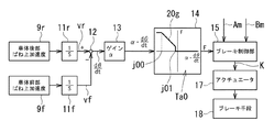
車体3の後部3rには、車体3の後部3rの上下加速度(車体後部ばね上加速度)を検出する後部加速度センサ9rが設けられている。車体3の前部3fには、車体3の前部3fの上下加速度(車体前部ばね上加速度)を検出する前部加速度センサ9fが設けられている。前部加速度センサ9f及び後部加速度センサ9rの間の距離(前後センサ間距離)は寸法Lに設定されている。後部加速度センサ9rには後部積分回路11rが接続されており、前部加速度センサ9fには前部積分回路11fが接続されている。後部積分回路11rは後部加速度センサ9rからの車体後部ばね上加速度を積分して、後部上下速度vrを得る。前部積分回路11fは、前部加速度センサ9fからの車体前部ばね上加速度を積分して、前部上下速度vfを得る。
The rear portion 3r of the vehicle body 3 is provided with a
前部積分回路11f及び後部積分回路11rには、前部、後部加速度センサ9f,9r及び前部、後部積分回路11f,11rと共にピッチ角速度検出手段を構成するピッチ角速度算出回路12が接続されている。ピッチ角速度算出回路12は、後部上下速度vrから前部上下速度vfを減算して、速度差(vr−vf)を求め、前後センサ間距離Lを用いて、(1)式によりピッチ角速度dθ/dtを求める。
dθ/dt=tan−1〔(vr−vf)/L〕 … (1)
Connected to the
dθ / dt = tan −1 [(vr−vf) / L] (1)
ピッチ角速度算出回路12には、増幅回路13が接続されている。増幅回路13は、ピッチ角速度dθ/dtにゲインαを乗算して、挙動制御用制動信号Fを算出するためのピッチ角速度(以下、便宜上、変形ピッチ角速度という。)α・dθ/dtを得るようにしている。
増幅回路13には、挙動制御用制動信号算出回路14が接続されている。挙動制御用制動信号算出回路14は、変形ピッチ角速度α・dθ/dtの入力を受け、これを挙動制御用制動信号F及び変形ピッチ角速度α・dθ/dtの対応関係を示す挙動制御用制動信号算出テーブルTa0に適用して挙動制御用制動信号Fを得るようにしている。
An
A behavior control braking
挙動制御用制動信号算出回路14には、ブレーキ制御部15と、アクチュエータ17と、アクチュエータ17に作動されて制動力を発生して各車輪4を制動させるブレーキ手段19とが、この順に設けられている。ブレーキ制御部15は、前記挙動制御用制動信号F及び後述する信号の入力を受け、これら信号から一つの信号を選択し,選択した信号を目標制動力信号Kとしてアクチュエータ17に入力する。アクチュエータ17は、入力を受けた目標制動力信号Kに基づいてブレーキ手段19を作動させる。
ブレーキ制御部15には、挙動制御用制動信号Fの他に、運転者のブレーキ操作に基づいて得られるブレーキ手段19作動用の制動操作命令信号Amと、図示しない車体挙動安定装置から出力される、ブレーキ手段19作動用の挙動安定化用制動信号Bmとが入力される。
The behavior control braking
In addition to the behavior control braking signal F, the
挙動制御用制動信号F、制動操作命令信号Am及び挙動安定化用制動信号Bmは、ブレーキ制御部15に選択され、選択された信号が目標制動力信号Kとしてアクチュエータ17に出力されて、ブレーキ手段19の制動力発生のために用いられる。各信号F、Am、Bmには、ブレーキ手段19が発生する制動力を示す要求内容が含まれている。ブレーキ制御部15による各信号F、Am、Bmの選択は、各信号F、Am、Bmが含んでいる要求内容(ブレーキ手段19が発生する制動力)に基づいて行なわれる。
The behavior control braking signal F, the braking operation command signal Am, and the behavior stabilization braking signal Bm are selected by the
挙動制御用制動信号算出テーブルTa0は、図2の挙動制御用制動信号算出回路14を示す矩形の枠内に記載されているように、変形ピッチ角速度α・dθ/dtを横軸にとり、挙動制御用制動信号Fを縦軸にとり、両者の対応関係を示す線分(以下、挙動制御用制動信号算出用線分20gという。)を含むグラフで構成されている。前記ピッチ角速度dθ/dtに比例する変形ピッチ角速度α・dθ/dtは、車体3の前部3fが下がった状態で正の値(前部3fが上がった状態で負の値)になるように設定されている。そして、図2のテーブルTa0において、横軸における縦軸より右側部分で変形ピッチ角速度α・dθ/dtは正であり、横軸における縦軸より左側部分では変形ピッチ角速度α・dθ/dtは負の値を示すように作成されている。
In the behavior control braking signal calculation table Ta0, as described in the rectangular frame showing the behavior control braking
挙動制御用制動信号算出用線分20gは、変形ピッチ角速度α・dθ/dtが正の値(図2で縦軸より右側)の場合、及び負の値でも所定値j01(負の値)より大きい場合には、挙動制御用制動信号Fの値が「0」となる(不感帯となる)ようにされている。挙動制御用制動信号算出用線分20gは、変形ピッチ角速度α・dθ/dtが所定値j01以下の場合は、その値が小さくなるに従って挙動制御用制動信号Fの値が大きくなり、変形ピッチ角速度α・dθ/dtが前記所定値j01より小さい一定値j00〔j00<j01〕より小さくなると、挙動制御用制動信号Fの値が一定の値となるようにされている。挙動制御用制動信号Fの値は、ブレーキ手段19が発生する制動力の大きさに対応している。
The behavior control braking
上述したように挙動制御用制動信号算出テーブルTa0は、変形ピッチ角速度α・dθ/dtが所定値j01より大きい場合は不感帯とされる。また、不感帯を除く所定値j01以下のときに、目標制動力信号Kとしてアクチュエータ17に出力される挙動制御用制動信号Fがブレーキ手段19の制動力発生に寄与することになる。
As described above, the behavior control braking signal calculation table Ta0 is a dead zone when the deformation pitch angular velocity α · dθ / dt is greater than the predetermined value j01. Further, the behavior control braking signal F output to the
制動操作命令信号Amがアクチュエータ17に入力されると、アクチュエータ17は、ブレーキ手段19を作動し、制動操作命令信号Amが含む要求内容に応じた大きさの制動力をブレーキ手段19に発生させる。挙動安定化用制動信号Bmがアクチュエータ17に入力されると、アクチュエータ17は、ブレーキ手段19を作動し、挙動安定化用制動信号Bmが含む要求内容に応じた大きさの制動力をブレーキ手段19に発生させる。
When the braking operation command signal Am is input to the
ブレーキ制御部15は、制動操作命令信号Am、挙動安定化用制動信号Bm、及び挙動制御用制動信号Fのうち、要求する制動力が最も大きい信号を、目標制動力信号Kとしてアクチュエータ17に出力する。例えば、挙動制御用制動信号Fの入力を受けているものの、制動操作命令信号Am及び挙動安定化用制動信号Bmの入力を受けていない場合には、ブレーキ制御部15は、挙動制御用制動信号Fをブレーキ手段19の作動のために用いるように目標制動力信号Kとしてアクチュエータ17に出力する。また、ブレーキ制御部15は、制動操作命令信号Am、挙動安定化用制動信号Bm及び挙動制御用制動信号Fのうち少なくとも2つの信号の入力を受けた場合、そのうち要求する制動力が最大である信号が目標制動力信号Kとしてアクチュエータ17に出力される。
前記前部積分回路11f、後部積分回路11r、ピッチ角速度算出回路12、増幅回路13、挙動制御用制動信号算出回路14及びブレーキ制御部15によりコントローラ20(制御手段)が構成されている。
The
The
上述したように構成されたブレーキ制御装置1の作用を、図3のフローチャートに基づいて説明する。
コントローラ20は、図3に示すように自動車2のエンジン(図示省略)の始動等により電力供給を受ける(ステップS1)と、まず初期設定を行なって(ステップS2)制御周期に達したか否かを判定する(ステップS3)。ステップS3では、制御周期に達したと判定するまで繰り返して制御周期に達したか否かを判定する。
The operation of the
As shown in FIG. 3, when the
ステップS3で制御周期に達したと判定すると、制動操作命令信号Am、挙動安定化用制動信号Bm及び挙動制御用制動信号Fのうち、各信号が要求する制動力が最大である信号が目標制動力信号Kとしてアクチュエータ17に入力されアクチュエータ17が駆動される(ステップS4)。このステップS4では、制動操作命令信号Am、挙動安定化用制動信号Bm及び挙動制御用制動信号Fについては、前回の制御周期で得られた信号(後述するステップS6、 S7)が用いられる。
If it is determined in step S3 that the control cycle has been reached, among the braking operation command signal Am, the behavior stabilization braking signal Bm, and the behavior control braking signal F, the signal for which the braking force required by each signal is maximum is the target control. The power signal K is input to the
続いて、LEDなどのその他のポートに対応する信号を出力する(ステップS5)。続いてステップS6で前部、後部加速度センサ9f,9rなどから検出信号を読込む(ステップS6)。ステップS6で前記制動操作命令信号Am及び挙動安定化用制動信号Bmを含む信号が入力され、次の制御周期のステップS4で用いられる。
Subsequently, a signal corresponding to another port such as an LED is output (step S5). Subsequently, in step S6, detection signals are read from the front and
次に、車体前部ばね上加速度及び車体後部ばね上加速度に基づいて、ピッチ角速度dθ/dt及び変形ピッチ角速度α・dθ/dtを求め、変形ピッチ角速度α・dθ/dtを挙動制御用制動信号算出テーブルTa0に適用して挙動制御用制動信号Fを求める(ステップS7)。この挙動制御用制動信号Fは、次の制御周期のステップS4で用いられる。 Next, the pitch angular velocity dθ / dt and the deformation pitch angular velocity α · dθ / dt are obtained based on the vehicle body front spring acceleration and the vehicle rear spring acceleration, and the deformation pitch angular velocity α · dθ / dt is determined as a braking signal for behavior control. The behavior control braking signal F is obtained by applying the calculation table Ta0 (step S7). This behavior control braking signal F is used in step S4 of the next control cycle.
そして、自動車2の走行時に、車体3の前部3fが上がり(テーブルTaでは変形ピッチ角速度α・dθ/dtが負の領域)、すなわち、車体3が図1時計方向にピッチ挙動することにより、ステップS7でこのピッチ挙動に応じた挙動制御用制動信号Fが得られる。ステップS7で得られた挙動制御用制動信号Fが要求する制動力が、ステップS6で得られた制動操作命令信号Am及び挙動安定化用制動信号Bmがそれぞれ要求する制動力より大きい場合、当該ステップS7で得られた挙動制御用制動信号Fは、次の制御周期のステップS4で前輪用のアクチュエータ17に目標制動力信号Kとして入力され、前輪用のブレーキ手段19が挙動制御用制動信号Fに応じた制動力を発生する。これにより、車体3には前方方向の荷重移動が生じ、車体3の図1時計方向のピッチ挙動を抑制する。
When the
本実施の形態では、車体3の前部3fが上がるピッチ挙動が所定レベルより大きくなる(変形ピッチ角速度α・dθ/dtの所定値J01以下になる)と、ピッチ運動を低減させる制御を行なう。そして、このピッチ運動の低減は、車輪4に制動力を作用させて行なうので、ピッチ運動の低減過程で車速も低減し、自動車2の走行を安定に維持しつつ行うことができる。
さらに、ピッチ運動の抑制を、ショックアブソーバ6の作動により行なうのではなく、車輪4を制動することにより行なうので、仮にショックアブソーバ6がフルストロークし、ショックアブソーバ6によってはピッチ運動の抑制が困難な状況となる大きなピッチ挙動にも対応でき、その大きなピッチ挙動の抑制を果たすことができる。
In the present embodiment, when the pitch behavior at which the front portion 3f of the vehicle body 3 rises becomes greater than a predetermined level (below a predetermined value J01 of the deformation pitch angular velocity α · dθ / dt), control is performed to reduce the pitch motion. Since the pitch motion is reduced by applying a braking force to the
Furthermore, since the pitch motion is not controlled by the operation of the
上記実施の形態では、挙動制御用制動信号Fを目標制動力信号Kとして前輪用のアクチュエータ17に入力し、前輪用のブレーキ手段19が制動力を発生する場合を例にしたが、これに代えて、挙動制御用制動信号Fを目標制動力信号Kとして前輪、後輪用のアクチュエータ17に入力し、前輪、後輪用のブレーキ手段19が制動力を発生するようにしてピッチ挙動を抑制するようにしてもよい。しかし、このように前輪、後輪用のブレーキ手段19に制動力を発生させる例に比して上記実施の形態とする(挙動制御用制動信号Fを前輪用のアクチュエータ17に入力し、前輪用のブレーキ手段19に制動力を発生させる。)ことにより、より大きなピッチ挙動を抑制でき、かつ車速については低減を抑制できる。
In the above embodiment, the behavior control braking signal F is input to the
次に、本発明の第2実施の形態に係るブレーキ制御装置1Aを図4に基づいて説明する。
第2実施の形態に係るブレーキ制御装置1Aは、第1実施の形態に係るブレーキ制御装置1に比して、下記(1)〜(5)の事項が主に異なっている。
(1)ブレーキ制御装置1が1つの挙動制御用制動信号算出回路14を設けているのに代えて、前輪用、後輪用挙動制御用制動信号算出回路14f,14rを設け、各検出結果に応じて、前輪、後輪用のブレーキ手段19をそれぞれ作動させるようにしたこと。
(2)ブレーキ制御部15に代わるブレーキ制御部15(以下、便宜上、第2ブレーキ制御部15Aという。)を設けたこと。
(3)第1実施の形態のコントローラ20に代わるコントローラ20Aを設けたこと。
(4)挙動制御用制動信号算出回路14が用いる挙動制御用制動信号算出テーブルTa0に代えて、前輪用挙動制御用制動信号算出回路14fが前輪用挙動制御用制動信号算出テーブルTafを用いたこと。
(5)テーブルTafでは、テーブルTa0の挙動制御用制動信号算出用線分20gに代えてこれと同等形状の前輪用挙動制御用制動信号算出用線分20fを用い、挙動制御用制動信号Fに代えて前輪用挙動制御用制動信号Ffを設け、かつ、挙動制御用制動信号算出回路14が挙動制御用制動信号Fを出力するのに代えて前輪用挙動制御用制動信号Ffを出力するようにしたこと。
Next, a
The
(1) Instead of providing one behavior control braking
(2) A brake control unit 15 (hereinafter referred to as a second
(3) A
(4) Instead of the behavior control braking signal calculation table Ta0 used by the behavior control braking
(5) In the table Taf, instead of the behavior control braking signal
なお、前輪用挙動制御用制動信号算出用線分20fは、上述したように挙動制御用制動信号算出用線分20gと同等形状であるが、所定値j01に対応する値については、便宜上、第1所定値j01(符号は同一とする。)という。
The front wheel behavior control braking signal
後輪用挙動制御用制動信号算出回路14rは、後輪用挙動制御用制動信号算出テーブルTarを用いて、後輪用挙動制御用制動信号Frを得てこれをブレーキ制御部15に出力する。後輪用挙動制御用制動信号算出テーブルTarは、前記テーブルTafの前輪用挙動制御用制動信号算出用線分20fとは異なる形状の後輪用挙動制御用制動信号20rを有している。
前記テーブルTarの後輪用挙動制御用制動信号20rは、変形ピッチ角速度α・dθ/dtが負の値(図4で縦軸より左側)の場合、及び正の値でも所定値(以下、第2所定値j02という。)より小さい場合には、後輪用挙動制御用制動信号Frが「0」となる(不感帯となる)ようにされている。また、後輪用挙動制御用制動信号20rは、変形ピッチ角速度α・dθ/dtが第2所定値j02以上の場合は、その値が大きくなるに従って後輪用挙動制御用制動信号Frが大きくなるようにされている。
The rear wheel behavior control braking
The
第2ブレーキ制御部15Aは、後輪用のアクチュエータ17には、制動操作命令信号Am、挙動安定化用制動信号Bm、及び後輪用挙動制御用制動信号Frのうち、要求する制動力が最も大きい信号を選択し、選択した信号を目標制動力信号Kとして出力する。また、前輪用のアクチュエータ17には、制動操作命令信号Am、挙動安定化用制動信号Bm、及び前輪用挙動制御用制動信号Ffのうち、要求する制動力が最も大きい信号を選択し、選択した信号を目標制動力信号Kとして出力する。
この第2実施の形態では、コントローラ20A(制御手段)は、前部積分回路11f、後部積分回路11r、ピッチ角速度算出回路12、増幅回路13、前輪用、後輪用挙動制御用制動信号算出回路14f,14r、及び第2ブレーキ制御部15Aから構成されている。
The second
In the second embodiment, the
上述した第2実施の形態では、変形ピッチ角速度α・dθ/dtが第1所定値j01以下のときに前輪用のブレーキ手段19が制動力を発生し、第2所定値j02以上のときに後輪用のブレーキ手段19が制動力を発生する。つまり、車体3前部が所定レベル以上に上昇する(車体3が図1時計方向のピッチ挙動を行なう。)と、前輪(前方側の車輪4)が制動され、車体3後部があるレベル以上に上昇する(車体3が図1反時計方向のピッチ挙動を行なう。)と、後輪(後方側の車輪4)が制動される。
上述したようにピッチ運動の抑制を、ショックアブソーバ6(図1参照)の作動により行なうのではなく、車輪4(図1参照)を制動することにより行なうので、仮にショックアブソーバ6がフルストロークし、ショックアブソーバ6によってはピッチ運動の抑制が困難な状況となる大きなピッチ挙動にも対応でき、その大きなピッチ挙動の抑制を果たすことができる。
In the second embodiment described above, the front wheel brake means 19 generates a braking force when the deformation pitch angular velocity α · dθ / dt is equal to or smaller than the first predetermined value j01, and the rearward when the deformation pitch angular velocity α · dθ / dt is equal to or larger than the second predetermined value j02. The wheel brake means 19 generates a braking force. That is, when the front part of the vehicle body 3 rises above a predetermined level (the vehicle body 3 performs the pitch behavior in the clockwise direction in FIG. 1), the front wheel (the front wheel 4) is braked and the rear part of the vehicle body 3 exceeds a certain level. Ascending (the vehicle body 3 performs a counterclockwise pitch behavior in FIG. 1), the rear wheels (rear wheels 4) are braked.
As described above, the pitch motion is not controlled by the operation of the shock absorber 6 (see FIG. 1) but by braking the wheel 4 (see FIG. 1), so that the
上記第1、第2実施の形態において、アンチブレーキシステムの制御ロジックを加えるようにしてもよい。この場合、制動力は車輪4がロックしない範囲で制御されることになり、より良好な走行安定性を確保することができる。
In the first and second embodiments, an anti-brake system control logic may be added. In this case, the braking force is controlled within a range in which the
1,1A…ブレーキ制御装置、9f,9r…前部、後部加速度センサ(車体挙動検出手段)、11f,11r…前部、後部積分回路(車体挙動検出手段)、12…ピッチ角速度算出回路、17…アクチュエータ、19…ブレーキ手段、20,20A…コントローラ(制御手段)。
DESCRIPTION OF
Claims (3)
前記車両の車体の上下方向の挙動を検出する車体挙動検出手段と、
該車体挙動検出手段の検出結果に応じて、前記アクチュエータを駆動させて前記ブレーキ手段を制御する制御手段と、を備えたことを特徴とするブレーキ制御装置。 Brake means actuated by an actuator to brake the wheels of the vehicle;
Vehicle body behavior detection means for detecting the vertical behavior of the vehicle body;
A brake control device comprising: a control unit that controls the brake unit by driving the actuator in accordance with a detection result of the vehicle body behavior detection unit.
Priority Applications (1)
| Application Number | Priority Date | Filing Date | Title |
|---|---|---|---|
| JP2011017931A JP2011140303A (en) | 2011-01-31 | 2011-01-31 | Brake control device |
Applications Claiming Priority (1)
| Application Number | Priority Date | Filing Date | Title |
|---|---|---|---|
| JP2011017931A JP2011140303A (en) | 2011-01-31 | 2011-01-31 | Brake control device |
Related Parent Applications (1)
| Application Number | Title | Priority Date | Filing Date |
|---|---|---|---|
| JP2006022711A Division JP4858756B2 (en) | 2006-01-31 | 2006-01-31 | Brake control device |
Publications (2)
| Publication Number | Publication Date |
|---|---|
| JP2011140303A true JP2011140303A (en) | 2011-07-21 |
| JP2011140303A5 JP2011140303A5 (en) | 2012-06-21 |
Family
ID=44456471
Family Applications (1)
| Application Number | Title | Priority Date | Filing Date |
|---|---|---|---|
| JP2011017931A Pending JP2011140303A (en) | 2011-01-31 | 2011-01-31 | Brake control device |
Country Status (1)
| Country | Link |
|---|---|
| JP (1) | JP2011140303A (en) |
Cited By (3)
| Publication number | Priority date | Publication date | Assignee | Title |
|---|---|---|---|---|
| JP2013154801A (en) * | 2012-01-31 | 2013-08-15 | Nissan Motor Co Ltd | Control device of vehicle |
| EP3211261A1 (en) | 2016-02-01 | 2017-08-30 | Toyota Jidosha Kabushiki Kaisha | Vehicle, controller for vehicle, and control method for vehicle |
| KR20230166133A (en) | 2021-05-27 | 2023-12-06 | 히다치 아스테모 가부시키가이샤 | Brake control device and brake control method |
Citations (2)
| Publication number | Priority date | Publication date | Assignee | Title |
|---|---|---|---|---|
| JP2002029397A (en) * | 2000-07-12 | 2002-01-29 | Toyota Motor Corp | Braking force control device for vehicle |
| JP2005186936A (en) * | 2005-02-21 | 2005-07-14 | Toyota Motor Corp | Automatic braking control device of vehicle |
-
2011
- 2011-01-31 JP JP2011017931A patent/JP2011140303A/en active Pending
Patent Citations (2)
| Publication number | Priority date | Publication date | Assignee | Title |
|---|---|---|---|---|
| JP2002029397A (en) * | 2000-07-12 | 2002-01-29 | Toyota Motor Corp | Braking force control device for vehicle |
| JP2005186936A (en) * | 2005-02-21 | 2005-07-14 | Toyota Motor Corp | Automatic braking control device of vehicle |
Cited By (4)
| Publication number | Priority date | Publication date | Assignee | Title |
|---|---|---|---|---|
| JP2013154801A (en) * | 2012-01-31 | 2013-08-15 | Nissan Motor Co Ltd | Control device of vehicle |
| EP3211261A1 (en) | 2016-02-01 | 2017-08-30 | Toyota Jidosha Kabushiki Kaisha | Vehicle, controller for vehicle, and control method for vehicle |
| US10309467B2 (en) | 2016-02-01 | 2019-06-04 | Toyota Jidosha Kabushiki Kaisha | Vehicle, controller for vehicle, and control method for vehicle |
| KR20230166133A (en) | 2021-05-27 | 2023-12-06 | 히다치 아스테모 가부시키가이샤 | Brake control device and brake control method |
Similar Documents
| Publication | Publication Date | Title |
|---|---|---|
| KR101826356B1 (en) | Suspension control apparatus | |
| JP5809474B2 (en) | Body posture control device | |
| JP5809506B2 (en) | Vehicle motion control device and suspension control device | |
| JP5700190B2 (en) | Suspension control device | |
| US9120469B2 (en) | Vehicle behavior control apparatus | |
| JP4858756B2 (en) | Brake control device | |
| CN104553666A (en) | Suspension system | |
| JP7275847B2 (en) | vehicle controller | |
| JP6638703B2 (en) | Suspension control system | |
| JP5398581B2 (en) | Suspension control device | |
| JP2011140303A (en) | Brake control device | |
| JP2007203831A (en) | Suspension control device | |
| JP2019151124A (en) | Suspension device and vehicle comprising the same | |
| JP2016104605A (en) | Control device of vehicle | |
| JP2015120398A (en) | Suspension control device | |
| US20220314725A1 (en) | Vehicle control device | |
| CN107168279B (en) | A kind of control method of the Vehicle Active Suspension System based on H ∞ preview control | |
| JP2008247357A (en) | Suspension control device | |
| JP2009061876A (en) | Stopping braking force control device | |
| KR20220034194A (en) | vehicle motion control | |
| JP4435303B2 (en) | Control device for damping force variable damper | |
| JP2009196504A (en) | Suspension control device | |
| JP2007153187A (en) | Control system for variable damping force damper | |
| WO2023048085A1 (en) | Vehicle control device and vehicle control system | |
| JP2010052488A (en) | Suspension control device |
Legal Events
| Date | Code | Title | Description |
|---|---|---|---|
| A621 | Written request for application examination |
Free format text: JAPANESE INTERMEDIATE CODE: A621 Effective date: 20110302 |
|
| A521 | Written amendment |
Free format text: JAPANESE INTERMEDIATE CODE: A523 Effective date: 20120425 |
|
| A977 | Report on retrieval |
Free format text: JAPANESE INTERMEDIATE CODE: A971007 Effective date: 20120913 |
|
| A131 | Notification of reasons for refusal |
Free format text: JAPANESE INTERMEDIATE CODE: A131 Effective date: 20120919 |
|
| A521 | Written amendment |
Free format text: JAPANESE INTERMEDIATE CODE: A523 Effective date: 20121116 |
|
| A02 | Decision of refusal |
Free format text: JAPANESE INTERMEDIATE CODE: A02 Effective date: 20121219 |