JP2011136865A - Reformer, reforming unit, and fuel cell system - Google Patents

Reformer, reforming unit, and fuel cell system Download PDF

Info

Publication number
JP2011136865A
JP2011136865A JP2009298203A JP2009298203A JP2011136865A JP 2011136865 A JP2011136865 A JP 2011136865A JP 2009298203 A JP2009298203 A JP 2009298203A JP 2009298203 A JP2009298203 A JP 2009298203A JP 2011136865 A JP2011136865 A JP 2011136865A
Authority
JP
Japan
Prior art keywords
reformer
peripheral surface
gas
cylindrical
reforming
Prior art date
Legal status (The legal status is an assumption and is not a legal conclusion. Google has not performed a legal analysis and makes no representation as to the accuracy of the status listed.)
Pending
Application number
JP2009298203A
Other languages
Japanese (ja)
Inventor
Kazuyuki Tono
和志 東野
Koichi Sato
光一 佐藤
Kei Saito
圭 齋藤
Current Assignee (The listed assignees may be inaccurate. Google has not performed a legal analysis and makes no representation or warranty as to the accuracy of the list.)
Idemitsu Kosan Co Ltd
Corona Corp
Original Assignee
Idemitsu Kosan Co Ltd
Corona Corp
Priority date (The priority date is an assumption and is not a legal conclusion. Google has not performed a legal analysis and makes no representation as to the accuracy of the date listed.)
Filing date
Publication date
Application filed by Idemitsu Kosan Co Ltd, Corona Corp filed Critical Idemitsu Kosan Co Ltd
Priority to JP2009298203A priority Critical patent/JP2011136865A/en
Priority to TW099146020A priority patent/TW201137110A/en
Priority to PCT/JP2010/073350 priority patent/WO2011081092A1/en
Publication of JP2011136865A publication Critical patent/JP2011136865A/en
Pending legal-status Critical Current

Links

Images

Classifications

    • HELECTRICITY
    • H01ELECTRIC ELEMENTS
    • H01MPROCESSES OR MEANS, e.g. BATTERIES, FOR THE DIRECT CONVERSION OF CHEMICAL ENERGY INTO ELECTRICAL ENERGY
    • H01M8/00Fuel cells; Manufacture thereof
    • H01M8/06Combination of fuel cells with means for production of reactants or for treatment of residues
    • H01M8/0606Combination of fuel cells with means for production of reactants or for treatment of residues with means for production of gaseous reactants
    • H01M8/0612Combination of fuel cells with means for production of reactants or for treatment of residues with means for production of gaseous reactants from carbon-containing material
    • CCHEMISTRY; METALLURGY
    • C01INORGANIC CHEMISTRY
    • C01BNON-METALLIC ELEMENTS; COMPOUNDS THEREOF; METALLOIDS OR COMPOUNDS THEREOF NOT COVERED BY SUBCLASS C01C
    • C01B3/00Hydrogen; Gaseous mixtures containing hydrogen; Separation of hydrogen from mixtures containing it; Purification of hydrogen
    • C01B3/02Production of hydrogen or of gaseous mixtures containing a substantial proportion of hydrogen
    • C01B3/32Production of hydrogen or of gaseous mixtures containing a substantial proportion of hydrogen by reaction of gaseous or liquid organic compounds with gasifying agents, e.g. water, carbon dioxide, air
    • C01B3/34Production of hydrogen or of gaseous mixtures containing a substantial proportion of hydrogen by reaction of gaseous or liquid organic compounds with gasifying agents, e.g. water, carbon dioxide, air by reaction of hydrocarbons with gasifying agents
    • C01B3/38Production of hydrogen or of gaseous mixtures containing a substantial proportion of hydrogen by reaction of gaseous or liquid organic compounds with gasifying agents, e.g. water, carbon dioxide, air by reaction of hydrocarbons with gasifying agents using catalysts
    • C01B3/384Production of hydrogen or of gaseous mixtures containing a substantial proportion of hydrogen by reaction of gaseous or liquid organic compounds with gasifying agents, e.g. water, carbon dioxide, air by reaction of hydrocarbons with gasifying agents using catalysts the catalyst being continuously externally heated
    • HELECTRICITY
    • H01ELECTRIC ELEMENTS
    • H01MPROCESSES OR MEANS, e.g. BATTERIES, FOR THE DIRECT CONVERSION OF CHEMICAL ENERGY INTO ELECTRICAL ENERGY
    • H01M8/00Fuel cells; Manufacture thereof
    • H01M8/06Combination of fuel cells with means for production of reactants or for treatment of residues
    • H01M8/0606Combination of fuel cells with means for production of reactants or for treatment of residues with means for production of gaseous reactants
    • H01M8/0612Combination of fuel cells with means for production of reactants or for treatment of residues with means for production of gaseous reactants from carbon-containing material
    • H01M8/0618Reforming processes, e.g. autothermal, partial oxidation or steam reforming
    • HELECTRICITY
    • H01ELECTRIC ELEMENTS
    • H01MPROCESSES OR MEANS, e.g. BATTERIES, FOR THE DIRECT CONVERSION OF CHEMICAL ENERGY INTO ELECTRICAL ENERGY
    • H01M8/00Fuel cells; Manufacture thereof
    • H01M8/06Combination of fuel cells with means for production of reactants or for treatment of residues
    • H01M8/0606Combination of fuel cells with means for production of reactants or for treatment of residues with means for production of gaseous reactants
    • H01M8/0612Combination of fuel cells with means for production of reactants or for treatment of residues with means for production of gaseous reactants from carbon-containing material
    • H01M8/0625Combination of fuel cells with means for production of reactants or for treatment of residues with means for production of gaseous reactants from carbon-containing material in a modular combined reactor/fuel cell structure
    • H01M8/0631Reactor construction specially adapted for combination reactor/fuel cell
    • HELECTRICITY
    • H01ELECTRIC ELEMENTS
    • H01MPROCESSES OR MEANS, e.g. BATTERIES, FOR THE DIRECT CONVERSION OF CHEMICAL ENERGY INTO ELECTRICAL ENERGY
    • H01M8/00Fuel cells; Manufacture thereof
    • H01M8/06Combination of fuel cells with means for production of reactants or for treatment of residues
    • H01M8/0662Treatment of gaseous reactants or gaseous residues, e.g. cleaning
    • H01M8/0668Removal of carbon monoxide or carbon dioxide
    • HELECTRICITY
    • H01ELECTRIC ELEMENTS
    • H01MPROCESSES OR MEANS, e.g. BATTERIES, FOR THE DIRECT CONVERSION OF CHEMICAL ENERGY INTO ELECTRICAL ENERGY
    • H01M8/00Fuel cells; Manufacture thereof
    • H01M8/10Fuel cells with solid electrolytes
    • H01M2008/1095Fuel cells with polymeric electrolytes
    • YGENERAL TAGGING OF NEW TECHNOLOGICAL DEVELOPMENTS; GENERAL TAGGING OF CROSS-SECTIONAL TECHNOLOGIES SPANNING OVER SEVERAL SECTIONS OF THE IPC; TECHNICAL SUBJECTS COVERED BY FORMER USPC CROSS-REFERENCE ART COLLECTIONS [XRACs] AND DIGESTS
    • Y02TECHNOLOGIES OR APPLICATIONS FOR MITIGATION OR ADAPTATION AGAINST CLIMATE CHANGE
    • Y02EREDUCTION OF GREENHOUSE GAS [GHG] EMISSIONS, RELATED TO ENERGY GENERATION, TRANSMISSION OR DISTRIBUTION
    • Y02E60/00Enabling technologies; Technologies with a potential or indirect contribution to GHG emissions mitigation
    • Y02E60/30Hydrogen technology
    • Y02E60/50Fuel cells

Landscapes

  • Chemical & Material Sciences (AREA)
  • Chemical Kinetics & Catalysis (AREA)
  • Engineering & Computer Science (AREA)
  • General Chemical & Material Sciences (AREA)
  • Sustainable Energy (AREA)
  • Sustainable Development (AREA)
  • Manufacturing & Machinery (AREA)
  • Electrochemistry (AREA)
  • Life Sciences & Earth Sciences (AREA)
  • Organic Chemistry (AREA)
  • Health & Medical Sciences (AREA)
  • General Health & Medical Sciences (AREA)
  • Combustion & Propulsion (AREA)
  • Inorganic Chemistry (AREA)
  • Hydrogen, Water And Hydrids (AREA)
  • Fuel Cell (AREA)

Abstract

【課題】簡単な構造で、かつ、効率よく改質処理できる改質装置、改質ユニットおよび燃料電池システムを提供する。
【解決手段】本発明の改質装置620は、熱交換器640は、径の異なる筒状の第一筒部材642Aないし第三筒部材642Cを有し、第一筒部材642Aの外周面と第二筒部材642Bの内周面との間が改質器620の原料ガス入口に連通して原料ガスが流通され、第二筒部材642Bの外周面と第三筒部材642Cの内周面との間が改質器620の改質ガス出口に連通して改質ガスが流通される、若しくは、第一筒部材642Aの外周面と642B第二筒部材の内周面との間が改質器620の原料ガス入口に連通して改質ガスが流通され、第二筒部材642Bの外周面と第三筒部材642Cの内周面との間が改質器620の改質ガス出口に連通して原料ガスが流通される三重管構造に形成されたことを特徴とした。
【選択図】図4
A reforming apparatus, a reforming unit, and a fuel cell system that have a simple structure and that can be efficiently reformed are provided.
In a reformer 620 of the present invention, a heat exchanger 640 includes cylindrical first cylindrical members 642A to 642C having different diameters, and the outer peripheral surface of the first cylindrical member 642A and the first cylindrical member 642A. The space between the inner peripheral surface of the two cylinder members 642B communicates with the source gas inlet of the reformer 620 and the source gas is circulated, and the outer peripheral surface of the second cylindrical member 642B and the inner peripheral surface of the third cylindrical member 642C The reformed gas is circulated in communication with the reformed gas outlet of the reformer 620, or the reformer is between the outer peripheral surface of the first cylindrical member 642A and the inner peripheral surface of the 642B second cylindrical member. The reformed gas is circulated in communication with the source gas inlet of 620, and the space between the outer peripheral surface of the second cylindrical member 642B and the inner peripheral surface of the third cylindrical member 642C communicates with the reformed gas outlet of the reformer 620. Thus, it is characterized in that it is formed in a triple tube structure in which the source gas is circulated.
[Selection] Figure 4

Description

本発明は、炭化水素燃料を含有する原料ガスをバーナーの燃焼ガスにより加熱して水素ガスを含有する改質ガスを生成させる改質装置、改質ユニットおよびこの改質ユニットを備えた燃料電池システムに関する。   The present invention relates to a reforming apparatus, a reforming unit, and a fuel cell system including the reforming unit, wherein a raw material gas containing a hydrocarbon fuel is heated by a burner combustion gas to generate a reformed gas containing hydrogen gas. About.

従来、炭化水素原料を含有する原料ガスを水素ガスを含有する改質ガスに改質する各種改質装置が知られている(例えば、特許文献1〜3)。
特許文献1に記載のものは、改質触媒層の外側にCO変成触媒層を配置し、CO変成触媒層の外側にCO選択酸化触媒層を配置している。この改質器では、CO変成触媒層と原料ガスとの熱交換をすることにより熱効率を向上させる構成が採られている。
また、特許文献2に記載のものは、二重管熱交換器を活用し、外管に原料ガスを流通させて生成した改質ガスを内管から回収することで熱交換する構成が採られている。
さらに、特許文献3に記載のものは、触媒層を流通して生成した改質ガスをリターンさせて触媒層の外側を流通させることで熱交換する構成が採られている。
Conventionally, various reformers for reforming a raw material gas containing a hydrocarbon raw material into a reformed gas containing hydrogen gas are known (for example, Patent Documents 1 to 3).
In the device described in Patent Document 1, a CO shift catalyst layer is disposed outside the reforming catalyst layer, and a CO selective oxidation catalyst layer is disposed outside the CO shift catalyst layer. In this reformer, a configuration is adopted in which heat efficiency is improved by exchanging heat between the CO shift catalyst layer and the raw material gas.
Moreover, the thing of patent document 2 employ | adopted the structure which heat-exchanges by collect | recovering the reformed gas produced | generated by distribute | circulating raw material gas to an outer tube | pipe using the double tube | pipe heat exchanger from an inner tube | pipe. ing.
Furthermore, the thing of patent document 3 is taken as the structure which heat-exchanges by returning the reformed gas produced | generated by distribute | circulating a catalyst layer and distribute | circulating the outer side of a catalyst layer.

特許3808743号Japanese Patent No. 3808743 特開2008−189500号公報JP 2008-189500 A 特開2000−178004号公報JP 2000-178004 A

ところで、燃料電池システムでは、エネルギー効率が重要である。そして、燃料電池に供給する水素ガスを製造する工程において、改質の際の加熱は全工程中で比較的に大きなエネルギーを必要とする。このことにより、効率よく加熱して改質処理する必要がある。
このうち価格低減のため、簡略化によるコスト低減を図りつつ、効率の低下を抑制することが必要で有る。
By the way, in a fuel cell system, energy efficiency is important. In the process of producing hydrogen gas to be supplied to the fuel cell, the heating during the reforming requires a relatively large amount of energy during the entire process. For this reason, it is necessary to heat and reform the material efficiently.
Among these, in order to reduce the price, it is necessary to reduce the efficiency while reducing the cost by simplification.

具体的には、特許文献1の改質装置では、改質触媒層とCO変成触媒層の温度バランスの観点等より、改質触媒層とCO変成触媒層の間に断熱材等を設置し伝熱を抑制する必要があり、伝熱を抑制するための構成により、装置構築が煩雑となったり、装置が大型化したりするなどの不都合を生じるおそれがある。
また、特許文献2の改質装置では、複数の二重管が必要となり、更なる低コスト化を進めるには、より簡単な構造が望まれる。
さらに、簡単な構造としては、特許文献3の改質装置が挙げられるが、これだけでは、効率を向上させる上で十分な熱交換とは言いがたく、さらなる熱交換効率の向上が必要である。
Specifically, in the reformer of Patent Document 1, a heat insulating material or the like is installed between the reforming catalyst layer and the CO shift catalyst layer from the viewpoint of the temperature balance between the reforming catalyst layer and the CO shift catalyst layer. It is necessary to suppress heat, and the configuration for suppressing heat transfer may cause inconveniences such as complicated construction of the apparatus and an increase in the size of the apparatus.
Further, the reformer of Patent Document 2 requires a plurality of double pipes, and a simpler structure is desired for further cost reduction.
Furthermore, as a simple structure, the reformer of Patent Document 3 can be cited. However, it is difficult to say that heat exchange is sufficient for improving efficiency, and further improvement in heat exchange efficiency is necessary.

本発明の目的は、このような点に鑑みて、簡単な構造で、かつ、効率よく改質処理できる改質装置、改質ユニットおよび燃料電池システムを提供することにある。   An object of the present invention is to provide a reforming apparatus, a reforming unit, and a fuel cell system that can perform a reforming process efficiently with a simple structure in view of such points.

本発明に記載の改質装置は、炭化水素原料および水蒸気を含有する原料ガスを改質触媒中で加熱して改質ガスを生成させる改質器と、前記原料ガスと前記改質ガスとを熱交換する熱交換器と、を備えた改質装置であって、前記熱交換器は、筒状の第一筒部材と、この第一筒部材の外径より内径が径大の筒状で、前記第一筒部材の外周側に同軸上に配置された第二筒部材と、この第二筒部材の外径より内径が径大の筒状で、前記第二筒部材の外周側に同軸上に配置された第三筒部材と、を有し、前記第一筒部材の外周面と前記第二筒部材の内周面との間が前記改質器の前記原料ガスの入口に連通して前記原料ガスが流通され、前記第二筒部材の外周面と前記第三筒部材の内周面との間が前記改質器の前記改質ガスの出口に連通して前記改質ガスが流通される、若しくは、前記第一筒部材の外周面と前記第二筒部材の内周面との間が前記改質器の前記改質ガスの出口に連通して前記改質ガスが流通され、前記第二筒部材の外周面と前記第三筒部材の内周面との間が前記改質器の前記原料ガスの入口に連通して前記原料ガスが流通される三重管構造に形成されたことを特徴とした。   The reformer according to the present invention includes a reformer that generates a reformed gas by heating a feedstock gas containing a hydrocarbon feedstock and steam in a reforming catalyst, and the feedstock gas and the reformed gas. A heat exchanger for exchanging heat, wherein the heat exchanger has a cylindrical first cylindrical member and a cylindrical shape whose inner diameter is larger than the outer diameter of the first cylindrical member. A second cylindrical member coaxially disposed on the outer peripheral side of the first cylindrical member, and a cylindrical shape having an inner diameter larger than the outer diameter of the second cylindrical member, and coaxial on the outer peripheral side of the second cylindrical member A third cylindrical member disposed above, and a space between the outer peripheral surface of the first cylindrical member and the inner peripheral surface of the second cylindrical member communicates with the raw material gas inlet of the reformer. The raw material gas is circulated, and the reformed gas is communicated between the outer peripheral surface of the second cylinder member and the inner peripheral surface of the third cylinder member with the reformed gas outlet of the reformer. The reformed gas is circulated between the outer peripheral surface of the first cylindrical member and the inner peripheral surface of the second cylindrical member in communication with the reformed gas outlet of the reformer. The triple pipe structure in which the raw material gas is circulated between the outer peripheral surface of the second cylindrical member and the inner peripheral surface of the third cylindrical member communicates with the raw material gas inlet of the reformer. It was characterized by that.

そして、本発明では、前記第一筒部材と前記第二筒部材との間および前記第二筒部材と前記第三筒部材との間は、0.1mm以上10mm以下である構成とすることが好ましい。
また、本発明では、前記第一筒部材の外周面と前記第三筒部材の内周面とに、または、前記第二筒部材の内周面と前記第三筒部材の内周面とに、あるいは、前記第一筒部材の外周面と前記第二筒部材の外周面とのいずれかに凸部が形成され、前記凸部の頂部が前記第一筒部材ないし前記第三筒部材の内周面若しくは外周面の少なくともいずれか一方に当接した構成とすることが好ましい。
さらに、本発明では、前記第二筒部材は、内周面において内側に突出した突出部を有し、前記突出部は、前記第一筒部材の開口端部を支持した構成とすることが好ましい。
そして、本発明では、前記第一筒部材は、下側に開口した略コップ状に形成され、前記第二筒部材は、上側に開口した略コップ状に形成された構成とすることが好ましい。
さらに、本発明では、前記改質器は、内周側が燃焼器により加熱される筒状の第一改質器部材と、この第一改質器部材の外径より内径が径大の筒状で、前記第一改質器部材の外周側に同軸上に配置された第二改質器部材と、この第二改質器部材の外径より内径が径大の筒状で、前記第二改質器部材の外周側に同軸上に配置された第三改質器部材と、を有し、前記第一改質器部材の外周面と前記第二改質器部材の内周面との間に前記改質触媒が充填される改質室が区画され、前記第二改質器部材の外周面と前記第三改質器部材の内周面との間に軸方向の一端が前記改質室に連通し前記改質ガスが流通する改質ガス流路が区画された三重管構造に形成された構成とすることが好ましい。
また、本発明では、前記第一改質器部材の内周面と、前記第一改質器部材に囲まれた底部と、を連続して覆う耐食性部材が設けられた構成とすることが好ましい。
そして、本発明では、前記第一改質器部材の外周面と前記第二改質部材の内周面との間と、前記第二改質部材の外周面と前記第三改質部材の内周面との間とを連通させる折返し部が設けられた構成とすることが好ましい。
また、本発明では、前記改質器は、燃焼器の燃焼ガスが前記第三筒部材の外周面側を流通可能に形成された構成とすることが好ましい。
さらに、本発明では、前記改質器は、燃焼器の燃焼ガスが前記第三改質器部材の外周面側を流通可能に形成された構成とすることが好ましい。
And in this invention, it is set as the structure which is 0.1 mm or more and 10 mm or less between said 1st cylinder member and said 2nd cylinder member, and between said 2nd cylinder member and said 3rd cylinder member. preferable.
In the present invention, the outer peripheral surface of the first cylindrical member and the inner peripheral surface of the third cylindrical member, or the inner peripheral surface of the second cylindrical member and the inner peripheral surface of the third cylindrical member. Alternatively, a convex portion is formed on one of the outer peripheral surface of the first cylindrical member and the outer peripheral surface of the second cylindrical member, and the top of the convex portion is the inner portion of the first cylindrical member to the third cylindrical member. It is preferable to have a configuration in contact with at least one of the peripheral surface and the outer peripheral surface.
Furthermore, in the present invention, it is preferable that the second cylindrical member has a protruding portion that protrudes inward on an inner peripheral surface, and the protruding portion supports an opening end portion of the first cylindrical member. .
In the present invention, it is preferable that the first cylindrical member is formed in a substantially cup shape that opens downward, and the second cylindrical member is formed in a substantially cup shape that opens upward.
Furthermore, in the present invention, the reformer includes a cylindrical first reformer member whose inner peripheral side is heated by a combustor, and a cylindrical shape whose inner diameter is larger than the outer diameter of the first reformer member. A second reformer member disposed coaxially on the outer peripheral side of the first reformer member, and a cylindrical shape having an inner diameter larger than the outer diameter of the second reformer member, A third reformer member disposed coaxially on the outer peripheral side of the reformer member, and an outer peripheral surface of the first reformer member and an inner peripheral surface of the second reformer member A reforming chamber filled with the reforming catalyst is defined therebetween, and one end in the axial direction is between the outer peripheral surface of the second reformer member and the inner peripheral surface of the third reformer member. It is preferable to have a configuration in which a reformed gas flow path through which the reformed gas flows is formed in a triple-pipe structure that communicates with the quality chamber.
Moreover, in this invention, it is preferable to set it as the structure provided with the corrosion-resistant member which continuously covers the inner peripheral surface of said 1st reformer member, and the bottom part surrounded by said 1st reformer member. .
In the present invention, between the outer peripheral surface of the first reformer member and the inner peripheral surface of the second reformer member, and between the outer peripheral surface of the second reformer member and the third reformer member. It is preferable to have a configuration in which a folded portion is provided for communicating with the peripheral surface.
Moreover, in this invention, it is preferable that the said reformer is set as the structure formed so that the combustion gas of a combustor can distribute | circulate the outer peripheral surface side of the said 3rd cylinder member.
Furthermore, in the present invention, the reformer is preferably configured so that the combustion gas of the combustor can flow on the outer peripheral surface side of the third reformer member.

本発明に記載の改質ユニットは、上記の改質装置と、この改質装置で生成した前記改質ガスが供給され前記改質ガス中の一酸化炭素(CO)をCO変成触媒により二酸化炭素(CO2)に変成するCO変成器と、このCO変成器で処理された前記改質ガスが供給され前記改質ガス中に残留するCOをCO選択酸化触媒によりCO2に酸化させるCO選択酸化器またはCOをメタネーションさせるメタネーション器と、を備えたことを特徴とした。 The reforming unit according to the present invention includes the above reformer and the reformed gas generated by the reformer, and carbon monoxide (CO) in the reformed gas is converted into carbon dioxide by a CO shift catalyst. CO selective converter for converting to (CO 2 ), and CO selective oxidation in which the reformed gas treated by the CO converter is supplied and CO remaining in the reformed gas is oxidized to CO 2 by a CO selective oxidation catalyst And a methanation device for methanating CO.

本発明に記載の燃料電池システムは、上記の改質ユニットと、酸素含有気体を供給する酸素含有気体供給手段と、前記改質ユニットで生成された前記改質ガスおよび前記酸素含有気体供給手段により供給される前記酸素含有気体を利用して発電する燃料電池と、を具備したことを特徴とした。   The fuel cell system according to the present invention includes the reforming unit, an oxygen-containing gas supply unit that supplies an oxygen-containing gas, the reformed gas generated by the reforming unit, and the oxygen-containing gas supply unit. And a fuel cell that generates electric power using the supplied oxygen-containing gas.

本発明によれば、径寸法の異なる第一筒部材ないし第三筒部材が同軸状に配置収容された三重構造に形成されているので、簡素な構造で熱交換器を形成することができる。また、第一筒部材の外周面と第二筒部材の内周面との間が改質器の原料ガス入口に連通して原料ガスが流通され、第二筒部材の外周面と第三筒部材の内周面との間が改質器の改質ガス出口に連通して改質ガスが流通されるので、第二筒部材を介して原料ガスと改質ガスとを熱交換することができる。さらに、この熱交換器は簡易な構造であることからプレス加工等により容易に製造することができ、量産時に低コスト化が達成できる。さらに、原料の予熱、改質ガスの熱回収ができるため、ランニングコストを削減することも達成できる。   According to the present invention, since the first cylinder member to the third cylinder member having different diameters are formed in a triple structure coaxially arranged and accommodated, a heat exchanger can be formed with a simple structure. In addition, between the outer peripheral surface of the first cylindrical member and the inner peripheral surface of the second cylindrical member communicates with the raw material gas inlet of the reformer, the raw material gas is circulated, and the outer peripheral surface of the second cylindrical member and the third cylindrical member Since the reformed gas is circulated between the inner peripheral surface of the member and the reformed gas outlet of the reformer, heat exchange between the raw material gas and the reformed gas can be performed via the second cylindrical member. it can. Furthermore, since this heat exchanger has a simple structure, it can be easily manufactured by pressing or the like, and cost reduction can be achieved during mass production. Furthermore, since the raw material can be preheated and the reformed gas can be recovered, the running cost can be reduced.

本発明に係る燃料電池システムの概略構成を示すブロック図である。1 is a block diagram showing a schematic configuration of a fuel cell system according to the present invention. 前記燃料電池システムにおける改質ユニットの概略構成を示す側面断面図である。It is side surface sectional drawing which shows schematic structure of the reforming unit in the said fuel cell system. 前記改質ユニットの燃焼室部の概略構成を示す側面断面図である。It is side surface sectional drawing which shows schematic structure of the combustion chamber part of the said modification | reformation unit. 前記改質ユニットの改質部の概略構成を示す側面断面図である。It is side surface sectional drawing which shows schematic structure of the modification part of the said modification unit. 前記改質ユニットの改質器の一部を示す拡大した側面断面図である。It is the expanded side sectional view which shows a part of reformer of the said reforming unit. 前記改質ユニットのガス熱交換部の一部を示す拡大した側面断面図である。It is the expanded side sectional drawing which shows a part of gas heat exchange part of the said modification | reformation unit. 前記改質容器の第一改質器部材に取り付けられた保護管取付片部を示す平面図である。It is a top view which shows the protection tube attachment piece part attached to the 1st reformer member of the said modification | reformation container. 前記ガス熱交換部の第一円筒部材と第二円筒部材との組み付け状態を示す平面図である。It is a top view which shows the assembly | attachment state of the 1st cylindrical member and the 2nd cylindrical member of the said gas heat exchange part. 前記改質ユニットのボイラを示す平面図である。It is a top view which shows the boiler of the said modification | reformation unit. 前記改質ユニットのボイラを示す一部を切り欠いた側面図である。It is the side view which notched a part which shows the boiler of the said modification | reformation unit. 前記改質ユニットのCO除去部を示す平面図である。It is a top view which shows the CO removal part of the said modification | reformation unit. 前記CO除去部を示す底面図である。It is a bottom view which shows the said CO removal part. 前記改質ユニットのCO除去部を示す側面断面図である。It is side surface sectional drawing which shows the CO removal part of the said modification | reformation unit. 前記CO除去部の一部を示す拡大した側面断面図である。It is the expanded side sectional view which shows a part of said CO removal part. CO変成器とCO選択酸化器との接続部を示す拡大した側面断面図である。It is the expanded side sectional view which shows the connection part of CO converter and CO selective oxidizer. 前記CO除去部の排ガスクーラーを示す側面断面図である。It is side surface sectional drawing which shows the exhaust gas cooler of the said CO removal part. 前記CO除去部の排ガスクーラーを示す底面図である。It is a bottom view which shows the exhaust gas cooler of the said CO removal part.

〔燃料電池システムの構成〕
以下、本発明の燃料電池システムに係る一実施形態について説明する。
なお、本実施形態では、本発明の改質ユニットを備えた燃料電池システムの構成を例示するが、燃料電池システムに利用する構成に限らず、例えば水素ガス製造装置などとして、改質ユニット単独の構成とするなどしてもよい。また、水蒸気が混合される原燃料として、液化石油ガスや都市ガスなどの気体状の炭化水素燃料を用いる構成を例示するが、これに限らず、例えば灯油などの液体燃料を用いて水蒸気を混合し原料ガスを調製する構成など、各種炭化水素燃料を利用する構成にも適用できる。さらに、家庭用のシステム構成を例示するが、例えば集合住宅用や各種店舗などに利用される比較的に大型のシステム構成にも適用できる。
図1は、本実施形態における燃料電池システムの概略構成を示すブロック図である。なお、図1は、説明の都合上、改質ユニットの構成をそれぞれ別ブロック状に示す。
[Configuration of fuel cell system]
Hereinafter, an embodiment according to the fuel cell system of the present invention will be described.
In the present embodiment, the configuration of the fuel cell system including the reforming unit of the present invention is illustrated. However, the configuration is not limited to the configuration used for the fuel cell system, and for example, as a hydrogen gas production apparatus, the reforming unit alone is used. It may be configured. In addition, the configuration using gaseous hydrocarbon fuel such as liquefied petroleum gas or city gas as the raw fuel mixed with water vapor is exemplified, but not limited thereto, for example, liquid fuel such as kerosene is mixed with water vapor. However, the present invention can also be applied to configurations using various hydrocarbon fuels, such as a configuration for preparing raw material gas. Furthermore, although the system configuration for homes is exemplified, the present invention can be applied to a relatively large system configuration used for, for example, an apartment house or various stores.
FIG. 1 is a block diagram showing a schematic configuration of a fuel cell system in the present embodiment. FIG. 1 shows the configuration of the reforming unit in separate blocks for convenience of explanation.

(全体構成)
図1において、100は燃料電池システムで、この燃料電池システム100は、炭化水素燃料を含む原燃料を、水素を主成分とする改質ガスに水蒸気改質し、混入するCOを除去した燃料ガスを用いて、燃料電池としての燃料電池スタック200により発電させるシステムである。
ここで、原燃料としては、例えば、メタノール、ジメチルエーテル、メタンを主体とする天然ガス、この天然ガスを主成分とする都市ガス、天然ガス等を原料とする合成燃料、さらには液化石油ガス(LPG)、ナフサ、灯油などの石油系炭化水素などを利用できる。
(overall structure)
In FIG. 1, reference numeral 100 denotes a fuel cell system. The fuel cell system 100 is a fuel gas obtained by steam reforming a raw fuel containing a hydrocarbon fuel into a reformed gas containing hydrogen as a main component and removing mixed CO. This is a system for generating power by the fuel cell stack 200 as a fuel cell.
Here, as the raw fuel, for example, natural gas mainly composed of methanol, dimethyl ether, methane, city gas mainly composed of this natural gas, synthetic fuel derived from natural gas, etc., and liquefied petroleum gas (LPG) ), Petroleum hydrocarbons such as naphtha and kerosene can be used.

燃料電池システム100は、原燃料を供給する配管である流通経路を構成する原燃料供給手段110を有している。この原燃料供給手段としては、例えば設置させるボンベやタンクなどの原燃料貯蔵手段10から原燃料を供給させる構成など、炭化水素燃料を含む原燃料を供給するいずれの構成にも適用できる。
そして、この原燃料供給手段110には、脱硫装置300が接続されている。
The fuel cell system 100 includes a raw fuel supply means 110 that constitutes a distribution path that is a pipe for supplying raw fuel. This raw fuel supply means can be applied to any structure that supplies raw fuel including hydrocarbon fuel, such as a structure in which raw fuel is supplied from a raw fuel storage means 10 such as a cylinder or a tank to be installed.
The raw fuel supply means 110 is connected to a desulfurization device 300.

脱硫装置300は、原燃料供給手段110から供給される原燃料中の硫黄分を、例えば0.01ppm以下まで除去する。
この脱硫装置300は、図示しない脱酸素手段と、脱硫器310と、などを備えている。なお、脱硫装置300としては、原燃料として灯油などの液状のものが用いられる場合には、脈流防止のために気相分を分離する気液分離装置を脱硫器310の下流側に設けるなどしてもよい。
The desulfurization apparatus 300 removes the sulfur content in the raw fuel supplied from the raw fuel supply means 110 to 0.01 ppm or less, for example.
The desulfurization apparatus 300 includes a deoxygenation means (not shown), a desulfurizer 310, and the like. As the desulfurization device 300, when a liquid material such as kerosene is used as the raw fuel, a gas-liquid separation device for separating the gas phase component is provided downstream of the desulfurizer 310 to prevent pulsating flow. May be.

脱酸素手段は、原燃料供給手段110から脱硫器310までの原燃料の流通経路中に混入する酸素を除去するものである。
この脱酸素手段は、脱酸素剤が充填された脱酸素容器を備えている。脱酸素剤としては、例えば、鉄粉粒物や多価アルコール化合物、フェノール化合物、不飽和油脂、銅粉粒物、ニッケル粉粒物などの酸素を吸着する酸素吸着剤などが用いられる。
脱硫器310は、脱酸素手段に接続され、混入する酸素が除去された原燃料を脱硫処理する。この脱硫器310は、脱硫剤が充填された図示しない脱硫容器を備えている。
脱硫剤としては、例えば鉄、ニッケル、銅、コバルト、マンガンから選ばれる少なくとも一種の金属を含む安定化された脱硫剤、特にニッケルが好ましい。なお、脱硫器310は、原燃料として灯油などの液状のものが用いられる場合、効率よく脱硫処理するために電気ヒーターなどの加熱手段を脱硫容器に設けてもよい。
The deoxygenation means removes oxygen mixed in the raw fuel flow path from the raw fuel supply means 110 to the desulfurizer 310.
The deoxygenating means includes a deoxygenation container filled with a deoxidizing agent. Examples of the oxygen scavenger include oxygen adsorbents that adsorb oxygen such as iron powder granules, polyhydric alcohol compounds, phenol compounds, unsaturated fats and oils, copper powder granules, and nickel powder granules.
The desulfurizer 310 is connected to a deoxygenation means, and desulfurizes the raw fuel from which the mixed oxygen is removed. The desulfurizer 310 includes a desulfurization container (not shown) filled with a desulfurizing agent.
As the desulfurizing agent, for example, a stabilized desulfurizing agent containing at least one metal selected from iron, nickel, copper, cobalt and manganese, particularly nickel is preferable. In the case where a liquid fuel such as kerosene is used as the raw fuel, the desulfurizer 310 may be provided with heating means such as an electric heater in the desulfurization vessel in order to efficiently perform the desulfurization process.

そして、脱硫装置300の脱硫器310には、改質ユニット400が接続されている。
改質ユニット400は、詳細は後述するが、原料ガスを水素リッチな改質ガスとしての燃料ガスに水蒸気改質する。
この改質ユニット400は、水蒸気混合器140と、熱交換装置160と、改質器620と、CO変成器810と、CO選択酸化器830と、を備えている。
A reforming unit 400 is connected to the desulfurizer 310 of the desulfurization apparatus 300.
As will be described in detail later, the reforming unit 400 steam-reforms the raw material gas into a fuel gas as a hydrogen-rich reformed gas.
The reforming unit 400 includes a steam mixer 140, a heat exchange device 160, a reformer 620, a CO converter 810, and a CO selective oxidizer 830.

水蒸気混合器140は、脱硫器310における脱硫容器から流出する脱硫処理後の原燃料に水蒸気を混合する。
この水蒸気混合器140には熱交換装置160が接続され、熱交換装置160から供給される水蒸気を脱硫器310から流出する脱硫処理後の原燃料と混合させる。原燃料として灯油などの液状のものが用いられる場合、過熱蒸気の熱により原燃料を気化させ原料ガスとするようにしてもよい。
The steam mixer 140 mixes steam with the raw fuel after the desulfurization process that flows out from the desulfurization vessel in the desulfurizer 310.
A heat exchange device 160 is connected to the steam mixer 140, and the steam supplied from the heat exchange device 160 is mixed with the raw fuel after the desulfurization process flowing out from the desulfurizer 310. When a liquid fuel such as kerosene is used as the raw fuel, the raw fuel may be vaporized by the heat of superheated steam to form a raw material gas.

改質器620は、内部に図示しないルテニウム(Ru)系触媒やニッケル(Ni)系触媒などの改質触媒が充填され、燃焼器としてのバーナーユニット151を備えている。
バーナーユニット151は、脱硫装置300の上流側で分岐する原燃料供給手段110から原燃料が供給されるとともに、後述する燃料電池スタック200から排出される燃料ガスが供給される。そして、バーナーユニット151は、送気ブロワ170から供給される空気により、原燃料および燃料ガスの少なくともいずれか一方を燃焼させ、脱硫され水蒸気が混合された原料ガスを、水素リッチの燃料ガスに水蒸気改質する。
このバーナーユニット151の燃焼による高温の燃焼ガスは、改質器620を加温し、熱交換により冷やされ、適宜外気中に排気される。
熱交換装置160には、純水181を貯留する純水タンク180が搬送ポンプ182を有した給水経路183を介して接続され、純水タンク180から純水181が供給される。そして、熱交換装置160は、供給される純水181により改質器620から排気される燃焼ガスを冷却させるとともに水蒸気を生成させ、生成した水蒸気を水蒸気混合器140へ供給させる。なお、純水タンク180は、蒸留水などの不純物を含まない純水181を貯留し、例えば水道水などが浄化されて適宜給水される構成が設けられていてもよい。
The reformer 620 is filled with a reforming catalyst such as a ruthenium (Ru) -based catalyst or a nickel (Ni) -based catalyst (not shown) and includes a burner unit 151 as a combustor.
The burner unit 151 is supplied with raw fuel from the raw fuel supply means 110 that branches on the upstream side of the desulfurization apparatus 300, and with fuel gas discharged from the fuel cell stack 200 described later. Then, the burner unit 151 burns at least one of the raw fuel and the fuel gas with the air supplied from the air supply blower 170, and converts the raw material gas, which is desulfurized and mixed with the water vapor, into the hydrogen-rich fuel gas. Reform.
The high-temperature combustion gas generated by the combustion of the burner unit 151 heats the reformer 620, is cooled by heat exchange, and is appropriately discharged into the outside air.
A pure water tank 180 that stores pure water 181 is connected to the heat exchange device 160 via a water supply path 183 having a transport pump 182, and pure water 181 is supplied from the pure water tank 180. Then, the heat exchange device 160 cools the combustion gas exhausted from the reformer 620 with the supplied pure water 181 and generates water vapor, and supplies the generated water vapor to the water vapor mixer 140. The pure water tank 180 may store pure water 181 that does not contain impurities such as distilled water, and may have a configuration in which, for example, tap water is purified and supplied as appropriate.

CO変成器810は、改質器620に直列状に接続され、改質器620から流出する水素リッチの改質ガス中に含まれる一酸化炭素(CO)を変成する。
CO選択酸化器830は、CO変成器810に直列状に接続され、改質ガス中に含まれるCOを二酸化炭素(CO2)に酸化させ、改質ガス中のCOを除去する。
なお、CO変成器810およびCO選択酸化器830は、改質器620と一体構成としてもよい。さらには、水蒸気混合器140および熱交換装置160をも一体構成としてもよい。また、CO変成器810およびCO選択酸化器830の他、COを吸着除去するなどの装置を設けるなどしてもよい。
これら原燃料供給手段110から改質ユニット400までの構成が、燃料ガス製造装置500として構成される。
The CO converter 810 is connected in series to the reformer 620, and converts carbon monoxide (CO) contained in the hydrogen-rich reformed gas flowing out from the reformer 620.
The CO selective oxidizer 830 is connected in series to the CO converter 810, oxidizes CO contained in the reformed gas to carbon dioxide (CO 2 ), and removes CO in the reformed gas.
The CO converter 810 and the CO selective oxidizer 830 may be integrated with the reformer 620. Furthermore, the steam mixer 140 and the heat exchange device 160 may be integrated. In addition to the CO converter 810 and the CO selective oxidizer 830, a device for adsorbing and removing CO may be provided.
The configuration from the raw fuel supply means 110 to the reforming unit 400 is configured as a fuel gas production apparatus 500.

改質ユニット400には燃料電池スタック200が接続され、改質ユニット400で原料ガスを水蒸気改質してCOが除去された改質ガスである燃料ガスを燃料電池スタック200へ供給する。
燃料電池スタック200は、水素と酸素とを反応させて直流電力を発生させる。この燃料電池スタック200は、例えば固体高分子型燃料電池で、正極201と、負極202と、正極201および負極202間に配設された図示しない高分子電解質膜と、を備えた燃料電池セルの集合体である。そして、正極201側には、例えば図示しない加湿器で加湿された空気が供給され、負極202側には、例えば図示しない加湿器を介して加湿された水素リッチの燃料ガスが供給される。そして、燃料ガスの水素と空気中の酸素とが反応して水(純水181)が生成されるとともに、正極201および負極202間に直流電力が発生する。なお、燃料電池スタック200としては、加湿されずに空気や燃料ガスが供給されて発電する構成なども適用できる。
そして、負極202側は、上述したように改質器620のバーナーユニット151に接続され、余った水素分をバーナーユニット151の燃料として供給する。また、正極201側には、分離器185が接続されている。この分離器185には、正極201側から反応に利用された空気が供給され、気相分の空気と液相分の水(純水181)とに分離する。なお、分離した空気は、外気に排気される。そして、分離器185には、純水タンク180が接続され、分離した水(純水181)を純水タンク180へ供給する。
A fuel cell stack 200 is connected to the reforming unit 400, and a fuel gas, which is a reformed gas from which CO is removed by steam reforming the raw material gas in the reforming unit 400, is supplied to the fuel cell stack 200.
The fuel cell stack 200 reacts hydrogen and oxygen to generate DC power. This fuel cell stack 200 is, for example, a solid polymer fuel cell, and is a fuel cell including a positive electrode 201, a negative electrode 202, and a polymer electrolyte membrane (not shown) disposed between the positive electrode 201 and the negative electrode 202. It is an aggregate. For example, air humidified by a humidifier (not shown) is supplied to the positive electrode 201 side, and hydrogen-rich fuel gas humidified via, for example, a humidifier (not shown) is supplied to the negative electrode 202 side. Then, hydrogen (fuel gas) reacts with oxygen in the air to generate water (pure water 181), and DC power is generated between the positive electrode 201 and the negative electrode 202. The fuel cell stack 200 may be configured to generate electricity by supplying air or fuel gas without being humidified.
The negative electrode 202 side is connected to the burner unit 151 of the reformer 620 as described above, and the surplus hydrogen content is supplied as fuel for the burner unit 151. A separator 185 is connected to the positive electrode 201 side. The separator 185 is supplied with air used for the reaction from the positive electrode 201 side, and is separated into air for the gas phase and water (pure water 181) for the liquid phase. The separated air is exhausted to the outside air. The separator 185 is connected to a pure water tank 180 and supplies the separated water (pure water 181) to the pure water tank 180.

また、燃料電池スタック200には、冷却装置187が設けられている。この冷却装置187は、燃料電池スタック200に付設された熱回収装置187Aが設けられている。この熱回収装置187Aには、ポンプ187Bおよび熱交換器187Cを備えた循環経路187Dを介して純水タンク180が接続されている。
この循環経路187Dは、ポンプ187Bの駆動により、熱回収装置187Aと純水タンク180との間で純水181を循環させ、発電に伴って発熱する燃料電池スタック200を冷却させるとともに熱を回収する。
熱交換器187Cは、循環され熱回収装置187Aで熱を回収した純水181と、例えば水道水などと熱交換させる。この熱交換により温められた水道水は、例えばお風呂などの他の設備に直接供給されて有効利用される。なお、水道水との熱交換の他、熱交換により得られる熱から発電させるなど、他の設備などに有効利用してもよい。
Further, the fuel cell stack 200 is provided with a cooling device 187. The cooling device 187 is provided with a heat recovery device 187A attached to the fuel cell stack 200. A pure water tank 180 is connected to the heat recovery apparatus 187A via a circulation path 187D including a pump 187B and a heat exchanger 187C.
This circulation path 187D circulates the pure water 181 between the heat recovery device 187A and the pure water tank 180 by driving the pump 187B, cools the fuel cell stack 200 that generates heat accompanying power generation, and recovers heat. .
The heat exchanger 187C exchanges heat with the pure water 181 that has been circulated and the heat recovered by the heat recovery device 187A, for example, tap water. The tap water warmed by this heat exchange is directly supplied to other facilities such as a bath for effective use. In addition to heat exchange with tap water, it may be used effectively for other facilities such as generating electricity from heat obtained by heat exchange.

そして、燃料電池システム100は、システム全体の動作を制御する図示しない制御装置を備えている。
この制御装置は、原燃料の供給量制御、改質器620のバーナーユニット151の燃焼制御、熱交換装置160で水蒸気を生成させるための純水181の供給量制御や温度管理、発電量の管理などを実施する。
The fuel cell system 100 includes a control device (not shown) that controls the operation of the entire system.
This control device controls the supply amount of raw fuel, the combustion control of the burner unit 151 of the reformer 620, the supply amount control of pure water 181 for generating steam in the heat exchange device 160, the temperature management, and the management of the power generation amount And so on.

(改質ユニット)
次に、上述した燃料電池システム100における改質ユニット400の構成を詳細に説明する。
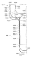
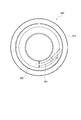
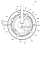
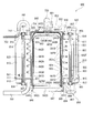
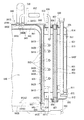
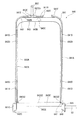
図2は、前記燃料電池システムにおける改質ユニットの概略構成を示す側面断面図である。図3は、前記改質ユニットの燃焼室部の概略構成を示す側面断面図である。図4は、前記改質ユニットの改質部の概略構成を示す側面断面図である。図5は、前記改質ユニットの改質器の一部を示す拡大した側面断面図である。図6は、前記改質ユニットのガス熱交換部の一部を示す拡大した側面断面図である。図7は、前記改質容器の第一改質器部材に取り付けられた保護管取付片部を示す平面図である。図8は、前記ガス熱交換部の第一円筒部材と第二円筒部材との組み付け状態を示す平面図である。図9は、前記改質ユニットのボイラを示す平面図である。図10は、前記改質ユニットのボイラを示す一部を切り欠いた側面図である。図11は、前記改質ユニットのCO除去部を示す平面図である。図12は、前記CO除去部を示す底面図である。図13は、前記改質ユニットのCO除去部を示す側面断面図である。図14は、前記CO除去部の一部を示す拡大した側面断面図である。図15は、CO変成器とCO選択酸化器との接続部を示す拡大した側面断面図である。図16は、前記CO除去部の排ガスクーラーを示す側面断面図である。図17は、前記CO除去部の排ガスクーラーを示す底面図である。
(Reforming unit)
Next, the configuration of the reforming unit 400 in the fuel cell system 100 described above will be described in detail.
FIG. 2 is a side sectional view showing a schematic configuration of the reforming unit in the fuel cell system. FIG. 3 is a side sectional view showing a schematic configuration of a combustion chamber portion of the reforming unit. FIG. 4 is a side sectional view showing a schematic configuration of a reforming unit of the reforming unit. FIG. 5 is an enlarged side sectional view showing a part of the reformer of the reforming unit. FIG. 6 is an enlarged side sectional view showing a part of the gas heat exchange section of the reforming unit. FIG. 7 is a plan view showing a protective tube attachment piece attached to the first reformer member of the reforming vessel. FIG. 8 is a plan view showing an assembled state of the first cylindrical member and the second cylindrical member of the gas heat exchange unit. FIG. 9 is a plan view showing a boiler of the reforming unit. FIG. 10 is a side view in which a part of the boiler of the reforming unit is cut away. FIG. 11 is a plan view showing a CO removing unit of the reforming unit. FIG. 12 is a bottom view showing the CO removing unit. FIG. 13 is a side cross-sectional view showing a CO removing unit of the reforming unit. FIG. 14 is an enlarged side sectional view showing a part of the CO removing unit. FIG. 15 is an enlarged side sectional view showing a connection portion between the CO transformer and the CO selective oxidizer. FIG. 16 is a side cross-sectional view showing an exhaust gas cooler of the CO removing unit. FIG. 17 is a bottom view showing an exhaust gas cooler of the CO removing unit.

改質ユニット400は、上述したように、水蒸気混合器140と、熱交換装置160と、改質器620と、CO変成器810と、CO選択酸化器830と、を備えた一体構成である。
また、熱交換装置160は、ボイラ650と、排ガスクーラー840と、を備えている。
そして、改質ユニット400は、図2に示すように、ユニット本体部400Aと、このユニット本体部400Aを覆う図示しない断熱部と、を備えている。また、ユニット本体部400Aは、改質装置としての改質部600と、配管部700と、CO除去部800と、にて構成されている。そして、ユニット本体部400Aは、燃料電池システム100を収容する図示しないケース体の底部に載置固定されるCO除去部800に対して、鉛直方向における上方に配管部700を介して改質部600が一体的に連結されて構成される。
As described above, the reforming unit 400 has an integrated configuration including the steam mixer 140, the heat exchange device 160, the reformer 620, the CO converter 810, and the CO selective oxidizer 830.
In addition, the heat exchange device 160 includes a boiler 650 and an exhaust gas cooler 840.
As shown in FIG. 2, the reforming unit 400 includes a unit main body portion 400A and a heat insulating portion (not shown) that covers the unit main body portion 400A. The unit main body 400A includes a reforming unit 600 as a reforming device, a piping unit 700, and a CO removing unit 800. The unit main body 400A is connected to the reforming unit 600 via the piping unit 700 upward in the vertical direction with respect to the CO removal unit 800 placed and fixed on the bottom of a case body (not shown) that houses the fuel cell system 100. Are integrally connected.

改質部600は、原料ガスを水蒸気改質するもので、改質外装ケース610を備えている。この改質外装ケース610は、上下面を開口する円筒状の円筒ケース611と、この円筒ケース611の上面を略覆って一体に取り付けられる上部ケース612と、円筒ケース611の下面を略覆って一体に取り付けられる支持台座部613と、を備えている。円筒ケース611は、略円筒形状の部材であり、例えば鋼板などにて略円筒状に形成、より具体的には管材である鋼板の板巻き管を用いて形成されている。上部ケース612は、円筒ケース611の上面側内周に嵌合挿入された略平板環状に形成され、内周縁側に後述するバーナーユニット151が取り付けられて、円筒ケース611の上面側を閉塞する。支持台座部613は、円筒ケース611の下端内周に嵌合挿入された略平板環状に形成され、改質部600と配管部700との間を連通する配管や後述する熱交換器としてのガス熱交換部640が突設されている以外には空隙がなく、改質部600と配管部700とを分離遮断している。   The reformer 600 is for reforming the raw material gas with steam, and includes a reformed outer case 610. The reformed exterior case 610 includes a cylindrical cylindrical case 611 having an open top and bottom surface, an upper case 612 that covers the upper surface of the cylindrical case 611 and is attached integrally, and a lower surface of the cylindrical case 611 that covers the lower surface. And a support pedestal portion 613 attached to the pedestal. The cylindrical case 611 is a substantially cylindrical member, and is formed, for example, in a substantially cylindrical shape using a steel plate or the like, and more specifically, is formed using a sheet-wound tube of a steel plate that is a tube material. The upper case 612 is formed in a substantially flat plate shape that is fitted and inserted into the inner periphery on the upper surface side of the cylindrical case 611, and a burner unit 151 described later is attached to the inner peripheral edge side to close the upper surface side of the cylindrical case 611. The support pedestal 613 is formed in a substantially flat plate shape that is fitted and inserted into the inner periphery of the lower end of the cylindrical case 611, and is a gas that serves as a pipe that communicates between the reforming unit 600 and the piping unit 700 or a heat exchanger described later. There is no air gap other than the heat exchange unit 640 protruding, and the reforming unit 600 and the piping unit 700 are separated and cut off.

そして、改質外装ケース610内には、改質器620、ガス熱交換部640と、ボイラ650と、が配設されている。
改質器620は、燃焼室部621と、バーナーユニット151と、改質容器622と、耐食性部材としての保護カバー623と、を備えている。
改質容器622は、図2、図4および図5に示すように、内周側にバーナーユニット151が取り付けられる燃焼室部621が配設される有底円筒状に構成されている。そして、改質容器622の軸方向の一端側である下端部にはガス熱交換部640が一体的に設けられ、改質容器622の内周側には改質容器622の内周面を覆う状態に保護カバー623が設けられている。さらに、ガス熱交換部640の外周側には、ボイラ650が配設されている。
In the reformed exterior case 610, a reformer 620, a gas heat exchange unit 640, and a boiler 650 are disposed.
The reformer 620 includes a combustion chamber portion 621, a burner unit 151, a reforming vessel 622, and a protective cover 623 as a corrosion resistant member.
As shown in FIGS. 2, 4, and 5, the reforming vessel 622 has a bottomed cylindrical shape in which a combustion chamber portion 621 to which the burner unit 151 is attached is disposed on the inner peripheral side. A gas heat exchange unit 640 is integrally provided at a lower end portion that is one end side in the axial direction of the reforming vessel 622, and an inner peripheral surface of the reforming vessel 622 is covered on an inner peripheral side of the reforming vessel 622. A protective cover 623 is provided in the state. Further, a boiler 650 is disposed on the outer peripheral side of the gas heat exchange unit 640.

燃焼室部621は、バーナーユニット151の燃焼により改質器620を加熱させるもので、図2および図3に示すように、例えば鋼板などにて、改質外装ケース610の上部ケース612の内周側に嵌合挿入される円筒状に形成された燃焼筒部621Aを有している。この燃焼筒部621Aの外周面には、細長鋼材にて中心軸に対して螺旋状に配設された螺旋流部621A1が一体的に設けられている。この螺旋流部621A1は、燃焼筒部621Aの内周面に当接することなく、かつ、後述する保護カバー623の内周面と燃焼筒部621Aの外周面との間を流通するバーナーユニット151の燃焼ガスが、中心軸に対して螺旋状に流通する状態に形成されている。
また、燃焼筒部621Aには、軸方向の一端となる上端側の所定の位置に、エンボス加工などにより内方に向けて膨出する状態に位置決めダボ621Bが設けられている。また、燃焼筒部621Aの軸方向の一端となる上端には、外方に向けて鍔状に一連に突出する支持フランジ621Cが設けられている。この支持フランジ621Cには、取付ボルト621Dが挿通されるボルト挿通孔621Eが開口形成されている。
また、燃焼室部621には、火炎整流部621Fが一体的に設けられている。この火炎整流部621Fは、外径が燃焼筒部621Aの内径と略同寸法で、燃焼筒部621Aの上端側に位置して溶接などにより一体的に取り付けられる取付円筒部621F1を有している。また、取付円筒部621F1の軸方向における一端となる下端には、先端側にしたがって次第に径小となる漏斗状の整流筒部621F2が一連に設けられている。そして、火炎整流部621Fは、燃焼筒部621Aの位置決めダボ621Bにて位置決めされ、取付円筒部621F1が溶接などにより燃焼筒部621Aの内周側の所定の位置に一体的に取り付けられている。
The combustion chamber section 621 heats the reformer 620 by the combustion of the burner unit 151. As shown in FIGS. 2 and 3, the combustion chamber section 621 is made of, for example, a steel plate and has an inner periphery of the upper case 612 of the reformed outer case 610. It has a combustion cylinder portion 621A formed in a cylindrical shape that is fitted and inserted on the side. A spiral flow portion 621A1 is integrally provided on the outer peripheral surface of the combustion cylinder portion 621A. The spiral flow portion 621A1 is not in contact with the inner peripheral surface of the combustion cylinder portion 621A, and the burner unit 151 that circulates between an inner peripheral surface of a protective cover 623 and an outer peripheral surface of the combustion cylinder portion 621A, which will be described later. Combustion gas is formed in a state of circulating spirally with respect to the central axis.
Further, the combustion cylinder portion 621A is provided with a positioning dowel 621B at a predetermined position on the upper end side which is one end in the axial direction so as to bulge inward by embossing or the like. Further, a support flange 621C is provided at the upper end, which is one end in the axial direction, of the combustion cylinder portion 621A. A bolt insertion hole 621E through which the mounting bolt 621D is inserted is formed in the support flange 621C.
Further, the combustion chamber portion 621 is integrally provided with a flame rectifying portion 621F. This flame rectifying part 621F has an attachment cylindrical part 621F1 whose outer diameter is substantially the same as the inner diameter of the combustion cylinder part 621A and is located on the upper end side of the combustion cylinder part 621A and attached integrally by welding or the like. . In addition, a funnel-shaped rectifying cylinder portion 621F2 having a diameter gradually decreasing in accordance with the tip end side is provided in series at the lower end which is one end in the axial direction of the mounting cylindrical portion 621F1. The flame rectifying unit 621F is positioned by a positioning dowel 621B of the combustion cylinder 621A, and the mounting cylinder 621F1 is integrally attached to a predetermined position on the inner peripheral side of the combustion cylinder 621A by welding or the like.

バーナーユニット151は、例えば、図2に示すように、鋳造形成されたバーナー本体部661と、原燃料や燃料電池スタック200の負極202から排出される未利用の水素を含むオフガスを燃焼させて火炎を生成する複数の図示しない燃焼口を有するバーナー部662と、を有している。
バーナー本体部661には、送気ブロワ170から供給される空気が一次空気として導入される第一空気導入部661Aと、供給される空気が二次空気として導入される図示しない第二空気導入部と、オフガスを導入して燃焼させるオフガス導入部661Bと、などが設けられている。また、第一空気導入部661Aには原燃料が供給される燃料供給管661Cが接続され、供給された原燃料は一次空気と混合されてバーナー本体部661に供給されて燃焼される。
そして、バーナーユニット151は、バーナー本体部661に鍔状に設けられた取付フランジ661Eが、燃焼室部621の支持フランジ621Cにさらに重なる状態に支持されて、取付ボルト621Dが螺着される。この状態で、改質外装ケース610の上端部が閉塞されて、一体的にバーナーユニット151が配設される。
なお、バーナーユニット151の取付状態は、バーナー部662の下端部が、燃焼室部621の火炎整流部621Fの整流筒部621F2内に略位置するとともに、改質容器622の上端部に略対応する位置となっている。
For example, as shown in FIG. 2, the burner unit 151 burns off-gas containing burner main body 661 formed by casting and unused hydrogen discharged from the raw fuel or the negative electrode 202 of the fuel cell stack 200 to form a flame. A burner section 662 having a plurality of combustion ports (not shown) for generating
The burner body 661 has a first air introduction part 661A in which air supplied from the air supply blower 170 is introduced as primary air, and a second air introduction part (not shown) in which supplied air is introduced as secondary air And an off-gas introduction part 661B for introducing and burning off-gas. In addition, a fuel supply pipe 661C to which raw fuel is supplied is connected to the first air introduction part 661A, and the supplied raw fuel is mixed with primary air, supplied to the burner body 661, and burned.
In the burner unit 151, a mounting flange 661E provided in a bowl shape on the burner body 661 is supported so as to further overlap the support flange 621C of the combustion chamber 621, and a mounting bolt 621D is screwed thereto. In this state, the upper end portion of the reformed exterior case 610 is closed, and the burner unit 151 is integrally provided.
The attached state of the burner unit 151 corresponds substantially to the upper end portion of the reforming vessel 622 while the lower end portion of the burner portion 662 is substantially located within the rectifying cylinder portion 621F2 of the flame rectifying portion 621F of the combustion chamber portion 621. Is in position.

保護カバー623は、バーナーユニット151の燃焼ガスによる改質容器622の部分的な過熱を防止しつつ、所定の温度分布で改質容器622を加熱させるもので、図2に示すように、有底円筒状に形成された改質容器622の内周側を覆うように、有底円筒状に形成されている。
この保護カバー623は、バーナーユニット151の燃焼ガスが当たるので、耐熱性および耐蝕性に優れたステンレス鋼板などにて形成される。そして、保護カバー623は、外径が改質容器622の内径より径小の円筒保護管部623Aを有している。この円筒保護管部623Aの下端縁には、この円筒保護管部623Aの下端面を閉塞する保護底部623Bが一連に設けられている。さらに、円筒保護管部623Aの軸方向の他端である上端縁には、外方に向けて折曲され、さらに下端側に向けて折曲されて改質容器622の上端部を覆う状態に取り付けられる保護端部623Cが設けられている。
そして、保護カバー623の保護底部623Bの下面と改質容器622との間には、断熱部材624が設けられている。
そして、バーナーユニット151で燃焼された燃焼ガスは、燃焼室部621と保護カバー623との間を上方に向けて流通して改質容器622の上部を回って改質容器622と円筒ケース611との間を下方に向けて流通する。
The protective cover 623 heats the reforming vessel 622 with a predetermined temperature distribution while preventing partial overheating of the reforming vessel 622 due to the combustion gas of the burner unit 151. As shown in FIG. It is formed in a bottomed cylindrical shape so as to cover the inner peripheral side of the reforming vessel 622 formed in a cylindrical shape.
The protective cover 623 is made of a stainless steel plate having excellent heat resistance and corrosion resistance because the combustion gas of the burner unit 151 is hit. The protective cover 623 has a cylindrical protective tube portion 623A whose outer diameter is smaller than the inner diameter of the reforming vessel 622. A protective bottom portion 623B that closes the lower end surface of the cylindrical protective tube portion 623A is provided in series at the lower end edge of the cylindrical protective tube portion 623A. Furthermore, the upper end edge, which is the other axial end of the cylindrical protective tube portion 623A, is bent outward and further bent toward the lower end side so as to cover the upper end portion of the reforming vessel 622. A protective end 623C to be attached is provided.
A heat insulating member 624 is provided between the lower surface of the protective bottom 623B of the protective cover 623 and the reforming vessel 622.
The combustion gas burned in the burner unit 151 flows upward between the combustion chamber portion 621 and the protective cover 623 and travels around the upper portion of the reforming vessel 622, and the reforming vessel 622 and the cylindrical case 611 It circulates in the downward direction.

改質容器622は、改質触媒が充填されて原料ガスを水蒸気改質するもので、図2、図4および図5に示すように、有底円筒状に構成されている。すなわち、改質容器622は、径寸法が異なり同軸上に位置する略筒状の第一改質器部材622A、第二改質器部材622Bおよび第三改質器部材622Cを備えた三重管構造を有し、内側から第一改質器部材622A、第二改質器部材622B、第三改質器部材622Cの順に配置されて構成されている。
第一改質器部材622Aは、図4および図5に示すように、略円筒状の第一改質筒部622A1と、この第一改質筒部622A1の軸方向の一端である下端に一連に設けられ第一改質筒部622A1の下端面を閉塞する改質底板部622A2とを有し、有底円筒状に形成されている。
第二改質器部材622Bは、内径が第一改質筒部622A1の外径より径大の略円筒状の第二改質筒部622B1と、この第二改質筒部622B1の軸方向の一端縁である下端縁に内方に向けてフランジ状に突出し、内周縁にガス熱交換部640が一体に連設される第二改質フランジ部622B2とを有し、略円筒状に形成されている。この第二改質フランジ部622B2には、エンボス加工などにより上方に向けて膨出する状態に位置決めダボ部622B3が設けられている。
第三改質器部材622Cは、内径が第二改質筒部622B1の外径より径大の略円筒状の第三改質筒部622C1と、この第三改質筒部622C1の軸方向の下端縁に内方に向けてフランジ状に突出し、内周縁にガス熱交換部640が一体に連設される第三改質フランジ部622C2とを有し、略円筒状に形成されている。
The reforming vessel 622 is filled with a reforming catalyst to steam reform the raw material gas, and has a bottomed cylindrical shape as shown in FIGS. That is, the reforming vessel 622 has a triple tube structure including a first cylindrical reformer member 622A, a second reformer member 622B, and a third reformer member 622C that have different diameters and are coaxially positioned. The first reformer member 622A, the second reformer member 622B, and the third reformer member 622C are arranged in this order from the inside.
As shown in FIG. 4 and FIG. 5, the first reformer member 622A is a series of a substantially cylindrical first reforming cylinder portion 622A1 and a lower end that is one end of the first reforming cylinder portion 622A1 in the axial direction. And a modified bottom plate portion 622A2 that closes the lower end surface of the first modified cylinder portion 622A1, and is formed in a bottomed cylindrical shape.
The second reformer member 622B includes a substantially cylindrical second reforming cylinder portion 622B1 having an inner diameter larger than the outer diameter of the first reforming cylinder portion 622A1, and the axial direction of the second reforming cylinder portion 622B1. It has a second reforming flange portion 622B2 that protrudes inwardly toward the lower end edge, which is one end edge, inwardly, and a gas heat exchanging portion 640 integrally connected to the inner peripheral edge, and is formed in a substantially cylindrical shape. ing. The second modified flange portion 622B2 is provided with a positioning dowel portion 622B3 so as to bulge upward by embossing or the like.
The third reformer member 622C has a substantially cylindrical third reforming cylinder portion 622C1 whose inner diameter is larger than the outer diameter of the second reforming cylinder portion 622B1, and the axial direction of the third reforming cylinder portion 622C1. It has a third modified flange portion 622C2 that protrudes inward from the lower end edge in a flange shape, and a gas heat exchanging portion 640 that is integrally connected to the inner peripheral edge, and is formed in a substantially cylindrical shape.

そして、改質容器622には、図2、図4および図5に示すように、第一改質器部材622Aの第一改質筒部622A1の上端外周縁と、第三改質器部材622Cの第三改質筒部622C1の上端内周縁との間に連設する折返し部としての改質リング端板622Dが設けられている。
この改質リング端板622Dには、外周縁および内周縁がそれぞれ同方向に屈曲されて接合屈曲部622D1が設けられ、改質リング端板622Dは第一改質筒部622A1および第三改質筒部622C1に面接合する状態に断面U字状に形成されている。この改質リング端板622Dにより、第一改質器部材622Aおよび第三改質器部材622Cの上端部が連結されて、保護カバー623の保護端部623Cにて覆われる改質容器622の上端部を閉塞する。
なお、改質リング端板622Dには、図示しない温度センサーを配設するためのセンサー保護管622Eが貫通されるセンサー配設孔622D2が設けられている。
As shown in FIGS. 2, 4 and 5, the reformer vessel 622 includes an upper outer peripheral edge of the first reformer cylinder portion 622A1 of the first reformer member 622A, and a third reformer member 622C. A reforming ring end plate 622D is provided as a turned-up portion that is connected to the inner periphery of the upper end of the third reforming cylinder portion 622C1.
The modified ring end plate 622D is provided with a joint bent portion 622D1 by bending the outer peripheral edge and the inner peripheral edge in the same direction, and the modified ring end plate 622D includes the first modified cylindrical portion 622A1 and the third modified portion. It is formed in a U-shaped cross section so as to be surface-bonded to the cylindrical portion 622C1. By this reforming ring end plate 622D, the upper ends of the first reformer member 622A and the third reformer member 622C are connected, and the upper end of the reforming vessel 622 covered with the protective end 623C of the protective cover 623. Block the part.
The reforming ring end plate 622D is provided with a sensor arrangement hole 622D2 through which a sensor protection tube 622E for arranging a temperature sensor (not shown) is passed.

また、改質容器622には、第一改質器部材622Aの第一改質筒部622A1の上端部の外周面に設けられ、第二改質器部材622Bの第二改質筒部622B1の上端部の内周面に向けて鍔状に突出し、第一改質器部材622Aと第二改質器部材622Bとの間を略閉塞する上部改質仕切部材622Fが設けられている。
この上部改質仕切部材622Fは、図4および図5に示すように、第一改質器部材622Aの第一改質筒部622A1の外周面に内周面が取り付けられる環状の取付管部622F1と、この取付管部622F1の下端縁が外方に向けて鍔状に折曲形成され、先端縁が第二改質筒部622B1の内周面に熱膨張によるクリアランスを考慮した間隙を介して対向する上部仕切鍔部622F2と、を有している。そして、上部仕切鍔部622F2には、改質ガスが流通可能に複数のガス流通孔622F3が開口形成されている。
さらに、上部改質仕切部材622Fの上部仕切鍔部622F2には、センサー保護管622Eが貫通されるセンサー貫通孔622F4が設けられている。
また、改質容器622には、図4および図7に示すように、第一改質器部材622Aの第一改質筒部622A1の外周面に位置して、センサー保護管622Eが貫通されるセンサー挿通孔622E1を有し、センサー保護管622Eを保持する保護管取付片部622E2が複数設けられている。
なお、センサー保護管622Eを設ける代わりに、例えば、温度センサーを第一改質器部材622Aあるいは第二改質器部材622Bに貼り付ける構成としてもよい。
Further, the reforming vessel 622 is provided on the outer peripheral surface of the upper end portion of the first reforming cylinder portion 622A1 of the first reformer member 622A, and the second reforming cylinder portion 622B1 of the second reformer member 622B. An upper reforming partition member 622F that protrudes in a bowl shape toward the inner peripheral surface of the upper end portion and substantially closes the space between the first reformer member 622A and the second reformer member 622B is provided.
As shown in FIGS. 4 and 5, the upper reforming partition member 622F has an annular mounting pipe portion 622F1 whose inner peripheral surface is attached to the outer peripheral surface of the first reforming cylinder portion 622A1 of the first reformer member 622A. And the lower end edge of the mounting pipe part 622F1 is bent outwardly in a bowl shape, and the front end edge is formed on the inner peripheral surface of the second modified cylinder part 622B1 via a gap in consideration of the clearance due to thermal expansion. And an upper partitioning rod portion 622F2 facing each other. The upper divider 622F2 is formed with a plurality of gas flow holes 622F3 so that the reformed gas can flow.
Further, a sensor through-hole 622F4 through which the sensor protection tube 622E is passed is provided in the upper partition rod portion 622F2 of the upper reforming partition member 622F.
Further, as shown in FIGS. 4 and 7, the sensor protection tube 622E is penetrated through the reforming vessel 622 at the outer peripheral surface of the first reforming cylinder portion 622A1 of the first reformer member 622A. A plurality of protective tube attachment pieces 622E2 each having a sensor insertion hole 622E1 and holding the sensor protective tube 622E are provided.
Instead of providing the sensor protection tube 622E, for example, a temperature sensor may be attached to the first reformer member 622A or the second reformer member 622B.

さらに、改質容器622には、図2、図4および図5に示すように、第二改質器部材622Bの第二改質フランジ部622B2に取り付けられ、上方である第一改質器部材622Aに向けて円筒状に突出する状態に、下部改質仕切部材622Gが設けられている。
この下部改質仕切部材622Gは、図4〜図6に示すように、内径が第一改質筒部622A1の外径より熱膨張などのクリアランスを考慮した寸法分径大の仕切筒部622G1と、この仕切筒部622G1の軸方向の一端側が内方に向けてフランジ状に突出し第二改質フランジ部622B2に溶接などにより取り付けられる仕切取付フランジ部622G2とを有した略円筒状に形成されている。
さらに、この下部改質仕切部材622Gには、仕切筒部622G1から仕切取付フランジ部622G2に連続する湾曲する部分に、原料ガスが流通可能な原料ガス流通孔622G3が複数開口形成されている。この原料ガス流通孔622G3は、仕切筒部622G1と第一改質筒部622A1とのクリアランスを流通する流通抵抗より小さい流通抵抗で、良好に原料ガスが流通するように形成されている。
なお、仕切取付フランジ部622G2には、第二改質フランジ部622B2の位置決めダボ部622B3が係合する仕切位置決め孔部622G4が設けられている。
Further, as shown in FIGS. 2, 4 and 5, the reformer vessel 622 is attached to the second reformer flange portion 622B2 of the second reformer member 622B and is located above the first reformer member. A lower reforming partition member 622G is provided so as to protrude in a cylindrical shape toward 622A.
As shown in FIGS. 4 to 6, the lower reforming partition member 622G includes a partition tube portion 622G1 whose inner diameter is larger than the outer diameter of the first reformed tube portion 622A1 in consideration of clearance such as thermal expansion. One end side in the axial direction of the partition tube portion 622G1 is formed in a substantially cylindrical shape having a partition mounting flange portion 622G2 that protrudes inwardly in a flange shape and is attached to the second modified flange portion 622B2 by welding or the like. Yes.
Further, the lower reforming partition member 622G is formed with a plurality of source gas flow holes 622G3 through which the source gas can flow in a curved portion that continues from the partition tube portion 622G1 to the partition mounting flange portion 622G2. This source gas flow hole 622G3 is formed so that the source gas flows well with a flow resistance smaller than the flow resistance flowing through the clearance between the partition tube portion 622G1 and the first reforming tube portion 622A1.
The partition mounting flange portion 622G2 is provided with a partition positioning hole portion 622G4 that engages with the positioning dowel portion 622B3 of the second reforming flange portion 622B2.

そして、改質容器622には、第一改質器部材622Aの改質底板部622A2と、下部改質仕切部材622Gと、ガス熱交換部640とにより、ガス熱交換部640からの原料ガスが流入する原料ガス流入室622H1が区画されている。また、改質容器622には、第一改質器部材622Aの第一改質筒部622A1と、第二改質器部材622Bの第二改質筒部622B1と、上部改質仕切部材622Fと、下部改質仕切部材622Gとにより、改質触媒が充填される改質室622H2が区画形成されている。さらに、改質容器622には、第二改質器部材622Bの第二改質筒部622B1と、第三改質器部材622Cの第三改質筒部622C1と、改質リング端板622Dと、第一改質筒部622A1の第一改質筒部622A1と、上部改質仕切部材622Fと、ガス熱交換部640とにより、改質ガスが流通する改質ガス流路622H3が区画形成されている。
原料ガス流入室622H1と改質室622H2とは、下部改質仕切部材622Gの原料ガス流通孔622G3により連通し、原料ガス流入室622H1に流入した原料ガスは、改質室622H2へ流通する。また、改質室622H2と改質ガス流路622H3とは、上部改質仕切部材622Fのガス流通孔622F3により連通し、改質室622H2で原料ガスが水蒸気改質されて生成する改質ガスが改質ガス流路622H3を流通し、再びガス熱交換部640に流入する。
なお、改質器620は、バーナーユニット151の燃焼ガスにより加熱される改質容器622の改質室622H2は、原料ガスが流入する下端が上端より多少温度が低い温度分布で加熱されコーキングを防止しつつ改質室622H2の軸方向の全域で効率よく改質処理できるように、燃焼室部621、バーナーユニット151および改質容器622が形成されている。また、改質容器622は、円筒形状に限らず、多角筒形状や楕円筒形状、星形筒形状などとしてもよい。
The reforming vessel 622 receives the raw material gas from the gas heat exchanging unit 640 by the reforming bottom plate portion 622A2 of the first reformer member 622A, the lower reforming partition member 622G, and the gas heat exchanging unit 640. An inflowing source gas inflow chamber 622H1 is defined. The reforming vessel 622 includes a first reforming cylinder portion 622A1 of the first reformer member 622A, a second reforming cylinder portion 622B1 of the second reformer member 622B, and an upper reforming partition member 622F. The reforming chamber 622H2 filled with the reforming catalyst is partitioned by the lower reforming partition member 622G. Further, the reforming vessel 622 includes a second reforming cylinder portion 622B1 of the second reformer member 622B, a third reforming cylinder portion 622C1 of the third reformer member 622C, and a reforming ring end plate 622D. The reformed gas flow path 622H3 through which the reformed gas flows is defined by the first reformed cylinder portion 622A1 of the first reformed cylinder portion 622A1, the upper reforming partition member 622F, and the gas heat exchange unit 640. ing.
The source gas inflow chamber 622H1 and the reforming chamber 622H2 communicate with each other through the source gas flow hole 622G3 of the lower reforming partition member 622G, and the source gas flowing into the source gas inflow chamber 622H1 flows into the reforming chamber 622H2. Further, the reforming chamber 622H2 and the reformed gas flow path 622H3 communicate with each other through the gas flow holes 622F3 of the upper reforming partition member 622F, and the reformed gas generated by steam reforming the raw material gas in the reforming chamber 622H2 is generated. It flows through the reformed gas flow path 622H3 and flows into the gas heat exchange unit 640 again.
The reformer 620 is heated by the combustion gas of the burner unit 151, and the reforming chamber 622H2 of the reforming vessel 622 is heated at a temperature distribution in which the lower end where the raw material gas flows is slightly lower than the upper end to prevent coking. However, the combustion chamber portion 621, the burner unit 151, and the reforming vessel 622 are formed so that the reforming process can be efficiently performed in the entire region of the reforming chamber 622H2. The reforming vessel 622 is not limited to a cylindrical shape, and may be a polygonal cylindrical shape, an elliptical cylindrical shape, a star cylindrical shape, or the like.

ガス熱交換部640は、原料ガスと改質ガスとの熱交換をするもので、図2、図4〜図6に示すように、改質容器622と同軸上で、かつ、改質容器622の鉛直下方に配設される。
このガス熱交換部640は、径寸法が異なり同軸上に位置する第一筒部材としての第一円筒部材642A、第二筒部材としての第二円筒部材642Bおよび第三筒部材としての第三円筒部材642Cを備えた三重管構造を有し、内側から第一円筒部材642A、第二円筒部材642B、第三円筒部材642Cの順に配置されて構成されている。
The gas heat exchanging unit 640 exchanges heat between the raw material gas and the reformed gas. As shown in FIGS. 2 and 4 to 6, the gas heat exchanging unit 640 is coaxial with the reforming vessel 622, and the reforming vessel 622. It is arrange | positioned vertically below.
This gas heat exchanging section 640 has a first cylindrical member 642A as a first cylindrical member having a different diameter and coaxially positioned, a second cylindrical member 642B as a second cylindrical member, and a third cylinder as a third cylindrical member. It has a triple-pipe structure provided with a member 642C, and is arranged from the inside in the order of a first cylindrical member 642A, a second cylindrical member 642B, and a third cylindrical member 642C.

第一円筒部材642Aは、軸方向の一端となる下端側が開放する断面逆U字状で、図4、図6および図8に示すように、円筒状の第一円筒部642A1と、この第一円筒部642A1の軸方向における他端側となる上端に一連に設けられ第一円筒部642A1の上端面を閉塞する円筒天板部642A2とを有し、有天円筒状に形成されている。
円筒天板部642A2の上面略中央には、上方に向けて折曲され、改質ユニット400の組立時に改質容器622の第一改質器部材622Aの改質底板部622A2に当接して支持する改質器ストッパ642A3が設けられている。この改質器ストッパ642A3により、改質容器622の原料ガス流入室622H1が区画形成される。
The first cylindrical member 642A has an inverted U-shaped cross section that opens at the lower end side that is one end in the axial direction. As shown in FIGS. 4, 6, and 8, the first cylindrical member 642A has a cylindrical first cylindrical portion 642A1 and the first cylindrical portion 642A. The cylindrical portion 642A1 has a cylindrical top plate portion 642A2 that is provided in series at the upper end on the other end side in the axial direction and closes the upper end surface of the first cylindrical portion 642A1, and is formed in a cylindrical shape.
At the center of the top surface of the cylindrical top plate portion 642A2, it is bent upward and is in contact with and supported by the reforming bottom plate portion 622A2 of the first reformer member 622A of the reforming vessel 622 when the reforming unit 400 is assembled. A reformer stopper 642A3 is provided. By this reformer stopper 642A3, the raw material gas inflow chamber 622H1 of the reforming vessel 622 is partitioned.

第二円筒部材642Bは、断面U字の有底円筒状で、第一円筒部642A1の外径より内径が大きい円筒状の第二円筒部642B1と、この第二円筒部642B1の軸方向の下端に一連に設けられ第二円筒部642B1の下端面を閉塞する円筒底板部642B2とを有している。
そして、円筒底板部642B2には、水蒸気混合器140に接続して水蒸気混合器140から水蒸気が混合された原料ガスが流通する原料ガス供給管642Dを貫通する原料ガス供給貫通孔642B5が設けられている。この原料ガス供給管642Dから供給される原料ガスは、第二円筒部材642Bと第一円筒部材642Aとにより囲まれた空間、すなわち原料ガス流入空間642E1に流入する。
また、第二円筒部642B1には、下端側に位置してエンボス加工などにより内方に向けて膨出する突出部としての支持ダボ部642B3が、周方向で6等分する6箇所に設けられている。これら支持ダボ部642B3は、第一円筒部材642Aの下端縁が当接して第一円筒部材642Aを支持可能に膨出形成されている。さらに、第二円筒部642B1には、支持ダボ部642B3の位置より上端側に位置して、エンボス加工などにより所定の高さ寸法で内方に向けて膨出する凸部としての間隙ダボ部642B4が周方向で6等分する位置に設けられている。これら間隙ダボ部642B4は、支持ダボ部642B3に支持された第一円筒部642A1の外周面に当接し、第一円筒部642A1の外周面と第二円筒部642B1の内周面との間に所定の幅、例えば0.1mm以上10mm以下、本実施形態では0.5mmの間隙を形成させる。この隙間は、原料ガス流入空間642E1に連通し原料ガスが流通する原料ガス流路642E2となる。
ここで、この原料ガス流路642E2の隙間が0.1mmより狭くなると、第一円筒部642A1と第二円筒部642B1の熱膨張差により流路が閉塞するという不都合が生じるおそれがある。また、10mmより広くなると、第一円筒部642A1と第二円筒部642B1との間の隙間部分での差圧が小さくなり、周方向で偏流が生じるという不都合が生じるおそれがある。これらのことから、原料ガス流路642E2の隙間は、0.1mm以上10mm以下に設定することが好ましい。さらに、0.5mm以上2.0mm以下に設定することがより好ましい。
なお、支持ダボ部642B3および間隙ダボ部642B4は、周方向で6等分する位置に設ける構成に限らず、第一円筒部材642Aを確実に支持でき、周方向で均等な間隙を形成するいずれの数や形状で形成することができる。
そして、第二円筒部642B1の上端部は、改質容器622の第二改質フランジ部622B2の内周縁に連結され、原料ガス流路642E2は、改質容器622の原料ガス流入室622H1に連通する。
The second cylindrical member 642B is a bottomed cylindrical shape having a U-shaped cross section, and has a cylindrical second cylindrical portion 642B1 having an inner diameter larger than the outer diameter of the first cylindrical portion 642A1, and a lower end in the axial direction of the second cylindrical portion 642B1. And a cylindrical bottom plate portion 642B2 that is provided in series and closes the lower end surface of the second cylindrical portion 642B1.
The cylindrical bottom plate portion 642B2 is provided with a source gas supply through hole 642B5 that is connected to the steam mixer 140 and penetrates the source gas supply pipe 642D through which the source gas mixed with the steam flows from the steam mixer 140. Yes. The source gas supplied from the source gas supply pipe 642D flows into a space surrounded by the second cylindrical member 642B and the first cylindrical member 642A, that is, a source gas inflow space 642E1.
The second cylindrical portion 642B1 is provided with six support dowel portions 642B3, which are located on the lower end side and bulge inward by embossing or the like, which are divided into six equal parts in the circumferential direction. ing. These support dowels 642B3 are formed to bulge so that the lower end edge of the first cylindrical member 642A abuts and can support the first cylindrical member 642A. Further, the second cylindrical portion 642B1 is located on the upper end side from the position of the support dowel portion 642B3, and the gap dowel portion 642B4 as a convex portion that bulges inward at a predetermined height by embossing or the like. Is provided at a position that divides into six equal parts in the circumferential direction. These gap dowel portions 642B4 are in contact with the outer peripheral surface of the first cylindrical portion 642A1 supported by the support dowel portion 642B3, and are predetermined between the outer peripheral surface of the first cylindrical portion 642A1 and the inner peripheral surface of the second cylindrical portion 642B1. , For example, a gap of 0.5 mm is formed in this embodiment. This gap serves as a raw material gas flow path 642E2 through which the raw material gas flows and communicates with the raw material gas inflow space 642E1.
Here, if the gap between the source gas flow paths 642E2 is narrower than 0.1 mm, there is a possibility that the flow path is closed due to a difference in thermal expansion between the first cylindrical portion 642A1 and the second cylindrical portion 642B1. On the other hand, when the width is larger than 10 mm, the differential pressure in the gap portion between the first cylindrical portion 642A1 and the second cylindrical portion 642B1 becomes small, and there is a possibility that inconvenience that drift occurs in the circumferential direction may occur. For these reasons, it is preferable that the gap of the source gas flow path 642E2 is set to 0.1 mm or more and 10 mm or less. Furthermore, it is more preferable to set to 0.5 mm or more and 2.0 mm or less.
The support dowel portion 642B3 and the gap dowel portion 642B4 are not limited to the configuration provided at a position equally divided into six in the circumferential direction, and any one that can reliably support the first cylindrical member 642A and forms a uniform gap in the circumferential direction. It can be formed in numbers or shapes.
The upper end portion of the second cylindrical portion 642B1 is connected to the inner peripheral edge of the second reforming flange portion 622B2 of the reforming vessel 622, and the source gas flow path 642E2 communicates with the source gas inflow chamber 622H1 of the reforming vessel 622. To do.

第三円筒部材642Cは、断面U字の有底円筒状で、第二円筒部642B1の外径より内径が大きい円筒状の第三円筒部642C1と、この第三円筒部642C1の軸方向の下端に一連に設けられ第三円筒部642C1の下端面を閉塞する熱交換底板部642C2とを有している。
そして、第三円筒部642C1には、エンボス加工などにより内方に向けて所定の高さ寸法で膨出する凸部としての隙間ダボ部642C3が周方向で6等分する位置に設けられている。これら隙間ダボ部642C3は、第二円筒部642B1の外周面に当接し、第二円筒部642B1の外周面と第三円筒部642C1の内周面との間に所定の幅、例えば0.1mm以上10mm以下、本実施形態では0.5mmの間隙を形成させる。
この第三円筒部642C1の上端部は、改質容器622の第三改質フランジ部622C2の内周縁に連結されている。そして、第二円筒部642B1の外周面と第三円筒部642C1の内周面との間は、改質容器622の改質ガス流路622H3に連通する改質ガス流通路642E3となる。この改質ガス流通路642E3の隙間は、0.1mmより狭くなると、第二円筒部642B1と第三円筒部642C1の熱膨張差により流路が閉塞するという不都合が生じるおそれがある。また、10mmより広くなると、第二円筒部642B1と第三円筒部642C1との隙間部分での差圧が小さくなり、周方向で偏流が生じるという不都合が生じるおそれがある。これらのことから、改質ガス流通路642E3の隙間は0.1mm以上10mm以下に設定することが好ましい。さらに、0.5mm以上2.0mm以下に設定することがより好ましい。
なお、隙間ダボ部642C3は、第二円筒部材642Bの支持ダボ部642B3および間隙ダボ部642B4と一致しない位置に設け、確実に第二円筒部材642Bに当接して所定の間隙の改質ガス流通路642E3を形成するように設ける。そして、隙間ダボ部642C3は、周方向で6等分する構成に限らず、第一円筒部材642Aを確実に支持でき、周方向で均等な間隙を形成する数や形状で形成すればよい。
また、熱交換底板部642C2には、改質ガス流出管642Fが貫通する改質ガス流出貫通孔642C4が設けられている。この改質ガス流出管642Fは、改質ガス流通路642E3と連通し、改質容器622からガス熱交換部640に流入し、原料ガス流路642E2を流通する原料ガスと熱交換させつつ改質ガス流通路642E3を流通する改質ガスを、ガス熱交換部640から流出させる。
また、第一円筒部材642A、第二円筒部材642B、第三円筒部材642Cは略コップ状に形成されているので、プレス成形で容易に製作でき、組み立ても容易で製造コストを低減できる。さらに、支持ダボ部642B3、間隙ダボ部642B4、隙間ダボ部642Cも内周側に突出する形状としているため、ダボ加工も容易にできる。
The third cylindrical member 642C has a bottomed cylindrical shape with a U-shaped cross section, and has a cylindrical third cylindrical portion 642C1 having an inner diameter larger than the outer diameter of the second cylindrical portion 642B1, and a lower end in the axial direction of the third cylindrical portion 642C1. And a heat exchange bottom plate portion 642C2 that is provided in series and closes the lower end surface of the third cylindrical portion 642C1.
The third cylindrical portion 642C1 is provided with a gap dowel portion 642C3 as a convex portion that bulges inward at a predetermined height by embossing or the like at a position that divides into six equal parts in the circumferential direction. . These gap dowel portions 642C3 are in contact with the outer peripheral surface of the second cylindrical portion 642B1, and have a predetermined width, for example, 0.1 mm or more, between the outer peripheral surface of the second cylindrical portion 642B1 and the inner peripheral surface of the third cylindrical portion 642C1. A gap of 10 mm or less and 0.5 mm in this embodiment is formed.
The upper end portion of the third cylindrical portion 642C1 is connected to the inner peripheral edge of the third reforming flange portion 622C2 of the reforming vessel 622. A reformed gas flow passage 642E3 communicating with the reformed gas channel 622H3 of the reforming vessel 622 is formed between the outer peripheral surface of the second cylindrical portion 642B1 and the inner peripheral surface of the third cylindrical portion 642C1. If the gap between the reformed gas flow passages 642E3 is narrower than 0.1 mm, there is a possibility that the flow path is blocked due to a difference in thermal expansion between the second cylindrical portion 642B1 and the third cylindrical portion 642C1. On the other hand, if the width is larger than 10 mm, the differential pressure in the gap portion between the second cylindrical portion 642B1 and the third cylindrical portion 642C1 becomes small, and there is a possibility that inconvenience arises in that drift occurs in the circumferential direction. For these reasons, the clearance of the reformed gas flow passage 642E3 is preferably set to 0.1 mm or more and 10 mm or less. Furthermore, it is more preferable to set to 0.5 mm or more and 2.0 mm or less.
The gap dowel portion 642C3 is provided at a position that does not coincide with the support dowel portion 642B3 and the gap dowel portion 642B4 of the second cylindrical member 642B, and reliably contacts the second cylindrical member 642B so as to have a reformed gas flow passage with a predetermined gap. Provided to form 642E3. The gap dowel portion 642C3 is not limited to being divided into six equal parts in the circumferential direction, and may be formed with a number or shape that can reliably support the first cylindrical member 642A and form a uniform gap in the circumferential direction.
The heat exchange bottom plate portion 642C2 is provided with a reformed gas outflow through hole 642C4 through which the reformed gas outflow pipe 642F passes. This reformed gas outflow pipe 642F communicates with the reformed gas flow passage 642E3, flows into the gas heat exchange section 640 from the reforming vessel 622, and reforms while exchanging heat with the source gas flowing through the source gas channel 642E2. The reformed gas flowing through the gas flow passage 642E3 is caused to flow out of the gas heat exchange unit 640.
In addition, since the first cylindrical member 642A, the second cylindrical member 642B, and the third cylindrical member 642C are formed in a substantially cup shape, they can be easily manufactured by press molding, can be easily assembled, and the manufacturing cost can be reduced. Further, since the support dowel portion 642B3, the gap dowel portion 642B4, and the gap dowel portion 642C also have a shape protruding to the inner peripheral side, dowel processing can be easily performed.

改質部600のボイラ650は、詳細は後述するが、排ガスクーラー840からCO除去熱交換部850を介して加熱された水(純水181)を、バーナーユニット151の燃焼ガスとの熱交換により加熱して水蒸気を生成させる。このボイラ650は、図2、図9および図10に示すように、二重管構造に構成されている。このボイラ650は、純水181が流通される改質水内管651と、この改質水内管651を嵌挿する排気風路外管652と、を備えている。
排気風路外管652は、軸方向の一端が開放され、軸方向の他端が支持台座部613の熱交換孔613Aに溶接などにより嵌合固定され、円筒ケース611の内径より径小の所定の曲率半径で螺旋状に形成されている。すなわち、排気風路外管652は、支持台座部613の上面側および下面側を連通する状態に配設され、バーナーユニット151にて燃焼された燃焼ガスが、改質容器622の内周側から上端側を介して外周側を下方に向けて流通し、支持台座部613の上面側から排気風路外管652内を介して支持台座部613の下面側に流通する状態となっている。
改質水内管651は、軸方向の一端側が排気風路外管652の開放する一端から延出するとともに、軸方向の他端側が支持台座部613に接続する排気風路外管652の他端から延出する状態に、排気風路外管652内に同軸上に配設されている。なお、詳細は後述するが、純水181と燃焼ガスとの熱交換効率の点で、改質水内管651は略同軸上に排気風路外管652内に嵌挿されて配設することが好ましいが、同軸上に位置させるための配管やスペーサなどの別部材を設けるなどの点で、単に嵌挿して配設する構成でよい。そして、改質水内管651は、詳細は後述するが、熱交換により発生する水蒸気の流出側に相当する端部となる軸方向の一端側が、支持台座部613を貫通して支持台座部613の下面側に延出し、水蒸気混合器140に接続する状態に配設されている。なお、改質水内管651の支持台座部613の貫通部分は、略気密に溶接やロウ付けなどによりシールされる。また、改質水内管651における支持台座部613の下面側に延出する軸方向の他端側には、詳細は後述するが、改質水としての純水181が供給される排ガスクーラー840に接続するCO除去熱交換部850が接続され、改質水内管651内に排ガスクーラー840およびCO除去熱交換部850で熱交換により加熱された純水181が流通される。そして、ボイラ650は、改質水内管651に流通する純水181を排気風路外管652に流通する燃焼ガスと熱交換させて、水蒸気を生成する。
Although the boiler 650 of the reforming unit 600 will be described in detail later, water (pure water 181) heated from the exhaust gas cooler 840 via the CO removal heat exchange unit 850 is exchanged with the combustion gas of the burner unit 151. Heat to produce water vapor. The boiler 650 is configured in a double tube structure as shown in FIGS. The boiler 650 includes a reformed water inner pipe 651 through which pure water 181 is circulated, and an exhaust air duct outer pipe 652 into which the reformed water inner pipe 651 is inserted.
One end of the exhaust air passage outer pipe 652 is opened in the axial direction, and the other end in the axial direction is fitted and fixed to the heat exchange hole 613A of the support base 613 by welding or the like, and has a predetermined diameter smaller than the inner diameter of the cylindrical case 611. It is formed in a spiral shape with a curvature radius of. That is, the exhaust air passage outer pipe 652 is disposed in a state where the upper surface side and the lower surface side of the support pedestal 613 communicate with each other, and the combustion gas burned in the burner unit 151 flows from the inner peripheral side of the reforming vessel 622. The outer peripheral side is circulated downward through the upper end side, and is circulated from the upper surface side of the support pedestal portion 613 to the lower surface side of the support pedestal portion 613 through the inside of the exhaust air duct outer tube 652.
The reformed water inner pipe 651 has one end side in the axial direction extending from one end where the exhaust air path outer pipe 652 is opened, and the other end side in the axial direction is connected to the support pedestal 613 in addition to the exhaust air path outer pipe 652. In the state extending from the end, it is arranged coaxially in the exhaust air duct outer tube 652. Although details will be described later, in terms of heat exchange efficiency between pure water 181 and the combustion gas, the reformed water inner pipe 651 is disposed substantially coaxially in the exhaust air duct outer pipe 652. However, a configuration in which a separate member such as a pipe or a spacer for positioning on the same axis is provided may be used. As will be described in detail later, the reformed water inner pipe 651 has one end side in the axial direction serving as an end corresponding to the outflow side of water vapor generated by heat exchange passing through the support pedestal 613 and the support pedestal 613. It is arranged in a state of extending to the lower surface side of the water and connecting to the steam mixer 140. The penetration portion of the support pedestal 613 of the modified water inner pipe 651 is sealed in a substantially airtight manner by welding or brazing. An exhaust gas cooler 840 to which pure water 181 as reforming water is supplied is described later in detail on the other end side in the axial direction of the reforming water inner pipe 651 extending to the lower surface side of the support pedestal 613. The CO removal heat exchanging unit 850 connected to is connected, and the exhaust gas cooler 840 and the pure water 181 heated by heat exchange in the CO removal heat exchanging unit 850 are circulated in the reformed water inner pipe 651. The boiler 650 heat-exchanges the pure water 181 flowing through the reformed water inner pipe 651 with the combustion gas flowing through the exhaust air duct outer pipe 652 to generate water vapor.

改質ユニット400の配管部700は、図2に示すように、配管外装ケース710を備えている。この配管外装ケース710は、円筒状に形成されている。この配管外装ケース710は、軸方向の一端となる下端側にCO除去部800が嵌合挿入され、溶接やロウ付けなどにより一体的に連結される。また、配管外装ケース710は、軸方向の他端となる上端側に改質部600の支持台座部613の外周縁が嵌合挿入され、溶接やロウ付けなどにより一体的に連結される。
この配管外装ケース710には、脱硫器310における脱硫容器の流出口から流出する脱硫処理後の原燃料が流通する原燃料管720が貫通されている。この原燃料管720は、水蒸気混合器140に接続され、ボイラ650からの水蒸気が混合される。
また、配管外装ケース710には、CO除去部800から延出する排ガス管730が貫通され、改質ユニット400外へバーナーユニット151の燃焼ガスを排出させる。すなわち、配管外装ケース710の内周側は、ボイラ650におけるバーナーユニット151の燃焼ガスが流通する排気風路外管652の内周側に連通し、燃焼ガスが流入する。この燃焼ガスは、詳細は後述するが、配管外装ケース710に連結するCO除去部800に流通してさらに熱交換により冷却され、CO除去部800から排ガス管730を介して改質ユニット400外へ排ガスとして排気される。
The piping unit 700 of the reforming unit 400 includes a piping outer case 710 as shown in FIG. The pipe outer case 710 is formed in a cylindrical shape. In this pipe outer case 710, a CO removing portion 800 is fitted and inserted into the lower end side which is one end in the axial direction, and is integrally connected by welding or brazing. Further, the outer periphery of the support pedestal 613 of the reforming unit 600 is fitted and inserted into the pipe outer case 710 on the upper end side which is the other end in the axial direction, and is integrally connected by welding or brazing.
A raw fuel pipe 720 through which the raw fuel after desulfurization flowing out from the outlet of the desulfurization vessel in the desulfurizer 310 flows is passed through the pipe outer case 710. The raw fuel pipe 720 is connected to the steam mixer 140, and the steam from the boiler 650 is mixed.
Further, an exhaust gas pipe 730 extending from the CO removing unit 800 is penetrated through the pipe outer case 710, and the combustion gas of the burner unit 151 is discharged out of the reforming unit 400. That is, the inner peripheral side of the pipe outer case 710 communicates with the inner peripheral side of the exhaust air duct outer pipe 652 through which the combustion gas of the burner unit 151 in the boiler 650 flows, and the combustion gas flows in. As will be described in detail later, this combustion gas flows through the CO removing unit 800 connected to the pipe outer case 710, and is further cooled by heat exchange, and is discharged from the CO removing unit 800 to the outside of the reforming unit 400 through the exhaust gas pipe 730. Exhaust as exhaust gas.

CO除去部800は、図2に示すように、CO変成器810と、熱処理手段820と、CO選択酸化器830と、排ガスクーラー840と、CO除去熱交換部850と、台座ケース860と、を備えている。
そして、改質外装ケース610と、配管外装ケース710と、CO変成器810の一部と、台座ケース860とにより、ユニット本体部400Aの外装ケースが構成される。
台座ケース860は、径寸法が配管外装ケース710と略同寸法の有底円筒状に形成され、開放する上端縁には、詳細は後述するが、CO変成器810が嵌合挿入され、溶接やロウ付けなどにより一体的に連結される。
As shown in FIG. 2, the CO removal unit 800 includes a CO converter 810, a heat treatment means 820, a CO selective oxidizer 830, an exhaust gas cooler 840, a CO removal heat exchange unit 850, and a base case 860. I have.
The reforming outer case 610, the piping outer case 710, a part of the CO transformer 810, and the base case 860 constitute an outer case of the unit main body 400A.
The pedestal case 860 is formed in a bottomed cylindrical shape having a diameter substantially the same as that of the pipe exterior case 710, and a CO transformer 810 is fitted and inserted into the open upper end edge, as will be described in detail later. They are connected together by brazing or the like.

そして、CO除去部800は、図2、図13〜図15に示すように、径寸法が異なり同軸上に位置する略筒状の第一CO除去部材801、第二CO除去部材802、第三CO除去部材803、および第四CO除去部材804を備えた四重管構造を有し、外側から第一CO除去部材801、第二CO除去部材802、第三CO除去部材803、および第四CO除去部材804の順に配置されて構成されている。
そして、第一CO除去部材801の軸方向の両端縁と、第二CO除去部材802の軸方向の両端縁との間には、図2、図11〜図15に示すように、略平板環状の外周側端板805が連設され、第一CO除去部材801と第二CO除去部材802と外周側端板805とにより、円筒形状のCO変成器810が構成される。
また、第三CO除去部材803の軸方向の両端縁と、第四CO除去部材804の軸方向の両端縁との間には、略平板環状の内周側端板806が連設され、第三CO除去部材803と第四CO除去部材804と内周側端板806とにより、円筒形状のCO変成器810の内側に同軸上に位置する円筒形状のCO選択酸化器830が構成される。
さらに、第二CO除去部材802の軸方向の両端縁と、第三CO除去部材803の軸方向の両端縁との間には、架橋する状態に複数の連結支持部材807が連結され、CO変成器810とCO選択酸化器830とが一体的に連結される。連結支持部材807には、第二CO除去部材802および第三CO除去部材803間の間隙を維持するスペーサ部807Aが一体に設けられている。そして、第二CO除去部材802および第三CO除去部材803間は、上端側が配管部700の配管外装ケース710内に連通し、下端側が台座ケース860内に連通する熱処理手段820が構成される。
なお、CO除去部800についても、円筒形に限らず、多角筒状や楕円筒状、星形筒状などとしてもよい。
As shown in FIGS. 2 and 13 to 15, the CO removing unit 800 includes a substantially cylindrical first CO removing member 801, a second CO removing member 802, It has a quadruple tube structure including a CO removing member 803 and a fourth CO removing member 804, and from the outside, a first CO removing member 801, a second CO removing member 802, a third CO removing member 803, and a fourth CO The removing members 804 are arranged in this order.
As shown in FIGS. 2 and 11 to 15, a substantially flat plate-like ring is formed between both axial edges of the first CO removing member 801 and both axial edges of the second CO removing member 802. The first CO removing member 801, the second CO removing member 802, and the outer circumferential end plate 805 constitute a cylindrical CO transformer 810.
Further, between the both end edges in the axial direction of the third CO removal member 803 and the both end edges in the axial direction of the fourth CO removal member 804, a substantially flat plate-shaped inner peripheral side end plate 806 is connected, The third CO removing member 803, the fourth CO removing member 804, and the inner peripheral side end plate 806 constitute a cylindrical CO selective oxidizer 830 coaxially positioned inside the cylindrical CO transformer 810.
Further, a plurality of connection support members 807 are connected in a bridging state between both end edges in the axial direction of the second CO removal member 802 and both end edges in the axial direction of the third CO removal member 803. The unit 810 and the CO selective oxidizer 830 are integrally connected. The connection support member 807 is integrally provided with a spacer portion 807A that maintains a gap between the second CO removal member 802 and the third CO removal member 803. Further, between the second CO removal member 802 and the third CO removal member 803, a heat treatment means 820 is constructed in which the upper end side communicates with the pipe outer case 710 of the pipe section 700 and the lower end side communicates with the base case 860.
The CO removing unit 800 is not limited to a cylindrical shape, and may be a polygonal cylindrical shape, an elliptical cylindrical shape, a star cylindrical shape, or the like.

CO変成器810内には、図2、図13〜図15に示すように、軸方向の上部側と下部側とのそれぞれにCO変成区画板811が設けられている。これらCO変成区画板811は、第二CO除去部材802の外周面から、第一CO除去部材801の内周面に向けて鍔状に設けられ、改質ガスが流通可能に複数の孔が設けられている。これらCO変成区画板811により、CO変成器810内には、軸方向の下部から、ガス拡散領域812と、CO変成触媒が充填されたCO変成反応領域813と、ガス収束領域814とが、互いに改質ガスを流通可能に区画形成されている。
なお、CO変成区画板811と第一CO除去部材801の内周面との間には、熱膨張などのクリアランスが設けられている。
そして、CO変成器810には、ガス熱交換部640に連結された改質ガス流出管642Fが連結されている。この改質ガス流出管642Fは、CO変成器810の上端側の外周側端板805およびCO変成区画板811を貫通してガス拡散領域812に連通する状態に連結されている。
また、CO変成器810には、上端側の外周側端板805で改質ガス流出管642Fが貫通する位置とは略径方向の反対側に位置して、連絡管740の一端が連結されている。この連絡管740は、U字状に屈曲形成され、他端側がCO選択酸化器830の上端側の内周側端板806に連結されている。さらに、CO変成器810には、連結する連絡管740の一端内に同軸上に嵌合挿入する酸素混合気体供給手段としての空気導入管750が、上端側の外周側端板805の外周側から貫通する状態に設けられている。この空気導入管750は、図示しないブロワなどが設けられ、酸素を含有する気体、例えば空気を連絡管740内に供給する。
そして、ガス熱交換部640から流出し改質ガス流出管642Fを流通する改質ガスは、CO変成器810のガス拡散領域812に流入され、CO変成反応領域813を流通して改質ガス中のCOが変成され、ガス収束領域814から連絡管740を介して、空気導入管750から供給される空気が混合されてCO選択酸化器830へ流通する。
また、CO変成器810には、CO変成反応領域813の下端側に位置して、CO除去熱交換部850を構成するCO変成冷却管851が配設されている。CO変成するシフト反応は、発熱反応であり、CO変成触媒により直ちに反応が進行することから、発熱反応により温度が高くなる傾向となるCO変成反応領域813の下端側である改質ガスが流通する上流側の領域に、CO変成冷却管851が配設される。このCO変成冷却管851は、詳細は後述するが、熱処理手段820を通ってボイラ650の改質水内管651に連結され、改質ガスとの熱交換により加熱された流通する水(純水181)をボイラ650に供給する。
さらに、CO変成器810には、ガス拡散領域812内の温度を測定する図示しない温度センサーを収容する温度センサー保護管815が配設されている。
In the CO converter 810, as shown in FIGS. 2 and 13 to 15, CO conversion partition plates 811 are provided on the upper and lower sides in the axial direction. These CO metamorphic partition plates 811 are provided in a bowl shape from the outer peripheral surface of the second CO removing member 802 toward the inner peripheral surface of the first CO removing member 801, and are provided with a plurality of holes through which the reformed gas can flow. It has been. By these CO shift dividing plates 811, the gas diffusion region 812, the CO shift reaction region 813 filled with the CO shift catalyst, and the gas converging region 814 are inserted into the CO shift converter 810 from the lower part in the axial direction. A compartment is formed so that the reformed gas can flow.
Note that a clearance such as thermal expansion is provided between the CO-transforming partition plate 811 and the inner peripheral surface of the first CO removing member 801.
The CO converter 810 is connected to a reformed gas outflow pipe 642F connected to the gas heat exchange unit 640. The reformed gas outflow pipe 642F is connected to the gas diffusion region 812 through the outer peripheral end plate 805 and the CO conversion partition plate 811 on the upper end side of the CO converter 810.
In addition, one end of a connecting pipe 740 is connected to the CO transformer 810, which is positioned on the opposite side to the position where the reformed gas outflow pipe 642F passes through the outer peripheral end plate 805 on the upper end side. Yes. The connecting pipe 740 is bent in a U shape, and the other end is connected to an inner peripheral end plate 806 on the upper end side of the CO selective oxidizer 830. Further, the CO transformer 810 has an air introduction pipe 750 as an oxygen mixed gas supply means that is coaxially fitted and inserted into one end of the connecting pipe 740 to be connected from the outer peripheral side of the outer peripheral end plate 805 on the upper end side. It is provided in a penetrating state. The air introduction pipe 750 is provided with a blower (not shown) and the like, and supplies a gas containing oxygen, for example, air, into the communication pipe 740.
Then, the reformed gas flowing out from the gas heat exchange unit 640 and flowing through the reformed gas outlet pipe 642F flows into the gas diffusion region 812 of the CO converter 810, and flows through the CO shift reaction region 813 to enter the reformed gas. The CO is transformed, and the air supplied from the air introduction pipe 750 is mixed from the gas converging region 814 through the communication pipe 740 and flows to the CO selective oxidizer 830.
The CO converter 810 is provided with a CO conversion cooling pipe 851 that constitutes the CO removal heat exchange unit 850, located on the lower end side of the CO conversion reaction region 813. The shift reaction that undergoes CO conversion is an exothermic reaction, and since the reaction proceeds immediately by the CO conversion catalyst, the reformed gas on the lower end side of the CO conversion reaction region 813 that tends to increase in temperature due to the exothermic reaction flows. A CO shift cooling pipe 851 is disposed in the upstream region. As will be described in detail later, this CO shift cooling pipe 851 is connected to the reformed water inner pipe 651 of the boiler 650 through the heat treatment means 820, and circulated water (pure water) heated by heat exchange with the reformed gas. 181) is supplied to boiler 650.
Further, the CO transformer 810 is provided with a temperature sensor protective tube 815 that houses a temperature sensor (not shown) that measures the temperature in the gas diffusion region 812.

CO選択酸化器830は、CO変成器810と同様に、内部の軸方向の上部側と下部側とのそれぞれにCO選択酸化区画板831が設けられている。これらCO選択酸化区画板831は、第四CO除去部材804の外周面から、第三CO除去部材803の内周面に向けて鍔状に設けられ、改質ガスが流通可能に複数の孔が設けられている。これらCO選択酸化区画板831により、CO選択酸化器830内には、軸方向の上部から、連絡管740が連通する拡散領域832と、CO選択酸化触媒が充填されたCO選択酸化反応領域833と、収束領域834とが、互いに改質ガスを流通可能に区画形成されている。
なお、CO選択酸化区画板831と第三CO除去部材803の内周面との間には、熱膨張などのクリアランスが設けられている。
また、CO選択酸化器830には、下端側の端板806に、内部の収束領域834に連通する燃料ガス管760が連結されている。
そして、CO変成器810から空気導入管750より空気が混合されて連絡管740を流通する改質ガスは、CO選択酸化器830の拡散領域832内に流入し、CO選択酸化反応領域833を流通して改質ガス中のCOが二酸化炭素(CO2)に酸化され、改質ガス中のCOが除去され、燃料ガスとして燃料ガス管760から改質ユニット400外へ流出される。
また、CO選択酸化器830には、CO除去熱交換部850を構成するCO選択酸化冷却管852が配設されている。このCO選択酸化冷却管852は、CO選択酸化反応領域833に螺旋状に配設され、CO選択酸化反応領域833を冷却する。このCO選択酸化冷却管852は、螺旋ピッチが、改質ガスが流入する上部側が狭いピッチで、下部側が広いピッチとなるように配設されている。さらに、CO選択酸化冷却管852は、CO選択酸化反応領域833の径方向で略中央より外周側に変位して配設する。すなわち詳細は後述するが、CO選択酸化器830の内周側に排ガスクーラー840の純水流路845が位置し、CO選択酸化器830の外周側に温度が高いCO変成器810が位置するため、CO選択酸化器830内の径方向における中央より外周側に変位して配設して全体的にバランスよく冷却する構成となっている。このCO選択酸化冷却管852は、一端側が排ガスクーラー840に接続され、他端側がCO変成冷却管851に連結されている。そして、排ガスクーラー840で加熱された水(純水181)は、CO選択酸化冷却管852に流入し、CO選択酸化反応領域833を流通する改質ガスと熱交換により加熱され、連結するCO変成器810のCO変成冷却管851へ流出する。
Similar to the CO converter 810, the CO selective oxidizer 830 is provided with CO selective oxidation partition plates 831 on the upper and lower sides in the axial direction inside. These CO selective oxidation partition plates 831 are provided in a bowl shape from the outer peripheral surface of the fourth CO removal member 804 toward the inner peripheral surface of the third CO removal member 803, and have a plurality of holes through which the reformed gas can flow. Is provided. By these CO selective oxidation partition plates 831, in the CO selective oxidizer 830, a diffusion region 832 that communicates with the connecting pipe 740 from the upper part in the axial direction, and a CO selective oxidation reaction region 833 filled with a CO selective oxidation catalyst, The convergence region 834 is partitioned so that the reformed gas can flow therethrough.
A clearance such as thermal expansion is provided between the CO selective oxidation partition plate 831 and the inner peripheral surface of the third CO removing member 803.
The CO selective oxidizer 830 is connected to a lower end plate 806 with a fuel gas pipe 760 communicating with an internal convergence region 834.
Then, the reformed gas that is mixed with air from the air inlet pipe 750 from the CO converter 810 and flows through the connecting pipe 740 flows into the diffusion region 832 of the CO selective oxidizer 830 and flows through the CO selective oxidation reaction region 833. As a result, CO in the reformed gas is oxidized to carbon dioxide (CO 2 ), CO in the reformed gas is removed, and the fuel gas flows out of the reforming unit 400 from the fuel gas pipe 760.
The CO selective oxidizer 830 is provided with a CO selective oxidation cooling pipe 852 that constitutes the CO removal heat exchange unit 850. The CO selective oxidation cooling pipe 852 is spirally disposed in the CO selective oxidation reaction region 833, and cools the CO selective oxidation reaction region 833. The CO selective oxidation cooling pipe 852 is arranged so that the spiral pitch is narrower on the upper side into which the reformed gas flows and has a wider pitch on the lower side. Further, the CO selective oxidation cooling pipe 852 is disposed so as to be displaced from the approximate center to the outer peripheral side in the radial direction of the CO selective oxidation reaction region 833. That is, although details will be described later, the pure water flow path 845 of the exhaust gas cooler 840 is positioned on the inner peripheral side of the CO selective oxidizer 830, and the high temperature CO converter 810 is positioned on the outer peripheral side of the CO selective oxidizer 830. The CO selective oxidizer 830 is arranged so as to be displaced from the center in the radial direction to the outer peripheral side to cool the whole in a well-balanced manner. The CO selective oxidation cooling pipe 852 has one end connected to the exhaust gas cooler 840 and the other end connected to a CO shift cooling pipe 851. Then, the water (pure water 181) heated by the exhaust gas cooler 840 flows into the CO selective oxidation cooling pipe 852, is heated by heat exchange with the reformed gas flowing through the CO selective oxidation reaction region 833, and is coupled with CO. It flows out into the CO conversion cooling pipe 851 of the vessel 810.

CO変成器810とCO選択酸化器830との間に設けられた熱処理手段820は、上述したように、上端側が配管部700の配管外装ケース710内に連通し、下端側が台座ケース860内に連通し、配管外装ケース710内に流入したバーナーユニット151の燃焼ガスが上端側から下端側の台座ケース860内に流通可能に形成されている。
この熱処理手段820には、CO除去部の径方向における略中央に位置して、軸方向にスリット821Aを有した平面視でC字状の輻射防止板821が設けられている。この輻射防止板821は、連結支持部材807のスペーサ部807Aに設けられた位置決め切り込み部807Bにて上端縁および下端縁が位置決め保持される。なお、位置決め切り込み部807Bは、熱膨張などを考慮したクリアランスを有して輻射防止板821を保持する状態に設けられている。なお、輻射防止板821は、自由端となるスリット821Aの縁近傍が、連結支持部材807のスペーサ部807Aの位置決め切り込み部807Bにより位置決め保持され、がたつかないように支持される。
そして、輻射防止板821のスリット821Aには、CO変成器810から延出するCO変成冷却管851の端部が熱処理手段820を軸方向で貫通する状態に配管され、ボイラ650に連結される。
そして、このボイラ650に連結するCO変成冷却管851と、このCO変成冷却管851に連結するとともに排ガスクーラー840に連結するCO選択酸化冷却管852とにより、CO除去熱交換部850が構成される。
As described above, the heat treatment means 820 provided between the CO converter 810 and the CO selective oxidizer 830 communicates the upper end side with the pipe outer case 710 of the pipe section 700 and the lower end side with the base case 860. The combustion gas of the burner unit 151 that has flowed into the pipe outer case 710 is formed so as to be able to flow from the upper end side to the pedestal case 860 on the lower end side.
This heat treatment means 820 is provided with a C-shaped radiation preventing plate 821 in a plan view having a slit 821A in the axial direction, located substantially in the center in the radial direction of the CO removing portion. The radiation preventing plate 821 is positioned and held at the upper edge and the lower edge by a positioning notch 807B provided in the spacer portion 807A of the connection support member 807. Note that the positioning cut portion 807B is provided in a state of holding the radiation preventing plate 821 with a clearance in consideration of thermal expansion and the like. The radiation preventing plate 821 is positioned and held in the vicinity of the edge of the slit 821A serving as a free end by the positioning cut portion 807B of the spacer portion 807A of the connection support member 807, and is supported so as not to rattle.
The end of the CO conversion cooling pipe 851 extending from the CO converter 810 is piped in the slit 821A of the radiation prevention plate 821 so as to penetrate the heat treatment means 820 in the axial direction, and is connected to the boiler 650.
A CO removal heat exchange section 850 is configured by the CO shift cooling pipe 851 connected to the boiler 650 and the CO selective oxidation cooling pipe 852 connected to the CO shift cooling pipe 851 and to the exhaust gas cooler 840. .

排ガスクーラー840は、給水経路183を介して純水181が供給され、バーナーユニット151の燃焼ガスと純水181とを熱交換させ、燃焼ガスを十分に冷却して排気させる。この排ガスクーラー840は、図2、図13、図16に示すように、有天円筒状に構成されている。
すなわち、排ガスクーラー840は、径寸法が異なり同軸上に位置する第一クーラー部材841、第二クーラー部材842および第三クーラー部材843を備えた三重管構造を有し、外側から第一クーラー部材841、第二クーラー部材842、第三クーラー部材843の順に配置されている。
The exhaust gas cooler 840 is supplied with pure water 181 via a water supply path 183, exchanges heat between the combustion gas of the burner unit 151 and the pure water 181 and sufficiently cools and exhausts the combustion gas. The exhaust gas cooler 840 is formed in a celestial cylindrical shape as shown in FIGS. 2, 13, and 16.
That is, the exhaust gas cooler 840 has a triple pipe structure including a first cooler member 841, a second cooler member 842, and a third cooler member 843 that have different diameters and are positioned coaxially, and the first cooler member 841 from the outside. The second cooler member 842 and the third cooler member 843 are arranged in this order.

第一クーラー部材841は、軸方向の一端となる下端が開放する断面逆U字状で、円筒状の第一クーラー円筒部841Aと、この第一クーラー円筒部841Aの軸方向における他端側となる上端に一連に設けられ第一クーラー円筒部841Aの上端面を閉塞する第一クーラー天板部841Bとを有し、有天円筒状に形成されている。
そして、第一クーラー円筒部841Aの下端部には、第一クーラー円筒部841Aより径大に段差状のクーラー段差部841Cが一連に屈曲形成されている。このクーラー段差部841Cには、内周面に連通する状態で給水経路183が接続されている。なお、クーラー段差部841Cは、段差部分が湾曲する状態で屈曲形成されている。
さらに、第一クーラー円筒部841Aには、エンボス加工などにより所定の高さ寸法で内方に向けて膨出する第一クーラーダボ部841Dが、周方向で6等分する位置に設けられている。これら第一クーラーダボ部841Dは、第二クーラー部材842の外周面に当接し、第一クーラー部材841の内周面と第二クーラー部材842の外周面との間に所定の幅、例えば0.1mm以上10mm以下、本実施形態では0.5mmの間隙となる純水流路845を区画形成する。
ここで、この純水流路845の隙間が0.1mmより狭くなると、第一クーラー円筒部841Aと後述する第二クーラー円筒部842Aの熱膨張差により流路が閉塞するという不都合が生じるおそれがある。また、10mmより広くなると、第一クーラー円筒部841Aと第二クーラー円筒部842Aとの間の隙間部分での差圧が小さくなり偏流が生じるという不都合が生じるおそれがある。これらのことから、純水流路845の隙間は、0.1mm以上10mm以下に設定することが好ましい。
なお、純水流路845の隙間は、流通する純水181の安定した沸騰を実現させるためには、純水181の流速をより速くすることが好ましいが、純水流路845の隙間を小さくすると純水流路845の圧力損失が大きくなり、搬送ポンプ182の動力損失が大きくなる。このため、0.5mm以上2.0mm以下に設定することがより好ましい。
また、純水流路845の隙間は、後述する排ガス排出流路847よりも小さい方が好ましい。これは、燃焼ガスの流量よりも純水181の流量が少ないため、純水流路845を排ガス排出流路847より狭くして純水181の流速を速くすることで、良好な熱交換性能を得ることができるためである。
また、第一クーラー天板部841Bには、CO選択酸化器830から延出するCO選択酸化冷却管852の端部が接続されるクーラードーム部841Eが設けられている。このクーラードーム部841Eは、CO選択酸化冷却管852の端部を第一クーラー部材841の内面側に連通する状態で接続するための水接続フランジ841E1が設けられている。
さらに、第一クーラー天板部841Bには、上方に向けて円筒状に突出し、排ガス管730が第一クーラー部材841の内面側に連通する状態で接続されるガス接続フランジ841Fが設けられている。
The first cooler member 841 has an inverted U-shaped cross-section that opens at the lower end serving as one end in the axial direction, and has a cylindrical first cooler cylindrical portion 841A and the other end side in the axial direction of the first cooler cylindrical portion 841A. And a first cooler top plate portion 841B that is provided in series at the upper end and closes the upper end surface of the first cooler cylindrical portion 841A, and is formed in a cylindrical shape.
Further, a stepped cooler stepped portion 841C having a diameter larger than that of the first cooler cylindrical portion 841A is bent and formed at the lower end portion of the first cooler cylindrical portion 841A. A water supply path 183 is connected to the cooler stepped portion 841C so as to communicate with the inner peripheral surface. Note that the cooler step portion 841C is bent so that the step portion is curved.
Further, the first cooler cylindrical portion 841A is provided with a first cooler dowel portion 841D that bulges inward at a predetermined height by embossing or the like at a position that divides into six equal parts in the circumferential direction. . These first cooler dowel portions 841D are in contact with the outer peripheral surface of the second cooler member 842, and have a predetermined width between the inner peripheral surface of the first cooler member 841 and the outer peripheral surface of the second cooler member 842, for example, 0. A pure water flow path 845 having a gap of 1 mm or more and 10 mm or less, and 0.5 mm in this embodiment is defined.
Here, when the gap between the pure water flow paths 845 becomes narrower than 0.1 mm, there is a possibility that the flow path is blocked due to a difference in thermal expansion between the first cooler cylindrical portion 841A and a second cooler cylindrical portion 842A described later. . On the other hand, when the width is larger than 10 mm, there is a concern that the differential pressure in the gap portion between the first cooler cylindrical portion 841A and the second cooler cylindrical portion 842A becomes small and a drift occurs. For these reasons, it is preferable to set the clearance of the pure water channel 845 to be 0.1 mm or more and 10 mm or less.
The clearance of the pure water flow path 845 is preferably increased in order to realize stable boiling of the flowing pure water 181. However, if the clearance of the pure water flow path 845 is reduced, the pure water flow path 845 is more pure. The pressure loss of the water flow path 845 increases, and the power loss of the transfer pump 182 increases. For this reason, it is more preferable to set to 0.5 mm or more and 2.0 mm or less.
Further, the gap between the pure water channels 845 is preferably smaller than the exhaust gas discharge channel 847 described later. This is because the flow rate of pure water 181 is less than the flow rate of combustion gas, so that the pure water flow path 845 is narrower than the exhaust gas discharge flow path 847 and the flow rate of the pure water 181 is increased to obtain good heat exchange performance. Because it can.
The first cooler top plate portion 841B is provided with a cooler dome portion 841E to which an end portion of a CO selective oxidation cooling pipe 852 extending from the CO selective oxidizer 830 is connected. The cooler dome portion 841E is provided with a water connection flange 841E1 for connecting the end portion of the CO selective oxidation cooling pipe 852 in a state of communicating with the inner surface side of the first cooler member 841.
Further, the first cooler top plate portion 841B is provided with a gas connection flange 841F that protrudes upward in a cylindrical shape and is connected in a state where the exhaust gas pipe 730 communicates with the inner surface side of the first cooler member 841. .

第二クーラー部材842は、軸方向の一端となる下端が開放する断面逆U字状で、円筒状の第二クーラー円筒部842Aと、この第二クーラー円筒部842Aの軸方向における他端側となる上端に一連に設けられ第二クーラー円筒部842Aの上端面を閉塞する第二クーラー天板部842Bとを有し、有天円筒状に形成されている。
そして、第二クーラー円筒部842Aの下端縁には、外周側に段差としてフランジ状に突出し、第一クーラー円筒部841Aのクーラー段差部841Cの下端縁に連結されるクーラー連結フランジ842Cが設けられている。このクーラー連結フランジ842Cと、第一クーラー円筒部841Aのクーラー段差部841Cと、第二クーラー円筒部842Aとにより、給水経路183および純水流路845に連通する純水滞留部846が区画形成される。そして、給水経路183から供給される純水181は、純水滞留部846に流入し、純水流路845を通って、CO選択酸化冷却管852に流通する。
なお、純水滞留部846は、クーラー段差部841Cの段差部分が湾曲する状態で屈曲形成されているので、純水滞留部846に流入した純水181はクーラー段差部841Cの湾曲する内面により比較的に円滑に純水流路845に流入され、気泡が発生しても抜けやすい形状となっているため、脈流が生じることを抑制することができる。また、純水滞留部846は、この純水滞留部846内の純水181の全量が水蒸気となった場合に、改質容器622、CO変成器810およびCO選択酸化器830内を水蒸気でパージできる量の純水181を滞留可能な容積に形成されている。
さらに、第二クーラー円筒部842Aには、エンボス加工などにより所定の高さ寸法で内方に向けて膨出する第二クーラーダボ部842Dが、周方向で6等分する位置に設けられている。これら第二クーラーダボ部842Dは、第三クーラー部材843の外周面に当接し、第二クーラー部材842の内周面と第三クーラー部材843の外周面との間に所定の幅、例えば0.1mm以上10mm以下、本実施形態では1mmの間隙となる排ガス排出流路847を区画形成する。
ここで、この排ガス排出流路847の隙間が0.1mmより狭くなると、第二クーラー円筒部842Aと後述する第三クーラー円筒部843Aの熱膨張差により流路が閉塞したり、すすの発生により閉塞したりするなどの不都合が生じるおそれがある。また、10mmより広くなると、第二クーラー円筒部842Aと第三クーラー円筒部843Aとの間の隙間部分での差圧が小さくなり、周方向で偏流が生じるという不都合が生じるおそれがある。これらのことから、排ガス排出流路847の隙間は、0.1mm以上10mm以下に設定することが好ましい。さらに、0.5mm以上2.0mm以下に設定することがより好ましい。
なお、第一クーラーダボ部841Dおよび第二クーラーダボ部842Dは、互いに一致しない軸方向で異なる位置に設けられ、純水流路845が確実に区画形成されているようになっている。そして、これら第一クーラーダボ部841Dおよび第二クーラーダボ部842Dは、上述した支持ダボ部642B3、間隙ダボ部642B4および隙間ダボ部642C3と同様に、周方向で6等分する構成に限らず、周方向で均等な隙間を形成するいずれの数や形状で形成することができる。
また、第二クーラー天板部842Bには、エンボス加工などにより、第一クーラー天板部841Bの水接続フランジ841E1に向けて膨出する整流ダボ部842Eが設けられている。この整流ダボ部842Eは、純水流路845を流通する純水181が蒸発しきれずに液相のままクーラードーム部841E内に流れ込んだ際に、容積拡張による淀みを防止し、不安定な沸騰を防止する形状、すなわち、クーラードーム部841E内の容積が大きくならないように形成されている。
さらに、第二クーラー天板部842Bには、ガス接続フランジ841Fに対応して、上方に向けて円筒状に突出し、ガス接続フランジ841Fに嵌合挿入して排ガス管730が嵌合挿入されて連結される排ガス管接続部842Fが設けられている。
また、第二クーラー円筒部842Aの下端側内周面には、支持部材842Gが設けられている。この支持部材842Gは、図12、図13、図16、図17に示すように、平面視でC字環状に形成され、第二クーラー円筒部842Aの下端側内周面に取り付けられるリング取付部842G1と、このリング取付部842G1の上端縁に周方向で略3等分する位置で内方に向けて突出形成され、第三クーラー部材843を載置支持する支持舌片部842G2と、を有している。なお、図17は、説明の都合上、第二クーラー部材842を省略する。
The second cooler member 842 has a reverse U-shaped cross-section with an open lower end serving as one end in the axial direction, and has a cylindrical second cooler cylindrical portion 842A and the other end side in the axial direction of the second cooler cylindrical portion 842A. And a second cooler top plate portion 842B which is provided in series at the upper end and closes the upper end surface of the second cooler cylindrical portion 842A, and is formed in a cylindrical shape.
The lower end edge of the second cooler cylindrical portion 842A is provided with a cooler connection flange 842C that protrudes in a flange shape as a step on the outer peripheral side and is connected to the lower end edge of the cooler step portion 841C of the first cooler cylindrical portion 841A. Yes. The cooler coupling flange 842C, the cooler stepped portion 841C of the first cooler cylindrical portion 841A, and the second cooler cylindrical portion 842A define a pure water retention portion 846 that communicates with the water supply path 183 and the pure water flow path 845. . The pure water 181 supplied from the water supply path 183 flows into the pure water retention part 846 and flows through the pure water passage 845 to the CO selective oxidation cooling pipe 852.
The pure water staying portion 846 is bent so that the stepped portion of the cooler stepped portion 841C is curved. Therefore, the pure water 181 that has flowed into the pure water staying portion 846 is compared with the curved inner surface of the cooler stepped portion 841C. Therefore, even if bubbles are generated smoothly and smoothly flow into the pure water flow path 845, the pulsating flow can be suppressed. The pure water retention unit 846 purges the reforming vessel 622, the CO converter 810, and the CO selective oxidizer 830 with water vapor when the entire amount of the pure water 181 in the pure water retention unit 846 becomes steam. The volume of pure water 181 that can be generated is formed in a volume that can be retained.
Further, the second cooler cylindrical portion 842A is provided with a second cooler dowel portion 842D that bulges inward at a predetermined height by embossing or the like at a position that divides into six equal parts in the circumferential direction. . These second cooler dowel portions 842D are in contact with the outer peripheral surface of the third cooler member 843, and have a predetermined width between the inner peripheral surface of the second cooler member 842 and the outer peripheral surface of the third cooler member 843. In this embodiment, the exhaust gas discharge passage 847 is defined as a gap of 1 mm or more and 10 mm or less, and 1 mm.
Here, when the gap between the exhaust gas discharge passages 847 becomes narrower than 0.1 mm, the passages may be blocked by the difference in thermal expansion between the second cooler cylindrical portion 842A and the third cooler cylindrical portion 843A described later, or soot may be generated. There is a risk of inconvenience such as obstruction. On the other hand, when the width is larger than 10 mm, the differential pressure in the gap portion between the second cooler cylindrical portion 842A and the third cooler cylindrical portion 843A becomes small, which may cause a disadvantage that a drift occurs in the circumferential direction. For these reasons, the clearance of the exhaust gas discharge passage 847 is preferably set to 0.1 mm or more and 10 mm or less. Furthermore, it is more preferable to set to 0.5 mm or more and 2.0 mm or less.
The first cooler dowel portion 841D and the second cooler dowel portion 842D are provided at different positions in the axial direction that do not coincide with each other, so that the pure water channel 845 is surely defined. And these 1st cooler dowel parts 841D and 2nd cooler dowel parts 842D are not restricted to the composition divided into 6 equally in the peripheral direction like the above-mentioned support dowel part 642B3, gap dowel part 642B4, and gap dowel part 642C3, It can be formed in any number or shape that forms uniform gaps in the circumferential direction.
Further, the second cooler top plate portion 842B is provided with a rectifying dowel portion 842E that bulges toward the water connection flange 841E1 of the first cooler top plate portion 841B by embossing or the like. This rectifying dowel part 842E prevents stagnation due to volume expansion and prevents unstable boiling when the pure water 181 flowing through the pure water flow path 845 does not evaporate and flows into the cooler dome part 841E in the liquid phase. The shape to be prevented, that is, the volume in the cooler dome portion 841E is not increased.
Furthermore, the second cooler top plate portion 842B projects upward in a cylindrical shape corresponding to the gas connection flange 841F, and is fitted and inserted into the gas connection flange 841F and the exhaust gas pipe 730 is fitted and inserted. An exhaust gas pipe connection portion 842F is provided.
Further, a support member 842G is provided on the inner peripheral surface on the lower end side of the second cooler cylindrical portion 842A. As shown in FIGS. 12, 13, 16, and 17, this support member 842G is formed in a C-shape in plan view, and is attached to the lower end side inner peripheral surface of the second cooler cylindrical portion 842A. 842G1 and a support tongue piece 842G2 that protrudes inwardly at the position of the upper end edge of the ring mounting portion 842G1 in the circumferential direction and that supports the third cooler member 843. is doing. In FIG. 17, the second cooler member 842 is omitted for convenience of explanation.

第三クーラー部材843は、軸方向の一端となる下端が開放する断面逆U字状で、円筒状の第三クーラー円筒部843Aと、この第三クーラー円筒部843Aの軸方向における他端側となる上端に一連に設けられ第三クーラー円筒部843Aの上端面を閉塞する第三クーラー天板部843Bとを有し、有天円筒状に形成されている。
また、第三クーラー天板部843Bの上面略中央には、上方に向けて折曲されたクーラーストッパ843Cが設けられている。このクーラーストッパ843Cは、第二クーラー天板部842Bの下面に当接することで、第二クーラー天板部842Bとの間に所定の間隙が確保されるようになっている。
また、第一クーラー部材841、第二クーラー部材842、第三クーラー部材843は略コップ状に形成されているので、プレス成形で容易に製作でき、組み立ても容易で製造コストを低減できる。さらに、第一クーラーダボ部841D、第二クーラーダボ部842Dも内周側に突出する形状としているため、ダボ加工も容易にできる。
The third cooler member 843 has an inverted U-shaped cross-section that opens at the lower end serving as one end in the axial direction, and has a cylindrical third cooler cylindrical portion 843A and the other end side in the axial direction of the third cooler cylindrical portion 843A. And a third cooler top plate portion 843B that is provided in series at the upper end and closes the upper end surface of the third cooler cylindrical portion 843A, and is formed in a cylindrical shape.
In addition, a cooler stopper 843C that is bent upward is provided substantially at the center of the upper surface of the third cooler top plate portion 843B. The cooler stopper 843C is in contact with the lower surface of the second cooler top plate portion 842B, so that a predetermined gap is secured between the cooler stopper 843C and the second cooler top plate portion 842B.
Further, since the first cooler member 841, the second cooler member 842, and the third cooler member 843 are formed in a substantially cup shape, they can be easily manufactured by press molding, can be easily assembled, and the manufacturing cost can be reduced. Furthermore, since the first cooler dowel portion 841D and the second cooler dowel portion 842D also have a shape protruding toward the inner peripheral side, dowel processing can be easily performed.

そして、排ガスクーラー840には、図11、図13〜図15に示すように、第一クーラー部材841の第一クーラー天板部841Bの周縁部から外周方向に向けて鍔状に突出する閉塞連結板848が設けられている。この閉塞連結板848は、外周縁がCO選択酸化器830の内周側端板806に重畳して接合され、排ガスクーラー840とCO選択酸化器830とが一体的に連結される。この閉塞連結板848と、CO選択酸化器830の内周側端板806と、CO変成器810の外周側端板805とにより、CO除去部800と配管部700とが区画され、配管部700内は、熱処理手段820を介して台座ケース860内に連通する。そして、第三クーラー部材843が支持部材842Gに載置支持された状態では排ガス排出流路847の下端側は開放して台座ケース860内に連通する。このことにより、台座ケース860から排ガス排出流路847に流入したバーナーユニット151の燃焼ガスは、外周側に位置する純水流路845を流通する純水181との熱交換により十分に冷却され、排ガス管730から排ガスとして排気される。   As shown in FIGS. 11 and 13 to 15, the exhaust gas cooler 840 has a closed connection projecting in a bowl shape from the peripheral portion of the first cooler top plate portion 841 </ b> B of the first cooler member 841 toward the outer peripheral direction. A plate 848 is provided. The closing connection plate 848 is joined with its outer peripheral edge overlapped with the inner peripheral side end plate 806 of the CO selective oxidizer 830, and the exhaust gas cooler 840 and the CO selective oxidizer 830 are integrally connected. The CO removing unit 800 and the piping unit 700 are partitioned by the closed connecting plate 848, the inner peripheral side end plate 806 of the CO selective oxidizer 830, and the outer peripheral side end plate 805 of the CO transformer 810. The inside communicates with the inside of the pedestal case 860 through the heat treatment means 820. In the state where the third cooler member 843 is placed and supported on the support member 842G, the lower end side of the exhaust gas discharge passage 847 is opened and communicates with the pedestal case 860. As a result, the combustion gas of the burner unit 151 flowing into the exhaust gas discharge passage 847 from the pedestal case 860 is sufficiently cooled by heat exchange with the pure water 181 flowing through the pure water passage 845 located on the outer peripheral side, and the exhaust gas It is exhausted from the pipe 730 as exhaust gas.

〔燃料電池システムの動作〕
次に、上述した燃料電池システム100における動作について説明する。なお、本実施形態では、天然ガスなどの気体状の原燃料を主要原料として用いて燃料電池スタック200で発電させる構成を例示する。
[Operation of fuel cell system]
Next, the operation in the fuel cell system 100 described above will be described. In the present embodiment, a configuration in which a fuel cell stack 200 generates power using a gaseous raw fuel such as natural gas as a main raw material is illustrated.

(起動(発電)動作)
まず、制御装置が発電要求に関する信号を取得すると、バーナーユニット151に原燃料および空気を供給して改質器620を加熱する。なお、起動する前は、改質器620、CO変成器810およびCO選択酸化器830内には、気体状の原燃料が封入されている。
このバーナーユニット151による燃焼ガスは、燃焼室部621の燃焼筒部621Aを加熱し、燃焼筒部621Aの下端から燃焼筒部621Aおよび保護カバー623の内周側を上方に向けて螺旋状に改質容器622の上部に流通し、保護カバー623を加熱する。さらに、燃焼ガスは、改質容器622の外周面と改質外装ケース610の内周面との間を下方に向けて流通する。このようにして、加熱された燃焼室部621と燃焼筒部621Aとからの輻射熱および燃焼ガスにより、改質容器622が加熱される。この改質容器622の加熱は、燃焼ガスが直接改質容器622に接触しないので、燃焼ガス流による温度のばらつきが生じにくく、改質容器622は安定して加熱される。なお、保護カバー623のバーナーユニット151に対向し過熱しやすい保護底部623Bには、断熱部材624が設けられており、改質器620に流入する原料ガスの異常過熱を防止している。
そして、バーナーユニット151の燃焼ガスは、改質容器622の下方に流れ込み、ガス熱交換部640の外周面を加熱するとともに、ボイラ650の排気風路外管652内に流れ込み、配管部700内に流れ込む。そして、配管部700に流れ込んだ燃焼ガスは、CO除去部800の熱処理手段820を流通して台座ケース860内に流入する。この熱処理手段820を燃焼ガスが流通する際、外周側に位置するCO変成器810および内周側に位置するCO選択酸化器830を加熱する。熱処理手段820に全量の燃焼ガスが流通するので、CO変成器810およびCO選択酸化器830は、電気ヒーターなどを用いることなく、比較的に早く加熱できる。
さらに、台座ケース860内に流入したバーナーユニット151の燃焼ガスは、排ガスクーラー840の排ガス排出流路847を流通して排ガス管730から排ガスとして排気される。なお、排ガス排出流路847を流通する際に、仮にすすや結露などが発生しても、排ガス排出流路847が1mmの間隙であることから、すすや結露した水滴は下方に落下し、長期間運転しても排ガス排出流路847は閉塞しない。
(Start-up (power generation) operation)
First, when the control device acquires a signal related to a power generation request, raw fuel and air are supplied to the burner unit 151 to heat the reformer 620. Before starting, gaseous raw fuel is sealed in the reformer 620, the CO converter 810, and the CO selective oxidizer 830.
The combustion gas from the burner unit 151 heats the combustion cylinder 621A of the combustion chamber 621, and spirally modifies the combustion cylinder 621A and the inner peripheral side of the protective cover 623 upward from the lower end of the combustion cylinder 621A. The protective cover 623 is heated through the upper part of the quality container 622. Further, the combustion gas flows downward between the outer peripheral surface of the reforming vessel 622 and the inner peripheral surface of the reforming outer case 610. In this way, the reforming vessel 622 is heated by the radiant heat and combustion gas from the heated combustion chamber portion 621 and combustion cylinder portion 621A. In this heating of the reforming vessel 622, since the combustion gas does not directly contact the reforming vessel 622, the temperature variation due to the combustion gas flow hardly occurs, and the reforming vessel 622 is stably heated. The protective bottom 623B of the protective cover 623 facing the burner unit 151 and easily overheats is provided with a heat insulating member 624 to prevent abnormal overheating of the raw material gas flowing into the reformer 620.
The combustion gas of the burner unit 151 flows below the reforming vessel 622, heats the outer peripheral surface of the gas heat exchange unit 640, and flows into the exhaust air duct outer tube 652 of the boiler 650, into the piping unit 700. Flows in. The combustion gas flowing into the piping unit 700 flows through the heat treatment means 820 of the CO removing unit 800 and flows into the base case 860. When the combustion gas flows through the heat treatment means 820, the CO converter 810 located on the outer peripheral side and the CO selective oxidizer 830 located on the inner peripheral side are heated. Since the entire amount of combustion gas flows through the heat treatment means 820, the CO converter 810 and the CO selective oxidizer 830 can be heated relatively quickly without using an electric heater or the like.
Further, the combustion gas of the burner unit 151 that has flowed into the base case 860 flows through the exhaust gas discharge passage 847 of the exhaust gas cooler 840 and is exhausted as exhaust gas from the exhaust gas pipe 730. Even if soot or condensation occurs during circulation through the exhaust gas discharge channel 847, the exhaust gas discharge channel 847 is a 1 mm gap, so water droplets that have soot or condensed fall down and are long. Even if the operation is performed for a period, the exhaust gas discharge passage 847 is not blocked.

そして、制御装置は、改質容器622が所定温度に達したら、すなわち改質触媒の種類と原燃料の種類に応じて定まる改質触媒上で原燃料がコーキングし始める温度(例えば400℃)より低く、かつ水蒸気の凝縮温度より高い温度(水の供給を開始する制御温度となる例えば350℃)になったと推定された時点で、搬送ポンプ182を駆動させて純水タンク180に貯留する純水181を、給水経路183から改質ユニット400に供給する処理をする。
すなわち、改質容器622内には気体状の原燃料が封入されており、400℃以上に達すると、コーキングが生じるおそれがある。このため、コーキングが生じる前に気体状の原燃料を水蒸気でパージする必要がある。
When the reforming vessel 622 reaches a predetermined temperature, that is, from the temperature at which the raw fuel starts to coke on the reforming catalyst determined according to the type of reforming catalyst and the type of raw fuel (for example, 400 ° C.). Pure water stored in the pure water tank 180 by driving the transport pump 182 when it is estimated that the temperature is lower and higher than the condensing temperature of water vapor (for example, 350 ° C., which is a control temperature for starting water supply). 181 is supplied from the water supply path 183 to the reforming unit 400.
That is, gaseous raw fuel is enclosed in the reforming vessel 622, and if it reaches 400 ° C. or higher, coking may occur. For this reason, it is necessary to purge the gaseous raw fuel with steam before coking occurs.

この制御装置の処理により、供給される純水181は、熱交換装置160の排ガスクーラー840の純水滞留部846に流入し、クーラー段差部841Cの湾曲する曲面により比較的に円滑に純水流路845に流れ込み、CO選択酸化冷却管852へ流れる。この流通の際、台座ケース860内から排ガスクーラー840の排ガス排出流路847を流通するバーナーユニット151の燃焼ガスとの熱交換により、燃焼ガスを冷却しつつ加熱される。
そして、CO選択酸化冷却管852に流れ込んだ純水181は、熱処理手段820により加熱されるCO選択酸化器830にてさらに加熱され、CO変成冷却管851に流れ込む。さらに、CO変成冷却管851に流れ込んだ純水181は、熱処理手段820により加熱されるCO変成器810にてさらに加熱される。また、CO変成冷却管851からボイラ650の改質水内管651に流入するまでに、熱処理手段820を流通し、この熱処理手段820を流通するバーナーユニット151の燃焼ガスとさらに熱交換される。
Due to the processing of this control device, the supplied pure water 181 flows into the pure water retention portion 846 of the exhaust gas cooler 840 of the heat exchange device 160, and the pure water flow path is relatively smooth due to the curved curved surface of the cooler step portion 841C. It flows into 845 and flows into the CO selective oxidation cooling pipe 852. During this circulation, the combustion gas is heated while being cooled by heat exchange with the combustion gas of the burner unit 151 that circulates in the exhaust gas exhaust passage 847 of the exhaust gas cooler 840 from within the base case 860.
The pure water 181 flowing into the CO selective oxidation cooling pipe 852 is further heated by the CO selective oxidizer 830 heated by the heat treatment means 820 and flows into the CO shift cooling cooling pipe 851. Further, the pure water 181 that has flowed into the CO shift cooling pipe 851 is further heated by the CO shift converter 810 that is heated by the heat treatment means 820. In addition, the heat treatment means 820 is circulated before the CO conversion cooling pipe 851 flows into the reformed water inner pipe 651 of the boiler 650, and further heat exchange is performed with the combustion gas of the burner unit 151 that circulates through the heat treatment means 820.

ボイラ650の改質水内管651に流入した純水181は、上述したボイラ650の排気風路外管652を流通するバーナーユニット151の燃焼ガスとの熱交換により、燃焼ガスを冷却しつつ加熱され、過熱蒸気となる。
そして、このボイラ650で生成された水蒸気は、水蒸気混合器140を介してガス熱交換部640の原料ガス流入空間642E1に流入し、原料ガス流路642E2から改質容器622の原料ガス流入室622H1、改質室622H2および改質ガス流路622H3に順次流れる。さらに、改質容器622の改質ガス流路622H3を流通する水蒸気は、ガス熱交換部640の改質ガス流通路642E3を流通し、改質ガス流出管642Fを介してCO変成器810に供給される。このCO変成器810に供給された水蒸気は、ガス拡散領域812、CO変成反応領域813およびガス収束領域814を順次流れ、連絡管740を介してCO選択酸化器830に供給される。このCO選択酸化器830に供給された水蒸気は、拡散領域832、CO選択酸化反応領域833および収束領域834を順次流れ、燃料ガス管760を介して改質ユニット400外、すなわち燃料電池スタック200へ流入する。このようにして、原料ガスが水蒸気でパージされ、コーキングが防止される。
水の供給量が所定量、すなわち水の供給によって発生した水蒸気が改質器622をパージするのに十分な量(例えば5mL)に達したら水の供給を一旦停止する。このとき、CO変成器810が水蒸気の凝縮温度以下の場合は、配管642Fで水蒸気が凝縮されCO変成器810下部の流入室812に貯まることとなり、CO変成器810が濡れることがない。なお、水の供給を停止する前にCO変成器810が水蒸気の凝縮温度以上であることが温度センサー等により確認できれば、水の供給を停止しなくともよい。
The pure water 181 flowing into the reformed water inner pipe 651 of the boiler 650 is heated while cooling the combustion gas by heat exchange with the combustion gas of the burner unit 151 flowing through the exhaust air duct outer pipe 652 of the boiler 650 described above. And become superheated steam.
Then, the steam generated in the boiler 650 flows into the source gas inflow space 642E1 of the gas heat exchange unit 640 via the steam mixer 140, and the source gas inflow chamber 622H1 of the reforming vessel 622 from the source gas flow path 642E2. Then, the gas sequentially flows into the reforming chamber 622H2 and the reformed gas channel 622H3. Further, the steam flowing through the reformed gas flow path 622H3 of the reforming vessel 622 flows through the reformed gas flow passage 642E3 of the gas heat exchange unit 640 and is supplied to the CO converter 810 via the reformed gas outflow pipe 642F. Is done. The water vapor supplied to the CO converter 810 sequentially flows through the gas diffusion region 812, the CO conversion reaction region 813, and the gas converging region 814, and is supplied to the CO selective oxidizer 830 through the connecting pipe 740. The water vapor supplied to the CO selective oxidizer 830 sequentially flows through the diffusion region 832, the CO selective oxidation reaction region 833, and the convergence region 834, and passes through the fuel gas pipe 760 to the outside of the reforming unit 400, that is, to the fuel cell stack 200. Inflow. In this way, the source gas is purged with water vapor and coking is prevented.
When the amount of water supplied reaches a predetermined amount, that is, when the water vapor generated by the water supply reaches a sufficient amount (for example, 5 mL) to purge the reformer 622, the water supply is temporarily stopped. At this time, if the CO transformer 810 is below the condensation temperature of the steam, the steam is condensed in the pipe 642F and stored in the inflow chamber 812 below the CO transformer 810, and the CO transformer 810 is not wetted. Note that the supply of water does not have to be stopped if it can be confirmed by a temperature sensor or the like that the CO converter 810 is at or above the condensation temperature of water vapor before the supply of water is stopped.

また、制御装置は、純水181を改質ユニット400へ供給処理をするとともに、原燃料貯蔵手段10に貯蔵する原燃料を原燃料供給手段110へ供給させる処理をする。そして、原燃料は、脱硫装置300の脱硫器310で脱硫処理される。
そして、制御装置は、改質容器622の改質室622H2、CO変成器810およびCO選択酸化器830の温度が各々所定の温度に達したことを検出すると、脱硫処理後の原燃料を原燃料供給手段110から改質ユニット400に供給する。さらに、制御装置は、CO変成器810に設けられた空気導入管750より連絡管740に空気を供給させる。
原燃料供給手段110から供給された原燃料は、原燃料管720から水蒸気混合器140に流入し、ボイラ650から供給される水蒸気と混合され、原料ガス供給管642Dを介してガス熱交換部640の原料ガス流入空間642E1に流入し、原料ガス流路642E2を介して改質容器622の原料ガス流入室622H1に流入する。そして、原料ガスは、原料ガス流入室622H1から改質室622H2を流通して水蒸気改質され、改質ガスとして改質ガス流路622H3を流通し、ガス熱交換部640の改質ガス流通路642E3を流通する。この改質ガス流通路642E3を流通する際、原料ガス流路642E2を流通する水蒸気が混合された原料ガスと熱交換し、原料ガスを加熱する。そして、ガス熱交換部640の改質ガス流通路642E3を流通する改質ガスは、改質ガス流出管642Fを介してCO変成器810に供給される。
In addition, the control device performs a process of supplying pure water 181 to the reforming unit 400 and a process of supplying the raw fuel stored in the raw fuel storage means 10 to the raw fuel supply means 110. The raw fuel is desulfurized by the desulfurizer 310 of the desulfurization apparatus 300.
When the control device detects that the temperatures of the reforming chamber 622H2, the CO converter 810, and the CO selective oxidizer 830 of the reforming vessel 622 have reached predetermined temperatures, the control unit converts the raw fuel after the desulfurization treatment into the raw fuel. Supply from the supply means 110 to the reforming unit 400. Further, the control device causes air to be supplied to the communication pipe 740 from the air introduction pipe 750 provided in the CO transformer 810.
The raw fuel supplied from the raw fuel supply means 110 flows into the steam mixer 140 from the raw fuel pipe 720, is mixed with the steam supplied from the boiler 650, and passes through the raw material gas supply pipe 642D to provide the gas heat exchange unit 640. Into the raw material gas inflow space 642E1 and into the raw material gas inflow chamber 622H1 of the reforming vessel 622 through the raw material gas flow path 642E2. The raw material gas is then steam reformed from the raw material gas inflow chamber 622H1 through the reforming chamber 622H2, and is passed through the reformed gas channel 622H3 as the reformed gas, and the reformed gas flow passage of the gas heat exchange unit 640 642E3 is distributed. When flowing through the reformed gas flow passage 642E3, the raw material gas is heated by exchanging heat with the raw material gas mixed with the water vapor flowing through the raw material gas channel 642E2. Then, the reformed gas flowing through the reformed gas flow passage 642E3 of the gas heat exchange unit 640 is supplied to the CO converter 810 via the reformed gas outflow pipe 642F.

ここで、熱交換装置160は、純水181を排ガスクーラー840からCO除去熱交換部850のCO選択酸化冷却管852およびCO変成冷却管851を順次経由して加熱した後にボイラ650にて水蒸気を生成させている。
このため、ボイラ650の出口では過熱蒸気となっており、改質容器622で原燃料と水蒸気とが混合した原料ガスの状態となり、良好な改質処理が得られる。
Here, the heat exchanging device 160 heats the pure water 181 from the exhaust gas cooler 840 through the CO selective oxidation cooling pipe 852 and the CO shift cooling cooling pipe 851 of the CO removal heat exchanging section 850 in order, and then generates steam in the boiler 650. It is generated.
For this reason, superheated steam is generated at the outlet of the boiler 650, and the raw material gas and water vapor are mixed in the reforming vessel 622, and a good reforming process is obtained.

CO変成器810に流入した改質ガスは、CO変成器810のガス拡散領域812に流入され、CO変成反応領域813を流通して改質ガス中のCOが変成される。そして、COが変成された改質ガスは、ガス収束領域814から連絡管740を介して、空気導入管750から供給される空気が混合され、CO選択酸化器830の拡散領域832内に流入し、CO選択酸化反応領域833を流通して改質ガス中のCOが二酸化炭素(CO2)に酸化され、改質ガス中のCOが除去されて、燃料ガスとして燃料ガス管760から燃料電池スタック200へ供給される。
ここで、CO変成器810にて改質ガス中のCOを変成する際、およびCO選択酸化器830によるCOの選択酸化時では、発熱反応であり、特にCO変成では比較的に大きな発熱反応となる。そして、CO変成時の発熱は、熱処理手段820の輻射防止板により、CO選択酸化器830に伝熱されることを抑制しつつ、熱処理手段820を流通する燃焼ガスと熱交換されて、過熱が防止される。
そして、燃料電池スタック200に供給された燃料ガスは、燃料電池スタック200の負極202側に供給される。なお、この燃料ガスの燃料電池スタック200への流入の際、必要に応じて例えば加湿器などにて適宜加湿してもよい。この負極202側に供給された燃料ガスの水素は、必要に応じて適宜加湿されて燃料電池スタック200の正極201側に供給された空気中の酸素と反応して水を生成するとともに、正極201および負極202間に直流電力を発生させる。
なお、負極202側の余った水素を含む燃料ガスは、例えばバーナーユニット151に供給されて燃焼される。
The reformed gas that has flowed into the CO converter 810 flows into the gas diffusion region 812 of the CO converter 810, flows through the CO shift reaction region 813, and CO in the reformed gas is converted. The reformed gas in which CO is transformed is mixed with the air supplied from the air introduction pipe 750 from the gas convergence area 814 via the connecting pipe 740 and flows into the diffusion area 832 of the CO selective oxidizer 830. The CO in the reformed gas is oxidized to carbon dioxide (CO 2 ) through the CO selective oxidation reaction region 833, the CO in the reformed gas is removed, and the fuel cell stack is fed from the fuel gas pipe 760 as fuel gas. Supplied to 200.
Here, when the CO in the reformed gas is converted by the CO converter 810 and when the CO is selectively oxidized by the CO selective oxidizer 830, an exothermic reaction occurs. Become. The heat generated during CO transformation is exchanged with the combustion gas flowing through the heat treatment means 820 while suppressing heat transfer to the CO selective oxidizer 830 by the radiation prevention plate of the heat treatment means 820, thereby preventing overheating. Is done.
The fuel gas supplied to the fuel cell stack 200 is supplied to the negative electrode 202 side of the fuel cell stack 200. When the fuel gas flows into the fuel cell stack 200, it may be appropriately humidified with a humidifier, for example, if necessary. The hydrogen of the fuel gas supplied to the negative electrode 202 side is appropriately humidified as necessary, and reacts with oxygen in the air supplied to the positive electrode 201 side of the fuel cell stack 200 to generate water. DC power is generated between the negative electrode 202 and the negative electrode 202.
The fuel gas containing surplus hydrogen on the negative electrode 202 side is supplied to, for example, the burner unit 151 and burned.

(停止動作)
また、運転を停止する場合には、制御装置は原燃料の供給を停止して純水181の供給のみを継続するとともに、バーナーユニット151の燃焼を停止する。供給される純水181により、上述した起動時の水蒸気のパージと同様、水蒸気が流通されてパージされる。この水蒸気の流通により、各部位は迅速に冷却される。
そして、水蒸気が凝縮する温度になる前に純水181の供給を停止する。この後、パージした水蒸気が凝縮して内圧が外気圧より低下する前に、脱硫処理後の原燃料を再び供給し、水蒸気を原燃料でパージし、運転が停止される。
(Stop operation)
Further, when the operation is stopped, the control device stops the supply of the raw fuel, continues the supply of the pure water 181 and stops the combustion of the burner unit 151. Water vapor is circulated and purged by the supplied pure water 181 in the same manner as the above-described water vapor purge at the time of startup. Each part is rapidly cooled by the circulation of the water vapor.
Then, the supply of pure water 181 is stopped before reaching a temperature at which water vapor is condensed. Thereafter, before the purged water vapor is condensed and the internal pressure falls below the external air pressure, the raw fuel after the desulfurization treatment is supplied again, the water vapor is purged with the raw fuel, and the operation is stopped.

(緊急停止動作)
一方、例えば電力トラブルなど制御装置が制御できない状態となって緊急停止する場合では、電磁弁などにより原燃料の供給が自動的に遮断されるとともに、純水181の供給も停止されることとなる。そして、バーナーユニット151の燃焼も停止する。
この状態では、熱交換装置160の経路中の純水181、特に液体の状態である純水滞留部846および純水流路845の純水181の流動が停止する。このため、純水181は、周囲の余熱により直ちに水蒸気となる。この生成する水蒸気は、体積が同質量の液相の純水181に比して極めて大きいので、流路全体で残留する原料ガスは水蒸気でパージされ、コーキングは防止される。なお、水蒸気の凝縮により流路内が大気圧より負圧とならないように、最終的に原燃料や不活性ガスなどを充填する構成を設けておくとよい。
(Emergency stop operation)
On the other hand, when the control device cannot be controlled due to, for example, a power trouble, the supply of raw fuel is automatically shut off by a solenoid valve or the like, and the supply of pure water 181 is also stopped. . Then, the combustion of the burner unit 151 is also stopped.
In this state, the flow of the pure water 181 in the path of the heat exchange device 160, in particular, the pure water retention portion 846 and the pure water 181 in the pure water flow path 845, which are in a liquid state, is stopped. For this reason, the pure water 181 immediately becomes water vapor due to the surrounding residual heat. Since the generated water vapor is extremely larger than the liquid phase pure water 181 having the same mass, the raw material gas remaining in the entire flow path is purged with the water vapor and coking is prevented. In addition, it is good to provide the structure finally filled with raw fuel, an inert gas, etc. so that the inside of a flow path may not become negative pressure from atmospheric pressure by condensation of water vapor | steam.

[燃料電池システムの作用効果]
上述したように、上記一実施形態では、径寸法の異なる第一円筒部材642Aないし第三円筒部材642Cが同軸状に配置収容された三重構造に形成されているので、簡素な構造でガス熱交換部640を形成できる。
また、第一円筒部材642Aの外周面と第二円筒部材642Bの内周面との間が原料ガス流入室622H1に連通して原料ガスが流通され、第二円筒部材642Bの外周面と第三円筒部材642Cの内周面との間が改質ガス流路622H3に連通して改質ガスが流通されるので、第二円筒部材642Bを介して原料ガスと改質ガスとを熱交換できる。
さらに、このガス熱交換部640は簡易な構造であることから製造が容易でかつ製造コストを削減できる。
[Function and effect of fuel cell system]
As described above, in the above-described embodiment, the first cylindrical member 642A to the third cylindrical member 642C having different diameters are formed in a triple structure that is coaxially arranged and accommodated. A portion 640 can be formed.
Further, the source gas is circulated between the outer peripheral surface of the first cylindrical member 642A and the inner peripheral surface of the second cylindrical member 642B in communication with the source gas inflow chamber 622H1, and the outer peripheral surface of the second cylindrical member 642B and the third cylindrical member 642B Since the reformed gas is circulated between the cylindrical member 642C and the inner peripheral surface in communication with the reformed gas flow path 622H3, the raw material gas and the reformed gas can be heat-exchanged via the second cylindrical member 642B.
Further, since the gas heat exchanging section 640 has a simple structure, it can be easily manufactured and the manufacturing cost can be reduced.

そして、第一円筒部材642Aと第二円筒部材642Bとの隙間および第二円筒部材642Bと第三円筒部材642Cとの隙間を0.1mm以上10mm以下としている。
このため、伝熱面積を大きく確保しながらも、原料ガスおよび改質ガスの圧力損失を抑えることができ、簡素な構造で熱交換効率を向上させることができる。
The gap between the first cylindrical member 642A and the second cylindrical member 642B and the gap between the second cylindrical member 642B and the third cylindrical member 642C are set to 0.1 mm or more and 10 mm or less.
For this reason, the pressure loss of the raw material gas and the reformed gas can be suppressed while ensuring a large heat transfer area, and the heat exchange efficiency can be improved with a simple structure.

また、間隙ダボ部642B4を第一円筒部材642Aの周面に当接させ、隙間ダボ部642C3を第二円筒部材642Bの周面に当接させている。具体的には、間隙ダボ部642B4の高さ寸法が最大となる頂部を第一円筒部642A1に当接させ、隙間ダボ部642C3の高さ寸法が最大となる頂部を第二円筒部642B1に当接させている。
このため、第一円筒部材642Aないし第三円筒部材642Cのそれぞれの間隔を所定の寸法、すなわち間隙ダボ部642B4、隙間ダボ部642C3の高さ寸法に、容易かつ簡単な構造で確保、維持でき、製造性を向上できる。
Further, the gap dowel portion 642B4 is brought into contact with the circumferential surface of the first cylindrical member 642A, and the gap dowel portion 642C3 is brought into contact with the circumferential surface of the second cylindrical member 642B. Specifically, the top portion where the height dimension of the gap dowel portion 642B4 is the maximum is brought into contact with the first cylindrical portion 642A1, and the top portion where the height dimension of the gap dowel portion 642C3 is the maximum is contacted with the second cylindrical portion 642B1. Touching.
For this reason, the distance between the first cylindrical member 642A and the third cylindrical member 642C can be secured and maintained with a predetermined dimension, that is, the height of the gap dowel portion 642B4 and the gap dowel portion 642C3, with an easy and simple structure, Manufacturability can be improved.

さらに、第二円筒部材642Bの内周面に設けた支持ダボ部642B3により、第一円筒部642A1の開口端部と係合して支持する。
このため、支持ダボ部642B3を設けるだけの簡易な構成で、第一円筒部材642Aを所定の位置に配置でき、製造性を向上できる。
Further, the support dowel portion 642B3 provided on the inner peripheral surface of the second cylindrical member 642B is engaged with and supported by the opening end portion of the first cylindrical portion 642A1.
For this reason, the first cylindrical member 642A can be disposed at a predetermined position with a simple configuration in which only the support dowel portion 642B3 is provided, and the productivity can be improved.

そして、第一円筒部材642Aが下側に開口した略コップ状に形成され、第二円筒部材642Bが上側に開口した略コップ状に形成されている。
このため、第一円筒部材642Aの外周面と第二円筒部材642Bの内周面との間を原料ガスおよび水蒸気が流通する際、水蒸気が水へと液化した場合に、第二円筒部材642Bの底部に流下するため、第一円筒部材642Aの外周面と第二円筒部材642Bの内周面との間に水が溜まることを防止できる。
また、第一円筒部材642A、第二円筒部材642B、第三円筒部材642Cは略コップ状に形成されているので、プレス成形で容易に製作でき、組み立ても容易で製造コストも低減できる。さらに、支持ダボ部642B3、間隙ダボ部642B4、隙間ダボ部642Cも内周側に突出する形状としているため、ダボ加工も容易にできる。
The first cylindrical member 642A is formed in a substantially cup shape that opens downward, and the second cylindrical member 642B is formed in a substantially cup shape that opens upward.
For this reason, when the raw material gas and water vapor flow between the outer peripheral surface of the first cylindrical member 642A and the inner peripheral surface of the second cylindrical member 642B, when the water vapor is liquefied into water, the second cylindrical member 642B Since it flows down to the bottom, it is possible to prevent water from collecting between the outer peripheral surface of the first cylindrical member 642A and the inner peripheral surface of the second cylindrical member 642B.
Further, since the first cylindrical member 642A, the second cylindrical member 642B, and the third cylindrical member 642C are formed in a substantially cup shape, the first cylindrical member 642A, the second cylindrical member 642B, and the third cylindrical member 642C can be easily manufactured by press molding, can be easily assembled, and the manufacturing cost can be reduced. Further, since the support dowel portion 642B3, the gap dowel portion 642B4, and the gap dowel portion 642C also have a shape protruding to the inner peripheral side, dowel processing can be easily performed.

さらに、第一改質器部材622Aの外周面と第二改質器部材622Bの内周面との間に原料ガスが流通され、第二改質器部材622Bの外周面と第三改質器部材622Cの内周面との間に改質ガスが流通される構成としている。
このため、原料ガスと改質ガス流路622H3を流通する改質ガスとの熱交換を第二改質器部材の周面において行うことができる。
また、改質室622H2と改質ガス流路622H3とが第二改質器部材622Bの周面を介して隣接することになるので、改質ガス流路622H3を流通する改質ガスが改質室622H2を保温するため、改質室622H2に収容された改質触媒の放熱を抑えることができる。
さらに、この改質器620は簡易な構造であることから製造が容易でかつ製造コストを削減することができる。
Further, the raw material gas is circulated between the outer peripheral surface of the first reformer member 622A and the inner peripheral surface of the second reformer member 622B, and the outer peripheral surface of the second reformer member 622B and the third reformer The reformed gas is circulated between the inner peripheral surface of the member 622C.
For this reason, heat exchange between the raw material gas and the reformed gas flowing through the reformed gas channel 622H3 can be performed on the peripheral surface of the second reformer member.
Further, the reforming chamber 622H2 and the reformed gas channel 622H3 are adjacent to each other through the peripheral surface of the second reformer member 622B, so that the reformed gas flowing through the reformed gas channel 622H3 is reformed. Since the chamber 622H2 is kept warm, heat radiation of the reforming catalyst accommodated in the reforming chamber 622H2 can be suppressed.
Furthermore, since the reformer 620 has a simple structure, it can be easily manufactured and the manufacturing cost can be reduced.

また、第一改質筒部622A1の内周面側と第一改質底板部622A2とに囲まれた箇所を連続的に覆う保護カバー623を設けている。
このため、仮に耐食性に劣るものの機械的強度に優れた材料を改質器620の基本構造に用いたとしても、第一改質器部材622Aの腐食を防止することができ、さらに、起動時において燃焼ガスによる改質触媒の急峻な温度上昇を抑えることができる。
In addition, a protective cover 623 that continuously covers a portion surrounded by the inner peripheral surface side of the first reforming cylinder portion 622A1 and the first reforming bottom plate portion 622A2 is provided.
For this reason, even if a material that is inferior in corrosion resistance but excellent in mechanical strength is used for the basic structure of the reformer 620, corrosion of the first reformer member 622A can be prevented, A rapid temperature increase of the reforming catalyst due to the combustion gas can be suppressed.

そして、第一改質器部材622Aの外周面と第二円筒部材622Bの内周面との間と、第二円筒部材622Bの外周面と第三円筒部材622Cの内周面との間とが連通する箇所に改質リング端板622Dが設けられ、改質室622H2と改質ガス流路622H3とが折り返されて連通する構成としている。
このため、簡素な構造で改質室622H2と改質ガス流路622H3とを連通することができ、改質部600をコンパクトにすることができる。
And between the outer peripheral surface of the first reformer member 622A and the inner peripheral surface of the second cylindrical member 622B, and between the outer peripheral surface of the second cylindrical member 622B and the inner peripheral surface of the third cylindrical member 622C. A reforming ring end plate 622D is provided at a place where it communicates, and the reforming chamber 622H2 and the reformed gas channel 622H3 are folded back to communicate with each other.
Therefore, the reforming chamber 622H2 and the reformed gas channel 622H3 can be communicated with each other with a simple structure, and the reforming unit 600 can be made compact.

また、燃焼ガスが第三改質器部材622Cの外周面側を流通する構成としている。
このため、改質ガス流路622H3を流通する改質ガスを燃焼ガスにより加熱・保温することができる。
Further, the combustion gas is configured to circulate on the outer peripheral surface side of the third reformer member 622C.
For this reason, the reformed gas flowing through the reformed gas channel 622H3 can be heated and kept warm by the combustion gas.

さらに、燃焼ガスが第三円筒部材642Cの外周面側を流通する構成としている。
このため、改質ガス流通路642E3を流通する改質ガスを燃焼ガスにより加熱・保温することができる。
Furthermore, the combustion gas is configured to circulate on the outer peripheral surface side of the third cylindrical member 642C.
For this reason, the reformed gas flowing through the reformed gas flow passage 642E3 can be heated and kept warm by the combustion gas.

本実施形態における改質ユニット400では、改質部600と、CO変成器810と、CO選択酸化器830とにより構成している。
このため、効率よく安定して改質ガスが得られる改質ユニット400を提供でき、家庭用として利用することが容易にでき、利用の拡大が容易に得られる。
The reforming unit 400 in this embodiment includes a reforming unit 600, a CO converter 810, and a CO selective oxidizer 830.
For this reason, the reforming unit 400 that can efficiently and stably obtain the reformed gas can be provided, can be easily used for home use, and can be easily expanded.

本実施形態における燃料電池システム100では、改質ユニット400で生成した改質ガスと、空気導入管750から供給される酸素含有気体とにより、燃料電池にて発電する。
このことにより、効率よく安定して発電できる小型の燃料電池システム100の構成を提供でき、家庭用として利用することが容易にでき、利用の拡大が容易に得られる。
In the fuel cell system 100 in the present embodiment, power is generated in the fuel cell using the reformed gas generated by the reforming unit 400 and the oxygen-containing gas supplied from the air introduction pipe 750.
As a result, a configuration of a small fuel cell system 100 that can generate electricity efficiently and stably can be provided, can be easily used for home use, and can be easily expanded.

[変形例]
なお、以上に説明した態様は、本発明の一態様を示したものであって、本発明は、前記した各実施形態に限定されるものではなく、本発明の目的および効果を達成できる範囲内での変形や改良が、本発明の内容に含まれるものであることはいうまでもない。また、本発明を実施する際における具体的な構造および形状などは、本発明の目的および効果を達成できる範囲内において、他の構造や形状などとしても問題はない。
[Modification]
The aspect described above shows one aspect of the present invention, and the present invention is not limited to each of the above-described embodiments, and within the scope of achieving the objects and effects of the present invention. Needless to say, variations and improvements are included in the content of the present invention. In addition, the specific structure and shape in carrying out the present invention may be used as other structures and shapes within the scope of achieving the object and effect of the present invention.

すなわち、本発明の改質ユニット400としては、上述したように、燃料電池システム100に利用する形態で説明したが、燃料電池システム100に利用する例えば水素ガス製造装置などとして、適用してもよい。
また、ユニット構成としては、上述したように、水蒸気混合器140、熱交換装置160、改質器620、CO変成器810、CO選択酸化器830の全てを組み込む構成に限られない。例えば、CO除去部800は、改質部600と別体としたり、CO変成器810やCO選択酸化器830をそれぞれ別体構成としたりするなど、各構成を適宜組み合わせたユニット構成としてもよい。なお、上述した改質ユニット400を一体構成とすることは、熱効率の点で有効である。
さらに、CO変成器810およびCO選択酸化器830を同軸の多層構造に構成したが、上下方向に構成とするなどしてもよい。なお、上述した同軸の多層構造に構成とすることで、小型化の点で有効である。
また、CO選択酸化器830を設けて説明したが、例えば、CO選択酸化器830に代えて、改質ガス中に残留するCOをメタネーションするメタネーション器を設けてもよい。
That is, as described above, the reforming unit 400 of the present invention has been described as being used in the fuel cell system 100, but may be applied as, for example, a hydrogen gas production apparatus used in the fuel cell system 100. .
Further, as described above, the unit configuration is not limited to a configuration in which all of the steam mixer 140, the heat exchange device 160, the reformer 620, the CO converter 810, and the CO selective oxidizer 830 are incorporated. For example, the CO removing unit 800 may have a unit configuration in which the respective components are appropriately combined, such as a separate unit from the reforming unit 600 or a separate configuration of the CO converter 810 and the CO selective oxidizer 830. In addition, it is effective in terms of thermal efficiency that the above-described reforming unit 400 is integrated.
Further, although the CO converter 810 and the CO selective oxidizer 830 are configured in a coaxial multilayer structure, they may be configured in the vertical direction. In addition, it is effective in the point of size reduction by setting it as the coaxial multilayered structure mentioned above.
In addition, although the CO selective oxidizer 830 has been described, for example, instead of the CO selective oxidizer 830, a methanation device that methanates CO remaining in the reformed gas may be provided.

そして、純水181を貯留する純水滞留部846を排ガスクーラー840に設けて説明したが、純水滞留部846は、熱交換装置160の最上流側で液相の水が存在する位置にあればよいもので、例えば、排ガスクーラー840のない改質ユニットの場合は、CO除去熱交換部850の上流側等に設けてもよい。
また、純水滞留部846を二重管構造に設ける構成に限らず、例えば部分的に径が太い管を純水流路845としたときの径が太い部分を純水滞留部846とするなどしてもよい。
Further, the pure water retention part 846 for storing the pure water 181 has been described in the exhaust gas cooler 840. However, the pure water retention part 846 is located on the most upstream side of the heat exchange device 160 at a position where liquid water exists. For example, in the case of a reforming unit without the exhaust gas cooler 840, it may be provided on the upstream side of the CO removal heat exchange unit 850 or the like.
Further, the configuration is not limited to the configuration in which the pure water retention portion 846 is provided in the double pipe structure, for example, a portion having a large diameter when a pipe having a partially thick diameter is used as the pure water flow path 845 is defined as the pure water retention portion 846. May be.

さらに、純水滞留部846の容積としては、純水181および水蒸気が流通する全経路における水蒸気が充填される空間部分の容積と同じ体積の水蒸気を発生できる容積として説明したが、他の領域、例えばCO選択酸化冷却管852などの水蒸気混合器140までの純水181の流路に流れる純水181から発生する水蒸気分も考慮した容積に設定してもよい。
すなわち、家庭用の燃料電池システム100の場合には、水蒸気が1〜2L程度で水蒸気パージでき、この程度の水蒸気を得るための純水181は数mLでよい。
そして、純水滞留部846の内面が湾曲する形状としているが、流速等との関係で、脈流が防止される形状であれば、段差部分を湾曲に形成しなくてもよい。
Furthermore, the volume of the pure water retention part 846 has been described as a volume capable of generating water vapor of the same volume as the volume of the space part filled with water vapor in all paths through which the pure water 181 and water vapor circulate, For example, the volume may be set in consideration of the water vapor generated from the pure water 181 flowing in the flow path of the pure water 181 up to the water vapor mixer 140 such as the CO selective oxidation cooling pipe 852.
That is, in the case of the fuel cell system 100 for home use, the water vapor can be purged with about 1 to 2 L of water vapor, and the pure water 181 for obtaining this level of water vapor may be several mL.
In addition, although the inner surface of the pure water retention portion 846 has a curved shape, the stepped portion does not need to be curved as long as the pulsating flow is prevented in relation to the flow velocity or the like.

また、水蒸気のパージ後、水蒸気が凝縮して大気圧より負圧となる状態で気体状の原燃料を供給して充填する構成を例示したが、例えば電磁弁などを用いて、負圧が維持されるようにしてもよい。
さらに、負圧対策として、例えば運転時に別途燃料ガスを貯溜しておき、負圧となるときに燃料ガスを供給するなど、各種負圧対策を実施してもよい。
In addition, after the steam was purged, the configuration was shown in which the gaseous raw fuel is supplied and filled in a state in which the water vapor is condensed to a negative pressure from the atmospheric pressure, but the negative pressure is maintained using, for example, an electromagnetic valve. You may be made to do.
Further, various negative pressure countermeasures may be implemented as countermeasures for negative pressure, such as storing fuel gas separately during operation and supplying the fuel gas when negative pressure is reached.

そして、CO変成器810およびCO選択酸化器830として、CO変成区画板811およびCO選択酸化区画板831を設けて、CO変成反応領域813およびCO選択酸化反応領域833の上下に空間を形成したが、例えばCO変成区画板811およびCO選択酸化区画板831を設けず、空間部分にアルミナやシリカやムライトなど、熱や水分、改質ガスに対して安定なセラミックスである各種無機酸化物の球体や粒状物などを充填して改質ガスが拡散、収束されるようにしてもよい。なお、このような場合には、水蒸気パージによる凝縮の水滴が触媒に付着しない容積分の空隙を有するように設計することが好ましい。   As the CO converter 810 and the CO selective oxidizer 830, a CO conversion partition plate 811 and a CO selective oxidation partition plate 831 are provided, and spaces are formed above and below the CO conversion reaction region 813 and the CO selective oxidation reaction region 833. For example, without providing the CO conversion partition plate 811 and the CO selective oxidation partition plate 831, various inorganic oxide spheres that are ceramics that are stable to heat, moisture, and reformed gas, such as alumina, silica, and mullite in the space portion, The reformed gas may be diffused and converged by filling granular materials or the like. In such a case, it is preferable that the water droplets condensed by the water vapor purge are designed to have a void corresponding to a volume that does not adhere to the catalyst.

また、第一円筒部642A1の外周面と第二円筒部642B1の内周面との間に0.5mmの間隙を形成させたが、0.5mmに限られず間隙が形成される構成であればよい。なお、間隙を0.5mmにすることは、熱効率の点で有効である。
さらに、第二円筒部材642Bおよび第三円筒部材642Cにそれぞれ間隙ダボ部642B4,642C3を設けたが、これに限らず、間隙ダボ部642B4,642C3を設けない構成としてもよい。なお、間隙ダボ部642B4,642C3を設けることは、改質ユニット400の組立作業性の点で有効である。
In addition, a gap of 0.5 mm is formed between the outer peripheral surface of the first cylindrical portion 642A1 and the inner peripheral surface of the second cylindrical portion 642B1, but the configuration is not limited to 0.5 mm and a gap is formed. Good. Note that setting the gap to 0.5 mm is effective in terms of thermal efficiency.
Further, although the gap dowel portions 642B4 and 642C3 are provided in the second cylindrical member 642B and the third cylinder member 642C, respectively, the present invention is not limited thereto, and the gap dowel portions 642B4 and 642C3 may not be provided. The provision of the gap dowel portions 642B4 and 642C3 is effective in terms of assembly workability of the reforming unit 400.

そして、第二円筒部材642Bには、支持ダボ部642B3を設けたが、これに限らず、支持ダボ部642B3を設けない構成としてもよい。なお、支持ダボ部642B3を設けることは、第一円筒部材642Aの位置決めの点において有効である。
また、第一円筒部材642Aは、下側に開口した略コップ状に形成され、第二円筒部材642Bは、上側に開口した略コップ状に形成された構成としたが、これに限られず、その他の構成としてもよい。なお、このような構成とした場合、ガス熱交換部640内に水が滞留することを防止する点で有効である。
The second cylindrical member 642B is provided with the support dowel portion 642B3. However, the present invention is not limited to this, and the support dowel portion 642B3 may not be provided. The provision of the support dowel portion 642B3 is effective in positioning the first cylindrical member 642A.
In addition, the first cylindrical member 642A is formed in a substantially cup shape opened to the lower side, and the second cylindrical member 642B is formed in a substantially cup shape opened to the upper side. It is good also as a structure of. Note that such a configuration is effective in preventing water from staying in the gas heat exchange unit 640.

さらに、改質器620が三重管構造に形成されるとしたが、これに限らず、その他の構成としてもよい。なお、三重管構造とすることは、熱効率および小型化の点において有効である。
そして、第一改質器部材622Aの内側に保護カバー623を設けたが、これに限らず、保護カバー623を省略した構成であってもよい。なお、保護カバー623を備えた構成は、改質触媒の急峻な温度変化からの保護、および第一改質器部材622Aの腐食からの保護の点において有効である。
Furthermore, although the reformer 620 is formed in a triple tube structure, the present invention is not limited to this and may have other configurations. Note that the triple tube structure is effective in terms of thermal efficiency and miniaturization.
The protective cover 623 is provided inside the first reformer member 622A. However, the present invention is not limited thereto, and the configuration may be such that the protective cover 623 is omitted. The configuration provided with the protective cover 623 is effective in protecting the reforming catalyst from a rapid temperature change and protecting the first reformer member 622A from corrosion.

さらに、燃焼ガスが第三円筒部材622Cの外周面側を流通するとしたが、これに限られない。なお、このような燃焼ガスの流通経路とした場合、熱効率の点で有効である。
そして、燃焼ガスが第三改質器部材622Cの外周面側を流通するとしたが、これに限られない。なお、このような燃焼ガスの流通経路とした場合、熱効率の点で有効である。
Furthermore, although the combustion gas is assumed to circulate on the outer peripheral surface side of the third cylindrical member 622C, the present invention is not limited to this. In addition, when it is set as such a distribution path of combustion gas, it is effective at the point of thermal efficiency.
And although combustion gas distribute | circulated the outer peripheral surface side of the 3rd reformer member 622C, it is not restricted to this. In addition, when it is set as such a distribution path of combustion gas, it is effective at the point of thermal efficiency.

また、熱交換装置160として、ボイラ650、排ガスクーラー840にて構成したが、この構成に限らず、これらのいずれか1つもしくは組み合わせとしてもよい。
さらに、ガス熱交換部640を設けなくてもよい。
Moreover, although it comprised with the boiler 650 and the exhaust gas cooler 840 as the heat exchange apparatus 160, it is good not only as this structure but in any one or these combinations.
Further, the gas heat exchange unit 640 may not be provided.

その他、本発明の実施における具体的な構造および形状などは、本発明の目的を達成できる範囲で他の構造などとしてもよい。   In addition, the specific structure and shape in the implementation of the present invention may be other structures as long as the object of the present invention can be achieved.

本発明は、灯油などの液体燃料や液化石油ガスなどの気体燃料など、炭化水素燃料を含有する原料ガスを用いて、改質触媒中でバーナーによる加熱で水素ガスを含有する改質ガスを生成させる改質処理に利用できる。特に、燃料電池システムにおける改質器に利用できる。   The present invention generates a reformed gas containing hydrogen gas by heating with a burner in a reforming catalyst using a raw material gas containing a hydrocarbon fuel such as a liquid fuel such as kerosene or a gaseous fuel such as liquefied petroleum gas. It can be used for reforming treatment. In particular, it can be used for a reformer in a fuel cell system.

100…燃料電池システム
151…バーナーユニット
160…熱交換装置
200…燃料電池スタック
400…改質ユニット
600…改質部
620…改質器
622A…第一改質器部材
622B…第二改質器部材
622B3…ダボ部
622C…第三改質器部材
622D…改質リング端板
622H2…改質室
622H3…改質ガス流路
623…保護カバー
640…ガス熱交換部
642A…第一円筒部材
642A3…改質器ストッパ
642B…第二円筒部材
642B3…支持ダボ部
642B4…間隙ダボ部
642C…第三円筒部材
642C3…隙間ダボ部
100 ... Fuel cell system
151 ... Burner unit
160 ... Heat exchange device
200 ... Fuel cell stack
400 ... reforming unit
600 ... reforming section
620 ... reformer
622A ... First reformer member
622B ... Second reformer member
622B3 ... Dowel Club
622C ... Third reformer member
622D ... Modified ring end plate
622H2 ... reforming chamber
622H3 ... reformed gas flow path
623… Protective cover
640… Gas heat exchanger
642A ... First cylindrical member
642A3 ... reformer stopper
642B ... Second cylindrical member
642B3 ... Supporting dowel section
642B4… Gap dowel
642C ... Third cylindrical member
642C3 ... Gap dowel

Claims (12)

炭化水素原料および水蒸気を含有する原料ガスを改質触媒中で加熱して改質ガスを生成させる改質器と、前記原料ガスと前記改質ガスとを熱交換する熱交換器と、を備えた改質装置であって、
前記熱交換器は、
筒状の第一筒部材と、
この第一筒部材の外径より内径が径大の筒状で、前記第一筒部材の外周側に同軸上に配置された第二筒部材と、
この第二筒部材の外径より内径が径大の筒状で、前記第二筒部材の外周側に同軸上に配置された第三筒部材と、を有し、
前記第一筒部材の外周面と前記第二筒部材の内周面との間が前記改質器の前記原料ガスの入口に連通して前記原料ガスが流通され、前記第二筒部材の外周面と前記第三筒部材の内周面との間が前記改質器の前記改質ガスの出口に連通して前記改質ガスが流通される、若しくは、前記第一筒部材の外周面と前記第二筒部材の内周面との間が前記改質器の前記改質ガスの出口に連通して前記改質ガスが流通され、前記第二筒部材の外周面と前記第三筒部材の内周面との間が前記改質器の前記原料ガスの入口に連通して前記原料ガスが流通される三重管構造に形成された
ことを特徴とした改質装置。
A reformer that heats a raw material gas containing a hydrocarbon raw material and steam in a reforming catalyst to generate a reformed gas, and a heat exchanger that exchanges heat between the raw material gas and the reformed gas. Reforming equipment,
The heat exchanger is
A tubular first tubular member;
A second cylindrical member arranged coaxially on the outer peripheral side of the first cylindrical member in a cylindrical shape having an inner diameter larger than the outer diameter of the first cylindrical member;
A cylindrical shape having an inner diameter larger than the outer diameter of the second cylindrical member, and a third cylindrical member disposed coaxially on the outer peripheral side of the second cylindrical member;
Between the outer peripheral surface of the first cylindrical member and the inner peripheral surface of the second cylindrical member, the raw material gas is circulated in communication with the raw material gas inlet of the reformer, and the outer periphery of the second cylindrical member Between the surface and the inner peripheral surface of the third cylindrical member communicates with the outlet of the reformed gas of the reformer, or the reformed gas is circulated, or the outer peripheral surface of the first cylindrical member The reformed gas is circulated between the inner peripheral surface of the second cylindrical member and the outlet of the reformed gas of the reformer, and the outer peripheral surface of the second cylindrical member and the third cylindrical member The reformer is characterized in that it is formed in a triple-pipe structure in which the source gas is circulated between the inner peripheral surface of the reformer and the inlet of the source gas of the reformer.
請求項1に記載の改質装置において、
前記第一筒部材と前記第二筒部材との間および前記第二筒部材と前記第三筒部材との間は、0.1mm以上10mm以下である
ことを特徴とした改質装置。
The reformer according to claim 1,
The reformer is characterized in that a distance between the first cylinder member and the second cylinder member and a distance between the second cylinder member and the third cylinder member are 0.1 mm or more and 10 mm or less.
請求項1または請求項2に記載の改質装置において、
前記第一筒部材の外周面と前記第三筒部材の内周面とに、または、前記第二筒部材の内周面と前記第三筒部材の内周面とに、あるいは、前記第一筒部材の外周面と前記第二筒部材の外周面とのいずれかに凸部が形成され、
前記凸部の頂部が前記第一筒部材ないし前記第三筒部材の内周面若しくは外周面の少なくともいずれか一方に当接した
ことを特徴とした改質装置。
The reformer according to claim 1 or 2,
The outer peripheral surface of the first cylindrical member and the inner peripheral surface of the third cylindrical member, the inner peripheral surface of the second cylindrical member and the inner peripheral surface of the third cylindrical member, or the first A convex portion is formed on either the outer peripheral surface of the cylindrical member and the outer peripheral surface of the second cylindrical member,
The reforming apparatus, wherein a top portion of the convex portion is in contact with at least one of an inner peripheral surface and an outer peripheral surface of the first cylindrical member to the third cylindrical member.
請求項1から請求項3までのいずれか一項に記載の改質装置において、
前記第二筒部材は、内周面において内側に突出した突出部を有し、
前記突出部は、前記第一筒部材の開口端部を支持した
ことを特徴とした改質装置。
In the reformer according to any one of claims 1 to 3,
The second cylinder member has a protruding portion protruding inward on the inner peripheral surface,
The projecting portion supports an opening end portion of the first cylinder member.
請求項4に記載の改質装置において、
前記第一筒部材は、下側に開口した略コップ状に形成され、
前記第二筒部材は、上側に開口した略コップ状に形成された
ことを特徴とした改質装置。
The reformer according to claim 4, wherein
The first cylindrical member is formed in a substantially cup shape that opens downward,
The reforming apparatus, wherein the second cylindrical member is formed in a substantially cup shape opened upward.
請求項1から請求項5までのいずれか一項に記載の改質装置において、
前記改質器は、
内周側が燃焼器により加熱される筒状の第一改質器部材と、
この第一改質器部材の外径より内径が径大の筒状で、前記第一改質器部材の外周側に同軸上に配置された第二改質器部材と、
この第二改質器部材の外径より内径が径大の筒状で、前記第二改質器部材の外周側に同軸上に配置された第三改質器部材と、を有し、
前記第一改質器部材の外周面と前記第二改質器部材の内周面との間に前記改質触媒が充填される改質室が区画され、前記第二改質器部材の外周面と前記第三改質器部材の内周面との間に軸方向の一端が前記改質室に連通し前記改質ガスが流通する改質ガス流路が区画された三重管構造に形成された
ことを特徴とした改質装置。
In the reformer according to any one of claims 1 to 5,
The reformer is
A cylindrical first reformer member whose inner peripheral side is heated by a combustor;
A second reformer member disposed coaxially on the outer peripheral side of the first reformer member in a cylindrical shape having an inner diameter larger than the outer diameter of the first reformer member;
A cylindrical shape having an inner diameter larger than the outer diameter of the second reformer member, and a third reformer member disposed coaxially on the outer peripheral side of the second reformer member;
A reforming chamber filled with the reforming catalyst is defined between an outer peripheral surface of the first reformer member and an inner peripheral surface of the second reformer member, and an outer periphery of the second reformer member One end in the axial direction is formed between the surface and the inner peripheral surface of the third reformer member, and is formed in a triple tube structure in which a reformed gas flow path through which the reformed gas flows is defined. A reformer characterized by the fact that
請求項6に記載の改質装置において、
前記第一改質器部材の内周面と、前記第一改質器部材に囲まれた底部と、を連続して覆う耐食性部材が設けられた
ことを特徴とした改質装置。
The reformer according to claim 6, wherein
A reforming apparatus comprising a corrosion-resistant member that continuously covers an inner peripheral surface of the first reformer member and a bottom portion surrounded by the first reformer member.
請求項6または請求項7に記載の改質装置において、
前記第一改質器部材の外周面と前記第二改質部材の内周面との間と、前記第二改質部材の外周面と前記第三改質部材の内周面との間とを連通させる折返し部が設けられた
ことを特徴とした改質装置。
The reformer according to claim 6 or 7,
Between the outer peripheral surface of the first reformer member and the inner peripheral surface of the second reformer member, and between the outer peripheral surface of the second reformer member and the inner peripheral surface of the third reformer member. A reforming device characterized in that a turn-back portion is provided for communicating with each other.
請求項6から請求項8までのいずれか一項に記載の改質装置において、
前記改質器は、前記燃焼器の燃焼ガスが前記第三筒部材の外周面側を流通可能に形成された
ことを特徴とした改質装置。
In the reformer according to any one of claims 6 to 8,
The reformer is formed so that the combustion gas of the combustor can flow on the outer peripheral surface side of the third cylinder member.
請求項6から請求項9までのいずれか一項に記載の改質装置において、
前記改質器は、前記燃焼器の燃焼ガスが前記第三改質器部材の外周面側を流通可能に形成された
ことを特徴とした改質装置。
In the reformer according to any one of claims 6 to 9,
The reformer is formed so that the combustion gas of the combustor can flow on the outer peripheral surface side of the third reformer member.
請求項1から請求項10までのいずれか一項に記載の前記改質装置と、
この改質装置で生成した前記改質ガスが供給され前記改質ガス中の一酸化炭素(CO)をCO変成触媒により二酸化炭素(CO2)に変成するCO変成器と、
このCO変成器で処理された前記改質ガスが供給され前記改質ガス中に残留するCOをCO選択酸化触媒によりCO2に酸化させるCO選択酸化器またはCOをメタネーションさせるメタネーション器と、を備えた
ことを特徴とした改質ユニット。
The reformer according to any one of claims 1 to 10, and
A CO converter that is supplied with the reformed gas generated by the reformer and converts carbon monoxide (CO) in the reformed gas into carbon dioxide (CO 2 ) using a CO shift catalyst;
A CO selective oxidizer for supplying the reformed gas treated in the CO converter and oxidizing the CO remaining in the reformed gas to CO 2 by a CO selective oxidation catalyst, or a methanation device for methanating CO; A reforming unit characterized by comprising
請求項11に記載の前記改質ユニットと、
酸素含有気体を供給する酸素含有気体供給手段と、
前記改質ユニットで生成された前記改質ガスおよび前記酸素含有気体供給手段により供給される前記酸素含有気体を利用して発電する燃料電池と、を具備した
ことを特徴とした燃料電池システム。
The reforming unit of claim 11;
An oxygen-containing gas supply means for supplying an oxygen-containing gas;
A fuel cell system comprising: a fuel cell that generates electric power using the reformed gas generated by the reforming unit and the oxygen-containing gas supplied by the oxygen-containing gas supply means.
JP2009298203A 2009-12-28 2009-12-28 Reformer, reforming unit, and fuel cell system Pending JP2011136865A (en)

Priority Applications (3)

Application Number Priority Date Filing Date Title
JP2009298203A JP2011136865A (en) 2009-12-28 2009-12-28 Reformer, reforming unit, and fuel cell system
TW099146020A TW201137110A (en) 2009-12-28 2010-12-24 Reformer, reforming unit, and fuel cell system
PCT/JP2010/073350 WO2011081092A1 (en) 2009-12-28 2010-12-24 Reformer, reforming unit, and fuel cell system

Applications Claiming Priority (1)

Application Number Priority Date Filing Date Title
JP2009298203A JP2011136865A (en) 2009-12-28 2009-12-28 Reformer, reforming unit, and fuel cell system

Publications (1)

Publication Number Publication Date
JP2011136865A true JP2011136865A (en) 2011-07-14

Family

ID=44226498

Family Applications (1)

Application Number Title Priority Date Filing Date
JP2009298203A Pending JP2011136865A (en) 2009-12-28 2009-12-28 Reformer, reforming unit, and fuel cell system

Country Status (3)

Country Link
JP (1) JP2011136865A (en)
TW (1) TW201137110A (en)
WO (1) WO2011081092A1 (en)

Cited By (2)

* Cited by examiner, † Cited by third party
Publication number Priority date Publication date Assignee Title
WO2015115071A1 (en) * 2014-01-28 2015-08-06 パナソニックIpマネジメント株式会社 Hydrogen generating apparatus
JP2023134283A (en) * 2022-03-14 2023-09-27 三浦工業株式会社 Fuel cell system hot module

Family Cites Families (5)

* Cited by examiner, † Cited by third party
Publication number Priority date Publication date Assignee Title
KR100758942B1 (en) * 1999-12-28 2007-09-14 다이킨 고교 가부시키가이샤 Partial oxidation reformer
JP2002154806A (en) * 2000-11-14 2002-05-28 Toyota Motor Corp Fuel reformer
JP3899261B2 (en) * 2001-12-20 2007-03-28 アイシン精機株式会社 Evaporator for reformer
JP2008120634A (en) * 2006-11-13 2008-05-29 Idemitsu Kosan Co Ltd Reformer, reforming unit and fuel cell system
JP5329944B2 (en) * 2008-12-26 2013-10-30 東京瓦斯株式会社 Steam reformer for fuel cell

Cited By (3)

* Cited by examiner, † Cited by third party
Publication number Priority date Publication date Assignee Title
WO2015115071A1 (en) * 2014-01-28 2015-08-06 パナソニックIpマネジメント株式会社 Hydrogen generating apparatus
JPWO2015115071A1 (en) * 2014-01-28 2017-03-23 パナソニックIpマネジメント株式会社 Hydrogen generator
JP2023134283A (en) * 2022-03-14 2023-09-27 三浦工業株式会社 Fuel cell system hot module

Also Published As

Publication number Publication date
TW201137110A (en) 2011-11-01
WO2011081092A1 (en) 2011-07-07

Similar Documents

Publication Publication Date Title
JP2010132551A (en) Fuel reforming device for solid polyelectrolyte fuel cell
JP5154272B2 (en) Fuel cell reformer
TW200837007A (en) Reformer, reforming unit and fuel cell system
JP4990045B2 (en) Hydrogen production apparatus and fuel cell system
WO2011081094A1 (en) Reforming unit and fuel cell system
JP4464230B2 (en) Reforming apparatus and method, and fuel cell system
JP2011136865A (en) Reformer, reforming unit, and fuel cell system
JP2011113918A (en) Fuel cell system
JP4278393B2 (en) Hydrogen production apparatus and fuel cell system
JP2011136866A (en) Reforming unit and fuel cell system
JP2008120634A (en) Reformer, reforming unit and fuel cell system
WO2005077822A1 (en) Fuel reforming apparatus and method for starting said fuel reforming apparatus
JP2011136867A (en) Reformer, reforming unit, and fuel cell system
JP2011136869A (en) Apparatus for producing reformed gas, operation control method thereof, and fuel cell system
JP2013201054A (en) Fuel cell module
JP4479237B2 (en) Insulated container structure
KR20120074401A (en) Fuel processor of fuel cell
JP5140361B2 (en) Fuel cell reformer
CN101573290B (en) Reformer, reforming unit, and fuel cell system
JP5111040B2 (en) Fuel cell reformer
JP2008189507A (en) Reformer and fuel cell system
TWI442619B (en) Reforming apparatus for fuel cell
JP2008189499A (en) Reformed gas manufacturing apparatus and fuel cell system
JP2008189500A (en) Reforming unit and fuel cell system
JP2008189502A (en) Reforming unit and fuel cell system