JP2011136853A - Glass product molding apparatus and method for cooling mold - Google Patents
Glass product molding apparatus and method for cooling mold Download PDFInfo
- Publication number
- JP2011136853A JP2011136853A JP2009296704A JP2009296704A JP2011136853A JP 2011136853 A JP2011136853 A JP 2011136853A JP 2009296704 A JP2009296704 A JP 2009296704A JP 2009296704 A JP2009296704 A JP 2009296704A JP 2011136853 A JP2011136853 A JP 2011136853A
- Authority
- JP
- Japan
- Prior art keywords
- mold
- cooling
- cooling gas
- molds
- glass
- Prior art date
- Legal status (The legal status is an assumption and is not a legal conclusion. Google has not performed a legal analysis and makes no representation as to the accuracy of the status listed.)
- Granted
Links
Images
Classifications
-
- Y—GENERAL TAGGING OF NEW TECHNOLOGICAL DEVELOPMENTS; GENERAL TAGGING OF CROSS-SECTIONAL TECHNOLOGIES SPANNING OVER SEVERAL SECTIONS OF THE IPC; TECHNICAL SUBJECTS COVERED BY FORMER USPC CROSS-REFERENCE ART COLLECTIONS [XRACs] AND DIGESTS
- Y02—TECHNOLOGIES OR APPLICATIONS FOR MITIGATION OR ADAPTATION AGAINST CLIMATE CHANGE
- Y02P—CLIMATE CHANGE MITIGATION TECHNOLOGIES IN THE PRODUCTION OR PROCESSING OF GOODS
- Y02P40/00—Technologies relating to the processing of minerals
- Y02P40/50—Glass production, e.g. reusing waste heat during processing or shaping
- Y02P40/57—Improving the yield, e-g- reduction of reject rates
Landscapes
- Re-Forming, After-Treatment, Cutting And Transporting Of Glass Products (AREA)
Abstract
Description
本発明は、ガラスびんなどのガラス製品を得るためのガラス製品成形装置、及びこの装置における成形型の冷却方法に関し、特に、互いに近接して配置された複数の成形型の内肉部を冷却できるガラス製品成形装置、及び成形型の冷却方法に関する。 The present invention relates to a glass product forming apparatus for obtaining a glass product such as a glass bottle, and a cooling method for a forming mold in this apparatus, and in particular, it is possible to cool inner wall portions of a plurality of forming molds arranged close to each other. The present invention relates to a glass product molding apparatus and a mold cooling method.
従来、ガラス製品を得るためのガラス成形品の形成方法として、溶融ガラス(ゴブ)を粗型に供給しこれをプレス成形してパリソンとし、これを仕上型に移してガラス成形品を得るプレスアンドブロー方式や、溶融ガラスを粗型に供給しこれをエアによって成形してパリソンとし、このパリソンを仕上型に移してガラス成形品を得るブローアンドブロー方式がとられている。これらの方式に用いられるガラス製品成形装置には上記粗型や仕上型等が備えられており、このような成形型を互いに近接して複数配置し、同時に複数のガラス成形品を形成することで生産性を向上させることが行われている。 Conventionally, as a method for forming a glass molded product for obtaining a glass product, a molten glass (gob) is supplied to a rough mold, this is press-molded into a parison, and this is transferred to a finishing mold to obtain a glass molded product. A blow system or a blow-and-blow system in which molten glass is supplied to a rough mold and molded with air to form a parison, and the parison is transferred to a finishing mold to obtain a glass molded product. The glass product forming apparatus used in these systems is equipped with the above-mentioned rough mold, finish mold, etc., and by arranging a plurality of such molds close to each other, simultaneously forming a plurality of glass molded products Productivity is being improved.
一方、上記のような形成方法を実施する際、溶融ガラスや半溶融ガラスから多量の熱が成形型に移行するため、冷却気体の吹付装置等の所定の冷却機構によって当該成形型を冷却し所定の温度に保つことが重要となっており、これにより一定の成形条件が維持され、ガラス製品の品質が維持されている。しかし、例えば、成形型から離れたところから、冷却気体を成形型に向かって吹き付けるだけでは、成形型の支持体や各種の部材に遮られることや、冷却気体の経路が長いこと等により、成形型の温度を適正に制御し難く、冷却効率も低い。 On the other hand, when carrying out the forming method as described above, since a large amount of heat is transferred from the molten glass or semi-molten glass to the mold, the mold is cooled by a predetermined cooling mechanism such as a cooling gas spraying device. It is important to maintain the temperature of the glass product, thereby maintaining a certain molding condition and maintaining the quality of the glass product. However, for example, by spraying the cooling gas from a position away from the mold toward the mold, the mold is blocked by the support and various members of the mold, the cooling gas has a long path, etc. It is difficult to control the mold temperature properly and the cooling efficiency is low.
特に、複数の成形型を互いに近接して配置している場合には、冷却気体は複数の成形型の外側(両成形型の近接していない側)に流れる一方で、内側(両成形型の近接している側)にはあまり流れない。そのため、複数の成形型の内側(両成形型の近接している側)は、冷却され難い。その結果、各成形型の内肉部(成形型の上記内側を構成している部分)が外肉部(成形型の上記外側を構成している部分)より高温となり両部間に温度差が生じてしまう。例えば粗型の内肉部と外肉部に温度差が生じれば、粗型で形成されたパリソンに温度ムラができ、インバートした同パリソンを仕上型でブローして膨らませた際に、当該パリソンにおける粗型の内肉部に対応するところは外肉部に対応するところよりも伸びが大きくなる。その結果、ガラス製品の底裏面に、バッフルによって形成されるバッフルマークのずれ(底裏面中心からのずれ)が発生し、ガラス製品の底部の厚みが偏り、強度の低下を招きやすい。 In particular, when a plurality of molds are arranged close to each other, the cooling gas flows to the outside of the plurality of molds (the side where both molds are not adjacent), while the inside (the two molds) It doesn't flow very much on the close side. Therefore, the inside of the plurality of molds (the side where both molds are close to each other) is difficult to be cooled. As a result, the inner part of each mold (the part constituting the inner side of the mold) becomes hotter than the outer part (the part constituting the outer side of the mold), and there is a temperature difference between the two parts. It will occur. For example, if there is a temperature difference between the inner and outer parts of the rough mold, the parison formed with the rough mold will have uneven temperature, and when the inverted parison is blown with a finishing mold and inflated, the parison The portion corresponding to the rough inner portion in FIG. 3 has a larger elongation than the portion corresponding to the outer portion. As a result, a deviation of the baffle mark formed by the baffle (deviation from the center of the bottom surface) occurs on the bottom back surface of the glass product, the thickness of the bottom portion of the glass product is uneven, and the strength tends to be reduced.
そこで、成形型を冷却する冷却機構として、特許文献1の粗型冷却装置では、冷却気体の量を調整するダンパー装置と、成形型の内部に冷却気体を流す冷却通路を設け、成形型の内部に流す冷却気体の流量を調整している。また、特許文献2のモールド装置では、冷却気体を同じ圧力で成形型の内部の冷却通路に到達できるようにして、冷却気体の流れを均一にして冷却効果を予測しており、特許文献3の中空ガラス製品成形装置用びん型では、保持アーム内から成形型の内部の冷却通路へ冷却気体を流すようにして使用可能な成形型の高さ制限をなくしている。
Therefore, as a cooling mechanism for cooling the mold, the coarse cooling apparatus disclosed in
しかしながら、複数の成形型を互いに近接して配置した場合、上記従来技術のように、成形型の内部に冷却通路を形成し、そこへ冷却気体を送り込むものでは、冷却気体を送るための配管等の部品が多くなり、それらが近接しているため成形装置を構築し難い。冷却通路が形成された成形型を製作しなければならないことや、メンテナンスにもより多くの手間がかかることでコスト高となる。さらに、成形型の内部に空洞部を形成することになるため、成形型の強度が低くなるという問題も存在する。また、成形型の内部に冷却気体を流すことで、冷却気体に触れている冷却通路壁面は急に冷やされ、通路壁面から近いところで成形されるガラス成形品に悪影響を及ぼし、上記のバッフルマークのずれが生じるおそれもある。 However, when a plurality of molding dies are arranged close to each other, a cooling passage is formed inside the molding dies and the cooling gas is sent into the molding die as in the above-described conventional technique. It is difficult to build a molding device because there are many parts and they are close to each other. The cost is increased because a mold having a cooling passage must be manufactured, and more labor is required for maintenance. Furthermore, since a cavity is formed inside the mold, there is a problem that the strength of the mold is lowered. Also, by flowing a cooling gas inside the mold, the wall surface of the cooling passage that is in contact with the cooling gas is suddenly cooled, adversely affecting the glass molded product formed near the passage wall surface. There is also a risk of deviation.
そこで本発明は、上記従来技術の問題点に鑑み、同時に複数のガラス成形品を成形するために成形型を互いに近接して配置する場合に、ガラス製品にバッフルマークのずれを生じ難くすることでガラス製品の強度を向上させることができ、しかも、成形装置を構築しやすく、かつコストが抑えられ、また、成形型の強度低下を招かないガラス製品成形装置、及び成形型の冷却方法を提供することを目的とする。 Therefore, in view of the above-mentioned problems of the prior art, the present invention makes it difficult for a glass product to be displaced when a molding die is disposed close to each other in order to simultaneously mold a plurality of glass molded products. Provided are a glass product molding apparatus capable of improving the strength of a glass product, being easy to construct a molding apparatus, reducing costs, and not causing a reduction in the strength of the mold, and a cooling method for the mold. For the purpose.
上記目的を達成するため、次の技術的手段を講じた。
即ち、本発明のガラス製品成形装置は、同時に複数のガラス成形品を成形するために互いに近接して配置された複数の成形型と、前記複数の成形型を冷却気体により冷却する冷却機構と、を有するガラス製品成形装置において、前記冷却機構は、前記複数の成形型間の隙間を隔てて対峙する型内側面の近傍から当該型内側面に前記冷却気体を吹き付けるスポット冷却部を備えていることを特徴とするものである。
In order to achieve the above object, the following technical measures were taken.
That is, the glass product molding apparatus of the present invention includes a plurality of molding dies arranged close to each other in order to simultaneously mold a plurality of glass moldings, a cooling mechanism for cooling the plurality of molding dies with a cooling gas, In the glass product forming apparatus, the cooling mechanism includes a spot cooling unit that blows the cooling gas to the inner surface of the mold from the vicinity of the inner surface of the mold facing the gaps between the plurality of molds. It is characterized by.
上記本発明のガラス製品成形装置とすれば、スポット冷却部により、複数の成形型間の隙間を隔てて対峙する型内側面の近傍から当該型内側面に冷却気体を吹き付けて冷却するため、成形型の内部に冷却通路を形成しなくても、十分な冷却効率を得ることができる。そのため、成形型の内部に冷却通路を形成する場合よりも、冷却気体を送るための配管等の部品が少なくなり、成形装置を構築しやすい。各成形型を加工する必要もなく、メンテナンスは少ない手間ですむので、コストを抑えることができる。さらに、各成形型の内部に空洞部を形成する必要はないため、当該各成形型の強度を低下させることがない。そして、冷却気体は各成形型の周囲に吹き付けられ、各成形型の内部はゆるやかに冷やされるため、ガラス成形品に悪影響を及ぼさず、バッフルマークのずれが発生し難い。これにより、ガラス製品の強度を向上させることができる。 With the glass product molding apparatus of the present invention, the spot cooling unit cools the inner surface of the mold by blowing the cooling gas from the vicinity of the inner surface of the mold facing the gap between the plurality of molding dies. Sufficient cooling efficiency can be obtained without forming a cooling passage in the mold. Therefore, parts such as piping for sending the cooling gas are less than in the case where the cooling passage is formed inside the molding die, and it is easy to construct the molding apparatus. There is no need to process each mold, and maintenance can be done with less labor, thus reducing costs. Furthermore, since it is not necessary to form a cavity inside each mold, the strength of each mold is not reduced. The cooling gas is blown around each mold, and the inside of each mold is gently cooled. Therefore, the glass molded product is not adversely affected, and the displacement of the baffle mark hardly occurs. Thereby, the intensity | strength of a glass product can be improved.
また、前記各成形型の型内側面には、吹き付けられた前記冷却気体を多方向へ拡散させる気道溝が形成されていることが好ましい。このような気道溝を形成することで、吹き付けられた前記冷却気体が多方向へ拡散させられて当該冷却気体による冷却効率を向上させることができる。 Moreover, it is preferable that an airway groove for diffusing the sprayed cooling gas in multiple directions is formed on the inner surface of each mold. By forming such an airway groove, the sprayed cooling gas is diffused in multiple directions, and the cooling efficiency by the cooling gas can be improved.
前記各成形型が複数の分割型を開閉自在に組み合わすことで構成されている場合、前記スポット冷却部は、当該各成形型が開状態から閉状態のいずれのときにも、当該各成形型の型内側面の近傍から当該型内側面に前記冷却気体を吹き付け可能に構成されていることが好ましい。
このようにすれば、各成形型が開状態から閉状態のいずれのときにも、複数の成形型間の隙間を隔てて対峙する型内側面の近傍から当該型内側面に冷却気体が吹き付けられて冷却されるため、冷却するタイミングや冷却時間に制約がなくなり、よりきめ細かい冷却パターンでガラス成形品を成形することができる。これにより、ガラス製品の品質をさらに向上させることができる。
When each molding die is configured by combining a plurality of divided molds so that they can be freely opened and closed, the spot cooling unit is configured so that each molding die can be used when the molding die is in an open state or a closed state. It is preferable that the cooling gas can be sprayed onto the inner surface of the mold from the vicinity of the inner surface of the mold.
In this way, the cooling gas is blown to the inner surface of the mold from the vicinity of the inner surface of the mold facing each other with a gap between the plurality of molding dies when each of the molding dies is in the open state or the closed state. Therefore, there are no restrictions on the cooling timing and cooling time, and a glass molded product can be formed with a finer cooling pattern. Thereby, the quality of the glass product can be further improved.
前記スポット冷却部には多様な構成を採用することができ、例えば、当該スポット冷却部は、前記冷却気体を発生させる冷却気体発生手段と、この冷却気体発生手段から前記複数の成形型の近傍まで前記冷却気体を送る気体配管と、この気体配管で送られる前記冷却気体を前記隙間に導入し前記型内側面に吹き付ける吹付部とで構成されているものとすることができる。
このような構成のみで、冷却気体発生手段で発生させた冷却気体を気体配管に通じ吹出部から型内側面に吹き付けることができるので、少ないスペースで設置でき、装置周辺に設けられた他部材に制約されることがない。
Various configurations can be adopted for the spot cooling unit. For example, the spot cooling unit includes a cooling gas generation unit that generates the cooling gas, and the cooling gas generation unit to the vicinity of the plurality of molds. The gas pipe for sending the cooling gas and the spraying part for introducing the cooling gas sent through the gas pipe into the gap and blowing it on the inner surface of the mold can be used.
With only such a configuration, the cooling gas generated by the cooling gas generating means can be blown through the gas pipe and blown from the blowing portion to the inner surface of the mold, so that it can be installed in a small space and attached to other members provided around the apparatus. There are no restrictions.
また、前記吹付部は、前記気体配管の管口から前記隙間の近傍に渡って設けられた導入管、及びこの導入管に設けられ前記隙間に入り込む細長状のノズルからなり、このノズルには、当該ノズルの先端方向へ向かって前記冷却気体を吹き出す先端孔及び当該ノズルの側方に向かって前記冷却気体を吹き出す側孔が設けられていることが好ましい。
このようなノズルを採用することで、各成形型の型内側面の近傍から当該型内側面のより大きな範囲に渡って冷却気体を吹き付けることができる。
Further, the spraying portion is composed of an introduction pipe provided over the vicinity of the gap from the port of the gas pipe, and an elongated nozzle provided in the introduction pipe and entering the gap. It is preferable that a tip hole for blowing out the cooling gas toward the tip of the nozzle and a side hole for blowing out the cooling gas toward the side of the nozzle are provided.
By adopting such a nozzle, the cooling gas can be blown over a larger range of the inner surface of the mold from the vicinity of the inner surface of the mold.
前記ノズルの位置や角度は成形型や形成するガラス成形品によって変更されるが、当該ノズルは、前記各成形型で成形されるガラス成形品の下側部分に対応する当該各成形型の上側部分に対応させて設けられていることが好ましい。ノズルをこのような位置に設ければ、ガラス成形品の下側部分から冷却することができるため、当該ガラス成形品の下側部分(底部を含む)が効果的に冷却され、バッフルマークのずれを防止することができる。 Although the position and angle of the nozzle are changed depending on the mold and the glass molded product to be formed, the nozzle corresponds to the lower part of the glass molded product molded by the mold. It is preferable to be provided corresponding to the above. If the nozzle is provided at such a position, it is possible to cool from the lower part of the glass molded product, so that the lower part (including the bottom) of the glass molded product is effectively cooled, and the baffle mark is displaced. Can be prevented.
また、前記ノズルが、前記各成形型から離型された前記ガラス成形品に前記冷却気体が直接的に当たらないように設けられていることが好ましい。この場合、離型されたガラス成形品に冷却気体が直接的に当たることによる影響を抑えることができる。 Moreover, it is preferable that the nozzle is provided so that the cooling gas does not directly hit the glass molded product released from the respective molds. In this case, it is possible to suppress the influence of the cooling gas directly hitting the released glass molded product.
上記本発明のガラス製品成形装置は、ガラス成形品を形成する各種の工程に適用することができる。例えば、当該ガラス製品成形装置を、プレスアンドブロー方式のプレス工程で用いられる装置に適用し、前記複数の成形型はパリソンを形成するための粗型として構成することができる。 The glass product molding apparatus of the present invention can be applied to various processes for forming a glass molded product. For example, the glass product forming apparatus can be applied to an apparatus used in a press-and-blow press process, and the plurality of forming dies can be configured as rough dies for forming a parison.
本発明の成形型の冷却方法は、同時に複数のガラス成形品を成形するために互いに近接して配置された複数の成形型を、冷却気体により冷却する成形型の冷却方法であり、前記複数の成形型間の隙間を隔てて対峙する型内側面の近傍から、当該型内側面に前記冷却気体を吹き付けて当該各成形型を冷却することを特徴とするものである。 The mold cooling method of the present invention is a mold cooling method for cooling a plurality of molds arranged close to each other in order to simultaneously mold a plurality of glass molded articles with a cooling gas. Each of the molding dies is cooled by blowing the cooling gas onto the inner surface of the mold from the vicinity of the inner surface of the mold facing the gap between the molding dies.
上記本発明の成形型の冷却方法とすれば、複数の成形型間の隙間を隔てて対峙する型内側面の近傍から当該型内側面に冷却気体を吹き付けて冷却するため、成形型の内部に冷却通路を形成しなくても、十分な冷却効率を得ることができる。そのため、成形型の内部に冷却通路を形成する場合よりも、冷却気体を送るための配管等の部品が少なくなり、成形装置を構築しやすい。また、各成形型を加工する必要もなく、メンテナンスは少ない手間ですむので、コストを抑えることができる。さらに、各成形型の内部に空洞部を形成する必要はないため、当該各成形型の強度を低下させることがない。そして、冷却気体は各成形型の周囲に吹き付けられ、各成形型の内部はゆるやかに冷やされるため、ガラス成形品に悪影響を及ぼさず、バッフルマークのずれが発生し難い。これにより、ガラス製品の強度を向上させることができる。 According to the cooling method of the molding die of the present invention, the cooling gas is blown from the vicinity of the inner surface of the mold facing the gap between the plurality of molding dies to cool the inner surface of the mold. Even if the cooling passage is not formed, sufficient cooling efficiency can be obtained. Therefore, parts such as piping for sending the cooling gas are less than in the case where the cooling passage is formed inside the molding die, and it is easy to construct the molding apparatus. In addition, it is not necessary to process each mold, and maintenance can be performed with less labor, thus reducing costs. Furthermore, since it is not necessary to form a cavity inside each mold, the strength of each mold is not reduced. The cooling gas is blown around each mold, and the inside of each mold is gently cooled. Therefore, the glass molded product is not adversely affected, and the displacement of the baffle mark hardly occurs. Thereby, the intensity | strength of a glass product can be improved.
上記の通り、本発明によれば、成形型の内部に冷却通路を形成しなくても、十分な冷却効率を得ることができる。そのため、冷却気体を送るための配管等の部品が少なく、成形装置を構築しやすい。各成形型を加工する必要もなく、メンテナンスは少ない手間ですむので、コストを抑えることができる。さらに、各成形型の内部に空洞部を形成する必要はないため、各成形型の強度を低下させることがない。そして、冷却気体は各成形型の周囲に吹き付けられるので、当該各成形型の内部はゆるやかに冷やされ、ガラス成形品に悪影響を及ぼさず、バッフルマークのずれが発生し難い。これにより、ガラス製品の強度を向上させることができる。 As described above, according to the present invention, sufficient cooling efficiency can be obtained without forming a cooling passage in the mold. Therefore, there are few parts, such as piping for sending cooling gas, and it is easy to construct a molding device. There is no need to process each mold, and maintenance can be done with less labor, thus reducing costs. Furthermore, since it is not necessary to form a cavity inside each mold, the strength of each mold is not reduced. Since the cooling gas is blown around each mold, the inside of each mold is gradually cooled, and the glass molded product is not adversely affected, and the displacement of the baffle mark hardly occurs. Thereby, the intensity | strength of a glass product can be improved.
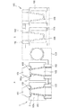
以下、本発明の実施形態について図面を参照しながら説明する。図1は、本発明の一実施形態に係るガラス製品成形装置1を、プレスアンドブロー方式のうちプレス工程の装置に適用した場合の模式図である。本実施形態では、2つの成形型が互いに近接して配置されており、同時に2つのガラス成形品を成形することができるようになっている。同図に示すように、プレスアンドブロー方式は、プレス工程Pとブロー工程Bからなり、プレス工程Pで成形されたパリソン100(ガラス成形品)は、ブロー工程Bに移され当該パリソン100にエアーが吹き込まれてガラスびんが形成される。より詳細に説明すると、プレス工程Pでは、まず第1、第2の粗型2、3に図示しないゴブが投入され、両粗型2、3の上端がバッフル101で閉じられた後、同ゴブが、口型102を通じて押し上げられるプランジャ103にてプレスされ、パリソン100が成形される。このパリソン100は、バッフル101が離脱され両粗型2、3が開放された後、インバートアーム104により口型102を反転させてブロー工程Bで使用される仕上型装置105に移される。仕上型106の中に入れられたパリソン100は、ブローされて製品形状に膨らまされ、ガラスびんとなる。
Hereinafter, embodiments of the present invention will be described with reference to the drawings. FIG. 1 is a schematic view when a glass
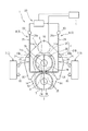
図2は、本実施形態に係るガラス製品成形装置1を表す平面概略図である。このガラス製品成形装置1は、第1、第2の粗型(成形型)2、3と、この粗型2、3を取り囲むように設けられた支持手段4と、粗型を冷却するための冷却機構5と、これら支持手段4及び冷却機構5などを制御する制御部6とで主構成されている。このうち、冷却機構5は、支持手段4の外方に設置されたメイン冷却部7と、支持手段4にその一部が設けられたスポット冷却部8とからなる。なお、以下の説明において、図2紙面貫通方向を上下方向、図2紙面左右方向を左右方向、図2紙面上下方向を前後方向という。
FIG. 2 is a schematic plan view showing the glass
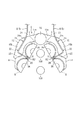
第1、第2の粗型2、3は、同形状かつ同寸法で、上下方向に貫通した筒状に形成されたものであり、図2の前後方向において互いに近接して配置されている。これら両粗型2、3は、いずれも図2左側に位置する第1分割型2A、3Aと、図2右側に位置する第2分割型2B、3Bが組み合わされて構成されたものである。第1、第2の粗型2、3の内周は、図3(a)に示すようにパリソンの所要形状に対応させた形成面9となっている。第1、第2の粗型2、3の外周には溝10が設けられている。この溝10は、第1、第2の粗型2、3の型外側面S(両粗型2、3の近接していない側の面)に形成された外溝10aと、第1、第2の粗型2、3の型内側面U(両粗型2、3の近接している側)に形成された内気道溝10bで構成されている。
The first and second
外溝10aは、第1、第2の粗型2、3の上下方向中央部の所要範囲にわたって形成された周方向に長い6本の周溝11からなる。内気道溝10bは、第1、第2の粗型2、3の上下方向中央部の所要範囲にわたって形成された周方向に長い9本の周溝12と、第1、第2の粗型2、3の周方向内側部の所要範囲にわたって形成された上下方向に長い5本の縦溝13とからなる(図3(b)参照)。内気道溝10bにおいて、上から7本目までの周溝12と5本の縦溝13は交差しており、第1、第2の粗型2、3の型内側面Uの一部が格子状に切り欠かれたようになっている。
The
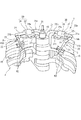
図4は、型開き状態のガラス製品成形装置1の主要部の平面概略図であり、図5は、型開き状態で第1、第2の粗型2、3、後述の型支持部14を取り外したガラス製品成形装置1の主要部の斜視図である。図6は、型開き状態で片方の粗型2を取り外したガラス製品成形装置1の主要部の斜視図である。支持手段4は、第1、第2の粗型2、3を左右方向両側から支持し当該両粗型2、3の外周に沿って型取られた2つの型支持部14、これら型支持部14を動かす2つのアーム部15、及び両アーム部15の片端部15aに設置された軸部16と、両アーム部15を駆動させる図示しない駆動部とを有している。
FIG. 4 is a schematic plan view of the main part of the glass
駆動部の駆動力により、軸部16を回動軸とした両アーム部15の回動が行われ、当該両アーム部15が開方向又は閉方向に付勢されることにより、型支持部14に支持された第1、第2の粗型2、3の型閉じ及び型開きが行われるようになっている。従って、型開きの状態では、図4に示すように一方のアーム部15(左側のアーム部15)と一緒に第1分割型2A、3Aが中央部から左斜め方向へ離れ、他方のアーム部15(右側のアーム部15)と一緒に第2分割型2B、3Bが中央部から右斜め方向へ離れる。
The two
冷却機構5のうちメイン冷却部7は、両アーム部15から離れたところに設置されており(図2参照)、メイン冷却用の図示しない冷却気体発生手段で発生させた冷却気体(エアー)が、当該メイン冷却部7から図2の矢印方向へ向けて吹き出すようになっている。このメイン冷却部7により、第1、第2の粗型2、3、支持手段4の左右両側から冷却気体R1が吹き付けられて、当該両粗型2、3、当該支持手段4の左右方向全体から冷却が行われるようになっている。
The
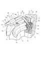
冷却機構5のスポット冷却部8は、冷却気体を発生させるスポット冷却用の冷却気体発生手段20と、この冷却気体発生手段20から第1、第2の粗型2、3の近傍まで冷却気体を送る2つの気体配管21と、各気体配管21に通気可能に連結された各吹付部22とで構成されている(図2参照)。冷却気体発生手段20には、2つの気体取出口23、23が備えられており、各気体取出口23は、支持手段4近傍に設けられている。各気体配管21は可撓性を有するゴムチューブで構成されている。各気体配管21の一端部21aが各気体取出口23に通気可能に連結されており、これら気体配管21は、各気体取出口23から支持手段4の各アーム部15の上面15bに渡って設けられている。
The
各吹付部22は、気体配管21の他端部(管口)21bから第1、第2の粗型2、3間の隙間26の近傍に渡って設けられた金属製の導入管24と、この導入管24に設けられ当該隙間26に入り込む細長状の金属製のノズル25からなる(図5及び図6参照)。導入管24の基端部24aは、気体配管21の他端部(管口)21bに通気可能に連結されている。導入管24の先端部24bは、第1、第2の粗型2、3間の隙間26の方へ向けて曲げられており、当該先端部24bに、ノズル25が設けられている。
Each blowing
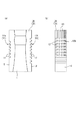
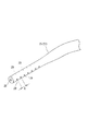
各ノズル25は中途部から先端部に渡ってより細長く形成されており、アーム部15の上側から下斜め方向に向けられて第1、第2の粗型2、3間の隙間26へ導入されている。各ノズル25には、当該ノズル25の先端方向へ向かって冷却気体R2を吹き出す先端孔28及び当該ノズル25の側方に向かって冷却気体R2を吹き出す側孔29が設けられている(図7参照)。このうち側孔29は、ノズル25の先端から向かって左右両側に7つずつ形成されている。本実施形態では、先端孔28、側孔29の孔径は1.5mmとし、隣り合う側孔29間の距離tは10mmとした。なお、これら先端孔28、側孔29の形状、数、孔径、前記距離tは適宜変更することができる。上記先端孔28により、当該先端孔28から吹き出す冷却気体R2は、第1、第2の粗型2、3間の隙間26の斜め下方に向かい、上記左右7つずつの側孔29により当該各側孔29から吹き出す冷却気体R2は、第1、第2の粗型2、3の内気道溝10bが形成された型内側面U、Uに向かうようになっている。
Each
さらに、各ノズル25は、第1、第2の粗型2、3で成形されるガラス成形品100の下側部分100u(図1参照)に対応する当該両粗型2、3の上側部分に対応させ、かつ第1、第2の粗型2、3から離型されたガラス成形品100に冷却気体R2が直接的に当たらないように設けられている。具体的には、各ノズル25の先端25aが、ガラス成形品100の上下方向中央部にくるようにされ、第1、第2の粗型2、3間の隙間26へのノズル25の導入角度αが、下方に55°とされている(図6参照)。なお、各ノズル25とこのノズル25から冷却気体R2を吹き付ける型内側面Uとの距離は、成形条件等により適宜変更されるものである。
Further, each
図5及び図6に示すように、各アーム部15の上面15bには、各吹付部22を固定するための金属製のブラケット30が設けられている。このブラケット30は、平板状に形成された板状部31と、この板状部31の上面31aに設けられた保持部32からなる。板状部31の一側部には凸部31tが形成されており、この凸部31tがボルト33により型支持部14及びアーム部15に取り付けられている。保持部32の下面32aが板状部31の上面31aに溶接で固定されている。また、保持部32には、長手方向に通じる貫通孔32kが形成されており、この貫通孔32kに導入管24が挿通されて固定されている。これにより、導入管24及びノズル25からなる吹付部22が、型支持部14及びアーム部15に対して固定されている。
As shown in FIGS. 5 and 6, a
上記のように、各ノズル25が各アーム部15等に固定されている一方で、各ノズル15に冷却気体R2を送る各気体配管21が可撓性を有しているので、第1、第2の粗型2、3の型閉じ及び型開きが行われた際に、一方のノズル25(図4左側のノズル25)は第1、第2の粗型2、3の第1分割型2A、3Aと一体的に動き、他方のノズル(図4右側のノズル25)は第1、第2の粗型2、3の第2分割型2B、3Bと一体的に動けるようになっている(図4参照)。従って、第1、第2の粗型2、3の型開きが行われ、第1分割型2A、3Aと第2分割型2B、3Bが離間しても、冷却気体R2は両ノズル25、25から吹き出し可能となっている。
As described above, since each
また、支持手段4及び冷却機構5を制御する制御部6により、支持手段4を動かすことによる第1、第2の粗型2、3の型閉じ、型開きのタイミングや、メイン冷却部7による左右両側からのメイン冷却、及びスポット冷却部8による第1、第2の粗型2、3の型内側面U、Uへのスポット冷却の時間やタイミングが適正に制御されている。
Further, by the control unit 6 that controls the
以上のような構成により、冷却気体発生手段20で発生させた冷却気体が、各気体配管21で第1、第2の粗型2、3の近傍まで送られ、送られた当該冷却気体は各吹付部22の導入管24で、第1、第2の粗型2、3間の隙間26の近傍に導入され、当該隙間26へ入り込む各ノズル25により、当該隙間26を隔てて対峙する型内側面U、Uの近傍から当該型内側面U、Uに冷却気体R2が吹き付けられる。さらに、第1、第2の粗型2、3の型内側面U、Uに形成された内気道溝10b、10bにより、型内側面U、Uに吹き付けられた冷却気体R2は縦方向及び周方向に流れる。一方、メイン冷却部7からの冷却気体R1により第1、第2の粗型2、3の全体が冷却される。また、上記内気道溝10b及び第1、第2の粗型2、3の型外側面S、Sに形成された外溝10aにより両粗型2、3の放熱効率をも向上されている。
With the configuration as described above, the cooling gas generated by the cooling gas generating means 20 is sent to the vicinity of the first and second
第1、第2の粗型2、3の型閉じ状態では(図2参照)、第1、第2の粗型2、3間の隙間26の左右両側からノズル25、25が入り込み、第1の粗型2の型内側面U及び第2の粗型3の型内側面Uに冷却気体R2が吹き付けられる。一方、第1、第2の粗型2、3の型開き状態或いは、型閉じから型開きの状態では(図4参照)、一方のノズル25(図4左側)により、第1の粗型2の第1分割型2Aの型内側面U、及び第2の粗型3の第1分割型3Aの型内側面Uに冷却気体R2が吹き付けられ、他方のノズル25(図4右側)により、第1の粗型2の第2分割型2Bの型内側面U、及び第2の粗型3の第2分割型3Bの型内側面Uに冷却気体R2が吹き付けられる。つまり、第1、第2の粗型2、3の型閉じ、型開き状態、或いは型閉じ状態から型開き状態のいずれのときでも、型内側面Uに冷却気体R2が吹き付けられ、第1、第2の粗型2、3の内肉部35が効果的に冷却される。
In the closed state of the first and second
上記本実施形態のガラス製品成形装置1とすれば、スポット冷却部8により、第1、第2の粗型2、3間の隙間26を隔てて対峙する型内側面U、Uの近傍から当該型内側面U、Uに冷却気体R2を吹き付けて冷却するため、成形型の内部に冷却通路を形成しなくても、十分な冷却効率を得ることができる。そのため、成形型の内部に冷却通路を形成する場合よりも、冷却気体を送るための配管等の部品が少なくなり、成形装置を構築しやすい。
If it is set as the glass product shaping |
また、各成形型を加工する必要もなく、メンテナンスは少ない手間ですむので、コストを抑えることができる。さらに、各成形型の内部に空洞部を形成する必要はないため、当該各成形型の強度を低下させることがない。そして、冷却気体R2は第1、第2の粗型2、3の周囲に吹き付けられ、当該両粗型2、3の内肉部35(内部)はゆるやかに冷やされるため、ガラス成形品100に悪影響を及ぼさず、バッフルマークのずれが発生し難い。これにより、ガラス製品の強度を向上させることができる。
In addition, it is not necessary to process each mold, and maintenance can be performed with less labor, thus reducing costs. Furthermore, since it is not necessary to form a cavity inside each mold, the strength of each mold is not reduced. And since the cooling gas R2 is sprayed around the 1st, 2nd
また、第1、第2の粗型2、3の型内側面U、Uに形成された内気道溝10b、10bにより、型内側面U、Uに吹き付けられた冷却気体R2は縦方向及び周方向に流れるので、当該冷却気体R2は多方向へ拡散させられ、当該冷却気体R2による冷却効率を向上させることができる。冷却気体R2は、第1、第2の粗型2、3の型閉じ、型開き状態、或いは型閉じ状態から型開き状態のいずれのときにおいても、ノズル25、25から吹き出し可能となっており、型内側面U、Uの近傍から当該型内側面U、Uに冷却気体R2が吹き付けられて冷却されるため、冷却するタイミングや冷却時間に制約がなくなり、よりきめ細かい冷却パターンでガラス成形品を成形することができる。これにより、ガラス製品の品質をさらに向上させることができる。
Further, the cooling air R2 blown to the inner surfaces U and U of the molds by the
冷却機構5のうちスポット冷却部8は、冷却気体を発生させる冷却気体発生手段20と、冷却気体を送る気体配管21と、冷却気体を第1、第2の粗型2、3間の隙間26に導入し型内側面U、Uに吹き付ける吹付部22だけで構成することができるので、少ないスペースで設置でき、装置周辺に設けられた他部材に制約されることがない。
The
各吹付部22のノズル25には、当該ノズル25の先端方向へ向かって冷却気体R2を吹き出す先端孔28及び当該ノズル25の側方に向かって冷却気体R2を吹き出す側孔29が設けられているので、第1、第2の粗型2、3の型内側面U、Uの近傍から当該型内側面U、Uのより大きな範囲に渡って冷却気体R2を吹き付けることができる。さらに、各ノズル25が、第1、第2の粗型2、3で成形されるガラス成形品100の下側部分100uに対応する当該両粗型2、3の上側部分に対応させて設けられていることで、ガラス成形品100の下側部分100uから冷却することができる。これにより、ガラス成形品100の下側部分(底部を含む)100uが効果的に冷却され、バッフルマークのずれを防止することができる。また、各ノズル25が、第1、第2の粗型2、3から離型されたガラス成形品100に冷却気体R2が直接的に当たらないように設けられていることにより、離型されたガラス成形品100に冷却気体R2が直接的に当たることによる影響を抑えることができる。
The
上記本実施形態のガラス製品成形装置1は、同時に2つのガラス成形品を成形するために互いに近接して配置された成形型を、冷却気体により冷却する成形型の冷却方法を実施するための装置の一例である。上記ガラス製品成形装置1を用いた成形型の冷却方法は、第1、第2の粗型2、3間の隙間26を隔てて対峙する型内側面U、Uの近傍から、当該型内側面U、Uにノズル25、25から吹き出る冷却気体R2を吹き付けて当該第1、第2の粗型2、3を冷却するものである。
The glass
このような成形型の冷却方法とすれば、第1、第2の粗型2、3間の隙間26を隔てて対峙する型内側面U、Uの近傍から当該型内側面U、Uに冷却気体R2を吹き付けて冷却するため、成形型の内部に冷却通路を形成しなくても、十分な冷却効率を得ることができる。そのため、成形型の内部に冷却通路を形成する場合よりも、冷却気体を送るための配管等の部品が少なくなり、成形装置を構築しやすい。
With such a mold cooling method, the mold inner surfaces U and U are cooled from the vicinity of the mold inner surfaces U and U facing each other with a
また、各成形型を加工する必要もなく、メンテナンスは少ない手間ですむので、コストを抑えることができる。さらに、各成形型の内部に空洞部を形成する必要はないため、当該各成形型の強度を低下させることがない。そして、冷却気体R2は第1、第2の粗型2、3の周囲に吹き付けられ、当該両粗型2、3の内肉部(内部)35はゆるやかに冷やされるため、ガラス成形品100に悪影響を及ぼさず、バッフルマークのずれが発生し難い。これにより、ガラス製品の強度を向上させることができる。
In addition, it is not necessary to process each mold, and maintenance can be performed with less labor, thus reducing costs. Furthermore, since it is not necessary to form a cavity inside each mold, the strength of each mold is not reduced. And since the cooling gas R2 is sprayed around the 1st, 2nd
なお、上記で開示した実施形態は例示であり、制限的なものではない。本実施形態では、プレスアンドブロー方式のうちのプレス工程で用いられる装置に本発明を適用したが、同方式のブロー工程や、ブローアンドブロー方式の各ブロー工程で用いられる装置に本発明を適用してもよい。同時に3つ以上のガラス成形品を成形するために互いに近接して配置された3つ以上の成形型を備えるガラス製品成形装置としてもよい。例えば、3つの成形型を備える場合には、3つの成形型を直線状に並べて2つの隙間にノズルを配置することや、3つの成形型を放射状に並べて3つの隙間にノズルを配置することが挙げられる。
The embodiment disclosed above is an example and is not restrictive. In the present embodiment, the present invention is applied to an apparatus used in a press process of the press and blow method, but the present invention is applied to an apparatus used in the same blow process and each blow process of the blow and blow system. May be. It is good also as a glass product shaping | molding apparatus provided with the 3 or more shaping | molding die arrange | positioned mutually close in order to shape |
スポット冷却部の一例として、冷却気体発生手段、気体配管及び吹付部からなる本実施形態のものを挙げたが、他の構成を採用することもできる。また、成形型の型内側面に形成された気道溝として、多様な形態をとることができる。縦溝及び周溝の数、位置、長さ、幅を変更することや、斜め方向に形成された斜溝のみ、或いは当該斜溝、縦溝及び周溝を組み合わせてもよい。 Although the thing of this embodiment which consists of a cooling gas generation means, gas piping, and a spraying part was mentioned as an example of a spot cooling part, another structure is also employable. Further, the airway groove formed on the inner surface of the mold can take various forms. The number, position, length, and width of the longitudinal grooves and circumferential grooves may be changed, or only the oblique grooves formed in the oblique direction, or the oblique grooves, the longitudinal grooves, and the circumferential grooves may be combined.
成形型の構成や、成形型の周辺機材の構成も勿論、適宜変更することができる。ノズルの形状、長さ、角度、位置等も適宜変更することができる。なお、本発明の範囲は、上記した実施形態に限定されるものではなく、特許請求の範囲によって示され、特許請求の範囲と均等の意味及び範囲内の全ての変更が含まれる。 Of course, the configuration of the mold and the configuration of the peripheral equipment of the mold can be appropriately changed. The shape, length, angle, position, etc. of the nozzle can also be changed as appropriate. Note that the scope of the present invention is not limited to the above-described embodiment, but is defined by the scope of the claims, and includes meanings equivalent to the scope of the claims and all modifications within the scope.
1 ガラス製品成形装置
2 第1の粗型
2A 第1分割型
2B 第2分割型
3 第2の粗型
3A 第1分割型
3B 第2分割型
4 支持手段
7 メイン冷却部
8 スポット冷却部
10a 外溝
10b 内気道溝
12 周溝
13 縦溝
20 冷却気体発生手段
21 気体配管
22 吹付部
24 導入管
25 ノズル
26 隙間
35 内肉部
R1 冷却気体
R2 冷却気体
U 型内側面
α 導入角度
DESCRIPTION OF
Claims (9)
前記冷却機構は、前記複数の成形型間の隙間を隔てて対峙する型内側面の近傍から当該型内側面に前記冷却気体を吹き付けるスポット冷却部を備えていることを特徴とするガラス製品成形装置。 In a glass product forming apparatus having a plurality of molds arranged close to each other to form a plurality of glass molded articles at the same time, and a cooling mechanism for cooling the plurality of molds with a cooling gas,
The cooling mechanism includes a spot cooling unit that blows the cooling gas to the inner surface of the mold from the vicinity of the inner surface of the mold facing the gaps between the plurality of molds. .
前記スポット冷却部は、当該各成形型が開状態から閉状態のいずれのときにも当該各成形型の型内側面の近傍から当該型内側面に前記冷却気体を吹き付け可能に構成されていることを特徴とする請求項1又は2に記載のガラス製品成形装置。 Each of the molding dies is configured by combining a plurality of divided dies so that they can be freely opened and closed.
The spot cooling unit is configured to be able to spray the cooling gas onto the inner surface of the mold from the vicinity of the inner surface of the mold when the molding die is in an open state or a closed state. The glass product forming apparatus according to claim 1 or 2.
前記複数の成形型間の隙間を隔てて対峙する型内側面の近傍から、当該型内側面に前記冷却気体を吹き付けて当該各成形型を冷却することを特徴とする成形型の冷却方法。 In a cooling method of a molding die in which a plurality of molding dies arranged close to each other to form a plurality of glass moldings at the same time are cooled by a cooling gas,
A cooling method of a molding die, wherein the respective molding dies are cooled by blowing the cooling gas onto the inner side surface of the die from the vicinity of the inner side surface of the die facing each other with a gap between the plurality of molding dies.
Priority Applications (1)
| Application Number | Priority Date | Filing Date | Title |
|---|---|---|---|
| JP2009296704A JP5606733B2 (en) | 2009-12-28 | 2009-12-28 | Glass product forming equipment |
Applications Claiming Priority (1)
| Application Number | Priority Date | Filing Date | Title |
|---|---|---|---|
| JP2009296704A JP5606733B2 (en) | 2009-12-28 | 2009-12-28 | Glass product forming equipment |
Publications (2)
| Publication Number | Publication Date |
|---|---|
| JP2011136853A true JP2011136853A (en) | 2011-07-14 |
| JP5606733B2 JP5606733B2 (en) | 2014-10-15 |
Family
ID=44348679
Family Applications (1)
| Application Number | Title | Priority Date | Filing Date |
|---|---|---|---|
| JP2009296704A Expired - Fee Related JP5606733B2 (en) | 2009-12-28 | 2009-12-28 | Glass product forming equipment |
Country Status (1)
| Country | Link |
|---|---|
| JP (1) | JP5606733B2 (en) |
Cited By (2)
| Publication number | Priority date | Publication date | Assignee | Title |
|---|---|---|---|---|
| WO2014156941A1 (en) * | 2013-03-26 | 2014-10-02 | 日本山村硝子株式会社 | Parison forming device |
| CN115594391A (en) * | 2022-10-26 | 2023-01-13 | 安徽省大诚智能玻璃有限公司(Cn) | Cooling device for optical glass processing |
Citations (6)
| Publication number | Priority date | Publication date | Assignee | Title |
|---|---|---|---|---|
| JPS5415285B2 (en) * | 1974-02-11 | 1979-06-13 | ||
| JPS5511614B2 (en) * | 1975-07-07 | 1980-03-26 | ||
| JPS58657Y2 (en) * | 1978-04-12 | 1983-01-07 | 石塚硝子株式会社 | Mold cooling device in glass molding machine |
| JPS62260725A (en) * | 1986-04-18 | 1987-11-13 | エムハート・グラス・マシーナリー・インベストメンツ・インコーポレーテッド | Glass vessel forming device |
| JPS63140034U (en) * | 1987-03-03 | 1988-09-14 | ||
| JP2004299942A (en) * | 2003-03-31 | 2004-10-28 | Nihon Yamamura Glass Co Ltd | Blank mold for use in bottle making machine |
-
2009
- 2009-12-28 JP JP2009296704A patent/JP5606733B2/en not_active Expired - Fee Related
Patent Citations (6)
| Publication number | Priority date | Publication date | Assignee | Title |
|---|---|---|---|---|
| JPS5415285B2 (en) * | 1974-02-11 | 1979-06-13 | ||
| JPS5511614B2 (en) * | 1975-07-07 | 1980-03-26 | ||
| JPS58657Y2 (en) * | 1978-04-12 | 1983-01-07 | 石塚硝子株式会社 | Mold cooling device in glass molding machine |
| JPS62260725A (en) * | 1986-04-18 | 1987-11-13 | エムハート・グラス・マシーナリー・インベストメンツ・インコーポレーテッド | Glass vessel forming device |
| JPS63140034U (en) * | 1987-03-03 | 1988-09-14 | ||
| JP2004299942A (en) * | 2003-03-31 | 2004-10-28 | Nihon Yamamura Glass Co Ltd | Blank mold for use in bottle making machine |
Cited By (6)
| Publication number | Priority date | Publication date | Assignee | Title |
|---|---|---|---|---|
| WO2014156941A1 (en) * | 2013-03-26 | 2014-10-02 | 日本山村硝子株式会社 | Parison forming device |
| CN105228960A (en) * | 2013-03-26 | 2016-01-06 | 日本山村硝子株式会社 | parison forming device |
| EP2980032A4 (en) * | 2013-03-26 | 2016-12-28 | Nihon Yamamura Glass Co Ltd | DEVICE FOR FORMING A PARAISON |
| JPWO2014156941A1 (en) * | 2013-03-26 | 2017-02-16 | 日本山村硝子株式会社 | Parison molding equipment |
| CN115594391A (en) * | 2022-10-26 | 2023-01-13 | 安徽省大诚智能玻璃有限公司(Cn) | Cooling device for optical glass processing |
| CN115594391B (en) * | 2022-10-26 | 2023-11-14 | 安徽省大诚智能玻璃有限公司 | Cooling device for optical glass processing |
Also Published As
| Publication number | Publication date |
|---|---|
| JP5606733B2 (en) | 2014-10-15 |
Similar Documents
| Publication | Publication Date | Title |
|---|---|---|
| JP4864794B2 (en) | Mold Cooling System for I.S. Machines | |
| JP2010202509A (en) | Float bath system for producing float glass and cooling method thereof | |
| JP2010053034A (en) | Multi-gob type i.s. glassware forming machine | |
| JP5606733B2 (en) | Glass product forming equipment | |
| JP6243182B2 (en) | Biaxial cooling system and method | |
| JPS59199535A (en) | Casting device for glass vessel producer | |
| JPH0416413B2 (en) | ||
| JP2014509582A (en) | Method and apparatus for producing thin hollow glass products | |
| JP6843142B2 (en) | Mold cooling methods and systems for glassware molding machines | |
| JPH072529A (en) | Metal die cooler for glassware molding machine | |
| CN108237181B (en) | Forming device | |
| US9475721B2 (en) | Apparatus and method for manufacturing glass optical element | |
| US2928214A (en) | Cooling system for glass forming molds | |
| CN208038292U (en) | A kind of mould for glass bottle uniformly cooled down | |
| JP4372949B2 (en) | Vacuum mechanism of I.S. machine | |
| CN101351413B (en) | Neck cooling device for a glassware manufacturing plant and method for cooling a glassware finish during preforming in a glassware manufacturing plant | |
| ITMI20000400A1 (en) | MOLD OPENING AND CLOSING MECHANISM FOR AN I.S. MACHINE | |
| JP4450801B2 (en) | Glass lump forming apparatus, glass lump manufacturing method, and optical element manufacturing method | |
| JP2001328824A (en) | Guide ring | |
| JP2010070390A (en) | Mold device for glass vessel molding apparatus | |
| CN217351171U (en) | Electronic control gas distribution system of bubble blowing machine | |
| JP4655685B2 (en) | Optical fiber drawing furnace and optical fiber drawing method | |
| JP2004323349A (en) | Mold support mechanism for i.s. machine | |
| JP2005047720A (en) | Method and apparatus for cooling rough form of bottle-making machine | |
| JP2004231487A (en) | Apparatus for cooling bottom mold for glass molding, and glass molding device using the same |
Legal Events
| Date | Code | Title | Description |
|---|---|---|---|
| A621 | Written request for application examination |
Free format text: JAPANESE INTERMEDIATE CODE: A621 Effective date: 20121218 |
|
| A977 | Report on retrieval |
Free format text: JAPANESE INTERMEDIATE CODE: A971007 Effective date: 20131016 |
|
| A131 | Notification of reasons for refusal |
Free format text: JAPANESE INTERMEDIATE CODE: A131 Effective date: 20131108 |
|
| A521 | Request for written amendment filed |
Free format text: JAPANESE INTERMEDIATE CODE: A523 Effective date: 20131204 |
|
| TRDD | Decision of grant or rejection written | ||
| A01 | Written decision to grant a patent or to grant a registration (utility model) |
Free format text: JAPANESE INTERMEDIATE CODE: A01 Effective date: 20140820 |
|
| A61 | First payment of annual fees (during grant procedure) |
Free format text: JAPANESE INTERMEDIATE CODE: A61 Effective date: 20140827 |
|
| R150 | Certificate of patent or registration of utility model |
Ref document number: 5606733 Country of ref document: JP Free format text: JAPANESE INTERMEDIATE CODE: R150 |
|
| R250 | Receipt of annual fees |
Free format text: JAPANESE INTERMEDIATE CODE: R250 |
|
| R250 | Receipt of annual fees |
Free format text: JAPANESE INTERMEDIATE CODE: R250 |
|
| R250 | Receipt of annual fees |
Free format text: JAPANESE INTERMEDIATE CODE: R250 |
|
| R250 | Receipt of annual fees |
Free format text: JAPANESE INTERMEDIATE CODE: R250 |
|
| R250 | Receipt of annual fees |
Free format text: JAPANESE INTERMEDIATE CODE: R250 |
|
| LAPS | Cancellation because of no payment of annual fees |