JP2011136829A - Image recording device - Google Patents
Image recording device Download PDFInfo
- Publication number
- JP2011136829A JP2011136829A JP2009299264A JP2009299264A JP2011136829A JP 2011136829 A JP2011136829 A JP 2011136829A JP 2009299264 A JP2009299264 A JP 2009299264A JP 2009299264 A JP2009299264 A JP 2009299264A JP 2011136829 A JP2011136829 A JP 2011136829A
- Authority
- JP
- Japan
- Prior art keywords
- guide plate
- tray
- image recording
- paper feed
- main body
- Prior art date
- Legal status (The legal status is an assumption and is not a legal conclusion. Google has not performed a legal analysis and makes no representation as to the accuracy of the status listed.)
- Granted
Links
- 230000007246 mechanism Effects 0.000 claims description 26
- 230000004044 response Effects 0.000 claims description 2
- 238000000926 separation method Methods 0.000 description 7
- 230000005540 biological transmission Effects 0.000 description 6
- 230000004048 modification Effects 0.000 description 5
- 238000012986 modification Methods 0.000 description 5
- 230000001105 regulatory effect Effects 0.000 description 5
- 239000000463 material Substances 0.000 description 3
- 230000004308 accommodation Effects 0.000 description 2
- 238000010586 diagram Methods 0.000 description 2
- 238000003780 insertion Methods 0.000 description 2
- 230000037431 insertion Effects 0.000 description 2
- 238000013459 approach Methods 0.000 description 1
- 230000001276 controlling effect Effects 0.000 description 1
- 238000013461 design Methods 0.000 description 1
- 230000000694 effects Effects 0.000 description 1
- 238000000034 method Methods 0.000 description 1
- 238000003825 pressing Methods 0.000 description 1
- 230000008569 process Effects 0.000 description 1
- 239000011347 resin Substances 0.000 description 1
- 229920005989 resin Polymers 0.000 description 1
- 229910052710 silicon Inorganic materials 0.000 description 1
- 239000010703 silicon Substances 0.000 description 1
Images
Landscapes
- Separation, Sorting, Adjustment, Or Bending Of Sheets To Be Conveyed (AREA)
- Conveyance By Endless Belt Conveyors (AREA)
- Feeding Of Articles By Means Other Than Belts Or Rollers (AREA)
- Handling Of Sheets (AREA)
Abstract
【課題】画像記録部とトレイとの間に設けられた搬送路でシート部材が詰まった場合でも、シート部材を容易に除去することが可能な画像記録装置を提供すること。
【解決手段】画像記録部24と給紙トレイ78との間に下側ガイド部材90が設けられている。下側ガイド部材90は、前方側の前方ガイド板91と、後方側の後方ガイド板92と、これらを回動可能に支持する回動軸93とを有する。給紙トレイ78が未装着のときは、前方ガイド板91の前方端及び後方ガイド板92の後方端は、下方へ下がっており、そのため、反転搬送路67におけるジャム処理が容易となる。給紙トレイ78が装着されると、給紙トレイ78によって各ガイド板91,92が上方へ押し上げられて、反転搬送路67が形成される。
【選択図】図2To provide an image recording apparatus capable of easily removing a sheet member even when the sheet member is jammed in a conveyance path provided between an image recording unit and a tray.
A lower guide member 90 is provided between an image recording unit 24 and a paper feed tray 78. The lower guide member 90 includes a front guide plate 91 on the front side, a rear guide plate 92 on the rear side, and a rotation shaft 93 that rotatably supports these. When the paper feed tray 78 is not attached, the front end of the front guide plate 91 and the rear end of the rear guide plate 92 are lowered downward, so that jam processing in the reverse conveyance path 67 is facilitated. When the paper feed tray 78 is mounted, the guide plates 91 and 92 are pushed upward by the paper feed tray 78 to form the reverse conveyance path 67.
[Selection] Figure 2
Description
本発明は、シート部材の両面に画像を記録する画像記録装置に関し、特に、画像記録部を通過したシート部材をスイッチバックさせて再び画像記録部へ戻す搬送経を有する画像記録装置に関する。 The present invention relates to an image recording apparatus that records images on both sides of a sheet member, and more particularly, to an image recording apparatus having a conveyance path for switching back a sheet member that has passed through an image recording unit and returning it to the image recording unit again.
従来より、記録用紙(シート部材)の両面に画像を記録可能な画像記録装置が知られている。特許文献1及び特許文献2には、装置のコンパクト化を実現するために、シートトレイの上側に画像記録部が設けられ、シートトレイと画像記録部とが湾曲状の搬送路で接続された画像記録装置が開示されている。この種の画像記録装置では、両面画像記録を行う場合に、画像記録部を通過した記録用紙をスイッチバックさせて再びシートトレイに搬送し、その記録用紙を給送ローラで再び画像記録部に搬送する機構が採用されている(特許文献1及び2参照)。これにより、シートトレイから給紙するときに通る搬送路をスイッチバック後に案内される搬送経路として兼用できるため、装置の薄型化が実現される。
Conventionally, an image recording apparatus capable of recording images on both sides of a recording sheet (sheet member) is known. In
また、オフィスなどに広く普及している大型で自立型の複写装置(コピー機)では、高さ寸法が制約されないため、給紙時に通る搬送路とは別に、画像記録部とシートトレイとの間にスイッチバック用の搬送路が設けられている。この複写装置では、画像記録部を通過した記録用紙は、スイッチバックされた後に上記スイッチバック用の搬送路を通って再び画像記録部へ搬送される。 In addition, a large and self-supporting copying machine (copier) that is widely used in offices and the like is not limited in height, so that it is located between the image recording unit and the sheet tray separately from the conveyance path through which paper is fed. Is provided with a transport path for switchback. In this copying apparatus, the recording paper that has passed through the image recording section is switched back and then transported again to the image recording section through the switchback transport path.
しかしながら、特許文献1及び2に記載の画像記録装置では、スイッチバック後の記録用紙が給送ローラによって搬送される際に、画像記録面に給送ローラが当接する。そのため、給紙ローラの接触によって画像記録面が汚れるおそれがある。また、画像記録面に付着した記録材(インクやトナー等)が給紙ローラに付着することもあり、この付着した記録材が給紙ローラによって給紙される次の記録用紙に移り、記録用紙を汚すおそれもある。一方、上述した大型の複写装置で採用されているように、給紙時の搬送路とは別の搬送路を設けると上記問題は解決できる。しかしながら、装置の薄型化という社会的要請に応えるために、画像記録部とシートトレイとの間に余分なスペースができないように設計し、装置の高さを限りなくコンパクトにした場合は、仮に上記別の搬送路で記録用紙が詰まると、詰まった記録用紙を除去する作業が極めて困難になる。
However, in the image recording apparatuses described in
そこで、本発明は上記問題に鑑みてなされたものであり、画像記録部とトレイとの間に設けられた搬送路でシート部材が詰まった場合でも、シート部材を容易に除去することが可能な画像記録装置を提供することにある。 Therefore, the present invention has been made in view of the above problems, and even when the sheet member is jammed in the conveyance path provided between the image recording unit and the tray, the sheet member can be easily removed. An object is to provide an image recording apparatus.
(1) 本発明は、トレイと、画像記録部と、背面カバーと、ガイド部材と、回動軸と、付与手段と、第1支持機構と、第2支持機構とを具備する画像記録装置として構成されている。トレイは、装置本体の正面から該装置本体に対して挿抜可能に設けられている。このトレイに、画像が記録されるシート部材が保持される。画像記録部は、上記トレイの上側に設けられている。背面カバーは、上記装置本体の背面に開閉可能に設けられている。この背面カバーは、装置本体の背面に対して閉じられた状態で上記トレイから上記画像記録部に至る湾曲状の湾曲搬送路を形成し、開けられた状態で上記湾曲搬送路を開放する。ガイド部材は、上記トレイと上記画像記録部との間に設けられた第1ガイド板及び第2ガイド板を有する。このガイド部材は、上記画像記録部を通過したシート部材を上記第2ガイド板及び上記第1ガイド板を順次経て上記湾曲搬送路へ案内する。回動軸は、正面側の端部を回動自由端として上記第2ガイド板を回動自在に支持するとともに、背面側の端部を回動自由端として上記第1ガイド板を回動自在に支持する。付与手段は、上記第2ガイド板に作用する下方へのモーメントよりも上記第1ガイド板に作用する下方へのモーメントが大きくなるように上記第1ガイド板に下方への付勢力を付与する。第1支持機構は、上記トレイが上記装置本体に挿入されたことに応じて、上記湾曲搬送路へのシート部材の案内が可能な第1姿勢となるように上記モーメントに抗して上記ガイド部材を支持する。また、第2支持機構は、上記トレイが上記装置本体から脱抜されたときに上記第1支持機構による支持が解除されて下方へ回動した上記各ガイド板が所定角度をなす第2姿勢となるように上記ガイド部材を支持する。 (1) The present invention is an image recording apparatus including a tray, an image recording unit, a back cover, a guide member, a rotating shaft, an applying unit, a first support mechanism, and a second support mechanism. It is configured. The tray is provided so that it can be inserted into and removed from the apparatus main body from the front of the apparatus main body. A sheet member on which an image is recorded is held on the tray. The image recording unit is provided on the upper side of the tray. The back cover is provided on the back surface of the apparatus main body so as to be opened and closed. The back cover forms a curved curved conveyance path from the tray to the image recording unit in a state of being closed with respect to the back surface of the apparatus main body, and opens the curved conveyance path in an opened state. The guide member has a first guide plate and a second guide plate provided between the tray and the image recording unit. The guide member guides the sheet member that has passed through the image recording unit to the curved conveyance path sequentially through the second guide plate and the first guide plate. The rotation shaft rotatably supports the second guide plate with the front end as a rotation free end, and the first guide plate with the back end as a rotation free end. To support. The applying means applies a downward biasing force to the first guide plate so that a downward moment acting on the first guide plate is larger than a downward moment acting on the second guide plate. The first support mechanism resists the moment so as to be in a first posture capable of guiding the sheet member to the curved conveyance path in response to the insertion of the tray into the apparatus main body. Support. Further, the second support mechanism has a second posture in which each of the guide plates rotated downward by releasing the support by the first support mechanism when the tray is removed from the apparatus main body has a predetermined angle. The guide member is supported so as to be.
このように構成されているため、画像記録部とトレイとの間に、上記ガイド部材によって搬送路(以下「反転搬送路」という。)が形成される。この反転搬送路は、画像記録部を通過したシート部材を湾曲搬送路へ案内するためのものである。トレイが装置本体から抜き出されると、ガイド部材が第1支持機構によって支持されなくなる。このとき、回動軸を中心にして第1ガイド板がその自重と上記付与手段による付勢力とによって下方へ回動する。これにより、上記反転搬送路の背面側が高さ方向に拡げられる。このため、上記反転搬送路でシート部材が詰まった場合でも、背面カバーを開ければ、詰まったシート部材に容易にアクセスすることができるので、シート部材の除去作業が容易となる。また、回動軸を中心にして第2ガイド板がその自重によって下方へ回動する。これにより、上記反転搬送路の正面側が高さ方向に拡げられる。このため、上記反転搬送路でシート部材が詰まった場合でも、トレイが抜き出された正面側から詰まったシート部材に容易にアクセスすることができるので、シート部材の除去作業が容易となる。 Due to such a configuration, a conveyance path (hereinafter referred to as “reverse conveyance path”) is formed by the guide member between the image recording unit and the tray. This reverse conveyance path is for guiding the sheet member that has passed through the image recording section to the curved conveyance path. When the tray is extracted from the apparatus main body, the guide member is not supported by the first support mechanism. At this time, the first guide plate is rotated downward about its rotation axis by its own weight and the urging force of the applying means. Thereby, the back side of the reversing conveyance path is expanded in the height direction. For this reason, even when the sheet member is jammed in the reversal conveyance path, the jammed sheet member can be easily accessed by opening the back cover, so that the sheet member can be easily removed. Further, the second guide plate is rotated downward by its own weight around the rotation axis. Thereby, the front side of the reversal conveyance path is expanded in the height direction. For this reason, even when the sheet member is jammed in the reverse conveyance path, the jammed sheet member can be easily accessed from the front side from which the tray is extracted, so that the sheet member can be easily removed.
(2) 本発明の画像記録装置は、搬送ローラ対を更に備えている。この搬送ローラ対は、上下方向に圧接された2つのローラからなり、上記ガイド部材によって案内されるシート部材を上記湾曲搬送路へ向けて搬送する。また、上記搬送ローラ対のいずれか一方のローラが上記回動軸によって回動可能に支持されている。 (2) The image recording apparatus of the present invention further includes a pair of conveyance rollers. The pair of conveying rollers includes two rollers pressed in the vertical direction, and conveys the sheet member guided by the guide member toward the curved conveying path. One of the rollers of the conveying roller pair is rotatably supported by the rotation shaft.
これにより、ローラを軸支する支軸として上記回動軸を兼用できるので、装置をよりコンパクトにすることができる。また、搬送ローラ対が位置する部分を支点として第1ガイド板の背面側の端部が下方へ下がり、第2ガイド板の正面側の端部が下方へ下がる。このため、搬送ローラ対によって挟まれた状態でシート部材が詰まった場合でも、装置本体の正面側及び背面側のいずれからでもシート部材を容易に取り除くことが可能となる。 Thereby, since the said rotating shaft can be combined as a spindle which supports a roller, an apparatus can be made more compact. Further, with the portion where the conveying roller pair is located as a fulcrum, the end portion on the back side of the first guide plate is lowered and the end portion on the front side of the second guide plate is lowered. For this reason, even when the sheet member is jammed while being sandwiched between the pair of conveying rollers, the sheet member can be easily removed from either the front side or the back side of the apparatus main body.
(3) 上記所定角度は、上記トレイが上記装置本体から脱抜された状態で、上記第2ガイド板の正面側の端部が上記装置本体の底面から離間した位置で静止可能な角度であることが好ましい。 (3) The predetermined angle is an angle at which the front end portion of the second guide plate can be stopped at a position away from the bottom surface of the apparatus body in a state where the tray is removed from the apparatus body. It is preferable.
装置本体からトレイが抜き出されると、まず最初に第1ガイド板の支持が無くなるため、第1ガイド板が下方へ回動して所定位置に到達する。その後、第2ガイド板の支持が無くなり、第2ガイド板が下方へ回動する。このとき、上記付与手段によって第1ガイド板に下方への付勢力が付与されているため、第1ガイド板は上記第2姿勢となるまでは単独で下方へ回動するが、上記第2姿勢となったときに第1ガイド板と第2ガイド板とが上記第2支持機構によって互いに支持される。第1ガイド板には第2ガイド板よりも大きなモーメントが作用している。そのため、第2ガイド板は、その自重よりも大きな力で持ち上げられて、装置本体の底面から離間した位置で静止する。これにより、トレイが抜き出されても、第2ガイド板が装置本体の底面に衝突しなくなる。したがって、トレイへの衝突による第2ガイド板の損壊が防止され、しかも、衝突音が抑制される。 When the tray is extracted from the apparatus main body, first, the first guide plate is not supported, so the first guide plate rotates downward and reaches a predetermined position. Thereafter, the support of the second guide plate is lost, and the second guide plate rotates downward. At this time, since the downward biasing force is applied to the first guide plate by the applying means, the first guide plate rotates independently until it reaches the second posture. At this time, the first guide plate and the second guide plate are supported by the second support mechanism. A larger moment acts on the first guide plate than on the second guide plate. Therefore, the second guide plate is lifted by a force larger than its own weight and stops at a position separated from the bottom surface of the apparatus main body. Thereby, even if the tray is extracted, the second guide plate does not collide with the bottom surface of the apparatus main body. Therefore, the second guide plate is prevented from being damaged due to the collision with the tray, and the collision sound is suppressed.
(4) 本発明の画像記録装置は、上記トレイに保持されたシート部材を上記湾曲搬送路へ給送する給送ローラを更に備えている。この給送ローラは、上記トレイと上記ガイド部材との間に設けられている。また、給送ローラのローラ面には弾性部材が設けられている。この構成において、上記第1ガイド板は、上記トレイが上記装置本体から脱抜されたときに下方へ回動し、上記給送ローラのローラ面に当接することによって静止する。 (4) The image recording apparatus of the present invention further includes a feeding roller that feeds the sheet member held on the tray to the curved conveyance path. The feeding roller is provided between the tray and the guide member. An elastic member is provided on the roller surface of the feeding roller. In this configuration, the first guide plate rotates downward when the tray is removed from the apparatus main body, and comes to rest by contacting the roller surface of the feeding roller.
これにより、上記第1ガイド板が下方へ下がって給送ローラに衝突しても、弾性部材によってその衝撃が吸収されるので、衝突音が抑制される。 Thereby, even if the first guide plate is lowered and collides with the feeding roller, the impact is absorbed by the elastic member, so that the collision noise is suppressed.
(5) 上記第1支持機構の具体的な構成としては、第1係合部と、第1支持部と、第2係合部と、第2支持部とにより構成された機構が考えられる。第1係合部は、上記第1ガイド板の下面に設けられている。第1支持部は、上記トレイが上記装置本体に装着されたときに上記第1係合部と係合して上記第1ガイド板を下側から持ち上げるように支持する。第2係合部は、上記第2ガイド板の下面に設けられている。第2支持部は、上記トレイが上記装置本体に装着されたときに上記第2係合部と係合して上記第2ガイド板を下側から持ち上げるように支持する。 (5) As a specific configuration of the first support mechanism, a mechanism including a first engagement portion, a first support portion, a second engagement portion, and a second support portion can be considered. The first engaging portion is provided on the lower surface of the first guide plate. The first support part is engaged with the first engagement part when the tray is mounted on the apparatus main body, and supports the first guide plate to be lifted from below. The second engaging portion is provided on the lower surface of the second guide plate. The second support portion supports the second guide plate to be lifted from below by engaging with the second engagement portion when the tray is mounted on the apparatus main body.
(6) 上記第2支持機構の具体的な構成としては、上記各ガイド板のいずれか一方のガイド板における上記回動軸付近からから突出した突出片を有する機構が考えられる。この突出片の先端が他方のガイド板に当接することにより各ガイド板がなす角度が上記所定角度に維持される。 (6) As a specific configuration of the second support mechanism, a mechanism having a protruding piece protruding from the vicinity of the rotation shaft of one of the guide plates is conceivable. The angle formed by each guide plate is maintained at the predetermined angle by the tip of the projecting piece abutting against the other guide plate.
本発明によれば、画像記録部とトレイとの間に設けられた搬送路でシート部材が詰まった場合でも、シート部材を容易に除去することが可能となる。 According to the present invention, even when the sheet member is jammed in the conveyance path provided between the image recording unit and the tray, the sheet member can be easily removed.
以下、適宜図面を参照して、本発明の好ましい実施形態について説明する。なお、以下に説明される実施形態は本発明の一例にすぎず、本発明の要旨を変更しない範囲で、本発明の実施形態を適宜変更できることは言うまでもない。 Hereinafter, preferred embodiments of the present invention will be described with reference to the drawings as appropriate. The embodiment described below is merely an example of the present invention, and it is needless to say that the embodiment of the present invention can be changed as appropriate without departing from the gist of the present invention.
[複合機10の概略構成]
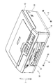
図1は、本発明の画像記録装置の一実施形態である複合機10の外観構成を示す模式斜視図である。なお、以下の説明においては、複合機10が使用可能に設置された状態(図1に示される状態)を基準として上下方向7を定義し、開口13が設けられている側を手前側(正面)として前後方向8を定義し、複合機10を手前側(正面)から見て左右方向9を定義する。
[Schematic configuration of MFP 10]
FIG. 1 is a schematic perspective view showing an external configuration of a
図1に示されるように、複合機10は、高さ(上下方向7の長さ)に対して横幅(左右方向9の長さ)及び奥行き(前後方向8の長さ)が大きい薄型の直方体形状に概ね形成されている。複合機10は、主に、下部に設けられたインクジェット記録方式のプリンタ部11と、上部に設けられたスキャナ部12とを一体的に備えた多機能装置である。複合機10は、ファクシミリ機能、プリント機能、スキャン機能、及び、コピー機能などの各種の機能を有している。プリント機能としては、記録用紙(本発明のシート部材の一例)の表面(第1面)及び裏面(第2面)の両面に画像を記録する両面画像記録機能を有している。なお、プリント機能以外の機能は任意であり、例えば、スキャン機能やコピー機能、ファクシミリ機能を有しないプリンタとして本発明の画像記録装置が実施されてもよい。
As shown in FIG. 1, the
プリンタ部11は、正面に開口13が形成されたプリンタ筐体14(本発明の装置本体の一例)を有する。プリンタ筐体14の内部にプリンタ部11の各構成要素が配置されている。開口13からプリンタ筐体14の内部側へ連続するように収容空間が区画されている。この収容空間に給紙トレイ78(本発明のトレイの一例)が装着されている。給紙トレイ78は、開口13からプリンタ筐体14の内部に対して、前後方向8(水平方向)に挿抜可能に構成されている。給紙トレイ78は、A4サイズの記録用紙(A4用紙)やハガキはなどの各種の記録用紙を保持可能に構成されている。以下、プリンタ部11の構成について詳細に説明する。なお、スキャナ部12の構成についての説明は省略する。
The
[プリンタ部11の構成]
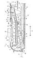
以下、図2を参照しながら、プリンタ部11の構成について詳細に説明する。図2は、プリンタ部11の内部構成を模式的に示す縦断面図である。なお、図2では、前方部分の図示が省略されている。
[Configuration of Printer Unit 11]
Hereinafter, the configuration of the
プリンタ部11は、主として、給紙トレイ78と、給紙トレイ78から記録用紙をピックアップして給紙(給送)する給送部15と、給送部15によって給紙された記録用紙にインク滴を吐出して記録用紙に画像を形成するインクジェット記録方式の画像記録部24(本発明の画像記録部の一例)と、経路切換部41と、外部に排出された記録済みの記録用紙を保持する排紙トレイ79と、プリンタ部11の動作を制御する制御部(不図示)とを備えている。これらの各構成要素がプリンタ筐体14内に設けられている。なお、画像記録部24は、インクジェット方式に限られず、電子写真方式、或いは感熱記録方式など、種々の記録方式のものが適用可能である。また、排紙トレイ79は、給紙トレイ78と一体に構成されていてもよく、或いはプリンタ筐体14のフレームなどに固定されたものであってもよい。
The
[用紙搬送路65]
プリンタ部11の内部には、給紙トレイ78の先端(後方側の端部)から上方手前側へ向かって延出され、画像記録部24を経て排紙トレイ79に至る用紙搬送路65が形成されている。記録用紙が用紙搬送路65を通ることにより、記録用紙が給紙トレイ78から排紙トレイ79まで案内される。用紙搬送路65は、給紙トレイ78の先端から画像記録部24に至る間に形成された湾曲状の湾曲路65A(本発明の湾曲搬送路の一例)と、画像記録部24から排紙トレイ79に至る間に形成された排紙路65Bとに区分される。
[Paper transport path 65]
Inside the
図2に示されるように、湾曲路65Aは、給紙トレイ78に設けられた分離傾斜板22の上端付近から画像記録部24まで延設された湾曲状の通路である。この湾曲路65Aは、プリンタ筐体14の背面側に設けられた背面カバー18(本発明の背面カバーの一例)と、この背面カバー18から前方側へ所定間隔を隔てて互いに対向するように配置された内側ガイド部材19とによって区画されている。背面カバー18及び内側ガイド部材19は、プリンタ部11の内部側を中心とする円弧形状に概ね形成されている。
As shown in FIG. 2, the
背面カバー18は、湾曲路65Aの外側ガイド面を形成するとともに、プリンタ筐体14の背面を形成している。この背面カバー18は、プリンタ筐体14の背面に対して開閉可能に設けられている。詳細には、背面カバー18は、プリンタ筐体14の下部に設けられた支軸20を中心にして、プリンタ筐体14の背面を覆う閉姿勢(図2において実線で示された姿勢)と、プリンタ筐体14から離れて湾曲路65Aを開放する開姿勢(図2において波線で示された姿勢)との間で開閉可能に支持されている。背面カバー18が上記閉姿勢のときに、その内側面によって湾曲路65Aの外側ガイド面が形成される。このような背面カバー18が設けられているため、湾曲路65Aで記録用紙が詰まった場合でも、背面カバー18を開くことによって、詰まった用紙を容易に除去できる。
The
排紙路65Bは、画像記録部24よりも前方側に設けられた上側排紙ガイド82と下側排紙ガイド83とによって区画されている。
The
下側排紙ガイド83の前方側に分岐口36が形成されている。両面画像記録の際には、排紙路65Bを搬送される記録用紙は、分岐口36の下流側でスイッチバックされ、後述する反転搬送路67へ向けて搬送される。
A
[画像記録部24]
画像記録部24は、給紙トレイ78の上側に配置されている。画像記録部24は、図2の紙面垂直方向(左右方向9)に延出されたガイドレール(不図示)に沿って往復動するように構成されている。画像記録部24の下方にプラテン42が設けられている。プラテン42は、画像記録部24によって画像記録が行われる際に、記録用紙を水平に支持するものである。画像記録部24は、主走査方向への往復移動過程において、図示しないインクカートリッジから供給されたインクをノズル39から微小なインク滴としてプラテン42上を搬送される記録用紙に吐出する。これにより、記録用紙に画像が記録される。
[Image Recording Unit 24]
The
用紙搬送路65には、記録用紙を挟持して搬送するための第1搬送ローラ60及び第2搬送ローラ62が設けられている。第1搬送ローラ60と第2搬送ローラ62の間に画像記録部24が設けられている。第1搬送ローラ60にピンチローラ61が圧接されており、第2搬送ローラ62に拍車63が圧接されている。なお、第1搬送ローラ60及び第2搬送ローラ62は、搬送用モータ(不図示)から駆動伝達機構(不図示)を介して回転駆動力が伝達されて回転される。本実施形態では、後述する第3搬送ローラ45を正回転方向又は逆回転方向へ回転させる回転駆動力も上記搬送用モータから供給される。そのため、第1搬送ローラ60及び第2搬送ローラ62への駆動伝達機構として、上記搬送用モータが正回転方向又は逆回転方向のいずれに回転されても、記録用紙を一方向(図2の右側)へ搬送させるべく、遊星ギヤなどによって第1搬送ローラ60及び第2搬送ローラ62を常に一回転方向へ回転させる機構が採用されている。なお、第1搬送ローラ60及び第2搬送ローラ62の駆動源と第3搬送ローラ45の駆動源とが別々に設けられている場合は、上記駆動伝達機構は、上記遊星ギヤを含む構成に限られない。
The
[給送部15]
給送部15は、画像記録部24と給紙トレイ78との間、更に詳細には、後述する下側ガイド部材90と給紙トレイ78との間に設けられている。給送部15は、給紙トレイ78に収容された記録用紙を湾曲路65Aへ向けて搬送するためのものであり、給紙ローラ25(本発明の給送ローラの一例)と、アーム状の部材からなる給紙アーム26と、駆動伝達機構27とを備えている。
[Feeding unit 15]
The
給紙ローラ25は、給紙トレイ78に保持されて記録用紙を一枚ずつピックアップして湾曲路65Aへ給紙するものである。給紙ローラ25は、記録用紙との接触摩擦を高めるために、シリコンやNBRなどの弾性部材で構成されている。もちろん、樹脂製の給紙ローラ25のローラ面に弾性部材がコーティングされていてもよい。この給紙ローラ25は、給紙アーム26の先端に回転自在に軸支されている。給紙ローラ25は、駆動源である給紙用モータ(不図示)の回転力が駆動伝達機構27を介して伝達されることにより、回転駆動される。なお、駆動伝達機構27は、給紙アーム26に軸支されており、給紙アーム26の延出方向に沿って概ね直線状に並ぶ複数のギヤで構成されている。
The
画像記録部24と給紙トレイ78との間に基軸28が設けられている。給紙アーム26は、その基端部が基軸28に支持されており、基軸28を回動中心として回動可能に構成されている。このため、給紙アーム26は、給紙トレイ78に対して接離可能に上下動することができる。また、給紙アーム26は、自重により又はバネ等の弾性部材による弾性力により、図2の矢印29の方向へ回動付勢されている。このため、給紙ローラ25は、例えば給紙トレイ78が給紙ローラ25の下側に配置された場合は、給紙トレイ78に保持された記録用紙の上面に圧接する。給紙アーム26は、給紙トレイ78がプリンタ筐体14に対して挿入される際に、給紙トレイ78によって、上方へ押し上げられるように構成されている。
A
[給紙トレイ78]
図2に示されるように、給紙トレイ78は、給紙部15の下方に設けられており、プリンタ筐体14の底部に配置されている。
[Paper Tray 78]
As shown in FIG. 2, the
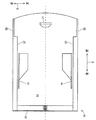
図3は、給紙トレイ78の構成を模式的に示す平面図である。図2及び図3に示されるように、給紙トレイ78は、記録用紙が載置される底板54と、底板54の左右方向9の両端部から上方に立設され、前後方向8に沿って延びる側板55,56と、底板54の後方側の端部に立設され、左右方向9に沿って延びる分離傾斜板22とを備えている。給紙トレイ78は、上面が開放された概ね矩形箱状に構成されている。分離傾斜板22は、記録用紙を円滑に給紙可能なように後方側へ傾倒している。上述したとおり、記録用紙は、給紙トレイ78の後方側の端部から、当該端部の後方且つ上方の湾曲路65Aへ給送される。
FIG. 3 is a plan view schematically showing the configuration of the
また、給紙トレイ78の左右方向両端部それぞれには一対の支持部57(本発明の第1支持部及び第2支持部の一例)が設けられている。この支持部57は、側板55及び側板56それぞれと一体に構成されている。一方の支持部57は、側板55の上端から給紙トレイ78の幅方向中央側へ伸びる板部材であり、他方の支持部57は、側板56の上端から給紙トレイ78の幅方向中央側へ伸びる板部材である。これらの2つの支持部57は、後述する突起101及び突起102と共に、本発明の第1支持機構を構成する。
In addition, a pair of support portions 57 (an example of the first support portion and the second support portion of the present invention) are provided at both left and right ends of the
給紙トレイ78の底板54には、前後方向8に沿って延びる一対のサイドガイド75が設けられている。給紙トレイ78には、サイドガイド75を連動させる周知の機構が設けられている。したがって、例えば、一方のサイドガイド75が左右方向9のいずれか一方(右向き)へスライドされると、他方のサイドガイド75がこのスライド動作に連動して、逆向き(左向き)へスライドされる。このため、底板54に載置された記録用紙の幅が一対のサイドガイド75の離間距離よりも狭い場合は、サイドガイド75を記録用紙の両端に向けてスライドさせることで、記録用紙の幅方向(左右方向9)の中央位置が給紙トレイ78の幅方向の中央に略一致する。このようなサイドガイド75が設けられているため、給紙トレイ78の幅サイズよりも小さいサイズの記録用紙(例えばハガキやL版写真サイズの光沢紙など)が載置されても、その記録用紙を給紙トレイ78の中央に位置決めすることができる。なお、サイドガイドは一つであってもよい。この場合、サイドガイドと側板55,56のいずれかとの間で記録用紙を位置決めすることができる。
The
また、底板54には、前後方向8へスライド可能に支持されたリアガイド77が設けられている。そのため、給紙トレイ78に載置された記録用紙の前方側の端部へ向けてリアガイド77をスライドさせて記録用紙を後方へ押し付けることで、記録用紙を給紙トレイ78の後方側へ詰め寄せることができる。
The
[経路切換部41]
図2に示されるように、経路切換部41は、用紙搬送路65における分岐口36付近に配置されている。経路切換部41は、第3搬送ローラ45と、拍車46と、フラップ49で構成されている。
[Route switching unit 41]
As shown in FIG. 2, the
第3搬送ローラ45は、下側排紙ガイド83よりも下流側に設けられている。第3搬送ローラ45と下側排紙ガイド83との間に分岐口36が形成されている。第3搬送ローラ45は、プリンタ筐体14のフレームなどに回転可能に支持されている。拍車46は、第3搬送ローラ45の上方に配置されており、自重若しくはバネなどによって第3搬送ローラ45のローラ面に圧接されている。拍車46は、上側排紙ガイド82の下流側端部に回転可能の支持されている。第3搬送ローラ45は、搬送用モータから正逆回転方向の駆動力が伝達されて、正回転方向又は逆回転方向に回転駆動される。例えば、片面記録が行われる場合は、第3搬送ローラ45は正回転方向へ回転される。これにより、記録用紙は第3搬送ローラ45及び拍車46に挟持されて前方の排紙トレイ79へ排出される。一方、両面記録が行われる場合は、第3搬送ローラ45及び拍車46が記録用紙の後端部を挟持した状態で、第3搬送ローラ45の回転方向が正回転方向から逆回転方向へ切り換えられる。
The
プリンタ筐体14のフレームなどに、図2の紙面垂直方向(左右方向9)へ延びる支軸87が設けられている。フラップ49は、支軸87から概ね下流側へ延出されている。フラップ49は、支軸87に回動可能に軸支されている。フラップ49には、その延出方向に隔てられた拍車47及び拍車48が軸支されている。フラップ49は、姿勢変化可能に構成されており、下側排紙ガイド83よりも上方に位置する排出姿勢(図2に破線で示される姿勢)と、延出端部49Aが分岐口36よりも下方へ進入する反転姿勢(図2に実線で示される姿勢)との間で回動する。このようなフラップ49が設けられているため、記録用紙の後端がフラップ49を通過してプラップ49が反転姿勢となると、記録用紙の後端が分岐口36の下方へ向けられる。そして、第3搬送ローラが逆回転すると、記録用紙が反転搬送路67へ向けてスイッチバック搬送される。
A
[反転搬送路67]
プリンタ部11の内部には、反転搬送路67が形成されている。反転搬送路67は、排紙路65Bの分岐口36から分岐して、画像記録部24と給紙部15との間を通って後方へ延出され、湾曲路65Aの途中にある合流部37に合流している。反転搬送路67は、前方側の傾斜路67Aと、後方側の直線路67Bとに区分される。経路切換部41でスイッチバック搬送された記録用紙が反転搬送路67を通ることにより、記録用紙が再び湾曲路65Aに戻される。この反転搬送路67は、プリンタ筐体14に固定された上側固定ガイド板43と、画像記録部24及び給紙部15の間に設けられた下側ガイド部材90(本発明のガイド部材の一例)とによって形成されている。
[Reverse conveying path 67]
A
[下側ガイド部材90]
図2に示されるように、下側ガイド部材90は、大別すると、回動軸93(本発明の回動軸の一例)と、回動軸よりも前方側に配置された前方ガイド板91(本発明の第2ガイド板の一例)と、回動軸93よりも後方側に配置された後方ガイド板92(本発明の第1ガイド板の一例)とにより構成されている。
[Lower guide member 90]
As shown in FIG. 2, the
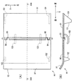
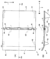
図4は、下側ガイド部材90の構成を示す模式図であって、(A)には下側ガイド部材90の平面図が示されており、(B)には(A)における切断線IVB−IVBの断面図が示されている。なお、図4では、下側ガイド部材90が水平にされた状態が示されている。図4に示されるように、回動軸93は左右方向の延びる丸棒状の部材からなる。この回動軸93は、プリンタ筐体15に固定されている。
4A and 4B are schematic views showing the configuration of the
図4に示されるように、前方ガイド板91及び後方ガイド板92は、給紙トレイ78の幅と概ね同じ幅を有する平板状の部材からなる。前方ガイド板91の後方端における左右方向両端それぞれに軸受け94が設けられている。この軸受け94に設けられた軸孔(不図示)に回動軸93が挿通されている。これにより、前方ガイド板91は、その前方端を回動自由端として回動軸93を中心に回動可能となる。また、後方ガイド板92の前方端おける左右方向両端それぞれに軸受け95が設けられている。この軸受け95に設けられた軸孔(不図示)に回動軸93が挿通されている。これにより、後方ガイド板92は、その後方端を回動自由端として回動軸93を中心に回動可能となる。つまり、前方ガイド板91及び後方ガイド板92は、共通の回動軸93によって回動自在に支持されている。
As shown in FIG. 4, the
図4に示されるように、後方ガイド板92は、給紙ローラ25の上側に配置されている。したがって、回動軸93を中心に後方ガイド板92が下方へ回動すると、後方ガイド板92の下面と給紙ローラ25のローラ面とが接触する。
As shown in FIG. 4, the
また、前方ガイド板91及び後方ガイド板92は、いずれも同じ厚みに形成されており、また、同材料で形成されている。しかし、後方ガイド板92は、前方ガイド板91に比べて前後方向8に長く形成されている。そのため、後方ガイド板92は前方ガイド板よりも重い。したがって、上述の如く回動軸93によって回動自在な状態においては、後方ガイド板92が下方へ回動しようとするモーメントは、前方ガイド板91が下方へ回動しようとするモーメントよりも大きい。このようなモーメントの差は、後方ガイド板92と前方ガイド板91との間に重量差を設けることにより、実現している。このような重量差を設けることが、前方ガイド板91に作用する下方へのモーメントよりも後方ガイド板92に作用する下方へのモーメントが大きくなるように後方ガイド板92に下方への付勢力を付与する付与手段の一例である。なお、本発明の付勢手段を上記重量差とは異なる手段で実現してもかまわない。例えば、付勢手段の他の例として、後方ガイド板92を下方へ付勢するねじりコイルバネを回動軸93に取り付けてもよい。
Moreover, both the
図4に示されるように、前方ガイド板91の下面に2つの突起101(本発明の第2係合部の一例)が設けられている。突起101は、前方ガイド板91の前方端における左右方向両端部それぞれに設けられている。突起101は、前方ガイド板91の下面から下方へ突出している。突起101は、給紙トレイ78がプリンタ筐体14に装着された状態で、上述した支持部57に当接して支持される。これにより、図2に示されるように、分岐口36から回動軸93までに至る傾斜路67Aが前方ガイド板91によって形成される。なお、突起101の前方側には、前方ガイド板91の下面に対して傾斜する傾斜面104が形成されている。この傾斜面104は、プリンタ筐体14に対して給紙トレイ78の挿入動作を円滑にするためのものである。
As shown in FIG. 4, two protrusions 101 (an example of the second engagement portion of the present invention) are provided on the lower surface of the
また、後方ガイド板92の下面に2つの突起102(本発明の第1係合部の一例)が設けられている。突起102は、後方ガイド板92の後方端における左右方向両端部それぞれに設けられている。突起102は、後方ガイド板92の下面から下方へ突出している。突起102は、給紙トレイ78がプリンタ筐体14に装着された状態で、上述した支持部57に当接して支持される。これにより、図2に示されるように、回動軸93から合流部37までに至る直線路67Bが後方ガイド板92によって形成される。つまり、給紙トレイ78がプリンタ筐体14に装着された状態にあるときに、下側ガイド部材90によって、記録用紙を湾曲路65Aへ案内可能な反転搬送路67が形成される。このように反転搬送路67が形成される下側ガイド部材90の姿勢が、本発明の第1姿勢に相当する。
In addition, two protrusions 102 (an example of the first engaging portion of the present invention) are provided on the lower surface of the
後方ガイド板92の後端には、後方斜め上方へ向けて傾倒する傾斜部97が形成されている。この傾斜部97は、合流部37において湾曲路65Aに接続している。このため、直線路67Bから後方へ水平に搬送された記録用紙は、傾斜部97によってその方向が上向きに変えられる。したがって、直線路67Bから湾曲路65Aへ向かう記録用紙が円滑に搬送される。
An
前方ガイド板91には、湾曲状に形成された2つの規制片105(本発明の第2支持機構、突出片の一例)が設けられている。これらの規制片105は、前方ガイド板91の後方端における左右方向中央部に所定間隔を隔てて設けられている。規制片105は、前方ガイド板91の下面から下方へ突出しており、回動軸93を中心とする円弧状に概ね形成されている。この規制片105は、前方ガイド板91及び後方ガイド板92が下方へ回動したときに、それぞれのガイド板91,92を後述する角度θ(図5(D)参照)よりも近づけないように規制するものである。
The
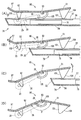
[下側ガイド部材90の動作]
以下、図5を参照しながら、下側ガイド部材90の動作について説明する。図5は、下側ガイド部材90の動作を説明する模式断面図である。図5(A)には給紙トレイ78の装着状態が示されており、(B)には給紙トレイ78によって給紙アーム26が支持された状態が示されており、(C)には給紙トレイ78によって前方ガイド板91のみが持ち上げられた状態が示されており、(D)には、給紙トレイ78が未装着となって後方ガイド板92及び前方ガイド板91双方の支持が解除された状態が示されている。なお、図5では、説明の便宜上、下側ガイド部材90及び給紙トレイ78以外の構成の図示を省略している。また、給送部15が波線で示されている。
[Operation of Lower Guide Member 90]
Hereinafter, the operation of the
上述したように、本実施形態では、図5(A)に示されるように、給紙トレイ78がプリンタ筐体14に装着された状態にあるときに、前方ガイド板91によって傾斜路67Aが形成され、後方ガイド板92によって直線路67Bが形成される。この状態から給紙トレイ78が抜き出されると、まず最初に、突起102が支持部57によって支持されなくなる(図5(B)参照)。なお、図5(B)に示される状態では、給紙トレイ78が給紙アーム26を支持している。この状態で、給紙ローラ25が後方ガイド板92の下面に当接することにより、給紙ローラ25が後方ガイド板92を上方へ持ち上げるように支持している。
As described above, in this embodiment, as shown in FIG. 5A, when the
そして、給紙トレイ78が更に抜き出されると、図5(C)に示されるように、給紙アーム26の支持がなくなり、給紙ローラ25がプリンタ筐体14の底面へ向けて回動し、その底面に衝突して静止する。また、後方ガイド板92も下方へ回動し、その下面が給紙ローラ25に当接することにより静止する。なお、上述したように、給紙ローラ25は弾性部材で構成されているため、給紙ローラ25が上記底面に衝突したとき、及び、後方ガイド板92の下面が給紙ローラ25に当接したときに生じる衝突音が抑制される。
When the
更に給紙トレイ78が抜き出されて、図5(D)に示されるように、給紙トレイ78が下側ガイド部材90から離れると、突起101が支持部57によって支持されなくなる。これにより、前方ガイド板91が下方へ回動する。前方ガイド板91が下方へ回動して、前方ガイド板91と後方ガイド板92とのなす角が角度θ(本発明の所定角度に相当)となると、規制片105の先端が後方ガイド板92の下面に当接して、前方ガイド板91及び後方ガイド板92がそれ以上近づかないように規制する。なお、上述したように、前方ガイド板91よりも後方ガイド板92の方が下方へのモーメントが大きいので、規制片105の当接によって後方ガイド板92が持ち上げられることはない。
Further, when the
本実施形態では、上記角度θは、給紙トレイ78がプリンタ筐体14から抜き出された状態(未装着状態)で、前方ガイド板91の前方端がプリンタ筐体14の底面から離間した位置で静止可能な角度に設定されている。そのため、給紙トレイ78が抜き出されても、前方ガイド板91がプリンタ筐体の底面に衝突しないので、衝突による前方ガイド板91の損壊や防止され、衝突音の発生が防止される。
In the present embodiment, the angle θ is a position where the front end of the
なお、給紙トレイ78がプリンタ筐体14に挿入されると、まず、給紙トレイ78の分離傾斜板22が突起101の傾斜面104に当接する。分離傾斜板22は、傾斜面104に当接しつつ滑るようにして後方へ移動し、その移動に伴って前方ガイド板91が上方へ持ち上げられてる。突起101が支持部57に乗り上げられて、この支持部57に支持される(図5(C)参照)。このとき、前方ガイド板91によって傾斜路65Aが形成される。そして、更に給紙トレイ78が奥まで挿入されると、分離傾斜板22が給紙アーム26及び給紙ローラ25を持ち上げ(図5(B)参照)、さらに、給紙ローラ25によって後方ガイド板92が持ち上げられる。そして、突起102が支持部57に乗り上げられて、この支持部57に支持される(図5(A)参照)。このとき、後方ガイド板92によって直線路65Bが形成される。
When the
[実施形態の効果]
このように構成されているため、給紙トレイ78がプリンタ筐体14から抜き出されることにより、後方ガイド板92及び前方ガイド板91が下方へ回動する。回動軸93を中心にして後方ガイド板92が下方へ回動すると、反転搬送路67の直線路67Bが高さ方向に拡げられる。このため、反転搬送路67で記録用紙が詰まった場合でも、背面カバー18を開ければ、詰まった記録用紙に容易にアクセスすることができるので、記録用紙の除去作業が容易となる。また、回動軸93を中心にして前方ガイド板91が下方へ回動すると、反転搬送路67の傾斜路67Aが高さ方向に拡げられる。このため、反転搬送路67で記録用紙が詰まった場合でも、プリンタ筐体14の開口13から詰まった記録用紙に容易にアクセスすることができるので、記録用紙の除去作業が容易となる。
[Effect of the embodiment]
Since it is configured in this manner, the
なお、上述の実施形態では、前方ガイド板91に突起101を設け、後方ガイド板92に突起102を設けることとしたが、前方ガイド板91及び後方ガイド板92には突起101,突起102を設けずに、これらの突起101,102と同様の突起を給紙トレイ78の側板55,56に設けた構成であっても、本発明は適用可能である。
In the above-described embodiment, the
[実施形態の変形例]
図6は、本発明の変形例に係る下側ガイド部材90の構成を示す模式図であって、(A)には下側ガイド部材90の平面図が示されており、(B)には(A)における切断線VIB−VIBの断面図が示されている。図6に示されるように、反転搬送路67に案内された記録用紙を湾曲路65Aへ搬送するために、反転搬送路67に、搬送ローラ108及びこれに圧接されて従動するピンチローラ109(本発明の搬送ローラ対の一例)を設けられている。この変形例では、搬送ローラ108が回動軸93によって支持されており、ピンチローラ109は搬送ローラ108の上側で図示しない支軸で回転可能に支持されている。このばあい、搬送ローラ108の支軸として回動軸93を兼用できるので、装置をよりコンパクトにすることができる。また、搬送ローラ108が位置する部分が支点となって前方ガイド板91及び後方ガイド板92それぞれが下方へ下がるため、搬送ローラ108及びピンチローラ108によって挟持された状態で記録用紙が詰まった場合でも、挟持されている部分に装置の正面及び背面の両方からアクセスできるので、記録用紙を取り除くことが容易である。この変形例において、搬送ローラ108に代えて、ピンチローラ109を回動軸に軸支させてもかまわない。
[Modification of Embodiment]
FIG. 6 is a schematic view showing a configuration of a
10・・・複合機
11・・・プリンタ部
14・・・プリンタ筐体
15・・・給送部
18・・・背面カバー
24・・・画像記録部
25・・・給紙ローラ
65・・・用紙搬送路
65A・・・湾曲路
67・・・反転搬送路
90・・・下側ガイド部材
91・・・前方ガイド板
92・・・後方ガイド板
93・・・回動軸
101,102・・・突起
105・・・規制片
108・・・搬送ローラ
109・・・ピンチローラ
DESCRIPTION OF
Claims (6)
上記トレイの上側に設けられた画像記録部と、
上記装置本体の背面に開閉可能に設けられ、閉じられた状態で上記トレイから上記画像記録部に至る湾曲状の湾曲搬送路を形成し、開けられた状態で上記湾曲搬送路を開放する背面カバーと、
上記トレイと上記画像記録部との間に設けられた第1ガイド板及び第2ガイド板を有し、上記画像記録部を通過したシート部材を上記第2ガイド板及び上記第1ガイド板を順次経て上記湾曲搬送路へ案内するガイド部材と、
正面側の端部を回動自由端として上記第2ガイド板を回動自在に支持するとともに、背面側の端部を回動自由端として上記第1ガイド板を回動自在に支持する回動軸と、
上記第2ガイド板に作用する下方へのモーメントよりも上記第1ガイド板に作用する下方へのモーメントが大きくなるように上記第1ガイド板に下方への付勢力を付与する付与手段と、
上記トレイが上記装置本体に挿入されたことに応じて、上記湾曲搬送路へのシート部材の案内が可能な第1姿勢となるように上記モーメントに抗して上記ガイド部材を支持する第1支持機構と、
上記トレイが上記装置本体から脱抜されたときに上記第1支持機構による支持が解除されて下方へ回動した上記各ガイド板が所定角度をなす第2姿勢となるように上記ガイド部材を支持する第2支持機構と、
を具備する画像記録装置。 A tray provided so as to be insertable / removable with respect to the apparatus main body from the front of the apparatus main body, and holding a sheet member on which an image is recorded;
An image recording unit provided on the upper side of the tray;
A back cover that can be opened and closed on the back surface of the apparatus main body, forms a curved curved conveyance path from the tray to the image recording unit in a closed state, and opens the curved conveyance path in an opened state. When,
A first guide plate and a second guide plate provided between the tray and the image recording unit, and sheet members that have passed through the image recording unit are sequentially placed on the second guide plate and the first guide plate. A guide member for guiding to the curved conveyance path through,
The second guide plate is pivotally supported with the front end serving as a pivot free end, and the first guide plate is pivotably supported with the rear end serving as a pivot free end. The axis,
Applying means for applying a downward biasing force to the first guide plate such that a downward moment acting on the first guide plate is greater than a downward moment acting on the second guide plate;
A first support that supports the guide member against the moment so as to be in a first posture capable of guiding the sheet member to the curved conveyance path in response to the tray being inserted into the apparatus main body. Mechanism,
When the tray is removed from the apparatus main body, the support by the first support mechanism is released, and the guide plates that are rotated downward support the guide member so as to be in a second posture at a predetermined angle. A second support mechanism that
An image recording apparatus comprising:
上記搬送ローラ対のいずれか一方のローラが上記回動軸によって回動可能に支持されている請求項1に記載の画像記録装置。 It is composed of two rollers pressed in the vertical direction, further comprising a pair of conveyance rollers that conveys the sheet member guided by the guide member toward the curved conveyance path,
The image recording apparatus according to claim 1, wherein one of the conveying roller pairs is rotatably supported by the rotation shaft.
上記第1ガイド板は、上記トレイが上記装置本体から脱抜されたときに下方へ回動し、上記給送ローラのローラ面に当接することによって静止する請求項1から3のいずれかに記載の画像記録装置。 An elastic member is provided between the tray and the guide member, the roller surface is provided with an elastic member, and further includes a feeding roller for feeding the sheet member held on the tray to the curved conveyance path,
4. The first guide plate according to claim 1, wherein the first guide plate rotates downward when the tray is removed from the apparatus main body, and stops by contacting the roller surface of the feeding roller. Image recording device.
上記第1ガイド板の下面に設けられた第1係合部と、上記トレイが上記装置本体に装着されたときに上記第1係合部と係合して上記第1ガイド板を下側から持ち上げるように支持する第1支持部と、
上記第2ガイド板の下面に設けられた第2係合部と、上記トレイが上記装置本体に装着されたときに上記第2係合部と係合して上記第2ガイド板を下側から持ち上げるように支持する第2支持部と、により構成されている請求項1から4のいずれかに記載の画像記録装置。 The first support mechanism includes:
A first engaging portion provided on the lower surface of the first guide plate, and when the tray is mounted on the apparatus main body, the first engaging portion is engaged with the first engaging portion from below. A first support for supporting the lift;
A second engagement portion provided on the lower surface of the second guide plate, and when the tray is mounted on the apparatus main body, engages with the second engagement portion to bring the second guide plate from the lower side. The image recording apparatus according to claim 1, further comprising a second support part that supports the lifter so as to lift it.
上記突出片は、その先端が他方のガイド板に当接することにより各ガイド板がなす角度を上記所定角度に維持する請求項1から5のいずれかに記載の画像記録装置。
The second support mechanism has a projecting piece projecting from the vicinity of the rotation shaft in one of the guide plates.
The image recording apparatus according to claim 1, wherein the protruding piece maintains an angle formed by each guide plate at the predetermined angle by contacting a tip of the protruding piece with the other guide plate.
Priority Applications (1)
| Application Number | Priority Date | Filing Date | Title |
|---|---|---|---|
| JP2009299264A JP5263148B2 (en) | 2009-12-29 | 2009-12-29 | Image recording device |
Applications Claiming Priority (1)
| Application Number | Priority Date | Filing Date | Title |
|---|---|---|---|
| JP2009299264A JP5263148B2 (en) | 2009-12-29 | 2009-12-29 | Image recording device |
Publications (2)
| Publication Number | Publication Date |
|---|---|
| JP2011136829A true JP2011136829A (en) | 2011-07-14 |
| JP5263148B2 JP5263148B2 (en) | 2013-08-14 |
Family
ID=44348661
Family Applications (1)
| Application Number | Title | Priority Date | Filing Date |
|---|---|---|---|
| JP2009299264A Active JP5263148B2 (en) | 2009-12-29 | 2009-12-29 | Image recording device |
Country Status (1)
| Country | Link |
|---|---|
| JP (1) | JP5263148B2 (en) |
Cited By (6)
| Publication number | Priority date | Publication date | Assignee | Title |
|---|---|---|---|---|
| JP2013032210A (en) * | 2011-08-02 | 2013-02-14 | Brother Industries Ltd | Image recording device |
| CN103030018A (en) * | 2011-09-30 | 2013-04-10 | 兄弟工业株式会社 | Image recording apparatus |
| JP2013116783A (en) * | 2011-12-02 | 2013-06-13 | Brother Industries Ltd | Image recording apparatus |
| JP2014118240A (en) * | 2012-12-14 | 2014-06-30 | Brother Ind Ltd | Image recording device |
| US10059546B2 (en) | 2015-03-03 | 2018-08-28 | Canon Kabushiki Kaisha | Sheet conveying apparatus and image forming apparatus |
| US11438481B2 (en) | 2019-03-28 | 2022-09-06 | Brother Kogyo Kabushiki Kaisha | Image reading apparatus and image forming apparatus comprising a first wall, a second wall, a harness interposed between the first wall and second wall, a third wall, the harness not interposed between the first wall and third wall, and a plurality of fourth walls spaced apart from each other extending in an orthogonal direction orthogonal to the first direction in which the first wall and the third wall extend and protruding upward from the bottom of the harness accommodating portion |
Citations (2)
| Publication number | Priority date | Publication date | Assignee | Title |
|---|---|---|---|---|
| JP2007261820A (en) * | 2007-07-20 | 2007-10-11 | Kyocera Mita Corp | Paper conveying mechanism and perfecting machine using it |
| JP2007334197A (en) * | 2006-06-19 | 2007-12-27 | Kyocera Mita Corp | Image forming apparatus |
-
2009
- 2009-12-29 JP JP2009299264A patent/JP5263148B2/en active Active
Patent Citations (2)
| Publication number | Priority date | Publication date | Assignee | Title |
|---|---|---|---|---|
| JP2007334197A (en) * | 2006-06-19 | 2007-12-27 | Kyocera Mita Corp | Image forming apparatus |
| JP2007261820A (en) * | 2007-07-20 | 2007-10-11 | Kyocera Mita Corp | Paper conveying mechanism and perfecting machine using it |
Cited By (8)
| Publication number | Priority date | Publication date | Assignee | Title |
|---|---|---|---|---|
| JP2013032210A (en) * | 2011-08-02 | 2013-02-14 | Brother Industries Ltd | Image recording device |
| CN103030018A (en) * | 2011-09-30 | 2013-04-10 | 兄弟工业株式会社 | Image recording apparatus |
| CN103030018B (en) * | 2011-09-30 | 2015-07-29 | 兄弟工业株式会社 | Image recorder |
| JP2013116783A (en) * | 2011-12-02 | 2013-06-13 | Brother Industries Ltd | Image recording apparatus |
| US8746687B2 (en) | 2011-12-02 | 2014-06-10 | Brother Kogyo Kabushiki Kaisha | Image forming apparatus capable of duplex printing |
| JP2014118240A (en) * | 2012-12-14 | 2014-06-30 | Brother Ind Ltd | Image recording device |
| US10059546B2 (en) | 2015-03-03 | 2018-08-28 | Canon Kabushiki Kaisha | Sheet conveying apparatus and image forming apparatus |
| US11438481B2 (en) | 2019-03-28 | 2022-09-06 | Brother Kogyo Kabushiki Kaisha | Image reading apparatus and image forming apparatus comprising a first wall, a second wall, a harness interposed between the first wall and second wall, a third wall, the harness not interposed between the first wall and third wall, and a plurality of fourth walls spaced apart from each other extending in an orthogonal direction orthogonal to the first direction in which the first wall and the third wall extend and protruding upward from the bottom of the harness accommodating portion |
Also Published As
| Publication number | Publication date |
|---|---|
| JP5263148B2 (en) | 2013-08-14 |
Similar Documents
| Publication | Publication Date | Title |
|---|---|---|
| JP2011157155A (en) | Image recording device | |
| JP4508244B2 (en) | Sheet conveying apparatus and image recording apparatus provided with the same | |
| JP4609579B2 (en) | Image recording device | |
| JP4645718B2 (en) | Image recording device | |
| JP2009023831A (en) | Image recording device | |
| JP6136821B2 (en) | Sheet conveying apparatus and image recording apparatus | |
| JP5263148B2 (en) | Image recording device | |
| JP7513174B2 (en) | Image Recording Device | |
| JP2012000872A (en) | Image recording apparatus | |
| JP5482648B2 (en) | Image recording device | |
| JP2013075759A (en) | Image recording apparatus | |
| JP2009007139A (en) | Image recording device | |
| JP5590059B2 (en) | Image recording device | |
| JP4998457B2 (en) | Image recording device | |
| JP2010235311A (en) | Sheet storage device and image recording apparatus provided with the same | |
| JP6693535B2 (en) | Sheet conveying device and image recording device | |
| JP5029630B2 (en) | Sheet conveying apparatus and image recording apparatus | |
| JP5835397B2 (en) | Image recording device | |
| JP6172584B2 (en) | Image recording device | |
| JP6323596B2 (en) | Sheet conveying apparatus and image recording apparatus | |
| JP2010173841A (en) | Sheet carrying device and image recorder | |
| JP2010042925A (en) | Sheet storage device and image recording device | |
| JP6658807B2 (en) | Image recording device | |
| JP2004203509A (en) | Sheet feeding device and image reading / recording device provided with the same | |
| JP7192316B2 (en) | Sheet conveying device and image recording device |
Legal Events
| Date | Code | Title | Description |
|---|---|---|---|
| A621 | Written request for application examination |
Free format text: JAPANESE INTERMEDIATE CODE: A621 Effective date: 20120130 |
|
| A977 | Report on retrieval |
Free format text: JAPANESE INTERMEDIATE CODE: A971007 Effective date: 20130326 |
|
| TRDD | Decision of grant or rejection written | ||
| A01 | Written decision to grant a patent or to grant a registration (utility model) |
Free format text: JAPANESE INTERMEDIATE CODE: A01 Effective date: 20130402 |
|
| A61 | First payment of annual fees (during grant procedure) |
Free format text: JAPANESE INTERMEDIATE CODE: A61 Effective date: 20130415 |
|
| R150 | Certificate of patent or registration of utility model |
Ref document number: 5263148 Country of ref document: JP Free format text: JAPANESE INTERMEDIATE CODE: R150 Free format text: JAPANESE INTERMEDIATE CODE: R150 |