JP2011106966A - Stress sensor, method of detecting stress, stress detection system, and method of constructing stress detector - Google Patents
Stress sensor, method of detecting stress, stress detection system, and method of constructing stress detector Download PDFInfo
- Publication number
- JP2011106966A JP2011106966A JP2009262361A JP2009262361A JP2011106966A JP 2011106966 A JP2011106966 A JP 2011106966A JP 2009262361 A JP2009262361 A JP 2009262361A JP 2009262361 A JP2009262361 A JP 2009262361A JP 2011106966 A JP2011106966 A JP 2011106966A
- Authority
- JP
- Japan
- Prior art keywords
- stress
- optical fiber
- visible light
- detected
- sensor
- Prior art date
- Legal status (The legal status is an assumption and is not a legal conclusion. Google has not performed a legal analysis and makes no representation as to the accuracy of the status listed.)
- Pending
Links
- 238000001514 detection method Methods 0.000 title claims abstract description 52
- 238000000034 method Methods 0.000 title claims abstract description 14
- 239000013307 optical fiber Substances 0.000 claims abstract description 203
- 239000000758 substrate Substances 0.000 claims description 18
- 239000000853 adhesive Substances 0.000 claims description 14
- 238000010276 construction Methods 0.000 claims description 12
- 230000001070 adhesive effect Effects 0.000 claims description 11
- 238000009826 distribution Methods 0.000 claims description 7
- 238000012544 monitoring process Methods 0.000 claims description 3
- 230000001737 promoting effect Effects 0.000 claims description 2
- 230000000007 visual effect Effects 0.000 abstract description 6
- 230000003287 optical effect Effects 0.000 description 24
- 239000010410 layer Substances 0.000 description 8
- 239000012790 adhesive layer Substances 0.000 description 6
- 238000010586 diagram Methods 0.000 description 5
- 238000009434 installation Methods 0.000 description 5
- 239000011253 protective coating Substances 0.000 description 5
- 238000005452 bending Methods 0.000 description 4
- 239000011248 coating agent Substances 0.000 description 4
- 238000000576 coating method Methods 0.000 description 4
- 239000000835 fiber Substances 0.000 description 4
- 238000012423 maintenance Methods 0.000 description 3
- KRHYYFGTRYWZRS-UHFFFAOYSA-N Fluorane Chemical compound F KRHYYFGTRYWZRS-UHFFFAOYSA-N 0.000 description 2
- 230000015572 biosynthetic process Effects 0.000 description 2
- 230000006866 deterioration Effects 0.000 description 2
- 238000005498 polishing Methods 0.000 description 2
- 229920005989 resin Polymers 0.000 description 2
- 239000011347 resin Substances 0.000 description 2
- 230000035945 sensitivity Effects 0.000 description 2
- 238000011179 visual inspection Methods 0.000 description 2
- 239000004593 Epoxy Substances 0.000 description 1
- 239000004962 Polyamide-imide Substances 0.000 description 1
- 239000011247 coating layer Substances 0.000 description 1
- 238000012790 confirmation Methods 0.000 description 1
- 238000005336 cracking Methods 0.000 description 1
- 238000005520 cutting process Methods 0.000 description 1
- 238000002845 discoloration Methods 0.000 description 1
- 229920006332 epoxy adhesive Polymers 0.000 description 1
- 230000003628 erosive effect Effects 0.000 description 1
- 238000005530 etching Methods 0.000 description 1
- 238000007689 inspection Methods 0.000 description 1
- 238000004519 manufacturing process Methods 0.000 description 1
- 229920002312 polyamide-imide Polymers 0.000 description 1
- 230000001681 protective effect Effects 0.000 description 1
- 239000000126 substance Substances 0.000 description 1
- XLYOFNOQVPJJNP-UHFFFAOYSA-N water Substances O XLYOFNOQVPJJNP-UHFFFAOYSA-N 0.000 description 1
Images

Landscapes
- Optical Transform (AREA)
- Length Measuring Devices By Optical Means (AREA)
Abstract
Description
本発明は、光ファイバを用いて披検知部に生ずる応力を検知する応力センサと応力検知システム、この応力センサを用いて披検知部に生ずる応力を検知する応力検知方法、披検知部に生ずる応力を検知するための光ファイバを被検出部に貼着する応力検出部の施工方法に関するものである。 The present invention relates to a stress sensor and a stress detection system for detecting a stress generated in the detection unit using an optical fiber, a stress detection method for detecting a stress generated in the detection unit using the stress sensor, and a stress generated in the detection unit. It is related with the construction method of the stress detection part which sticks the optical fiber for detecting this to a to-be-detected part.
構造物における日常的な維持管理では、外観を目視することによる目視点検が広く実施されている。目視点検は、構造物の損傷や劣化の早期発見、及び劣化の進み具合の確認等を目的として実施されているが、構造物にひび割れ、浮き、漏水、沈下、変形、変色等の損傷が発生した直後ではなく、しばらく時間が経過した後に点検されることが多いため、本質的な意味での維持管理とは言い難い。そのため、日常的な維持管理の点検方法としては、ひずみゲージ、光ファイバ、各種センサを用いる方法が知られている。 In daily maintenance management of structures, visual inspection by visually observing the appearance is widely performed. Visual inspection is performed for the purpose of early detection of damage and deterioration of the structure and confirmation of the progress of deterioration, but damage such as cracking, floating, water leakage, subsidence, deformation, and discoloration occurs in the structure. Since it is often inspected after a certain amount of time, not immediately after it has been done, it is difficult to say that it is an essential maintenance. Therefore, a method using a strain gauge, an optical fiber, and various sensors is known as a daily maintenance management inspection method.
従来、ひび割れ等の原因となる応力が構造物に発生した場合に、この応力を検知するためのセンサが知られている(例えば、特許文献1参照)。特許文献1に開示されたセンサには光ファイバが備えられており、このセンサが構造物の被検出部に固設されている。この光ファイバは、被検出部への応力により生じたひずみが所定値を超えたときに破断するように形成されている。又、この光ファイバには、可視光が導入されている。そのため、特許文献1のセンサでは、光ファイバに導入された可視光が破断した箇所で漏れて発光するため、ひび割れなどによる構造物の損傷を目視で容易に検知することが可能となる。
2. Description of the Related Art Conventionally, a sensor for detecting a stress that causes a crack or the like in a structure is known (for example, see Patent Document 1). The sensor disclosed in
しかしながら、特許文献1に開示されたセンサでは、光ファイバが破断する前の段階で、ひび割れの原因となる応力の発生を事前に検知することについては考慮されていない。このため、ひび割れの原因となる応力の発生をより早期に容易に検知し得るセンサが望まれていた。
However, in the sensor disclosed in
本発明は、ひび割れの原因となる応力の生じている場所を発光により容易に視覚的に検知することのできる応力センサ、応力検知方法、応力検知システム及び応力検出部の施工方法を提供することを目的とする。 It is an object of the present invention to provide a stress sensor, a stress detection method, a stress detection system, and a method for constructing a stress detection unit that can easily visually detect a place where a stress causing a crack is generated by light emission. Objective.
本発明の応力センサは、被検知部に生じる応力が伝達されるように該被検知部に少なくとも一部が装着されると共に可視光が導入される光ファイバを備え、該光ファイバの前記被検知部に装着される部分の表面にマイクロベンディング現象による光の漏出を促進する凹凸部を設けたことを特徴とする。 The stress sensor of the present invention includes an optical fiber that is at least partially attached to the detected portion and in which visible light is introduced so that the stress generated in the detected portion is transmitted. An uneven portion for promoting light leakage due to a microbending phenomenon is provided on a surface of a portion to be attached to the portion.
本発明によれば、被検知部に生じた応力によって光ファイバがマイクロベンディング現象を生ずる程に屈曲された場合に、可視光が光ファイバの屈曲部から漏れ出る。可視光の漏出は凹凸部により促進されるため、光ファイバの屈曲に対する可視光の漏出量が多くなり、該可視光の漏出を容易に視覚的に認識できる。このため、ひび割れ発生前又は光ファイバの破断前に被検出部に生じている応力を視覚的な認識によって容易に検知することができる。ひいては、被検知部のひび割れを防止するための対策等を早期に施すことも可能となる。なお、ここで、「視覚的な認識」は、人間の目による直接的な視認に限らず、監視カメラ等の視覚センサによる認識も含まれるものとする。このことは以降の説明でも同様とする。 According to the present invention, when the optical fiber is bent to the extent that the microbending phenomenon occurs due to the stress generated in the detected portion, visible light leaks from the bent portion of the optical fiber. Since the leakage of visible light is promoted by the concavo-convex portion, the amount of visible light leakage with respect to the bending of the optical fiber is increased, and the leakage of visible light can be easily visually recognized. For this reason, the stress which has arisen in the to-be-detected part before a crack generation or the fracture | rupture of an optical fiber can be easily detected by visual recognition. As a result, it is possible to take early measures to prevent cracks in the detected part. Here, “visual recognition” is not limited to direct visual recognition by human eyes, but also includes recognition by a visual sensor such as a surveillance camera. The same applies to the following description.
本発明の応力センサにおいて、光ファイバの凹凸部を表面に貼り付けた可撓性の基板を備え、該基板を前記被検知部に固着することによって前記凹凸部が該基板を介して前記被検知部に装着されることが好ましい。この場合、被検知部への光ファイバの装着は、光ファイバの凹凸部を貼り付けた基板を被検知部に固着させることにより行われる。そのため、光ファイバを被検知部に固着させる作業が容易となる。 The stress sensor according to the present invention includes a flexible substrate having a concavo-convex portion of an optical fiber attached to a surface thereof, and the concavo-convex portion is detected via the substrate by fixing the substrate to the detected portion. It is preferable to be attached to the part. In this case, the mounting of the optical fiber to the detected portion is performed by fixing the substrate on which the uneven portion of the optical fiber is attached to the detected portion. This facilitates the work of fixing the optical fiber to the detected part.
本発明の応力センサにおいて、前記基板の前記光ファイバを貼り付ける表面に凹凸部を設けることが好ましい。この場合、基板の表面に凹凸部が設けられているため、該表面に光ファイバを接着剤等により強固に貼り付けることができる。このため、被検知部に発生する応力が基板を介して光ファイバに伝達しやすくなり、該応力に対する応力センサの感度を高めることができる。 In the stress sensor of the present invention, it is preferable to provide an uneven portion on the surface of the substrate to which the optical fiber is attached. In this case, since the uneven portion is provided on the surface of the substrate, the optical fiber can be firmly attached to the surface with an adhesive or the like. For this reason, it becomes easy to transmit the stress which generate | occur | produces in a to-be-detected part to an optical fiber via a board | substrate, and can raise the sensitivity of the stress sensor with respect to this stress.
本発明の応力検知方法は、前記応力センサを用いて、前記被検知部に生ずる応力を検知する方法であって、前記光ファイバの前記凹凸部を前記被検知部に装着した状態で、該光ファイバに可視光を導入し、該可視光の導入状態で、当該被検知部における前記光ファイバの表面からの可視光の漏れを視覚的に監視し、該可視光の漏れが視覚的に認識された場合に当該被検知部における応力の発生を検知することを特徴とする。 The stress detection method of the present invention is a method of detecting stress generated in the detected portion using the stress sensor, and the light is detected in a state where the uneven portion of the optical fiber is mounted on the detected portion. Visible light is introduced into the fiber, and when the visible light is introduced, visible light leakage from the surface of the optical fiber in the detected portion is visually monitored, and the visible light leakage is visually recognized. In this case, the generation of stress in the detected part is detected.
この応力検知方法によれば、被検知部における前記光ファイバの表面からの可視光の漏れを視覚的に監視することで、専用的な高価は測定器具等を使用することなく、被検知部における応力の発生を視覚的な認識によって容易に検知することができる。 According to this stress detection method, by visually monitoring the leakage of visible light from the surface of the optical fiber in the detected portion, a dedicated expensive device in the detected portion without using a measuring instrument or the like. Generation of stress can be easily detected by visual recognition.
本発明の応力検知システムは、前記応力センサを1つ以上備えるとともに、光ファイバの一端から可視光を導入させる可視光源を備えることを特徴とする。本発明によれば、応力センサと可視光源とがセットになっているので、被検知物の応力を検知するシステムを現場で容易に構築できる。 The stress detection system according to the present invention includes one or more stress sensors and a visible light source that introduces visible light from one end of an optical fiber. According to the present invention, since the stress sensor and the visible light source are a set, a system for detecting the stress of the object to be detected can be easily constructed on site.
本発明の応力検知システムは、前記応力センサを複数備えると共に、該複数の応力センサの光ファイバが直列に接続されていることを特徴とする。 The stress detection system of the present invention includes a plurality of the stress sensors, and optical fibers of the plurality of stress sensors are connected in series.
本発明によれば、複数の応力センサのそれぞれの光ファイバに、複数の可視光源を必要とすることなく、単一の可視光源から可視光を導入できる。 According to the present invention, visible light can be introduced from a single visible light source without requiring a plurality of visible light sources in each optical fiber of a plurality of stress sensors.
この場合前記複数の応力センサの光ファイバを直列に接続してなる光ファイバ直列体は、その両端が互いに近接するように延設されていることが好ましい。これによれば、光ファイバ直列体の両端が互いに近接しているので、該光ファイバ直列体に可視光を導入する可視光源の設置箇所をほとんど変更することなく、該光ファイバ直列体の両端のうちの一方、又は両方から該光ファイバ直列体に可視光を導入することができ、現地での作業を簡略化することができる。 In this case, it is preferable that the optical fiber series body formed by connecting the optical fibers of the plurality of stress sensors in series is extended so that both ends thereof are close to each other. According to this, since both ends of the optical fiber series body are close to each other, the installation positions of visible light sources for introducing visible light into the optical fiber series body are almost unchanged, and the ends of the optical fiber series body are not changed. Visible light can be introduced into the optical fiber series body from one or both of them, and the work at the site can be simplified.
なお、上記光ファイバ直列体は、一体構造の光ファイバ、すなわち単一の光ファイバにより構成されていてもよい。 In addition, the said optical fiber serial body may be comprised by the optical fiber of the integral structure, ie, a single optical fiber.
又、本発明の応力検知システムは、前記応力センサを複数備えると共に、入力された可視光を複数の出力部から分配して供給する光分配供給手段を備え、該光分配供給手段の各出力部は、各前記応力センサの光ファイバの一端に接続されていることを特徴とする。 The stress detection system according to the present invention includes a plurality of the stress sensors, a light distribution supply unit that distributes and supplies input visible light from a plurality of output units, and each output unit of the light distribution supply unit. Is connected to one end of an optical fiber of each of the stress sensors.
本発明によれば、複数の応力センサのそれぞれの光ファイバに、複数の可視光源を必要とすることなく、単一の可視光源から光分配供給手段を介して可視光を導入できる。 According to the present invention, visible light can be introduced from a single visible light source through the light distribution and supply means to each optical fiber of the plurality of stress sensors without requiring a plurality of visible light sources.
この場合、各前記光ファイバは、その両端が互いに近接するように延設されていることが好ましい。これによれば、各光ファイバ両端が互いに近接しているので、光分配供給手段や、これに可視光を導入する可視光源の設置箇所をほとんど変更することなく、各光ファイバの両端のうちの一方、又は両方から各光ファイバに光分配供給手段を介して可視光を導入することができ、現地での作業を簡略化することができる。 In this case, it is preferable that each optical fiber is extended so that both ends thereof are close to each other. According to this, since both ends of each optical fiber are close to each other, the optical distribution supply means and the installation location of the visible light source for introducing visible light into the optical fiber are hardly changed, and the end of each end of each optical fiber is not changed. Visible light can be introduced into each optical fiber from one or both via the optical distribution supply means, and the work at the site can be simplified.
本発明の応力検知部の施工方法は、可視光が導入可能な光ファイバの少なくとも一部の表面に、該光ファイバのマイクロベンディング現象による光の漏出を促進する凹凸を付ける工程と、該凹凸を付けた光ファイバの部分を、被検知部に生じる応力が伝達されるように該被検知部に装着する工程とからなることを特徴とする。この場合、現場において光ファイバに凹凸を付した上で、該凹凸を付した光ファイバの部分を被検知部に装着するので、予め凹凸が付された専用的な光ファイバを使用せずとも、汎用的な光ファイバを用いて現場における施工作業を行なうことができる。なお、光ファイバに凹凸を付することは、汎用的な研磨剤などを使用して容易に行なうことができる。 The construction method of the stress detection unit according to the present invention includes a step of providing unevenness on the surface of at least a part of an optical fiber into which visible light can be introduced to promote light leakage due to a microbending phenomenon of the optical fiber; And attaching the attached optical fiber portion to the detected portion so that the stress generated in the detected portion is transmitted. In this case, since the portion of the optical fiber with the unevenness is attached to the detected part after attaching the unevenness to the optical fiber in the field, without using a dedicated optical fiber with the unevenness in advance, Construction work on site can be performed using a general-purpose optical fiber. It should be noted that the unevenness of the optical fiber can be easily performed using a general-purpose abrasive or the like.
本発明において、光ファイバを貼着する工程では、光ファイバを装着する工程では、前記被検知部に予め固着した可撓性の基板上に、前記凹凸を付けた光ファイバの部分を接着剤で貼り付けることが好ましい。この場合、凹凸を付けた光ファイバの部分を貼り付ける面(基板の表面)を、その貼り付けに適した面にすることができるので、光ファイバの部分を基板を介して被検知部に装着することを適切に行うことができる。 In the present invention, in the step of attaching the optical fiber, in the step of attaching the optical fiber, the portion of the optical fiber with the irregularities on the flexible substrate fixed in advance to the detected portion with an adhesive. It is preferable to paste. In this case, the surface (surface of the substrate) on which the portion of the optical fiber with unevenness is attached can be a surface suitable for the attachment, so the optical fiber portion is attached to the detected part via the substrate. Can be done appropriately.
[第1実施形態]
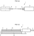
図1は、本発明の第1実施形態の応力センサの構成を示す説明図であり、(a)は応力センサを上面から見た図、(b)は応力センサの側面の断面図である。図1に示す応力センサ1は、光ファイバ2と、保護皮膜層3と、コネクタ4と、基板としてのベース5と、管6と、接着層7とを備える。
[First Embodiment]
1A and 1B are explanatory views showing the configuration of the stress sensor according to the first embodiment of the present invention, in which FIG. 1A is a view of the stress sensor as viewed from above, and FIG. 1B is a sectional view of a side surface of the stress sensor. A
光ファイバ2の一部には凹凸が形成されている。その凹凸は、光ファイバ2の一部の表面にざらつきを持たせるような形態で形成されている。凹凸の形成された光ファイバ2の凹凸部2aでは、凹凸の形成されていない光ファイバ2と比較して、マイクロベンディング現象による光の漏出が促進される。光ファイバ2の凹凸は、例えば研磨剤を用いた研磨により形成される。この光ファイバ2の表面の凹凸は、フッ化水素酸などによる侵食により形成することも可能である。
Unevenness is formed on a part of the
保護皮膜層3(図1(a)では図示省略)は紫外線や水分、あるいは、異物との接触による損傷などから光ファイバ2を保護するための皮膜層である。保護皮膜層3は光ファイバ2の凹凸部2aを覆うように設けられている。
The protective coating layer 3 (not shown in FIG. 1A) is a coating layer for protecting the
コネクタ4は、光ファイバ2の一端部に装着されており、このコネクタ4に後述する可視光源8が着脱自在に接続されている。
The
ベース5は、可撓性を有すると共に、板状に形成されている。部材には、エポキシをはじめとしたポリアミドイミドなどの樹脂が用いられる。ベース5は取付面5aと接着面5bとを有し、この接着面5b上に光ファイバ2の凹凸部2aが配置されている。ベース5は、接着面5bと被検知部9とを接着剤で固定することにより、被検知部9に固着される。
The
管6はベース5の接着面5bの端部に固定されており、この管6に光ファイバ2が挿入されている。そのため、ベース5の接着面5bの端部付近で光ファイバ2の屈曲を防止することができる。
The
接着層7は、光ファイバ2とベース5との間で層状に設けられており、可撓性を有している。この接着層7により、光ファイバ2とベース5とが固定されている。接着層7は、例えば、エポキシ系の接着剤を層状に塗布することにより形成される。
The
可視光源8は、光ファイバ2に導入する可視光を発生させる光源であり、具体的には赤色レーザーが用いられている。可視光源8から発生される可視光は、光ファイバ2の内部に導入される。
The visible
以上の構成の応力センサ1では、光ファイバ2の凹凸部2aが固定されたベース5の取付面5aが、応力の発生を検知しようとする被検知部9に接着剤(図示省略)により固着される。これにより、光ファイバ2の凹凸部2aは、被検知部9に発生する応力がベース5を介して伝達されるように該被検知部9に装着される。
In the
又、光ファイバ2の凹凸部2aを被検知部9に装着した状態で、光ファイバ2に可視光を導入し、可視光の導入状態で、被検知部9における光ファイバ2の表面からの可視光の漏れを視覚的に監視し、可視光の漏れが視覚的に認識された場合に被検知部9における応力の発生を検知することで、被検知部9に発生する応力を検知することができる。
Further, visible light is introduced into the
このとき、被検知部9に発生する応力により光ファイバ2が屈曲されると、装着された光ファイバ2に可視光が導入されることにより、マイクロペンディング現象が凹凸部2aで促進されて、光ファイバ2から漏出した可視光が視覚的に認識できるようになる。
At this time, when the
なお、本実施形態は、光ファイバ2をベース5に貼り付けて、このベース5を被検知部9に固着しているが、ベース5を用いずに光ファイバ2の凹凸部2aを直接的に被検知部9に装着することも可能である。光ファイバ2と被検知部9との装着には、接着剤などが用いられる。
In this embodiment, the
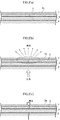
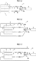
図2は第1実施形態の応力センサの発光状態を説明する説明図である。図2(a)は被検知部9の応力発生前の状態、図2(b)は被検知部9の応力発生時の状態、図2(c)は応力により被検知部9にひび割れが生じた状態を示している。
FIG. 2 is an explanatory view illustrating the light emission state of the stress sensor of the first embodiment. 2A is a state before the stress is generated in the detected
図2(a)に示すように、ベース5を固着した被検知部9に応力が生じていない状態では、光ファイバ2を貼り付けたベース5は屈曲されていないため、光ファイバ2は屈曲しない。そのため、マイクロペンディング現象は光ファイバ2で生じておらず、可視光源8から入力された可視光は光ファイバ2の凹凸部2aで漏出しない。
As shown in FIG. 2A, the
又、図2(b)に示すように、被検知部9に応力が生じてベース5が屈曲すると、ベース5に固定されている光ファイバ2が屈曲する。その際、光ファイバ2の凹凸部2aでマイクロペンディング現象が促進されるため、光ファイバ2から漏出した可視光を視覚的に認識することができる。
As shown in FIG. 2B, when stress is generated in the detected
被検知部9に生じた応力が大きくなるにつれてベース5の屈曲が大きくなるため、被検知部9に生じた応力が大きくなるにつれて光ファイバ2の屈曲が大きくなる。そのため、被検知部9に生じた応力が大きいときは光ファイバ2で漏出する可視光が強くなり、被検知部9に生じた応力が小さいときは光ファイバ2で漏出する可視光が弱くなる。
Since the bending of the
又、図2(c)に示すように、被検知部9に生じる応力がさらに大きくなり、被検知部9に大きなひずみあるいはひび割れが生じると、ベース5に固定されている光ファイバ2が破断する。そのため、可視光源8から入力された可視光が破断箇所から漏出して、可視光を視覚的に認識することが可能となる。破断箇所で視覚的に認識することができる可視光は、マイクロペンディング現象により視覚的に認識することができる可視光よりも強い。
Further, as shown in FIG. 2C, when the stress generated in the detected
以上のように、被検知部9に応力が発生すると、該応力が光ファイバ2の破断には至らない程度の応力であっても、光ファイバ2の凹凸部2aから漏出する可視光によって、該応力の発生を検知できる。
As described above, when stress is generated in the detected
[第2実施形態]
図3は、本発明の第2実施形態の応力センサの構成を示す説明図であり、応力センサの側面の断面図である。図3に示す応力センサ1は、第1実施形態の応力センサ1と共通する構成を有しているため、以下の説明では、第1実施形態と同一の構成については、第1実施形態と同一の参照符号を用いて説明を省略する。
[Second Embodiment]
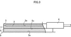
FIG. 3 is an explanatory diagram showing the configuration of the stress sensor according to the second embodiment of the present invention, and is a cross-sectional view of a side surface of the stress sensor. Since the
図3に示す応力センサ1では、ベース5の接着面5cに凹凸が形成されている。このため、被検知部9に生じている応力が効率よく光ファイバ2に伝達される。したがって、被検出部9に生じている応力をより感度よく検知することができる。ベース5の表面の凹凸は、例えば研磨剤を用いた研磨により形成される。
In the
[応力検知システムの構成]
次に、複数の被検知部9の応力を検知する応力検知システム11の例について説明する。
[Configuration of stress detection system]
Next, an example of the
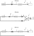
図4(a)、(b)、(c)には、図1に示す応力センサ1を複数配設した応力検知システム11が示されている。図4(a)は、2つの応力センサの光ファイバが直列に接続された応力検知システムである。この応力検知システム11は、複数の、例えば2個の応力センサ1と、可視光源8とから構成されている。夫々の応力センサ1の光ファイバ2は直列に接続されており、直列体12を形成している。又、光ファイバ2の一端部にはコネクタ4が装着されており、このコネクタ4に可視光源8が着脱自在に接続されている。そのため、1つの可視光源8から各応力センサ1の光ファイバ2に可視光を導入できる。なお、それぞれの応力センサ1の光ファイバ2を共通の単一の光ファイバ2で構成してもよい。
4A, 4B, and 4C show a
図4(b)は、2つの応力センサの光ファイバが直列に接続されると共に、光ファイバの両端が互いに近接するよう延設された応力検知システムである。図4(b)の応力検知システム11は、可視光源8と、複数の応力センサ1と、コネクタ4と、光カプラ13とを有している。光カプラ13は1つの入力部13aと複数の(図示例では2つの)出力部13bとを有している。
FIG. 4B shows a stress detection system in which optical fibers of two stress sensors are connected in series and both ends of the optical fibers are extended close to each other. The
光カプラ13の入力部13aには、接続用光ファイバ22aの一端部が接続されている。この接続用光ファイバ22の他端部にはコネクタ4aが装着されており、このコネクタ4aを介して接続用光ファイバ22aが可視光源8に接続されている。又、光カプラ13の各出力部13bには、接続用光ファイバ22bの一端部が接続されている。この接続用光ファイバ22bの他端部にはコネクタ4bが装着されており、このコネクタ4bが応力センサ1のコネクタ4に接続されている。かかる構成により、可視光源8からの可視光は、光カプラ13で分配されて各々の応力センサ1に供給される。
One end of a connection
図4(b)に示される応力センサ1は可視光源8に対して直列に接続されている。そのため、1つの可視光源8から各応力センサ1の光ファイバ2に可視光を導入できる。さらに、直列体12の両端部が光カプラ13を介して可視光源8に接続されるので、1つの応力センサ1の光ファイバ2が応力の増大により破断しても、他の応力センサ1の光ファイバ2に支障なく可視光が導入される。
The
図4(c)の応力検知システム11は、複数の、例えば2つの応力センサの光ファイバが直列に接続された応力検知システムである。この応力検知システム11は、2個の応力センサ1と、可視光源8とから構成されている。夫々の応力センサ1は直列に接続されており、直列体12を形成している。又、光ファイバ2の一端部にはコネクタ4が装着されており、このコネクタ4に可視光源8が着脱自在に接続されている。そのため、1つの可視光源8から各応力センサ1の光ファイバ2に可視光を導入できる。
The
又、直列体12を構成する光ファイバ2の両端部がベース5上から逸脱しており、その両端部が近接している。各応力センサ1の光ファイバ2の両端部が近接しているので、単一の可視光源8から各応力センサ1の光ファイバ2にその一端部から可視光を供給したとき、該可視光源8の設置場所において、各応力センサ1の光ファイバ2の他端部から可視光が導出するか否かを視覚的に認識することができる。ひいては、各応力センサ1の光ファイバ2を正常に可視光が通過しているか否かを確認できる。又、図4(b)のものと同様に、1つの応力センサの光ファイバ2が披検知部9で破断しても、他の応力センサ1の光ファイバ2に支障なく可視光を供給できる。
Further, both end portions of the
図5(a)、(b)、(c)には、図1に示す応力センサ1を複数配設した応力検知システム11が示されている。図5(a)は、2つの応力センサの光ファイバが並列に接続された応力検知システムである。この応力検知システム11は、2個の応力センサ1と、可視光源8と、コネクタ4と、光カプラ13とを有している。光カプラ13は1つの入力部13aと複数の(図示例では2つの)出力部13bを有している。
FIGS. 5A, 5B, and 5C show a
光カプラ13の入力部13aには、接続用光ファイバ22aの一端部が接続されている。この接続用光ファイバ22aの他端部にはコネクタ4aが装着されており、このコネクタ4aを介して接続用光ファイバ22aが可視光源8に接続されている。又、光カプラ13の各出力部13bには、接続用光ファイバ22bの一端部が接続されている。この接続用光ファイバ22bの他端部にはコネクタ4bが装着されており、このコネクタ4bが応力センサ1のコネクタ4に接続されている。かかる構成により、可視光源8からの可視光は、光カプラ13で分配されて各々の応力センサ1に供給される。
One end of a connection
図5(a)に示される応力センサ1は可視光源8に対して並列に接続されている。そのため、1つの可視光源8から各応力センサ1の光ファイバ2に可視光を導入できる。さらに、1つの応力センサ1の光ファイバ2が応力の増大により破断しても、他の応力センサ1の光ファイバ2に支障なくに可視光が導入される。
The
図5(b)は、夫々の応力センサ1が並列に接続された応力検知システム11である。図5(b)の応力検知システム11は、可視光源8と、複数の応力センサ1と、コネクタ4と、光カプラ13とを有している。光カプラ13は1つの入力部13aと複数の(図示例では4つの)出力部13bを有している。
FIG. 5B shows a
光カプラ13の入力部13aには、接続用光ファイバ22aの一端部が接続されている。この接続用光ファイバ22aの他端部にはコネクタ4aが装着されており、このコネクタ4aを介して接続用光ファイバ22aが可視光源8に接続されている。又、光カプラ13の各出力部13bには、接続用光ファイバ22bの一端部が接続されている。この接続用光ファイバ22bの他端部にはコネクタ4bが装着されており、このコネクタ4bが応力センサ1のコネクタ4に接続されている。
One end of a connection
図5(b)に示される各応力センサ1は、その光ファイバ2の両端部がベース5上から逸脱しており、その両端部にそれぞれコネクタ4が装着されている。又、各応力センサ1の光ファイバ2の両端部は近接している。
In each
各応力センサ1の光ファイバ2の両端部がそれぞれ光カプラ13を介して可視光源8に接続されている。このため、各応力センサ1の光ファイバ2にはその両端部から可視光が導入される。このため、各応力センサ1の光ファイバ2は、ベース5を固着した被検知部9との光カプラ13との間で破断しても、光ファイバ2の凹凸部2aに可視光を供給できる。
Both ends of the
又、各応力センサ1の光ファイバ2の両端部が近接しているので、可視光源8の設置場所を動かすことなく、各応力センサ1の光ファイバ2が被検知部9で破断しても、他の応力センサ1の光ファイバ2に支障なく可視光を供給できる。
In addition, since both ends of the
図5(c)の応力検知システム11は、可視光源8と、一つの入力部13a及び複数の(図示例では2つの)出力部13bを有する光カプラ13と、複数の応力センサ1と、コネクタ4とを有している。
The
光カプラ13の入力部13aには、接続用光ファイバ22aの一端部が接続されている。この接続用光ファイバ22aの他端部にはコネクタ4aが装着されており、このコネクタ4aを介して接続用光ファイバ22aが可視光源8に接続されている。又、光カプラ13の各出力部13bには、接続用光ファイバ22bの一端部が接続されている。この接続用光ファイバ22bの他端部にはコネクタ4bが装着されており、このコネクタ4bが応力センサ1のコネクタ4に接続されている。かかる構成により、可視光源8からの可視光は、光カプラ13で分配されて各々の応力センサ1に供給される。
One end of a connection
図5(c)に示される各応力センサ1は、その光ファイバ2の両端部がベース5上から逸脱しており、その両端部が近接している。各応力センサ1の光ファイバ2の両端部が近接しているので、単一の可視光源8から各応力センサ1の光ファイバ2にその一端部から可視光を供給したとき、該可視光源8の設置場所において、各応力センサ1の光ファイバ2の他端部から可視光が導出するか否かを視覚的に認識できる。ひいては、各応力センサ1の光ファイバ2を正常に可視光が通過しているか否かを確認できる。又、図5(b)のものと同様に、1つの応力センサ1の光ファイバ2が被検知部9で破断しても、他の応力センサ1の光ファイバ2に支障なく可視光を供給できる。
In each
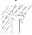
図6には、図1に示す応力センサ1を橋梁に複数配設した応力検知システム11の施工例が示されている。応力センサ1は、被検知部9である橋梁において大きな応力の生じやすい箇所、例えば溶接部に固着される。応力センサ1は、応力の生じやすい箇所毎に固着される。又、各々の応力センサ1は、コネクタ4同士を接続させることにより直列若しくは並列に接続させることができる。又、橋梁には、可視光源8が取り付けられており、この可視光源8と各々の応力センサ1とは、光ファイバ2により接続されている。可視光源8からの可視光を光ファイバ2に導入することにより、各々の応力センサ1に可視光が導入される。そして、応力センサ1から漏出される可視光の位置と強さとから、橋梁に生じている応力とひずみを検知することができる。
FIG. 6 shows a construction example of the
図7には、図1に示す応力センサ1を被検知部9であるガス管に複数配設した応力検知システム11の施工例が示されている。応力センサ1は、被検出部であるガス管の管部の外周に沿って固着される。このとき、応力センサ1と管部とは、光ファイバ2の屈曲が最小となるように被検知部9に固着される。この応力センサ1は、可視光源8からの可視光が光ファイバ2に導入されることにより、可視光が応力やひずみの生じている箇所で漏出する。この可視光の位置と強さとから、被検知部9に生じている応力とひずみを検知することができる。
FIG. 7 shows a construction example of the
[応力検出部の施工方法]
次に、応力検出部の施工方法の一例について説明する。
[Construction method of stress detection part]
Next, an example of the construction method of a stress detection part is demonstrated.
光ファイバ2のマイクロベンディング現象による光の漏出を促進する凹凸を付ける工程では、まず、光ファイバ2の周囲を覆う被覆がある場合には、被覆を剥がす工程が実行される。被覆の剥離はファイバストリッパを用いて実行される。なお、被覆がない場合には、この作業は不要である。
In the step of forming irregularities that promote light leakage due to the microbending phenomenon of the
次に、光ファイバ2の被検知部9に装着しようとする部分の表面に凹凸を形成する工程が実行される。凹凸の形成は、研磨剤を用いることにより実行される。又、凹凸の形成は、研磨材の代わりに薬品によるエッチングで実行されてもよい。凹凸の形成された光ファイバ2は、十分に洗浄される。
Next, a step of forming irregularities on the surface of the portion of the
凹凸を付けた光ファイバ2を被検知部9に貼着する工程では、まず、被検知部9と接触する光ファイバ2の凹凸部2aに接着剤が塗布される。次に、接着剤を塗布した光ファイバ2の凹凸部2aを被検知部9に貼着する工程が実行される。光ファイバ2を被検知部9に貼着する際には、光ファイバ2の凹凸部2aは視覚的に認識可能となる位置に設けられる。なお、被検知部9に接着剤を塗布した後に、その塗布箇所に光ファイバ2の凹凸部2aを貼着してもよい。その後、光ファイバ2を覆うように保護皮膜層3が貼り付けられる。応力センサ1と可視光源8との間の配線には、必要に応じてコネクタ4が用いられる。
In the step of attaching the uneven
このような応力検出部の施工方法により、予め凹凸が付された専用的な光ファイバを使用せずとも、汎用的な光ファイバを用いて現場における施工作業を行なうことができる。なお、光ファイバに凹凸を付することは、汎用的な研磨剤などを使用して容易に行なうことができる。 By such a stress detection unit construction method, construction work can be performed on site using a general-purpose optical fiber without using a dedicated optical fiber with irregularities in advance. It should be noted that the unevenness of the optical fiber can be easily performed using a general-purpose abrasive or the like.
又、光ファイバ2は、ベース5を介して被検知部9に貼着することも可能である。その際、光ファイバ2を貼着する工程では、まず被検知部9に応じた大きさにベース5を切断する工程が実施される。ベース5は容易に切断できる樹脂で構成されているため、被検出部9の位置と大きさに応じて、カッター等を用いてベース5の形状と大きさとを任意に切り出すことができる。次に、切り出されたベース5が十分に洗浄された後、ベース5が接着剤により被検知部9に貼着される。
Further, the
次に、光ファイバ2の凹凸部2aをベース5に貼着する工程が実施される。その際、光ファイバ2の凹凸部2aとベース5とがそれらのいずれかに塗布された接着剤からなる接着層7を介して貼着される。又、光ファイバ2とベース5との貼着の次の工程で、光ファイバ2と接着層7とを覆うように保護皮膜層3がベース5上に貼り付けられる。光ファイバ2を被検知部9に貼着する際には、光ファイバ2の凹凸部2aは視覚的に認識可能となる位置に貼着される。
Next, the process of sticking the uneven | corrugated |
このような応力検出部の施工方法により、凹凸を付けた光ファイバ2の部分を貼り付ける面(基板の表面)を、その貼り付けに適した面にすることができるので、光ファイバ2の凹凸部2aを基板を介して被検知部に装着することを適切に行うことができる。
By such a stress detection unit construction method, the surface (surface of the substrate) to which the portion of the
1…応力センサ、2、22a、22b…光ファイバ、2a…凹凸部、3…保護皮膜層、4…コネクタ、5…ベース、7…接着層、8…可視光源、9…被検知部、11…応力検知システム、12…直列体、13…光カプラ。
DESCRIPTION OF
Claims (11)
該光ファイバの前記被検知部に装着される部分の表面にマイクロベンディング現象による光の漏出を促進する凹凸部を設けたことを特徴とする応力センサ。 An optical fiber that is at least partially attached to the detected part and in which visible light is introduced so that stress generated in the detected part is transmitted;
A stress sensor, characterized in that an uneven portion for promoting light leakage due to a microbending phenomenon is provided on a surface of a portion of the optical fiber attached to the detected portion.
前記光ファイバの凹凸部を表面に貼り付けた可撓性の基板を備え、該基板を前記被検知部に固着することによって前記凹凸部が該基板を介して前記被検知部に装着されることを特徴とする応力センサ。 The stress sensor according to claim 1,
A flexible substrate having a concavo-convex portion of the optical fiber attached to a surface thereof, and the concavo-convex portion being attached to the detected portion via the substrate by fixing the substrate to the detected portion; Stress sensor characterized by.
前記基板の前記光ファイバを貼り付ける表面に凹凸部を設けたことを特徴とする応力センサ。 The stress sensor according to claim 2, wherein
A stress sensor, wherein an uneven portion is provided on a surface of the substrate to which the optical fiber is attached.
前記光ファイバの前記凹凸部を前記被検知部に装着した状態で、該光ファイバに可視光を導入し、該可視光の導入状態で、当該被検知部における前記光ファイバの表面からの可視光の漏れを視覚的に監視し、該可視光の漏れが視覚的に認識された場合に当該被検知部における応力の発生を検知することを特徴とする応力検知方法。 A method for detecting stress generated in the detected portion using the stress sensor according to claim 1,
Visible light is introduced from the surface of the optical fiber in the detected portion in the state where the visible light is introduced in a state where the uneven portion of the optical fiber is attached to the detected portion. A stress detection method comprising: visually monitoring leakage of light and detecting occurrence of stress in the detected portion when the leakage of visible light is visually recognized.
該光分配供給手段の各出力部は、各前記応力センサの光ファイバの一端に接続されていることを特徴とする応力検知システム。 A plurality of the stress sensors according to any one of claims 1 to 3, and a light distribution supply unit that distributes and supplies input visible light from a plurality of output units,
Each output part of the light distribution and supply means is connected to one end of an optical fiber of each stress sensor.
該凹凸を付けた光ファイバの部分を、被検知部に生じる応力が伝達されるように該被検知部に装着する工程とからなる、応力検出部の施工方法。 Providing a surface of at least a part of an optical fiber into which visible light can be introduced with unevenness that promotes leakage of light due to a microbending phenomenon of the optical fiber;
A method for constructing the stress detecting unit, comprising: attaching the uneven portion of the optical fiber to the detected part so that the stress generated in the detected part is transmitted.
前記光ファイバを装着する工程では、前記被検知部に予め固着した可撓性の基板上に、前記凹凸を付けた光ファイバの部分を接着剤で貼り付けることを特徴とする施工方法。 In the construction method of Claim 10,
In the step of attaching the optical fiber, the construction method is characterized in that the portion of the optical fiber with the unevenness is pasted with an adhesive on a flexible substrate fixed to the detected portion in advance.
Priority Applications (1)
| Application Number | Priority Date | Filing Date | Title |
|---|---|---|---|
| JP2009262361A JP2011106966A (en) | 2009-11-17 | 2009-11-17 | Stress sensor, method of detecting stress, stress detection system, and method of constructing stress detector |
Applications Claiming Priority (1)
| Application Number | Priority Date | Filing Date | Title |
|---|---|---|---|
| JP2009262361A JP2011106966A (en) | 2009-11-17 | 2009-11-17 | Stress sensor, method of detecting stress, stress detection system, and method of constructing stress detector |
Publications (1)
| Publication Number | Publication Date |
|---|---|
| JP2011106966A true JP2011106966A (en) | 2011-06-02 |
Family
ID=44230612
Family Applications (1)
| Application Number | Title | Priority Date | Filing Date |
|---|---|---|---|
| JP2009262361A Pending JP2011106966A (en) | 2009-11-17 | 2009-11-17 | Stress sensor, method of detecting stress, stress detection system, and method of constructing stress detector |
Country Status (1)
| Country | Link |
|---|---|
| JP (1) | JP2011106966A (en) |
Cited By (1)
| Publication number | Priority date | Publication date | Assignee | Title |
|---|---|---|---|---|
| JPWO2013062075A1 (en) * | 2011-10-26 | 2015-04-02 | 出光興産株式会社 | ORGANIC ELECTROLUMINESCENT DEVICE AND MATERIAL FOR ORGANIC ELECTROLUMINESCENT DEVICE |
Citations (4)
| Publication number | Priority date | Publication date | Assignee | Title |
|---|---|---|---|---|
| JPH01291102A (en) * | 1988-05-18 | 1989-11-22 | Honda Motor Co Ltd | Optical sensor device |
| JPH041540A (en) * | 1990-04-12 | 1992-01-07 | Fuji Electric Co Ltd | Force sensor |
| JPH11344358A (en) * | 1998-03-30 | 1999-12-14 | Furukawa Electric Co Ltd:The | Measurement system using optical fiber Bragg grating |
| JP2007248213A (en) * | 2006-03-15 | 2007-09-27 | Fujikura Ltd | Bending sensor |
-
2009
- 2009-11-17 JP JP2009262361A patent/JP2011106966A/en active Pending
Patent Citations (4)
| Publication number | Priority date | Publication date | Assignee | Title |
|---|---|---|---|---|
| JPH01291102A (en) * | 1988-05-18 | 1989-11-22 | Honda Motor Co Ltd | Optical sensor device |
| JPH041540A (en) * | 1990-04-12 | 1992-01-07 | Fuji Electric Co Ltd | Force sensor |
| JPH11344358A (en) * | 1998-03-30 | 1999-12-14 | Furukawa Electric Co Ltd:The | Measurement system using optical fiber Bragg grating |
| JP2007248213A (en) * | 2006-03-15 | 2007-09-27 | Fujikura Ltd | Bending sensor |
Cited By (1)
| Publication number | Priority date | Publication date | Assignee | Title |
|---|---|---|---|---|
| JPWO2013062075A1 (en) * | 2011-10-26 | 2015-04-02 | 出光興産株式会社 | ORGANIC ELECTROLUMINESCENT DEVICE AND MATERIAL FOR ORGANIC ELECTROLUMINESCENT DEVICE |
Similar Documents
| Publication | Publication Date | Title |
|---|---|---|
| KR100449399B1 (en) | Surfacial strain sensor and method for confirming of damage proceeding in concrete structure | |
| JP6599703B2 (en) | Underground type reinforced plastic lining double shell tank | |
| JP4027258B2 (en) | Debonding inspection method for bonded parts | |
| JP2005098921A (en) | Damage detection system for structural composite material and damage detection method for structural composite material | |
| CN101561430A (en) | System for monitoring crack of piezoelectric-array converged alertness network structure and monitoring and installing methods | |
| JP5399310B2 (en) | Crack detection sensor | |
| CN113008127B (en) | Monitoring methods of liquid-cooled charging cables, liquid-cooled charging cables and charging stations | |
| JP3457894B2 (en) | Optical fiber laying method and strain detecting device using optical fiber | |
| JP6301963B2 (en) | Strain sensor and installation method of strain sensor | |
| KR20090042012A (en) | System for structure safety supervision | |
| JP4366403B2 (en) | Strain sensor and strain detection system | |
| JP2002081061A (en) | Load control method for ground anchor | |
| KR20110032127A (en) | Fiber optic cable integrated tape (or sheet) for pipeline damage detection and construction method | |
| ES2409942B1 (en) | METHODS OF DAMAGE LOCATION IN AEROGENERATING PALES | |
| KR20150050910A (en) | System for monitoring a process | |
| JPH11326149A (en) | How to check the progress of damage after reinforcement of concrete structures | |
| JP2011107050A (en) | Device and method for monitoring pipe leakage | |
| JPH11325822A (en) | Crack monitoring equipment | |
| CN203572503U (en) | Installation device for fiber grating components of slope stability monitoring system | |
| JP2016121958A (en) | Water leakage detection system, water leakage detection device, and water leakage detection method | |
| JP3242154U (en) | Optical cable connecting device | |
| WO2017150457A1 (en) | Optical fiber holding sheet | |
| TWI381152B (en) | Vibration sensing method for fiber optic grating | |
| JP2007132746A (en) | Optical fiber sensor and strain / temperature observation system | |
| IT202000005347A1 (en) | Conductor for bare overhead power lines with a composite material core and real-time monitoring system for checking the structural integrity of the conductor during production, laying and installation |
Legal Events
| Date | Code | Title | Description |
|---|---|---|---|
| A621 | Written request for application examination |
Effective date: 20121109 Free format text: JAPANESE INTERMEDIATE CODE: A621 |
|
| A977 | Report on retrieval |
Free format text: JAPANESE INTERMEDIATE CODE: A971007 Effective date: 20131225 |
|
| A131 | Notification of reasons for refusal |
Free format text: JAPANESE INTERMEDIATE CODE: A131 Effective date: 20140107 |
|
| A02 | Decision of refusal |
Free format text: JAPANESE INTERMEDIATE CODE: A02 Effective date: 20140527 |