JP2011106906A - Running speed detector and power transmission device including the same - Google Patents
Running speed detector and power transmission device including the same Download PDFInfo
- Publication number
- JP2011106906A JP2011106906A JP2009260779A JP2009260779A JP2011106906A JP 2011106906 A JP2011106906 A JP 2011106906A JP 2009260779 A JP2009260779 A JP 2009260779A JP 2009260779 A JP2009260779 A JP 2009260779A JP 2011106906 A JP2011106906 A JP 2011106906A
- Authority
- JP
- Japan
- Prior art keywords
- pulley
- chain
- effective radius
- transmission member
- traveling speed
- Prior art date
- Legal status (The legal status is an assumption and is not a legal conclusion. Google has not performed a legal analysis and makes no representation as to the accuracy of the status listed.)
- Pending
Links
Images

Landscapes
- Transmissions By Endless Flexible Members (AREA)
Abstract
【課題】振動や騒音を確実に抑制することに寄与することができる走行速度検出装置を提供する。
【解決手段】第1および第2のプーリ2,3間に巻き掛けられたチェーン4の弦領域4bの振動を抑制するスタビライザ17が、弦領域4bを挿通させる挿通路25を区画し、弦領域4bによって支持されている。弦領域4bの姿勢変化等に対する追従性の高いスタビライザ17に、第1および第2の変位センサ18,19を支持した。変位センサ18,19は、チェーン4の走行に伴う凹凸変化に基づいて走行速度Vに相関のある信号を出力する。
【選択図】図1A traveling speed detecting device that can contribute to reliably suppressing vibration and noise.
A stabilizer 17 for suppressing vibration of a string region 4b of a chain 4 wound between first and second pulleys 2 and 3 defines an insertion passage 25 through which the string region 4b is inserted. It is supported by 4b. The first and second displacement sensors 18 and 19 are supported by the stabilizer 17 having high followability to the posture change of the string region 4b. The displacement sensors 18 and 19 output a signal having a correlation with the traveling speed V based on the unevenness change accompanying traveling of the chain 4.
[Selection] Figure 1
Description
本発明は走行速度検出装置およびこれを備える動力伝達装置に関する。 The present invention relates to a traveling speed detection device and a power transmission device including the same.
動力伝達装置として、プライマリープーリと、セカンダリープーリと、これらプライマリープーリおよびセカンダリープーリの間に巻き掛けられたチェーン等の伝動部材と、これらを収容するケーシングとを備える無段変速機がある。各プーリは、固定シーブおよび可動シーブにより構成され、各シーブはそれぞれ円錐面状シーブ面を有している。
この種の動力伝達装置では、伝動部材のうちプーリ間にある弦領域(直線領域)は、プーリにより動きを規制されていないので、振動(いわゆる弦振動)を生じ易い。特に、伝動部材がプーリに噛み込むときやプーリから離脱するとき(すなわち伝動部材の拘束状態と非拘束状態とが切り換わるとき)において、伝動部材の姿勢変化が激しく、これにより弦振動を引き起し易い。弦振動が生ずると、騒音の原因となる。
As a power transmission device, there is a continuously variable transmission that includes a primary pulley, a secondary pulley, a transmission member such as a chain wound between the primary pulley and the secondary pulley, and a casing that houses them. Each pulley includes a fixed sheave and a movable sheave, and each sheave has a conical sheave surface.
In this type of power transmission device, the string region (straight region) between the pulleys of the transmission member is not restricted by the pulleys, and thus vibration (so-called string vibration) is likely to occur. In particular, when the transmission member is engaged with the pulley or detached from the pulley (that is, when the transmission member is switched between the constrained state and the non-restrained state), the posture change of the transmission member is severe, which causes string vibration. Easy to do. When string vibration occurs, it causes noise.
そこで、上記の弦振動を低減するため、ケーシングによって支持され、伝動部材の弦領域の動きを規制するガイドレールを備える無段変速機が提案されている(例えば特許文献1を参照)。 Therefore, in order to reduce the above string vibration, a continuously variable transmission including a guide rail that is supported by a casing and restricts the movement of the string region of the transmission member has been proposed (for example, see Patent Document 1).
ところで、プーリに対する伝動部材の巻き掛け径(プーリの有効半径に相当)が小さくなり過ぎてプーリの中心軸の外径部に干渉する場合が想定される。逆に有効半径が大きくなり過ぎてケーシングの内径部に干渉したり、プーリの外径を超えて伝動部材(例えばチェーンの場合、リンク間を連結するピン)がはみ出す場合が想定される。
このような場合、いずれも伝動部材の動作が不安定となり、振動や騒音を発生する。しかしながら、従来、上記のような現象を事前にコントロールする方法がなかった。
By the way, it is assumed that the winding diameter of the transmission member with respect to the pulley (corresponding to the effective radius of the pulley) becomes too small and interferes with the outer diameter portion of the central axis of the pulley. On the other hand, it is assumed that the effective radius becomes too large and interferes with the inner diameter portion of the casing, or the transmission member (for example, a pin connecting the links in the case of a chain) protrudes beyond the outer diameter of the pulley.
In such a case, the operation of the transmission member becomes unstable in all cases, and vibration and noise are generated. However, there has conventionally been no method for controlling the above phenomenon in advance.
本発明は、かかる背景のもとになされたものであり、振動や騒音を確実に抑制することに寄与することができる走行速度検出装置およびこれを備える動力伝達装置を提供することを目的とする。 The present invention has been made based on such a background, and an object thereof is to provide a traveling speed detection device that can contribute to reliably suppressing vibration and noise, and a power transmission device including the traveling speed detection device. .
上記目的を達成するため、本発明は、第1および第2のプーリ(2,3)間に巻き掛けられた伝動部材(4)の走行速度(V)を検出する走行速度検出装置(6)において、上記伝動部材の弦領域(4b)を挿通させる挿通路(25)を区画して上記弦領域によって支持され、上記弦領域の振動を抑制するスタビライザ(17)と、上記スタビライザによって支持され、上記伝動部材の走行に伴う凹凸変化に基づいて上記走行速度に相関のある信号を出力する変位センサ(18,19)と、を備える走行速度検出装置を提供するものである。 In order to achieve the above object, the present invention provides a traveling speed detecting device (6) for detecting a traveling speed (V) of a transmission member (4) wound between first and second pulleys (2, 3). And a stabilizer (17) that is supported by the string region by partitioning an insertion path (25) through which the string region (4b) of the transmission member is inserted, and is supported by the stabilizer, Disclosed is a travel speed detecting device including a displacement sensor (18, 19) that outputs a signal having a correlation with the travel speed based on a change in unevenness caused by travel of the transmission member.
本発明によれば下記の利点がある。すなわち、弦領域を挿通させる挿通路を区画する状態で上記弦領域によって支持されたスタビライザは、弦領域の姿勢変化等の動きに対する追従性が高い。このように弦領域の動きに対する追従性が高いスタビライザに、伝動部材の走行速度を検出するための信号を出力する変位センサを支持したので、弦領域の傾斜角度等の変化に拘らず、変位センサを弦領域に対して精度の良い位置に保持することができる。したがって、伝動部材の走行速度を精度良く検出することができる。このように精度良く検出された走行速度を用いて、伝動部材に関するプーリの有効半径を求めて、これを制御することも可能となり、ひいては、プーリの中心軸に対する伝動部材の干渉や、ケーシングの内径部への伝動部材の干渉や、プーリの外径からの伝動部材のはみ出し等を確実に防止して騒音を低減することに寄与することができる。 The present invention has the following advantages. That is, the stabilizer supported by the chord area in a state where the insertion path for inserting the chord area is defined has high followability to movement such as a change in posture of the chord area. Since the displacement sensor that outputs a signal for detecting the traveling speed of the transmission member is supported on the stabilizer having high followability with respect to the movement of the string region in this way, the displacement sensor can be used regardless of changes in the inclination angle of the string region. Can be held at an accurate position with respect to the chord region. Therefore, the traveling speed of the transmission member can be detected with high accuracy. It is possible to obtain and control the effective radius of the pulley related to the transmission member by using the traveling speed thus detected accurately, and consequently, the interference of the transmission member with respect to the central axis of the pulley and the inner diameter of the casing. It is possible to contribute to the reduction of noise by reliably preventing the transmission member from interfering with the part and the transmission member protruding from the outer diameter of the pulley.
また、上記変位センサにより検出された信号に基づいて上記伝動部材の走行速度を検出する走行速度検出手段(20)を備える場合がある(請求項2)。この場合、変位センサからの信号を用いて走行速度を検出することができる。
伝動部材としての例えばチェーンは、走行方向に隣接するリンク同士をピンにより連結して構成されているので、走行方向に隣接するリンクが順次に変位センサに対向する領域を通過することになる。変位センサは各リンクの通過による凹凸変化を検出することができる。
Further, there may be provided traveling speed detecting means (20) for detecting the traveling speed of the transmission member based on a signal detected by the displacement sensor (claim 2). In this case, the traveling speed can be detected using a signal from the displacement sensor.
For example, a chain as a transmission member is configured by connecting links adjacent to each other in the traveling direction with pins, so that the links adjacent to the traveling direction sequentially pass through a region facing the displacement sensor. The displacement sensor can detect the unevenness change due to the passage of each link.
変位センサとして単一の変位センサを用いてもよいし、複数の変位センサを用いてもよい。例えば、上記伝動部材の走行方向(X)に離隔する第1および第2の変位センサ(18,19)を含んいでいてもよい(請求項3)。伝動部材としての例えばチェーンでは、リンク同士を連結するピンがプーリ間に噛み込まれるときの打音を低減するために、ピン間のピッチ(連結ピッチ)として、短ピッチと長ピッチとを設ける場合がある。第1および第2の変位センサが上記走行方向に離隔する間隔を上記短ピッチに対応する所定の間隔に設定することにより、例えば、短ピッチのリンクの通過のみに基づいて伝動部材の走行速度を検出することが可能となる。すなわち、噛み込み音をより低減できるようにピン間のピッチが複数種、設定されている場合にも、伝動部材の走行速度を精度良く検出することができ、可及的に騒音をより低減することができる。 A single displacement sensor may be used as the displacement sensor, or a plurality of displacement sensors may be used. For example, you may include the 1st and 2nd displacement sensor (18, 19) spaced apart in the running direction (X) of the said transmission member (Claim 3). For example, in a chain as a transmission member, a short pitch and a long pitch are provided as the pitch between pins (connection pitch) in order to reduce the hitting sound when the pins connecting the links are caught between pulleys. There is. By setting the interval at which the first and second displacement sensors are separated in the traveling direction to a predetermined interval corresponding to the short pitch, for example, the traveling speed of the transmission member is set based only on the passage of the short pitch link. It becomes possible to detect. That is, even when a plurality of types of pitches between pins are set so that the biting sound can be further reduced, the traveling speed of the transmission member can be detected with high accuracy, and the noise is further reduced as much as possible. be able to.
また、本発明は、上記走行速度検出装置を備える動力伝達装置(1)において、各プーリの回転速度をそれぞれ検出する回転速度検出手段(7,8)と、上記走行速度検出手段により検出された上記走行速度と上記回転速度検出手段により検出された各プーリの回転速度(N1,N2)との比較に基づいて、伝動部材に関する各プーリの有効半径(R1,R2)を演算する有効半径演算手段(31,32)と、を備える動力伝達装置を提供する(請求項4)。本発明では、例えば第1のプーリの回転速度N1と伝動部材の走行速度Vとを用いて、第1のプーリの有効半径R1を式R1=V/N1により精度良く求めることができる。 In the power transmission device (1) provided with the travel speed detection device, the present invention is detected by the rotational speed detection means (7, 8) for detecting the rotational speed of each pulley and the travel speed detection means. Effective radius calculating means for calculating the effective radius (R1, R2) of each pulley related to the transmission member based on the comparison between the traveling speed and the rotating speed (N1, N2) of each pulley detected by the rotating speed detecting means. (31, 32) is provided. (Claim 4) In the present invention, for example, the effective radius R1 of the first pulley can be accurately obtained by the equation R1 = V / N1 using the rotational speed N1 of the first pulley and the traveling speed V of the transmission member.
また、上記有効半径演算部により演算された有効半径が所定範囲を逸脱しないように各プーリのクランプ力を制御するクランプ力制御手段(33,34)を備えるを備える場合がある(請求項5)。この場合、プーリの有効半径が上記所定範囲の上限値を超えないように、また下限値を下回らないように、プーリのクランプ力を制御することにより、プーリの中心軸に対する伝動部材の干渉や、ケーシングの内径部への伝動部材の干渉や、プーリの外径からの伝動部材のはみ出し等を確実に防止して騒音を低減することができる。 Further, there may be provided a clamping force control means (33, 34) for controlling the clamping force of each pulley so that the effective radius calculated by the effective radius calculation unit does not deviate from a predetermined range. . In this case, by controlling the clamping force of the pulley so that the effective radius of the pulley does not exceed the upper limit value of the predetermined range and does not fall below the lower limit value, interference of the transmission member with respect to the central axis of the pulley, Noise can be reduced by reliably preventing the interference of the transmission member to the inner diameter portion of the casing, the protrusion of the transmission member from the outer diameter of the pulley, and the like.
なお、上記において、括弧内の英数字は、後述する実施形態における対応構成要素の参照符号を表すものであるが、これらの参照符号により特許請求の範囲を限定する趣旨ではない。 In the above description, the alphanumeric characters in parentheses represent reference numerals of corresponding components in the embodiments described later, but the scope of the claims is not limited by these reference numerals.
以下では、図面を参照して、本発明の実施形態について具体的に説明する。
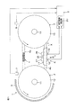
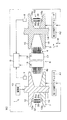
図1は、本発明の一実施形態に係る走行速度検出装置を含む、動力伝達装置としての無段変速機の概略構成を示す模式的側面図である。また、図2は、無段変速機1の一部破断模式的下面図である。
図1および図2を参照して、無段変速機1は、自動車等の車両に搭載されるものであり、第1のプーリ2(プライマリープーリ)と、第2のプーリ3(センカダリープーリ)と、両プーリ2,3間に巻き掛けられた無端状の伝動部材としてのチェーン4と、両プーリ2,3およびチェーン4を収容したケーシング5と、チェーン4の走行速度Vを検出する走行速度検出装置6と、第1のプーリ2の回転速度N1を検出する第1の回転速度センサ7と、第2のプーリ3の回転速度N2を検出する第2の回転速度センサ8と、走行速度検出装置6並びに第1および第2の回転速度センサ7,8からの信号に基づいて、各プーリ2,3のクランプ力を制御する制御部9とを備えている。
Hereinafter, embodiments of the present invention will be described in detail with reference to the drawings.
FIG. 1 is a schematic side view showing a schematic configuration of a continuously variable transmission as a power transmission device including a traveling speed detection device according to an embodiment of the present invention. FIG. 2 is a partially broken schematic bottom view of the continuously
Referring to FIGS. 1 and 2, a continuously
チェーン4は、直線領域として、例えば上側となる張り側の弦領域4aと、例えば下側となる弛み側の弦領域4bとを備えている。本実施の形態の主たる特徴は、走行速度検出装置6が、例えば弦領域4bによって支持され弦領域4bの振動(弦振動)を抑制するように上記弦領域4bを挿通させた例えば筒状のスタビライザ17と、そのスタビライザ17に取り付けられ、チェーン4の走行に伴う凹凸変化を検出する第1および第2の変位センサ18,19と、第1および第2の変位センサ18,19からの信号に基づいて走行速度を検出する走行速度検出手段としての走行速度検出部20(制御部9に設けられる)とを備える点にある。
The
本実施の形態では、走行速度検出装置6のスタビライザ17が、弛み側の弦領域4bに取り付けられる場合に則して説明するが、上記のスタビライザ17を、張り側の弦領域4aおよび弛み側の弦領域4bの双方に取り付けるようにしてもよいし、張り側の弦領域4aのみに取り付けるようにしてもよい。
第1のプーリ2は、車両の駆動源10に動力伝達可能に連なる入力軸11(第1のプーリ2の中心軸に相当)に同行回転可能に取り付けられている。第1のプーリ2は、シーブ面12aを有する固定シーブ12と、シーブ面13aを有する可動シーブ13とを備えている。一対のシーブ面12a,13aは互いに対向している。これらシーブ面12a,13a間に溝G1が形成されている。チェーン4は、この溝G1内において、一対のシーブ面12a,13a間に強圧に挟まれて保持されている。
In the present embodiment, the
The
可動シーブ13には、溝幅(溝G1の幅)を変更するための第1の油圧アクチュエータA1が接続されている。第1の油圧アクチュエータA1は、入力軸11の軸方向に可動シーブ13を移動させて、溝幅を変化させることができる。溝幅を変化させることで、入力軸11の径方向にチェーン4を移動させて、第1のプーリ2のチェーン4に関する有効半径(以下、「第1のプーリ2の有効半径」ともいう。)を変更させることができる。
The
一方、第2のプーリ3は、駆動輪( 図示せず)に動力伝達可能に連なる出力軸14(第2のプーリ3の中心軸に相当)に同行回転可能に取り付けられている。第2のプーリ3は、シーブ面15aを有する固定シーブ15と、シーブ面16aを有する可動シーブ16とを備えている。一対のシーブ面15a,16aは互いに対向している。これらシーブ面15a,16a間に溝G2が形成されている。チェーン4は、この溝G2内において、一対のシーブ面15a,16a間に強圧に挟まれて保持されている。
On the other hand, the
第2のプーリ3の可動シーブ16には、第2の油圧アクチュエータA2が接続されている。第2の油圧アクチュエータA2は、溝幅(溝G2の幅)を変化させることで、出力軸14の径方向にチェーン4を移動させて、第2のプーリ3のチェーン4に関する有効半径(以下、「第2のプーリ3の有効半径」ともいう。)を変更させることができる。
駆動源10から入力軸11に回転駆動力が入力されると、入力軸11および第1のプーリ2が同行回転する。そして、この第1のプーリ2の回転は、チェーン4を介して、第2のプーリ3に伝達される。無段変速機1は、第1のプーリ2の有効半径および第2のプーリ3の有効半径を変更させることにより、変速比(第2のプーリ3の回転速度/第1のプーリ2の回転速度)を連続的に変化させることができる。
A second hydraulic actuator A2 is connected to the
When a rotational driving force is input from the
走行速度検出装置6は、伝動部材としてのチェーン4の弦領域4bに沿って姿勢変化可能に支持され弦領域4bの振動を抑制するスタビライザ17と、そのスタビライザ17によって支持され、チェーン4の走行に伴う凹凸変化を検出可能な第1および第2変位センサ18,19と、上記制御部9に設けられ、第1および第2の変位センサ18,19からの信号に基づいて、チェーン4の走行速度Vを検出する走行速度検出部20とを備えている。
The travel speed detection device 6 is supported by the
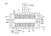
図3および図3のIV−IV線に沿う断面図である図4を参照して、スタビライザ17は、チェーン4の弦領域4bが若干の遊びを有して挿通可能なように、チェーン4の弦領域4bに沿って延びる例えば断面方形の長尺の筒状に形成されている。スタビライザ17は、例えば2つ割り形状とされて、両プーリ2,3間に巻き掛けられた後のチェーン4に取り付けられる。スタビライザ17の材質は金属でもよいし、合成樹脂でもよい。2つ割り形状を一体化するには、嵌め合わせでもよいし、溶接または融着でもよいし、ねじ止めとしてもよい。
Referring to FIG. 4, which is a cross-sectional view taken along the line IV-IV in FIGS. 3 and 3, the
スタビライザ17は、チェーン4の内周に対向する内対向壁21と、チェーン4の外周に対向する外対向壁22と、内対向壁21および外対向壁22の対向端部間をそれぞれ連結する一対の側壁23,24とを有している。これら内対向壁21、外対向壁22および一対の側壁23,24によって、チェーン4の弦領域4bを挿通させる挿通路25が区画されている。
The
また、図1および図3を参照して、スタビライザ17は、チェーン4の走行方向Xへの移動に伴ってその移動方向に移動可能とされているとともに、走行方向Xおよびその反対方向に関して、所定量以上の移動が規制部材26により規制されている。具体的には、規制部材26は、内対向壁21に対向するようにケーシング5に固定されており、スタビライザ17の内対向壁21には、規制部材26を挟んで走行方向Xに離隔する被規制部としての一対の被規制突起27,28が設けられている。
1 and 3, the
規制部材26は、変速に拘らずその位置が概ね変化しないチェーン4の領域(具体的には、後述する図6の中間点P2に相当)に対向するように配置されている。規制部材26は、上記のように走行方向Xに関するスタビライザ17の移動量を規制する機能の他、走行方向X(図3参照)およびチェーン4の幅方向W(図4参照)の双方と交差(直交)する弦振動方向Yの一方(内方)へのスタビライザ17の移動量を規制している。
The restricting
また、上記の第1および第2の変位センサ18,19は、スタビライザ17の外対向壁22に、スタビライザ17の長手方向に相当する走行方向Xに離隔するように取り付けられている。具体的には、各変位センサ18,19は、外対向壁22を厚み方向に貫通する保持孔29,30に保持されており、その検出面18a,19aをチェーン4の所定部(チェーン4の幅方向Wの端部におけるリンク35の下縁部)に対向させている。各変位センサ18,19は、走行するチェーン4の上記所定部の変位を検出する。
The first and
すなわち、各変位センサ18,19は、チェーン4の上記所定部の通過による凹凸変化に伴って、チェーン4の走行速度に相関のあるパルス信号を出力するパルスセンサとして機能する。各変位センサ18,19としては、非接触式である光学センサを用いることが好ましい。
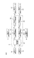
図5に示すように、制御部9は、走行速度検出部20により検出されたチェーン4の走行速度Vと、第1の回転速度センサ7により検出された第1のプーリ2の回転速度N1とに基づいて、式R1=V/N1を用いて、第1のプーリ2の有効半径R1を演算する有効半径演算手段としての第1の有効半径演算部31を備えている。
That is, each
As shown in FIG. 5, the
また、制御部9は、走行速度検出部20により検出されたチェーン4の走行速度Vと、第2の回転速度センサ8により検出された第2のプーリ3の回転速度N2とに基づいて、式R2=V/N2を用いて、第2のプーリ3の有効半径R2を演算する有効半径演算手段としての第2の有効半径演算部32を備えている。
また、制御部9は、第1の有効半径演算部31により演算された有効半径R1が所定範囲を逸脱しないように、すなわち、有効半径R1が、下限値R1Lと上限値R1Hとの間に保持されるように(R1L≦R1≦R1H)、第1のプーリ2のクランプ力を制御するクランプ力制御手段としての第1のクランプ力制御部33を備えている。
Further, the
Further, the
具体的には、第1のクランプ力制御部33は、第1の有効半径演算部31から与えられた有効半径R1がR1Hに達すると、クランプ力を減少するように第1の油圧アクチュエータA1を制御することにより、有効半径R1が上限値R1Hを上回ることを防止する。また、第1のクランプ力制御部33は、第1の有効半径演算部31から与えられた有効半径R1がR1Lに達すると、クランプ力を増大するように第1の油圧アクチュエータA1を制御することにより、有効半径R1が下限値R1Lを下回ることを防止する。
Specifically, the first clamping
また、制御部9は、第2の有効半径演算部32により演算された有効半径R2が所定範囲を逸脱しないように、すなわち、有効半径R2が、下限値R2Lと上限値R2Hとの間に保持されるように(R2L≦R2≦R2H)、第2のプーリ3のクランプ力を制御するクランプ力制御手段としての第2のクランプ力制御部34を備えている。
具体的には、第2のクランプ力制御部34は、第2の有効半径演算部32から与えられた有効半径R2がR2Hに達すると、クランプ力を減少するように第2の油圧アクチュエータA2を制御することにより、有効半径R2が上限値R2Hを上回ることを防止する。また、第2のクランプ力制御部34は、第2の有効半径演算部32から与えられた有効半径R2がR2Lに達すると、クランプ力を増大するように第2の油圧アクチュエータA2を制御することにより、有効半径R2が下限値R2Lを下回ることを防止する。
In addition, the
Specifically, the second clamping
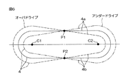
図6は、チェーン4の模式的な側面図であり、第1のプーリ2の中心軸線C1(第1のプーリ2の中心軸としての入力軸11の中心軸線に相当)および第2のプーリ3の中心軸線C2(第2のプーリ3の中心軸としての出力軸14の中心軸線に相当)に平行な方向に沿ってチェーン4を見た概略図である。
図6において、実線で示されたチェーン4は、無段変速機1の変速比が1であるとき(等速時)のチェーン4の位置を示している。また、二点鎖線で示されたチェーン4は、アンダードライブ時で且つ無段変速機1の減速比が最も高いときのチェーン4の位置を示している。また、破線で示されたチェーン4は、オーバードライブ時で且つ無段変速機1の増速比が最も高いときのチェーン4の位置を示している。
FIG. 6 is a schematic side view of the
In FIG. 6, the
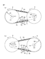
図6の破線および図7(a)に示されるオーバードライブ時で且つ増速比が最大のときには、第1のプーリ2の有効半径R1が最大とされ、第2のプーリ3の有効半径R2が最小とされる。各弦領域4a,4bにおけるチェーン4の傾斜角は、増速比の変化に伴って変化していき、オーバードライブ時において、増速比が最大のときに最大値となる。
図6の一点鎖線および図7(b)に示されるアンダードライブ時で且つ減速比が最大のときには、第1のプーリ2の有効半径R1が最小とされ、第2のプーリ3の有効半径R2が最大とされる。各弦領域4a,4bにおけるチェーン4の傾斜角は、減速比の変化に伴って変化していき、アンダードライブ時において、減速比が最大のときに最大値となる。
When the overdrive shown in the broken line in FIG. 6 and FIG. 7A is performed and the speed increasing ratio is maximum, the effective radius R1 of the
When the underdrive shown in FIG. 6 and the underdrive shown in FIG. 7B and when the reduction ratio is maximum, the effective radius R1 of the
図6に示すように、張り側の弦領域4aが、無段変速機1の変速比の変化に伴って、当該弦領域4aの中間点P1を回動中心として回動する。また、弛み側の弦領域4bが、無段変速機1の変速比の変化に伴って、当該弦領域4bの中間点P2を回動中心として回動する。
中間点P1,P2は、各プーリ2,3の中心軸線C1,C2と平行な方向に沿ってみた場合に、変速に拘らず位置が概ね変化しない位置となっている。走行速度検出装置6のスタビライザ17の走行方向Xへの移動を規制する規制部材26は、図7(a)に示すオーバードライブで且つ増速比が最大のときと図7(b)に示すアンダードライブで且つ減速比が最大のときとの間で、位置が概ね変化しない、弦領域4bの中間点P2に対向する位置に配置されている。
As shown in FIG. 6, the
The intermediate points P1 and P2 are positions where the positions do not substantially change regardless of the speed change when viewed along a direction parallel to the central axes C1 and C2 of the
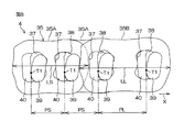
次いで、図8は、チェーン4の一部の側面図である。図8を参照して、チェーン4は、複数のリンク35と、これらのリンク35を互いに屈曲可能に連結する複数の連結部材36とを備えている。各リンク35は、概ね矩形状に形成された例えば鋼板製の板状の部材である。図8に示すように、各リンク35には、走行方向Xの前後に並ぶ前貫通孔37および後貫通孔38が形成されている。
Next, FIG. 8 is a side view of a part of the
リンク35は、互いに平行とされた状態でチェーン4の幅方向Wに並べられている。リンク35は、複数の列を形成している。これらの列は、走行方向Xに並んで配置されている。走行方向Xに隣接するリンク35を幅方向Wから見ると、後方側のリンク35の前貫通孔37と前方側のリンク35の後貫通孔38とは、互いに重なり合っている。各連結部材36は、幅方向Wに重なり合う複数の前貫通孔37および後貫通孔38に嵌合されている。走行方向Xに隣接するリンク35は、連結部材36によって、互いに屈曲可能に連結されている。
The
各連結部材36は、第1の動力伝達部材としての第1のピン39と、この第1のピン39と対をなす第2の動力伝達部材としての第2のピン40とを含む。第1および第2のピン39,40は、それぞれ、幅方向Wに延びる長尺(板状)の部材である。第1および第2のピン39,40は、例えば、軸受用鋼(SUJ)等の高強度耐摩耗材料で形成されている。対をなす第1および第2のピン39,40は、対応するリンク35間の屈曲に伴い、互いに転がり摺動接触するようになっている。転がり摺動接触とは、転がり接触およびすべり接触の少なくとも一方を含む接触状態をいう。
Each connecting member 36 includes a
図4に示すように、第1のピン39は、第2のピン40よりも長くされている。第1のピン39の一対の端面39a,39bは、それぞれ、第2のピン40の一対の端面40a,40bよりもチェーン4の幅方向Wの外側に突出している。
図2を参照して、第1のピン39は、一対のシーブ面(シーブ面12aとシーブ面13a、または、シーブ面15aとシーブ面16a)間に挟持される。第2のピン40の一対の端面40a,40bは、図示していないが、各プーリ2,3の対応するシーブ面12a,13a,15a,16aに潤滑油膜を介して摩擦接触(係合)する。
As shown in FIG. 4, the
Referring to FIG. 2,
駆動源10から第1のプーリ2に入力された駆動力は、第1のピン39の一対の端面39a,39bを介して、チェーン4に伝達される。また、チェーン4に伝達された駆動力は、第1のピン39の一対の端面39a,39bを介して、第2のプーリ3に伝達される。
再び図8を参照して、上記の複数のリンク35は、連結ピッチPSを有する短ピッチリンク35Aと、短ピッチリンク35Aの連結ピッチPSよりも長い連結ピッチPLを有する長ピッチリンク35Bとを含んでいる。
The driving force input to the
Referring to FIG. 8 again, the plurality of
ここで、短ピッチリンク35Aの連結ピッチPSとは、弦領域4bの短ピッチリンク35Aにおける、隣り合う第1のピン39間の距離をいう。具体的には、弦領域4bの短ピッチリンク35Aの前貫通孔37内の第1および第2のピン39,40の互いの接触部T1と、当該短ピッチリンク35Aの後貫通孔38内の第1および第2のピン39,40の互いの接触部T1との間の、走行方向Xの距離をいう。
Here, the connection pitch PS of the
長ピッチリンク35Bの連結ピッチPLとは、弦領域4bの長ピッチリンク35Bにおける、隣り合う第1のピン39間の距離をいう。具体的には、弦領域4bの長ピッチリンク35Bの前貫通孔37内の第1および第2のピン39,40の互いの接触部T1と、当該長ピッチリンク35Bの後貫通孔38内の第1および第2のピン39,40の互いの接触部T1との間の、走行方向Xの距離をいう。
The connection pitch PL of the
このように連結ピッチが相異なる2種類のリンク35A,35Bを用いることにより、各第1のピン39が順次に第1のプーリ2または第2のプーリ3に係合する際の係合音の周期を不均一にし、また、各第1のピン39が第1のプーリ2または第2のプーリ3に順次に係合する際の周波数を広範囲に分布させ、騒音を低減させるようにしている。短ピッチリンク35Aおよび長ピッチリンク35Bは、走行方向Xにランダムに配置されていれば好ましい。
By using the two types of
本実施の形態において、上記のように走行方向Xに離隔する第1および第2の変位センサ18,19を用いるのは、リンク35が短ピッチリンク35Aと長ピッチリンク35Bを含む場合に対応するためであり、走行方向Xに関する第1および第2の変位センサ18,19間の距離Lが、短ピッチリンク35Aの通過のみを検出するのに適した距離に設定されている。
In the present embodiment, the use of the first and
具体的には、距離Lが、走行方向Xに関する短ピッチリンク35Aのリンク長LSよりも長く且つ長ピッチリンク35Bのリンク長LLよりも短い距離に設定されている(LS<L<LL)。これにより、長ピッチリンク35Bが通過するときは、第1の変位センサ18から出力されるパルスと第2の変位センサ19から出力されるパルスが同時になる領域がある。そこで、同時になる領域のあるパルス出力はカンウトしないで、同時になる領域のないパルス出力のみをカンウトすることにより、短ピッチリンク35Aの通過回数のみを検出することが可能となる。したがって、単位時間当たりの短ピッチリンク35Aの通過回数に基づいてチェーン4の走行速度Vを求めることができる。
Specifically, the distance L is set to a distance that is longer than the link length LS of the
本実施の形態によれば、弦領域4bの挿通路25を区画する筒状のスタビライザ17により弦領域4bの振動を抑制することができる。
また、弦領域4bを挿通させる挿通路25を区画する状態で弦領域4bによって支持されたスタビライザ17は、弦領域4bの姿勢変化等の動きに対する追従性が高い。このように弦領域4bの動きに対する追従性が高いスタビライザ17に、チェーン4の走行速度Vを検出するための信号を出力する変位センサ18,19を支持したので、弦領域4bの傾斜角度等の変化に拘らず、変位センサ18,19を弦領域4bに対して精度の良い位置に保持することができる。したがって、チェーン4の走行速度Vを精度良く検出することができる。
According to the present embodiment, the vibration of the
In addition, the
このように精度良く検出された走行速度Vを用いて、各プーリ2,3のチェーン4に関する有効半径R1,R2を求めて、これらの有効半径R1,R2を制御することも可能となり、ひいては、プーリ2,3の中心軸に対するチェーン4の干渉や、ケーシング5の内径部へのチェーン4の干渉や、プーリ2,3の外径からのチェーン4の第1のピン39のはみ出し等を確実に防止して騒音を低減することができる。
It is possible to obtain effective radii R1 and R2 related to the
また、変位センサとして、チェーン4の走行方向Xに離隔する第1および第2の変位センサ18,19を用いるので、噛み込み音の低減のためにリンク35として、連結ピッチの相異なるリンク(例えば短ピッチリンク35A、長ピッチリンク35B)が設けられている場合に、例えば、短ピッチリンク35Aの通過のみに基づいてチェーン4の走行速度Vを検出することが可能となる。すなわち、噛み込み音をより低減できるように連結ピッチが複数種設定されている場合にも、チェーン4の走行速度を精度良く検出することができ、可及的に騒音をより低減することができる。
In addition, since the first and
また、本実施の形態の無段変速機1では、走行速度検出手段6により検出された走行速度Vと各回転速度センサ7,8により検出された各プーリ2,3の回転速度N1,N2との比較に基づいて、各プーリ2,3の有効半径R1,R2を演算するので、各プーリ2,3の有効半径R1,R2を精度良く求めることができる。
さらに、このように精度良く求められた有効半径R1,R2が所定範囲を逸脱しないように各プーリ2,3のクランプ力を制御する。具体的には、有効半径R1,R2が上記所定範囲の上限値R1H,R2Hをそれぞれ超えないように、また有効半径R1,R2が上記所定範囲の下限値R1L,R2Lをそれぞれ下回らないように、各プーリ2,3のクランプ力を制御する。したがって、各プーリ2,3の中心軸に相当する入力軸11や出力軸14に対するチェーン4の干渉や、ケーシング5の内径部へのチェーン4の干渉や、各プーリ2,3の外径からのチェーン4のはみ出し等を確実に防止して騒音を低減することができる。
Further, in the continuously
Further, the clamping forces of the
さらに、スタビライザ7は弦領域4bによって支持され、ケーシング5には支持されないので、弦領域4bの固有振動数を高くすることができる。したがって、仮に可聴域ではあっても耳障りな音ではない周波数域(例えば8000Hz以上)に固有振動数を設定することも可能となり、不快感のない騒音特性に向上することができる。また、スタビライザ7が弦領域によって支持されるので、ケーシング5等への組み付け作業が不要となり、組立性が向上し、製造コストを安くすることができる。
Furthermore, since the
本発明は上記実施の形態に限定されるものではない。例えば上記の実施の形態では、相異なる連結ピッチを有するリンクを用いていたので、2つの変位センサを用いたが、単一の連結ピッチを有するリンクを用いる場合には、単一の変位センサを用いればよい。
また、上記の実施の形態では、変位センサ18,19がチェーン4のリンク35の通過に伴う凹凸変化を検出したが、これに限らない。例えば、第1のピン39が第2のピン40よりも、チェーン4の幅方向Wの外方へ突出しているので、第1のピン39の端面39aまたは39bに対向する変位センサを用いて、第1のピン39および第2のピン40の通過に伴う凹凸変化を検出するようにしてもよい。その場合、第1および第2の変位センサ18,19間の距離Lは、短ピッチリンク35Aの連結ピッチPSよりも長く、且つ長ピッチリンク35Bの連結ピッチPLよりも短く設定されることが好ましい(PS<L<PL)。
The present invention is not limited to the above embodiment. For example, in the above embodiment, since links having different connection pitches are used, two displacement sensors are used. However, when a link having a single connection pitch is used, a single displacement sensor is used. Use it.
Further, in the above embodiment, the
なお、上記の実施の形態では、図1に示すように、上側の弦領域が張り側の弦領域4aであり、下側の弦領域が弛み側の弦領域4bであったが、第1および第2のプーリ2,3が図1の回転方向とは逆方向に回転する場合には、上側の弦領域が弛み側の弦領域4bとなり、下側の弦領域が張り側の弦領域4aとなる。
また、伝動部材として、チェーンに代えて、ベルトを用いるようにしてもよい。その他、本発明は、請求項記載の範囲内において種々の変更が可能である。
In the above embodiment, as shown in FIG. 1, the upper chord region is the
Further, a belt may be used as the transmission member instead of the chain. In addition, the present invention can be variously modified within the scope of the claims.
1…無段変速機(動力伝達装置)、2…第1のプーリ、3…第2のプーリ、4…チェーン(伝動部材)、4a…(張り側の)弦領域、4b…(弛み側の)弦領域、5…ケーシング、6…走行速度検出装置、7…第1の回転速度センサ(第1の回転速度検出手段)、8…第2の回転速度センサ(第2の回転速度検出手段)、9…制御部、11…入力軸、12…固定シーブ、13…可動シーブ、14…出力軸、15…固定シーブ、16…可動シーブ、17…スタビライザ、18…第1の変位センサ、19…第2の変位センサ、20…走行速度検出部(走行速度検出手段)、21…内対向壁、22…外対向壁、23,24…側壁、25…挿通路、26…規制部材、27,28…被規制突起(被規制部材)、31…第1の有効半径演算部(有効半径演算手段)、32…第2の有効半径演算部(有効半径演算手段)、33…第1のクランプ力制御部(クランプ力制御手段)、34…第2のクランプ力制御部(クランプ力制御手段)、35…リンク、35A…短ピッチリンク、35B…長ピッチリンク、36…連結部材、37…前貫通孔、38…後貫通孔、39…第1のピン、40…第2のピン、A1…第1の油圧アクチュエータ、A2…第2の油圧アクチュエータ、L…(第1および第2の変位センサ間の)距離、LS…(短ピッチリンクの)リンク長、LL…(長ピッチリンクの)のリンク長、PS…(短ピッチリンクの)連結ピッチ、PL…(長ピッチリンクの)連結ピッチ、W…幅方向、X…(弦領域の)走行方向、Y…弦振動方向
DESCRIPTION OF
Claims (5)
上記伝動部材の弦領域を挿通させる挿通路を区画して上記弦領域によって支持され、上記弦領域の振動を抑制するスタビライザと、
上記スタビライザによって支持され、上記伝動部材の走行に伴う凹凸変化に基づいて上記走行速度に相関のある信号を出力する変位センサと、を備えることを特徴とする走行速度検出装置。 In the traveling speed detection device that detects the traveling speed of the transmission member wound between the first and second pulleys,
A stabilizer that divides an insertion path through which the string region of the transmission member is inserted and is supported by the string region, and suppresses vibration of the string region;
A travel speed detection device comprising: a displacement sensor supported by the stabilizer and outputting a signal correlated with the travel speed based on a change in unevenness caused by travel of the transmission member.
各プーリの回転速度をそれぞれ検出する回転速度検出手段と、
上記走行速度検出手段により検出された上記走行速度と上記回転速度検出手段により検出された各プーリの回転速度との比較に基づいて、伝動部材に関する各プーリの有効半径を演算する有効半径演算手段と、を備えることを特徴とする動力伝達装置。 In the power transmission device comprising the traveling speed detection device according to any one of claims 1 to 3,
A rotational speed detecting means for detecting the rotational speed of each pulley;
Effective radius calculating means for calculating an effective radius of each pulley related to the transmission member based on a comparison between the traveling speed detected by the traveling speed detecting means and the rotational speed of each pulley detected by the rotational speed detecting means; A power transmission device comprising:
Priority Applications (1)
| Application Number | Priority Date | Filing Date | Title |
|---|---|---|---|
| JP2009260779A JP2011106906A (en) | 2009-11-16 | 2009-11-16 | Running speed detector and power transmission device including the same |
Applications Claiming Priority (1)
| Application Number | Priority Date | Filing Date | Title |
|---|---|---|---|
| JP2009260779A JP2011106906A (en) | 2009-11-16 | 2009-11-16 | Running speed detector and power transmission device including the same |
Publications (1)
| Publication Number | Publication Date |
|---|---|
| JP2011106906A true JP2011106906A (en) | 2011-06-02 |
Family
ID=44230556
Family Applications (1)
| Application Number | Title | Priority Date | Filing Date |
|---|---|---|---|
| JP2009260779A Pending JP2011106906A (en) | 2009-11-16 | 2009-11-16 | Running speed detector and power transmission device including the same |
Country Status (1)
| Country | Link |
|---|---|
| JP (1) | JP2011106906A (en) |
Cited By (3)
| Publication number | Priority date | Publication date | Assignee | Title |
|---|---|---|---|---|
| JP2021004772A (en) * | 2019-06-25 | 2021-01-14 | ジヤトコ株式会社 | Rotation speed measuring apparatus |
| JP2021004773A (en) * | 2019-06-25 | 2021-01-14 | ジヤトコ株式会社 | Rotation speed measuring apparatus |
| CN118177785A (en) * | 2024-03-18 | 2024-06-14 | 南京宽乐健康科技有限公司 | A pace measuring instrument |
-
2009
- 2009-11-16 JP JP2009260779A patent/JP2011106906A/en active Pending
Cited By (5)
| Publication number | Priority date | Publication date | Assignee | Title |
|---|---|---|---|---|
| JP2021004772A (en) * | 2019-06-25 | 2021-01-14 | ジヤトコ株式会社 | Rotation speed measuring apparatus |
| JP2021004773A (en) * | 2019-06-25 | 2021-01-14 | ジヤトコ株式会社 | Rotation speed measuring apparatus |
| JP7280762B2 (en) | 2019-06-25 | 2023-05-24 | ジヤトコ株式会社 | Rotational speed measuring device |
| JP7280761B2 (en) | 2019-06-25 | 2023-05-24 | ジヤトコ株式会社 | Rotational speed measuring device |
| CN118177785A (en) * | 2024-03-18 | 2024-06-14 | 南京宽乐健康科技有限公司 | A pace measuring instrument |
Similar Documents
| Publication | Publication Date | Title |
|---|---|---|
| US7354364B2 (en) | Apparatus for detecting the speed of an endless torque-transmitting member of a continuously variable transmission | |
| EP2085643B1 (en) | Method and apparatus for pre-tensioning a power transmission chain | |
| JP6160631B2 (en) | Lubricating device for belt type continuously variable transmission | |
| JP5347290B2 (en) | Power transmission chain pretension method | |
| JP2009156341A (en) | Chain abnormality monitoring device | |
| JP5160096B2 (en) | Power transmission chain and power transmission device including the same | |
| JP5408492B2 (en) | Stabilizer device | |
| JPWO2005085673A1 (en) | Power transmission chain and power transmission device | |
| JP2011112154A (en) | Power transmission device | |
| JP5866754B2 (en) | Power transmission device | |
| JP2011112155A (en) | Stabilizer device and power transmission device | |
| JP2009156300A (en) | Chain speed detection device and chain speed detection method | |
| JP4591764B2 (en) | Power transmission chain and power transmission device including the same | |
| JP2005291322A (en) | Power transmission chain and power transmission device equipped with it | |
| JP4946462B2 (en) | Power transmission device | |
| US11391343B2 (en) | Continuously variable transmission | |
| JP2006226452A (en) | Power transmission chain and power transmission device including the same | |
| JP2011112086A (en) | Stabilizer | |
| JP5494092B2 (en) | Manufacturing method of power transmission chain | |
| JP4560954B2 (en) | Endless belt for transmission | |
| JP4893562B2 (en) | Power transmission chain and power transmission device | |
| JP2006097856A (en) | Power transmission chain and power transmission device including the same | |
| JP2006214554A (en) | Power transmission chain and power transmission device including the same | |
| JP2009257487A (en) | Power transmission chain and power transmission device | |
| JP2006138452A (en) | Power transmission chain and power transmission device |