JP2011106905A - Flaw detection system - Google Patents
Flaw detection system Download PDFInfo
- Publication number
- JP2011106905A JP2011106905A JP2009260744A JP2009260744A JP2011106905A JP 2011106905 A JP2011106905 A JP 2011106905A JP 2009260744 A JP2009260744 A JP 2009260744A JP 2009260744 A JP2009260744 A JP 2009260744A JP 2011106905 A JP2011106905 A JP 2011106905A
- Authority
- JP
- Japan
- Prior art keywords
- probe
- position information
- robot
- information
- flaw detection
- Prior art date
- Legal status (The legal status is an assumption and is not a legal conclusion. Google has not performed a legal analysis and makes no representation as to the accuracy of the status listed.)
- Granted
Links
Images

Landscapes
- Investigating Or Analyzing Materials By The Use Of Ultrasonic Waves (AREA)
Abstract
【課題】システム1の簡略化を図りつつも、高精度の探傷結果が得られる探傷システムを実現する。
【解決手段】探傷システム1は、多関節ロボット4と、走行軸51上でロボット4を移動させる走行装置5と、ロボット4の手首に取り付けられたプローブ31と、ロボット4の位置に関する情報を所定周期で出力する走行装置位置情報取得器52と、プローブ31の位置に関する情報を所定周期で出力するロボット位置情報取得器41と、プローブ31の位置情報を算出して出力する制御器42と、プローブの位置情報と探傷情報とを対応付ける探傷器43と、を備える。取得したプローブの位置情報と実際の位置との許容ずれ量をDとしたときに、条件式(1)を満たすように、許容ずれ量D、上限周期Tmax、プローブの移動速度V、及び、ワークの形状の走行軸に対する変化率r、をそれぞれ設定する。
【数1】
![]()
【選択図】図1A flaw detection system capable of obtaining a highly accurate flaw detection result while simplifying a system.
A flaw detection system (1) provides predetermined information about an articulated robot (4), a traveling device (5) for moving the robot (4) on a traveling axis (51), a probe (31) attached to the wrist of the robot (4), and the position of the robot (4). A traveling device position information acquisition unit 52 that outputs at a cycle, a robot position information acquisition unit 41 that outputs information about the position of the probe 31 at a predetermined cycle, a controller 42 that calculates and outputs the position information of the probe 31, and a probe A flaw detector 43 for associating the position information with the flaw detection information. When the allowable deviation amount between the acquired position information of the probe and the actual position is D, the allowable deviation amount D, the upper limit period Tmax, the probe moving speed V, and the workpiece so as to satisfy the conditional expression (1) The rate of change r with respect to the travel axis of the shape is set.
[Expression 1]
![]()
[Selection] Figure 1
Description
ここに開示する技術は、特に三次元形状を有するワークの探傷検査を行う、探傷システムに関する。 The technology disclosed herein relates to a flaw detection system that performs flaw detection inspection of a workpiece having a three-dimensional shape.
従来より、被検査物に対する探傷検査を行うシステムの例として超音波探傷システムが知られており、例えば特許文献1には、多関節ロボットが、手首に取り付けた探触子を被検査物の表面を倣うように移動させることによって、当該被検査物の探傷情報を取得するシステムが開示されている。こうした超音波探傷検査では、被検査物のどの位置に内部欠陥等が存在しているかを把握する必要があるため、探傷情報と、それを取得した位置情報とを対応付ける必要がある。そのため、前記特許文献に開示されたシステムでは、ロボット制御装置が出力する取り込みタイミング信号に基づいて、探触子の位置情報と探傷情報とをそれぞれ独立して取得する一方で、それら探触子の位置情報と探傷情報とを互いに対応付ける処理を行うようにしている。
2. Description of the Related Art Conventionally, an ultrasonic flaw detection system is known as an example of a flaw detection inspection system for an object to be inspected. For example, in
ところが、前記特許文献に記載システムでは、取り込みタイミング信号に基づいて探触子の位置情報を取得しようとすれば、探触子の位置情報をリアルタイムで取得しなければならないが、多関節ロボット、特に汎用のロボットは、手首に取り付けた探触子の位置情報をリアルタイムに取得することができない。つまり、位置情報の取得に要する時間が変動してしまうため、所望のタイミングで位置情報を取得しようとしても、その位置情報が取得できないことが起こり得る。位置情報が取得できなかった場合には、探触子の位置情報が更新されないから、取得した探触子の位置情報と、探触子の実際の位置との間にずれが生じてしまい、結果として、ずれを含んだ位置情報と探傷情報とが対応付けられてしまう。このことは、検査結果において、内部欠陥の位置が、実際とは、ずれて示されることになり、探傷検査結果の位置精度を低下させる。 However, in the system described in the above-mentioned patent document, if it is attempted to acquire the position information of the probe based on the capture timing signal, the position information of the probe must be acquired in real time. The general-purpose robot cannot acquire the position information of the probe attached to the wrist in real time. That is, since the time required to acquire the position information varies, it may happen that the position information cannot be acquired even if the position information is acquired at a desired timing. If the position information cannot be acquired, the position information of the probe is not updated.Therefore, a deviation occurs between the acquired position information of the probe and the actual position of the probe. As a result, the position information including the deviation and the flaw detection information are associated with each other. This indicates that the position of the internal defect is shifted from the actual position in the inspection result, and the position accuracy of the flaw detection inspection result is lowered.
これを解消するために、例えば位置情報をリアルタイムに取得可能な多関節ロボットを利用することが考えられる。しかしながら、位置情報をリアルタイムに取得可能な多関節ロボットは、もはや汎用ロボットではなく、システムの構築コストが大幅に増大してしまうことになると共に、汎用ロボットを利用しないことで探傷システムの開発期間も大幅に長くなってしまうという問題がある。 In order to solve this, for example, it is conceivable to use an articulated robot that can acquire position information in real time. However, articulated robots that can acquire position information in real time are no longer general-purpose robots, and the construction cost of the system will increase significantly. There is a problem that it will be significantly longer.
ここに開示する技術は、かかる点に鑑みてなされたものであり、その目的とするところは、システムの簡略化を図りつつも、高精度の探傷結果が得られる探傷システムを実現することにある。 The technology disclosed herein has been made in view of the above points, and an object thereof is to realize a flaw detection system capable of obtaining a highly accurate flaw detection result while simplifying the system. .
本願発明者らは、多関節ロボット(以下、単にロボットともいう)から得られるプローブの位置情報はリアルタイムに取得することが困難であるのに対し、予め設定した一軸又は二軸に沿ってロボットを移動させる走行装置から得られるロボットの位置情報は、リアルタイムに取得することが容易である点に鑑みて、走行装置が一軸又は二軸からなる走行軸に沿ってロボットを移動させるようにし、それによって、ロボットの手首に取り付けたプローブの移動を、当該ロボットと走行装置との組み合わせによって行うようにした。 The inventors of the present application find it difficult to obtain probe position information obtained from an articulated robot (hereinafter, also simply referred to as a robot) in real time, while moving the robot along a preset one axis or two axes. In view of the fact that the position information of the robot obtained from the traveling device to be moved is easy to obtain in real time, the traveling device moves the robot along a traveling axis consisting of one axis or two axes, thereby The probe attached to the wrist of the robot is moved by a combination of the robot and the traveling device.
そしてこの構成において、取得したプローブの位置情報と、実際の位置とのずれ量として許容できる許容ずれ量D、システムの動作周期の上限Tmax、走行装置及び多関節ロボットによるプローブの移動速度V、及び、ワークの形状の走行軸に対する変化率r、をそれぞれ設定する上で満たすべき条件式を見出し、発明を完成するに至ったものである。 In this configuration, the allowable deviation amount D that is allowable as the deviation amount between the acquired probe position information and the actual position, the upper limit Tmax of the operation cycle of the system, the moving speed V of the probe by the traveling device and the articulated robot, and The inventors have found a conditional expression to be satisfied in setting the rate of change r of the workpiece shape with respect to the travel axis, and have completed the invention.
具体的に、ここに開示する探傷システムは、三次元形状を有するワークの探傷検査を行う探傷システムである。このシステムは、多関節ロボットと、所定の一軸又は二軸からなる走行軸上で前記多関節ロボットを移動させることにより、前記多関節ロボットを前記ワークに沿うように移動させる走行装置と、前記多関節ロボットの手首に取り付けられかつ、当該多関節ロボット及び前記走行装置の組み合わせにより前記ワークの表面を走査しながら、当該ワークの探傷情報を取得するプローブと、前記走行装置によって前記走行軸上を移動する多関節ロボットの位置に関する情報をリアルタイムに取得して出力する取得器であって、当該多関節ロボットの位置に関する情報を、所定の動作周期で出力する走行装置位置情報取得器と、前記多関節ロボットによって移動される前記プローブの位置に関する情報を非リアルタイムに取得して出力する取得器であって、当該プローブの位置に関する情報を、前記動作周期で出力するロボット位置情報取得器と、前記走行装置位置情報取得器からの情報を受けて、前記多関節ロボットの位置をワールド座標系からみたベース座標系の位置情報(第1位置情報)として算出すると共に、前記ロボット位置情報取得器からの情報を受けて、前記プローブの位置をベース座標系からみたプローブの位置情報(第2位置情報)として算出し、さらに、前記第1及び第2位置情報に基づいて、ワールド座標系からみた前記プローブの位置情報(第3位置情報)を算出して、これを出力する制御器と、前記制御器から第3位置情報を取得すると共に、前記プローブから前記探傷情報を取得して、前記プローブの位置情報と前記探傷情報とを対応付ける探傷器と、を備える。 Specifically, the flaw detection system disclosed herein is a flaw detection system that performs flaw detection inspection of a workpiece having a three-dimensional shape. The system includes an articulated robot, a travel device that moves the articulated robot along the workpiece by moving the articulated robot on a predetermined travel axis composed of one or two axes, and the multi-joint robot. A probe that is attached to the wrist of an articulated robot and that scans the surface of the workpiece with a combination of the multi-joint robot and the traveling device, and moves on the traveling axis by the traveling device. An acquisition device that acquires and outputs information related to the position of the multi-joint robot in real time, and outputs information related to the position of the multi-joint robot in a predetermined operation cycle; and the multi-joint An acquisition device that acquires and outputs information on the position of the probe moved by the robot in non-real time. Thus, the information on the position of the probe is received from the robot position information acquisition unit that outputs the information in the operation cycle and the information from the traveling device position information acquisition unit, and the position of the articulated robot is viewed from the world coordinate system. Calculated as position information (first position information) of the base coordinate system, receives information from the robot position information acquisition unit, and receives the position of the probe from the base coordinate system (second position information). A controller that calculates position information (third position information) of the probe viewed from the world coordinate system based on the first and second position information, and outputs the position information; and the controller And flaw detector for acquiring the flaw detection information from the probe and associating the position information of the probe with the flaw detection information. That.
そして、前記第3位置情報と、前記プローブの実際の位置との間の許容できるずれ量をDとしたときに、条件式(1)を満たすように、前記の許容ずれ量D、前記動作周期の上限Tmax、前記走行装置及び多関節ロボットによる前記プローブの移動速度V、及び、前記ワークの形状の前記走行軸に対する変化率r、をそれぞれ設定する。 Then, when the allowable deviation amount between the third position information and the actual position of the probe is D, the allowable deviation amount D and the operation period so as to satisfy the conditional expression (1). Upper limit Tmax, the moving speed V of the probe by the traveling device and the articulated robot, and the rate of change r of the shape of the workpiece with respect to the traveling axis are set.
ここで、「リアルタイム」は、JISX0010では「計算機外部の別の処理と関係を持ちながら、かつ外部の処理によって定められる時間要件に従って、計算機の行うデータの処理に関する用語」と定義されている。ここにおける「リアルタイムに取得」とは、情報を所定の動作周期(例えばシステムの動作周期)で必ず取得することが可能であることを意味し、「非リアルタイムに取得」とは、情報を所定の動作周期で必ずしも取得することができずに、取得ミスが生じ得ることを意味する。 Here, “real time” is defined in JISX0010 as “a term relating to data processing performed by a computer in accordance with time requirements determined by external processing while having a relationship with another processing outside the computer”. “Acquisition in real time” in this case means that information can always be acquired in a predetermined operation cycle (for example, the operation cycle of the system). This means that an acquisition error may occur without necessarily being acquired in the operation cycle.
また、「プローブ」は、前記の通り、ワークの探傷情報を取得するものであり、「プローブの位置」は、プローブによって探傷情報を取得している位置、換言すればワークにおける、プローブの動作対象点の位置に相当する。 Further, as described above, the “probe” is for acquiring flaw detection information of the workpiece, and the “probe position” is the position where the flaw detection information is acquired by the probe, in other words, the operation target of the probe in the workpiece. Corresponds to the position of the point.
検査対象のワークが三次元形状を有しているため、当該ワークの表面を倣うように効率良くプローブを動かして、ワークの走査をするには、多関節ロボットが適している。そこで、この構成では、多関節ロボットの手首にプローブを取り付ける。この多関節ロボットは、汎用ロボットとしてもよく、そうした場合には、システムの構築コストが低減し得ると共に、システム開発に要する時間も短縮し得る。 Since the work to be inspected has a three-dimensional shape, an articulated robot is suitable for scanning the work by efficiently moving the probe so as to follow the surface of the work. Therefore, in this configuration, a probe is attached to the wrist of the articulated robot. The articulated robot may be a general-purpose robot. In such a case, the system construction cost can be reduced and the time required for system development can be reduced.
多関節ロボットによって移動される前記プローブの位置に関する情報は、ロボット位置情報取得器によって取得されるが、ロボット位置情報取得器は、その情報を非リアルタイムに取得する。このため、プローブの位置に関する情報は、所定の動作周期で取得することができず、情報が更新されない場合も起こり得る。 Information on the position of the probe moved by the articulated robot is acquired by a robot position information acquisition unit, and the robot position information acquisition unit acquires the information in non-real time. For this reason, the information regarding the position of the probe cannot be acquired at a predetermined operation cycle, and the information may not be updated.
この構成ではまた、走行装置によって、多関節ロボットをワークに沿うように移動させる。それによって、プローブは、走行装置と多関節ロボットとの組み合わせによって動かされ、ワークの表面を走査しながら探傷情報を取得することになる。ここで、走行軸上を移動する多関節ロボットの位置に関する情報は、走行装置位置情報取得器によってリアルタイムに取得可能である。 In this configuration, the articulated robot is moved along the workpiece by the traveling device. Accordingly, the probe is moved by a combination of the traveling device and the articulated robot, and flaw detection information is acquired while scanning the surface of the workpiece. Here, the information regarding the position of the articulated robot moving on the traveling axis can be acquired in real time by the traveling device position information acquisition unit.
制御器は、走行装置位置情報取得器及びロボット位置情報取得器のそれぞれからの情報を受けて、ワールド座標系からみたベース座標系の位置情報(第1位置情報)を算出すると共に、ベース座標系からみたプローブの位置情報(第2位置情報)を算出し、制御器はさらに、ワールド座標系からみた前記プローブの位置情報(第3位置情報)を算出して、これを探傷器に出力する。そうして、探傷器は、その第3位置情報とプローブから探傷情報とに基づき、プローブの位置情報と探傷情報とを対応付ける。 The controller receives information from each of the traveling device position information acquisition unit and the robot position information acquisition unit, calculates the position information (first position information) of the base coordinate system viewed from the world coordinate system, and the base coordinate system The position information (second position information) of the probe viewed from the viewpoint is calculated, and the controller further calculates the position information (third position information) of the probe viewed from the world coordinate system and outputs this to the flaw detector. Then, the flaw detector associates the position information of the probe with the flaw detection information based on the third position information and the flaw detection information from the probe.
そうして、この構成においては、第3位置情報とプローブの実際の位置とのずれ量として許容することができる許容ずれ量をDを適宜設定した上で、前記の条件式(1)を満たすように、動作周期の上限Tmax、プローブの移動速度V、及び、ワークの形状の走行軸に対する変化率rをそれぞれ設定する。 Thus, in this configuration, the above-described conditional expression (1) is satisfied after appropriately setting an allowable deviation amount D that can be allowed as the deviation amount between the third position information and the actual position of the probe. As described above, the upper limit Tmax of the operation cycle, the moving speed V of the probe, and the rate of change r of the workpiece shape with respect to the traveling axis are set.
ここで、条件式(1)によると、プローブの移動速度Vを低くすることによって、動作周期の上限Tmaxを、大きくし得る。このことは、ロボット位置情報取得器が情報を取得する周期を比較的長く設定することを可能にするため、多関節ロボットを選定する際の自由度が高まることを意味する(つまり、情報の取得周期が比較的長いロボットも選定し得る)。また、例えばシステムの動作周期を、上限に対して比較的短く設定した(尚、それに応じて、情報の取得周期が比較的短いロボットを選定することになる)ときには、ロボット位置情報取得器が情報の取得ミスを複数回繰り返したとしても、第3位置情報とプローブの実際の位置とのずれ量が、許容ずれ量Dに収まり得る。このため、そうした取得ミスに耐え得るシステムとなり得る。 Here, according to the conditional expression (1), the upper limit Tmax of the operation cycle can be increased by lowering the moving speed V of the probe. This means that the robot position information acquisition unit can set a relatively long period for acquiring information, so that the degree of freedom in selecting an articulated robot increases (that is, acquisition of information). A robot with a relatively long period can also be selected). For example, when the system operation cycle is set to be relatively short with respect to the upper limit (a robot with a relatively short information acquisition cycle is selected accordingly), the robot position information acquisition unit Even if the acquisition mistake is repeated a plurality of times, the deviation amount between the third position information and the actual position of the probe can fall within the allowable deviation amount D. For this reason, it can become a system which can endure such an acquisition mistake.
一方で、プローブの移動速度Vを低くすることは、ワークの走査に要する時間が長くなるため、一つのワークに対する検査時間は長くなってしまう不利益がある。プローブの移動速度Vは、所定周期の上限、及び、検査時間の双方の観点から適宜設定すればよい。 On the other hand, lowering the moving speed V of the probe has a disadvantage that the time required for scanning the workpiece becomes longer, and the inspection time for one workpiece becomes longer. The moving speed V of the probe may be appropriately set from the viewpoints of both the upper limit of the predetermined period and the inspection time.
また、条件式(1)によると、変化率rをなるべく小さくすることによっても、動作周期の上限Tmaxを大きくし得る。従って、前述したように、多関節ロボットを選定する際の自由度が高まったり、取得ミスに耐え得るシステムを構成し得る。 Further, according to conditional expression (1), the upper limit Tmax of the operation cycle can be increased by reducing the rate of change r as much as possible. Therefore, as described above, a degree of freedom in selecting an articulated robot can be increased, and a system that can withstand an acquisition error can be configured.
変化率rを小さくすることは、走行装置の走行軸を適宜設定することによって小さくし得る。ここで「変化率」は、走行軸に対して平行な方向についての、ワークの形状変化の最大変化率と定義することができる。つまり、変化率rを小さくすることは、走行装置の走行軸がワークになるべく沿うように設定することによって実現可能である。このように変化率rを小さくすれば、プローブの移動は、極力、走行装置によるものになって、ロボットによるプローブの移動はなるべく行わないこととなる。 The change rate r can be reduced by appropriately setting the travel axis of the travel device. Here, the “change rate” can be defined as the maximum change rate of the shape change of the workpiece in the direction parallel to the traveling axis. That is, reducing the rate of change r can be realized by setting the travel axis of the travel device to be as close as possible to the workpiece. If the change rate r is reduced in this way, the movement of the probe is as much as possible by the traveling device, and the movement of the probe by the robot is minimized.
許容ずれ量Dは、所望の設計値として適宜定められるものであるから、当該許容ずれ量Dを設定した上で、動作周期の上限Tmaxを大きくするように、移動速度Vや変化率rを設定することが望ましい。この内、移動速度Vは、前述したように、ワークの検査に要する時間と関係することから、変化率rをなるべく小さく設定することで、動作周期の上限Tmaxを大きくことが特に好ましい。 Since the allowable deviation amount D is appropriately determined as a desired design value, after setting the allowable deviation amount D, the movement speed V and the change rate r are set so as to increase the upper limit Tmax of the operation cycle. It is desirable to do. Among these, since the moving speed V is related to the time required for the workpiece inspection as described above, it is particularly preferable to increase the upper limit Tmax of the operation cycle by setting the rate of change r as small as possible.
逆に言うと、ワークに対して走行軸を適宜設定し、変化率rをなるべく小さくすることで、プローブの移動を、極力、走行装置によるものにして、ロボットによるプローブの移動はなるべく行わないことにより、位置に関する情報をリアルタイムに取得することができないような汎用ロボットを用いても、探傷検査結果における位置ずれ量を所定のずれ量以下に抑制することが実現し、探傷検査の精度が高まり得る。しかも、ワークの検査時間を長くすることもない。 In other words, by appropriately setting the traveling axis for the workpiece and making the rate of change r as small as possible, the probe should be moved as much as possible by the traveling device, and the probe should not be moved by the robot. Therefore, even if a general-purpose robot that cannot acquire information on the position in real time is used, it is possible to suppress the positional deviation amount in the flaw detection result to a predetermined deviation amount or less, and the accuracy of the flaw detection inspection can be improved. . In addition, the inspection time of the workpiece is not lengthened.
前記制御器は、前記第3位置情報から算出した前記プローブの移動量を、パルス信号として出力し、前記探傷器は、前記制御器からのパルス信号をトリガにして、前記プローブから探傷情報を取得することにより、前記プローブの位置情報と前記探傷情報とを対応付ける、としてもよい。 The controller outputs the amount of movement of the probe calculated from the third position information as a pulse signal, and the flaw detector acquires flaw detection information from the probe using the pulse signal from the controller as a trigger. By doing so, the position information of the probe and the flaw detection information may be associated with each other.
つまり、タイミング信号に基づいてプローブの位置情報及び探傷情報をそれぞれ取得した後に、それらの情報を互いに対応付けるような処理を行わなくても、プローブの位置情報(パルス信号)に基づいて探傷情報を取得することだけで、プローブの位置情報と探傷情報とが対応付けられる。 In other words, after acquiring the probe position information and the flaw detection information based on the timing signal, the flaw detection information is acquired based on the probe position information (pulse signal) without performing processing for associating the information with each other. Only by doing this, the position information of the probe and the flaw detection information are associated with each other.
以上説明したように、前記の探傷システムは、プローブの移動を、多関節ロボットと走行装置とを組み合わせて行うようにした上で、前記の条件式(1)を満たすように、許容ずれ量D、動作周期の上限Tmax、プローブの移動速度V、及び、変化率rをそれぞれ設定する。例えば許容ずれ量Dを所望の設計値に設定した上で、動作周期の上限Tmaxがなるべく大きくなるように、プローブの移動速度V、及び/又は、変化率rをそれぞれ設定する、特に変化率rが小さくなるように走行装置の走行軸を設定することによって、ワークの検査時間に影響を与えることなく、動作周期の上限Tmaxを大きくすることができ、このことにより、例えば汎用の多関節ロボットを利用した簡易なシステムで、検査結果の位置精度を高め得るシステムを構築し得る。 As described above, in the flaw detection system, the probe is moved in combination with the articulated robot and the traveling device, and the allowable deviation D is satisfied so as to satisfy the conditional expression (1). The upper limit Tmax of the operation cycle, the moving speed V of the probe, and the change rate r are set. For example, after setting the allowable deviation amount D to a desired design value, the probe moving speed V and / or the rate of change r are set so that the upper limit Tmax of the operation cycle is as large as possible. By setting the travel axis of the travel device so as to decrease the upper limit Tmax of the operation cycle without affecting the work inspection time, for example, a general-purpose articulated robot can be It is possible to construct a system that can improve the positional accuracy of inspection results with a simple system that is used.
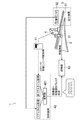
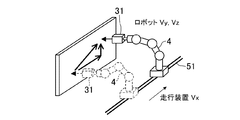
以下、探傷システムの実施形態を図面に基づいて説明する。尚、以下の好ましい実施形態の説明は、本質的に例示に過ぎない。図1は、探傷システムの全体構成を示している。この探傷システム1(以下、単にシステム1ともいう)は、ここでは、ワーク2に対して超音波を送信すると共に、その反射波を受信することによって、ワーク2の内部欠陥等の有無を検査する超音波探傷システムとして構成されている。ここでワークとしては、特に限定されるものではないが、例えばCFRP(Carbon Fiber Reinforced Plastics)等の複合材料製の航空機部品等を例として挙げることができる。ここで、このシステム1の検査対象としてのワーク2は、三次元形状を有している(尚、図3等では、理解容易のために、ワーク2を三次元形状を有するようには図示していない)。またワーク2は、所定の方向(例えば図1における概ね左右方向)に延びる長尺形状を有していて、その長手方向に対して反っていたり、ねじれていたりすることで、三次元形状を有することになる。
Hereinafter, embodiments of a flaw detection system will be described with reference to the drawings. The following description of the preferred embodiment is merely exemplary in nature. FIG. 1 shows the overall configuration of the flaw detection system. Here, the flaw detection system 1 (hereinafter, also simply referred to as the system 1) transmits an ultrasonic wave to the
このシステム1は、前記ワーク2の探傷情報を取得する探触子31と、探触子31がその手首に取り付けられる多関節ロボット(ロボット)4と、ロボット4をワーク2の長手方向に沿うように往復移動させる走行装置5と、ロボット4に電気的に接続されて、ロボット4の動作制御を行うロボットコントローラ41と、ロボットコントローラ41に対して接続されて、後述するように、探触子31(その動作対象点)の位置情報を算出する、例えばパーソナルコンピュータからなる制御装置42と、前記探触子31及び制御装置42のそれぞれに接続されて、位置情報及び探傷情報を取得する探傷器43と、を備えて構成されている。
The
探触子31は、その詳細な図示は省略するが、ワーク2に対して超音波を送信する送信器と、ワーク2からの反射波を受信する受信器とを含んで構成され、その反射波に基づいて探傷情報を取得する超音波探触子である。探触子31は、ワーク2の表面に対して所定の角度となるように、ロボット4によってその向きを調節されながら、前記ロボット4及び走行装置5によって、ワークの表面を倣うようにその表面の全体に亘って順次走査される。尚、図示は省略するが、探触子31及びワーク2は、水槽内で、超音波の伝播媒質としての水に浸漬された状態にされ、この状態で探傷検査を実施する。
Although the detailed illustration of the
多関節ロボット4は、図1等に概略を示すように、垂直多関節ロボットであって、例えば4,5又は6軸に構成されている。ここで、この探傷システム1においては、後述するように、多関節ロボット4として汎用ロボットを用いることが可能である。ここで言う「汎用ロボット」は、位置情報の取得がリアルタイムに行い得ないロボットである。汎用ロボットの採用は、探傷システム1の構成を簡易にする上で有利であると共に、システム1の開発期間を短縮する上でも有利である。前述したように、多関節ロボット4の手首には、探触子31が取り付けられ、多関節ロボット4は、その作動領域内において、探触子31を自在に移動させることが可能である。尚、図示は省略するが、このロボット4は、その各軸にエンコーダを有しており、ロボット4は、各軸のエンコーダ値をロボットコントローラ41に出力する。
The
ロボットコントローラ41は、前記ロボット4から、各軸のエンコーダ値を取得しつつ、そのロボット4に対して制御信号を出力することにより、このロボット4を制御し、それによって前記探触子31を、予め設定した所定の軌跡で移動させる(より正確には、ロボット4と走行装置5との組み合わせによって、探触子31は予め設定した所定の軌跡で移動する)。ロボットコントローラ41はまた、前記の各軸のエンコーダ値を制御装置42に出力する。
The
ここで、制御装置42は、ロボット4の各軸のエンコーダ値をリアルタイムに取得することができない。その結果、後述するように、予め設定された当該システム1の動作周期で、ロボット4による探触子31の位置情報を取得しようとしても、取得ミスが起こり得ることになる。
Here, the
走行装置5は、ロボット4のベースを移動させるための走行レール(走行軸)51を有しており、この走行レール51は、長尺のワーク2と平行になるように配置され、それによってロボット4が、ワーク2の長手方向に沿って往復移動するようにされている。ここで、走行レール51は、図1,5に示すような一軸構成(X軸)、又は、図7に示すような互いに直交する二軸構成(X,Y軸)とされている。いずれの構成においても、走行レールに対して平行な方向についての、ワーク2の形状変化の最大変化率(以下、単に変化率という)が小さくなるように、走行レール51は配設されている。このことについての詳細は、後述する。
The traveling
走行装置5はまた、例えばリニアエンコーダや、ロータリエンコーダ等からなる位置センサ52を有しており、この位置センサ52は、走行レール51上のロボット4の位置を検出して、その情報を前記制御装置42に出力する。これにより制御装置42は、この位置センサ52の検出値をリアルタイムに取得することが可能であり、走行装置5によるロボット4の位置情報は、予め設定された当該システム1の動作周期で確実に取得することが可能である。
The traveling
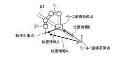
制御装置42は、前述したように、ロボットコントローラ41からの各軸のエンコーダ値を取得し、これに基づいて、その演算器421が、ロボット4による探触子31(つまり、探触子31が探触情報を取得している動作対象点)の位置情報を算出する。この位置情報は、ベース座標系(図2に示すように、ロボット4のベースに設定した座標系)から見た動作対象点の位置情報(位置情報C)である。制御装置42はまた、走行装置5の位置センサ52からの検出値を取得し、これに基づいて、その演算器421が、走行装置5によるロボット4の位置情報を算出する。この位置情報は、ワールド座標系(図2に示すように、地面に設定した座標系)から見たベース座標系の位置情報(位置情報B)に対応する。演算器421はさらに、位置情報B及び位置情報Cに基づいて、ワールド座標系から見た動作対象点の位置情報Aを算出する。こうして演算器421は、システム1の動作周期で位置情報Aを算出し、それによって、動作対象点の移動量を算出する。制御装置42は、動作対象点の移動量を、パルス信号として前記探傷器43に出力する。パルス信号は、1パルスが、動作対象点の所定の移動量に対応する。
As described above, the
探傷器43は、前述したように制御装置42に接続されており、この制御装置42からのパルス信号を取得する。探傷器43はまた、探触子31に接続されており、この探触子31からの探傷情報を取得する。より詳細に、探傷器43は、制御装置42からのパルス信号をトリガにして、探触子31からの探傷情報を取得する。具体的には、探傷情報を取得するワーク上での間隔が予め設定されていると共に、前述したように、1パルス当たりの動作対象点の移動量が定まっているため、探触子31は、設定された前記間隔に相当する数のパルス信号を受けたときに、探触子31からの探傷情報を取得する。このことによって探触子31の位置情報と探傷情報とを互いに対応付ける。例えば1パルスが、探触子31が1mm移動することに対応しているときに、10mm間隔でワーク2の探傷情報を取得すると設定されている場合は、探傷器43は、10パルス毎に、探触子31からの探傷情報を取得することになる。このように、探触子31の移動量に基づいて探触子31からの探傷情報を取得することにより、探触子31の位置情報と探傷情報との対応付けの処理を、別途行うようなことが不要になる。このことは、システムの簡略化の上で有利である。
The
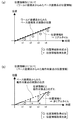
この探傷システム1においては、前述したように、ワーク2に対する探触子31の移動を、ロボット4及び走行装置5の組み合わせによって行うが、走行装置5から得られるロボット4の位置情報はリアルタイムに取得することができる一方で、ロボット4から得られる探触子31(以下、探触子31と動作対象点とは、ほぼ同義に用いる)の位置情報はリアルタイムに取得することができない。このようにリアルタイムに取得できないことによって、所望のタイミングで位置情報を取得しようとしても、取得ミスが生じ得ることになり、このことに起因して、取得(算出)した動作対象点の位置情報Aと、動作対象点の実際の位置との間にずれが生じる虞がある。このことについて図10を参照しながら説明する。図10(a)(b)はそれぞれ、横軸に時間を、縦軸に位置(制御装置42が算出した位置)を取ったグラフであり、t1,t2,t3,t4は、システム1の動作周期に対応する。走行装置5の位置センサ52に取得されたロボット4の位置情報Bは、リアルタイムに取得可能であって取得ミスが生じないため、ロボット4が等速移動をしているときには、その取得位置は時間に対して直線状になる(図10(a)参照)。これに対し、ロボット4から得られる探触子31の位置情報Cはリアルタイムに取得不可能であり、例えばt2,t3のように取得ミスが生じ得る(図10(b)参照)。このとき取得位置は、時間に対して折れ線状になる。つまり、位置情報を取得できないときには位置情報が更新されずに、前回値が保持されることになる。一方で、ベース座標系からみて動作対象点が等速に移動しているときには、図10(b)に破線で示すように、その動作対象点の位置は、実際には時間に対して直線状になることから、位置情報Cと、ベース座標系からみた動作対象点の実際の位置との間には、例えば図10(b)に矢印で示すだけの位置ずれ量が発生することになる。またこの位置ずれ量は、位置情報Bと位置情報Cから算出される位置情報Aにも当然生じることとなり、位置情報Aとワールド座標系からみた動作対象点との位置ずれ量となる。この位置ずれ量は、探傷器43において、動作対象点の位置情報と探傷情報とを対応付ける際に、実際の位置からずれた位置の探傷情報と対応付けることになるから、探傷検査の結果上では、ワークの内部欠陥の位置が、実際とは、ずれて示されることになり、探傷検査結果の位置精度を低下させる。
In the
そこで、この探傷システム1では、探傷検査結果の位置精度を向上させるべく、リアルタイムに位置情報を取得することができないロボット4による探触子31の移動動作をなるべく減らして、探触子31を、リアルタイムに位置情報の検出が可能な走行装置によって、極力、移動させるようにする。すなわち、探触子31のワーク2に対する走査は、主に走行装置5がロボット4を移動させることによって行い、ロボット4は、例えば探触子31の向きを、ワーク2の表面に沿うように変更したり、走行装置5によるロボット4の移動のみでは移動させることが不可能な場合に限って、探触子31を移動させたりする。このことを言い換えると、走行装置5の走行レール51を、ワーク2に沿うように配設するということができる。こうして、ロボット4による探触子31の移動を極力減らすことによって、位置情報の取得がリアルタイムに行えないことに起因する、位置情報のずれを抑制し、そのずれ量を、許容できるずれ量の範囲内に収めるようにする。この点について、図面を参照しながら、さらに詳細に説明する。
Therefore, in this
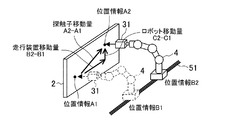
図3は、探触子31(動作対象点)の移動を定義している。すなわち、走行装置5によってロボット4が、位置情報B1から位置情報B2へと移動すると共に、ロボット4によって動作対象点が、位置情報C1から位置情報C2へと移動する結果、動作対象点が、ワーク2に対して位置情報A1から位置情報A2へと移動するとする。従って、探触子31(動作対象点)の移動量はA2−A1で示され、走行装置5の移動量はB2−B1で示され、ロボット4の移動量はC2−C1で示される。尚、図3では、理解容易のために、ワーク2が平板で、さらに図1とは異なり、当該ワーク2を起立した状態で描いている。
FIG. 3 defines the movement of the probe 31 (operation target point). That is, the
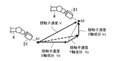
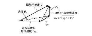
図4は、探触子31の移動により生じる速度Vを定義している。探触子31の移動速度Vは、X軸方向成分Vx、Y軸方向成分Vy、及びZ軸方向成分Vzによって表される。
FIG. 4 defines a velocity V generated by the movement of the
(走行装置が一軸構成の場合)
図5に示すように、ワーク2が概ねX軸方向に沿うように配置され、走行レール51がX軸方向に延びているとする。つまり、走行装置5が一軸構成とする。この場合、走行装置5が、探触子31の移動速度Vのうち、そのX軸方向成分Vx、を担い、ロボット4が、Y軸方向成分Vy及びZ軸方向成分Vzを担うことになる。
(When the traveling device has a single-axis configuration)
As shown in FIG. 5, it is assumed that the
先ず、ワーク2の、走行レール51に対する変化率r1は、数式(1−1)で示される。
First, the rate of change r 1 of the
ここで、θ1は、変化率r1が表す角度であり、Vrtは、ロボット4の動作速度である(図6参照)。Vrtはまた、数式(1−2)で表すことができる。 Here, θ 1 is an angle represented by the rate of change r 1 , and Vrt is an operation speed of the robot 4 (see FIG. 6). Vrt can also be expressed by Equation (1-2).
Vrtはさらに、θ1を用いて、数式(1−3)で表すことができる。 Vrt further using theta 1, it can be expressed by Equation (1-3).
![]()
![]()
ここで、前述したように、ロボット4による位置情報の取得が失敗したときには、そのロボット4による位置情報の取得が成功するまでの時間Tmax(システムの動作周期の上限)の間にロボット4の動作によって探触子31が移動するから、その時間Tmaxと、ロボット4の動作速度Vrtで表現されるずれ(Tmax×Vrt)が生じる。ここで設計者が許容できるずれ量をDとすると、数式(1−4)の関係が成立する。
Here, as described above, when the acquisition of the position information by the
数式(1−1)(1−3)(1−4)から、次の条件式(1−5)を導くことができる。 The following conditional expression (1-5) can be derived from Expressions (1-1), (1-3), and (1-4).
従って、この条件式(1−5)を満たすように、各変数V,r1,Tmax,Dを適宜設定すればよい。この内、探触子31の移動速度Vを低くすることによって、上限周期Tmaxは大きくし得る。このことは、システム1の動作周期を比較的長く設定することを可能にし、選定可能なロボットの自由度が大きくなることを意味する(位置情報の取得周期が比較的長いロボットも選定し得る)。逆に、上限周期Tmaxを大きく設定しつつも、システム1の動作周期を比較的短く設定した(それに伴い位置情報の取得周期が比較的短いロボットを選定した)ときには、仮にそのロボット4が位置情報の取得ミスを複数回繰り返したとしても、取得した位置情報と実際の位置とのずれ量が許容ずれ量Dに収まり得るため、そうした取得ミスに耐え得るシステムとなる。
Accordingly, the variables V, r 1 , Tmax, and D may be set as appropriate so as to satisfy this conditional expression (1-5). Of these, the upper limit cycle Tmax can be increased by lowering the moving speed V of the
一方で、探触子31の移動速度Vを低くすることは、ワーク2全体の走査に要する時間が長くなるため、一つのワーク2に対する検査時間は長くなってしまう不利益がある。探触子31の移動速度Vは、上限周期Tmax、及び、検査時間の双方の観点から適宜設定すればよい。
On the other hand, lowering the moving speed V of the
変化率r1は、走行装置5の走行レールの配置を適宜設定することによって小さくし得る。変化率r1をなるべく小さく設定することはまた、探触子31の移動を、極力、走行装置5によるものにして、ロボット4による探触子31の移動はなるべく行わないこと等価である。そうして、変化率r1をなるべく小さくすることが、上限周期Tmaxを大きくする上で有利になる。
The change rate r 1 can be reduced by appropriately setting the arrangement of the traveling rails of the traveling
許容ずれ量Dは、所望の設計値として適宜定められるものであるから、当該許容ずれ量Dを設定した上で、上限周期Tmaxを大きくするように、移動速度Vや変化率r1を設定することが望ましい。この内、移動速度Vは、前述したように、一つのワークの検査時間に関係することから、変化率r1をなるべく小さく設定することで、上限周期Tmaxを大きくことが特に好ましい。 Allowable displacement amount D is because those suitably determined as desired design value, upon setting the allowable displacement amount D, so as to increase the upper limit period Tmax, set the moving speed V and the rate of change r 1 It is desirable. Among these, since the moving speed V is related to the inspection time of one workpiece as described above, it is particularly preferable to increase the upper limit cycle Tmax by setting the rate of change r 1 as small as possible.
(2軸構成の場合)
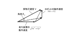
図7は、走行装置5の走行レール51が2軸構成の場合の図を示している。ここでは、走行レール51が、X軸及びY軸のそれぞれに対応しているとする。この場合は、走行装置5が移動速度のX軸方向成分Vx及びY軸方向成分Vyを担い、Z軸方向成分Vzはロボット4が担うことになる。
(For 2-axis configuration)
FIG. 7 shows a diagram when the traveling
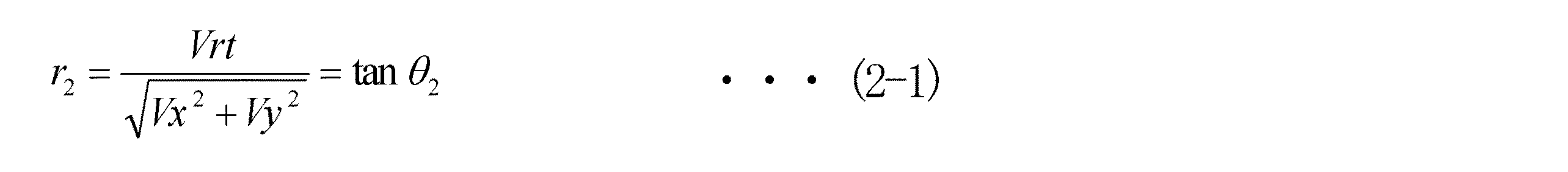
この構成において、ワーク2の、走行レール51に対する変化率r2は、数式(2−1)で表される。
In this configuration, the rate of change r 2 of the
ここで、図8に示すように、θ2は変化率r2が表す角度である。ロボット動作速度Vrtは、数式(2−2)で表される。 Here, as shown in FIG. 8, θ 2 is an angle represented by the rate of change r 2 . The robot operation speed Vrt is expressed by Expression (2-2).
またVrtは、前記と同様に、θ2を用いて数式(2−3)のように表される。 Further Vrt is similar to the above is expressed as equation (2-3) using the theta 2.
前述のように、ロボット4による位置情報の取得に失敗したときには、その上限周期Tmaxとロボット4による移動速度とに基づくずれが生じることから、許容できるずれ量をDとしたときに、数式(2−4)の関係が成立する。
As described above, when the acquisition of the position information by the
よって、数式(2−1)(2−3)(2−4)に基づいて、次の条件式(2−5)が導かれる。 Therefore, the following conditional expression (2-5) is derived based on Expressions (2-1), (2-3), and (2-4).
従って、走行装置5が二軸構成であるときには、この条件式(2−5)を満たすように、各変数V,r2,Tmax,Dを適宜設定すればよい。
Therefore, when the traveling
以上の検討から、条件式は以下の数式(1)のように表記することができる。 From the above examination, the conditional expression can be expressed as the following Expression (1).
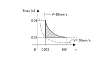
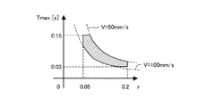
ここで、走行装置5が一軸構成の場合に、具体的な数値を挙げて検討する。許容ずれ量Dを0.5mm、探触子31の移動速度を50mm/sにし、変化率rを1/10となるように走行装置5の走行レール51を設定する。このときに、上限周期Tmaxは、条件式(1)より、おおよそ0.10s(尚、ここでの「s」は秒(sec)である)以下となる。従って、ロボット4としては、この0.1s以内に、位置情報を取得し得る能力を有するロボット4を選定すればよい。これは、汎用ロボットで十分に対応可能である。また、このケースにおいて、システムの動作周期を5msに設定すれば、20回の取得ミスにも耐え得るシステムとなる。尚、実用上では、システム1の上限周期に余裕を持たせることが好ましい(例えば前記の0.1sのときには、10msや、20ms等)。ここで、前記の条件式に従って、探触子31の移動速度V、上限周期Tmax及び変化率rのとり得る範囲の一例について説明する。例えば図11に範囲を示すように、探触子31の移動速度Vは、50〜100mm/s程度に設定すればよく、上限周期Tmaxは、0.02〜0.04s程度に設定すればよく、変化率rは、0.005〜0.01程度に設定すればよい。こうすることによって、許容ずれ量Dは、0.01mm程度に設定することが可能になる。またこれとは別の例として、図12に示す範囲を満たすように、探触子31の移動速度Vは、50〜100mm/s程度に設定すればよく、上限周期Tmaxは、0.03〜0.15s程度に設定すればよく、変化率rは、0.05〜0.2程度に設定すればよい。こうすることによって、許容ずれ量Dは、0.5mm程度に設定することが可能になる。
Here, when the traveling
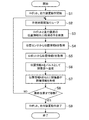
最後に、この探傷システム1の動作フローについて、図9を参照しながら説明する。先ず、ステップS1でロボット4及び走行装置5の動作が開始されれば、以下の各ステップを、所定の時間間隔、つまり、予め設定されたシステム1の動作周期でループする(ステップS2)。
Finally, the operation flow of the
ステップS3では、ロボット4と走行装置5とのそれぞれの位置情報(位置情報B及び位置情報C)の取得命令を発信し、ステップS4で、走行装置5の位置センサ52から位置情報Bを取得する。続くステップS5では、ロボット4から位置情報Cを取得し、制御装置42は、ステップS6で、位置情報B及び位置情報Cに基づいて、位置情報Aを算出し、それをパルス信号として探傷器43に出力する(前述したように、探触子31の移動量をパルス信号として出力する)。探傷器43は、位置情報Aに基づいて探触子31から探傷情報を取得することで、位置情報A、つまり動作対象点の位置情報と探傷情報とを対応付ける(ステップS7)。ステップS8では、ワーク2における、探触子31の走査の最終位置まで移動したか否かを判定し、最終位置まで移動していない、つまり未だワーク2の検査が完了していないNOのときにはステップS2に戻って、前記ステップS3〜7を繰り返す。一方、ステップS8で最終位置まで移動した、つまりワーク2の検査が完了したYESのときにはステップS9に移行して、ロボット4及び走行装置5の動作を終了する。
In step S3, the acquisition command of each positional information (position information B and positional information C) of the
以上説明したように、この探傷システム1では、ロボット4と走行装置5とを組み合わせて探触子31を移動させ、それによって、三次元形状を有するワーク2の探傷検査を実現しており、その際に、前述した条件式(1)を満たすように、各変数V,r,Tmax,Dを設定している。
As described above, in this
特にこのシステム1では、走行装置5の走行レール51の配置を適切にすることによって、変化率rを小さくすることにより、走行装置5によって探触子31を移動させる割合を多くし、ロボット4によって探触子31を移動させる割合を少なくしている。このことにより、ロボット4による動作対象点(探触子31)の位置情報は、リアルタイムに取得することができないものの、それに起因する実際の位置情報とのずれ量を小さくして、許容範囲に収めることが可能になる。つまり、この探傷システム1では、探傷結果における位置精度が向上し得る。
In particular, in this
しかも、このシステム1では、位置情報をリアルタイムに取得可能なロボット4は不要であり、ロボット4としては汎用の多関節ロボットを採用することが可能である。このことは、探傷システム1の構築に要するコストの低減化、及び、その開発に要する時間を短縮する点で有利である。
In addition, in this
尚、この実施形態では、パルス信号として出力される、探触子31の移動量に基づいて、探傷情報を取得し、これによって、探触子31の位置情報と探傷情報とを対応付けているが、例えば所定のタイミング信号に基づいて、探触子31の位置情報と探傷情報とを取得して、これらを対応付けるようにしてもよい。
In this embodiment, the flaw detection information is acquired based on the movement amount of the
また、前記の実施形態では、探傷システム1を、超音波探触子31を備えた超音波探傷システム1としているが、これに限定されず、ワーク2の探傷情報を取得するプローブを、多関節ロボット4の手首に取り付けたシステムであれば、種々のシステムに対して、ここに開示した技術を適用することが可能である。
In the above-described embodiment, the
以上説明したように、ここに開示した探傷システムは、三次元形状を有するワークの探傷検査を、簡易なシステム構成で、精度良く行い得る点で有用である。 As described above, the flaw detection system disclosed herein is useful in that flaw detection inspection of a workpiece having a three-dimensional shape can be performed with high accuracy with a simple system configuration.
1 探傷システム
2 ワーク
31 探触子(プローブ)
4 多関節ロボット
41 ロボットコントローラ(ロボット位置情報取得器)
42 制御装置(制御器)
43 探傷器
5 走行装置
51 走行レール(走行軸)
52 位置センサ(走行装置位置情報取得器)
1
4 Articulated
42 Control device
43
52 Position sensor (travel device position information acquisition device)
Claims (2)
多関節ロボットと、
所定の一軸又は二軸からなる走行軸上で前記多関節ロボットを移動させることにより、前記多関節ロボットを前記ワークに沿うように移動させる走行装置と、
前記多関節ロボットの手首に取り付けられかつ、当該多関節ロボット及び前記走行装置の組み合わせにより前記ワークの表面を走査しながら、当該ワークの探傷情報を取得するプローブと、
前記走行装置によって前記走行軸上を移動する多関節ロボットの位置に関する情報をリアルタイムに取得して出力する取得器であって、当該多関節ロボットの位置に関する情報を、所定の動作周期で出力する走行装置位置情報取得器と、
前記多関節ロボットによって移動される前記プローブの位置に関する情報を非リアルタイムに取得して出力する取得器であって、当該プローブの位置に関する情報を、前記動作周期で出力するロボット位置情報取得器と、
前記走行装置位置情報取得器からの情報を受けて、前記多関節ロボットの位置をワールド座標系からみたベース座標系の位置情報(第1位置情報)として算出すると共に、前記ロボット位置情報取得器からの情報を受けて、前記プローブの位置をベース座標系からみたプローブの位置情報(第2位置情報)として算出し、さらに、前記第1及び第2位置情報に基づいて、ワールド座標系からみた前記プローブの位置情報(第3位置情報)を算出して、これを出力する制御器と、
前記制御器から第3位置情報を取得すると共に、前記プローブから前記探傷情報を取得して、前記プローブの位置情報と前記探傷情報とを対応付ける探傷器と、を備え、
前記第3位置情報と、前記プローブの実際の位置との間の許容できるずれ量をDとしたときに、条件式(1)を満たすように、前記の許容ずれ量D、前記動作周期の上限Tmax、前記走行装置及び多関節ロボットによる前記プローブの移動速度V、及び、前記ワークの形状の前記走行軸に対する変化率r、をそれぞれ設定する探傷システム。
With articulated robots,
A traveling device that moves the multi-joint robot along the workpiece by moving the multi-joint robot on a predetermined one-axis or two-axis travel axis;
A probe attached to the wrist of the articulated robot and acquiring flaw detection information of the work while scanning the surface of the work by a combination of the articulated robot and the traveling device;
A travel device that obtains and outputs in real time information related to the position of the articulated robot that moves on the travel axis by the travel device, and outputs information related to the position of the articulated robot in a predetermined operation cycle. A device location information acquirer;
An acquisition unit that acquires and outputs information on the position of the probe moved by the articulated robot in non-real time, and a robot position information acquisition unit that outputs information on the position of the probe in the operation cycle;
In response to information from the travel device position information acquisition unit, the position of the articulated robot is calculated as position information (first position information) of a base coordinate system viewed from the world coordinate system, and from the robot position information acquisition unit The position of the probe is calculated as position information (second position information) of the probe viewed from the base coordinate system, and further, the position of the probe viewed from the world coordinate system is calculated based on the first and second position information. A controller that calculates position information (third position information) of the probe and outputs the position information;
The third position information is acquired from the controller, the flaw detection information is acquired from the probe, and a flaw detector that associates the position information of the probe with the flaw detection information,
When the allowable deviation amount between the third position information and the actual position of the probe is D, the allowable deviation amount D and the upper limit of the operation cycle so as to satisfy the conditional expression (1) A flaw detection system that sets Tmax, the moving speed V of the probe by the traveling device and the articulated robot, and the rate of change r of the shape of the workpiece with respect to the traveling axis.
前記制御器は、前記第3位置情報から算出した前記プローブの移動量を、パルス信号として出力し、
前記探傷器は、前記制御器からのパルス信号をトリガにして、前記プローブから探傷情報を取得することにより、前記プローブの位置情報と前記探傷情報とを対応付ける探傷システム。 The flaw detection system according to claim 1,
The controller outputs a movement amount of the probe calculated from the third position information as a pulse signal;
The flaw detector is a flaw detection system that associates position information of the probe with the flaw detection information by acquiring flaw detection information from the probe with a pulse signal from the controller as a trigger.
Priority Applications (1)
| Application Number | Priority Date | Filing Date | Title |
|---|---|---|---|
| JP2009260744A JP5427002B2 (en) | 2009-11-16 | 2009-11-16 | Flaw detection system |
Applications Claiming Priority (1)
| Application Number | Priority Date | Filing Date | Title |
|---|---|---|---|
| JP2009260744A JP5427002B2 (en) | 2009-11-16 | 2009-11-16 | Flaw detection system |
Publications (2)
| Publication Number | Publication Date |
|---|---|
| JP2011106905A true JP2011106905A (en) | 2011-06-02 |
| JP5427002B2 JP5427002B2 (en) | 2014-02-26 |
Family
ID=44230555
Family Applications (1)
| Application Number | Title | Priority Date | Filing Date |
|---|---|---|---|
| JP2009260744A Active JP5427002B2 (en) | 2009-11-16 | 2009-11-16 | Flaw detection system |
Country Status (1)
| Country | Link |
|---|---|
| JP (1) | JP5427002B2 (en) |
Cited By (1)
| Publication number | Priority date | Publication date | Assignee | Title |
|---|---|---|---|---|
| CN112539702A (en) * | 2020-12-29 | 2021-03-23 | 上海市东方海事工程技术有限公司 | Automatic centering method and system for rail flaw detection vehicle |
Citations (5)
| Publication number | Priority date | Publication date | Assignee | Title |
|---|---|---|---|---|
| JPS63135814A (en) * | 1986-11-28 | 1988-06-08 | Hitachi Constr Mach Co Ltd | Apparatus for controlling posture of probe |
| JPH03123857A (en) * | 1989-10-09 | 1991-05-27 | Hitachi Constr Mach Co Ltd | Speed controller for probe |
| JPH08110332A (en) * | 1994-10-11 | 1996-04-30 | Komatsu Ltd | Ultrasonic inspection method by articulated robot and its apparatus |
| JPH1014915A (en) * | 1996-07-01 | 1998-01-20 | Aloka Co Ltd | Mechanical scanning type ultrasonograph |
| JPH1114610A (en) * | 1997-06-18 | 1999-01-22 | Chiyoda Kogyo Kk | Ultrasonic flaw detection method by robot |
-
2009
- 2009-11-16 JP JP2009260744A patent/JP5427002B2/en active Active
Patent Citations (5)
| Publication number | Priority date | Publication date | Assignee | Title |
|---|---|---|---|---|
| JPS63135814A (en) * | 1986-11-28 | 1988-06-08 | Hitachi Constr Mach Co Ltd | Apparatus for controlling posture of probe |
| JPH03123857A (en) * | 1989-10-09 | 1991-05-27 | Hitachi Constr Mach Co Ltd | Speed controller for probe |
| JPH08110332A (en) * | 1994-10-11 | 1996-04-30 | Komatsu Ltd | Ultrasonic inspection method by articulated robot and its apparatus |
| JPH1014915A (en) * | 1996-07-01 | 1998-01-20 | Aloka Co Ltd | Mechanical scanning type ultrasonograph |
| JPH1114610A (en) * | 1997-06-18 | 1999-01-22 | Chiyoda Kogyo Kk | Ultrasonic flaw detection method by robot |
Cited By (1)
| Publication number | Priority date | Publication date | Assignee | Title |
|---|---|---|---|---|
| CN112539702A (en) * | 2020-12-29 | 2021-03-23 | 上海市东方海事工程技术有限公司 | Automatic centering method and system for rail flaw detection vehicle |
Also Published As
| Publication number | Publication date |
|---|---|
| JP5427002B2 (en) | 2014-02-26 |
Similar Documents
| Publication | Publication Date | Title |
|---|---|---|
| Mineo et al. | Robotic path planning for non-destructive testing–A custom MATLAB toolbox approach | |
| US20150177194A1 (en) | Dual Robot Detection Apparatus For Non-Damage Detection | |
| KR102226986B1 (en) | Automatic apparatus and position detecting apparatus | |
| US8429973B2 (en) | Ultrasonic inspection device and ultrasonic inspection method | |
| US9774827B2 (en) | Imaging inspection apparatus for setting one or more image-capturing positions on a line that connects two taught positions, control device thereof, and method of controlling imaging inspection apparatus | |
| EP3799790B1 (en) | Method for tracking location of two-dimensional non-destructive inspection scanner on target object using scanned structural features | |
| US9651525B2 (en) | Method and apparatus for scanning an object | |
| CN104502456A (en) | Single-manipulator ultrasonic non-destructive testing device and single-manipulator ultrasonic non-destructive testing method | |
| CN110196231B (en) | A laser ultrasonic offline detection device and method for additive parts | |
| CN104597125A (en) | Ultrasonic detection control method and ultrasonic detection control device for 3D printed piece | |
| CN110081821A (en) | Intelligent high-speed rail white body assembling quality detection device and its method | |
| JP2009264956A (en) | Three-dimensional shape-position quality evaluation system and its method | |
| EP4071467B1 (en) | Ultrasound inspection system and method | |
| JP5427002B2 (en) | Flaw detection system | |
| EP3869190A1 (en) | Method for ultrasonic inspection of structure having radiused surface using multi-centric radius focusing | |
| CA2526835C (en) | Method and device for testing a structural component having a complex surface contour, by means of ultrasound | |
| CN102253125A (en) | Automatic adjustment device for position and attitude of ultrasonic detection transducer | |
| Louviot et al. | Robotised UT transmission NDT of composite complex shaped parts | |
| US10955237B2 (en) | Measurement method and measurement apparatus for capturing the surface topology of a workpiece | |
| CN102590246A (en) | Camera-shooting scanning positioning device of X-ray digital flat panel imaging detecting system | |
| KR101069891B1 (en) | Controller for curved plate rounding processing apparatus and control method thereof | |
| JP5629883B2 (en) | Shape measuring apparatus, shape measuring method, and shape measuring program | |
| KR101686825B1 (en) | Control device for 3d scanner | |
| Brown et al. | Automated full matrix capture for industrial processes | |
| Biro et al. | Integration of a scanning interferometer into a robotic inspection system for factory deployment |
Legal Events
| Date | Code | Title | Description |
|---|---|---|---|
| RD02 | Notification of acceptance of power of attorney |
Free format text: JAPANESE INTERMEDIATE CODE: A7422 Effective date: 20120131 |
|
| A621 | Written request for application examination |
Free format text: JAPANESE INTERMEDIATE CODE: A621 Effective date: 20120418 |
|
| A977 | Report on retrieval |
Free format text: JAPANESE INTERMEDIATE CODE: A971007 Effective date: 20130621 |
|
| TRDD | Decision of grant or rejection written | ||
| A01 | Written decision to grant a patent or to grant a registration (utility model) |
Free format text: JAPANESE INTERMEDIATE CODE: A01 Effective date: 20131112 |
|
| A61 | First payment of annual fees (during grant procedure) |
Free format text: JAPANESE INTERMEDIATE CODE: A61 Effective date: 20131129 |
|
| R150 | Certificate of patent or registration of utility model |
Free format text: JAPANESE INTERMEDIATE CODE: R150 Ref document number: 5427002 Country of ref document: JP Free format text: JAPANESE INTERMEDIATE CODE: R150 |
|
| R250 | Receipt of annual fees |
Free format text: JAPANESE INTERMEDIATE CODE: R250 |
|
| R250 | Receipt of annual fees |
Free format text: JAPANESE INTERMEDIATE CODE: R250 |
|
| R250 | Receipt of annual fees |
Free format text: JAPANESE INTERMEDIATE CODE: R250 |
|
| R250 | Receipt of annual fees |
Free format text: JAPANESE INTERMEDIATE CODE: R250 |
|
| R250 | Receipt of annual fees |
Free format text: JAPANESE INTERMEDIATE CODE: R250 |
|
| R250 | Receipt of annual fees |
Free format text: JAPANESE INTERMEDIATE CODE: R250 |
|
| R250 | Receipt of annual fees |
Free format text: JAPANESE INTERMEDIATE CODE: R250 |
|
| R250 | Receipt of annual fees |
Free format text: JAPANESE INTERMEDIATE CODE: R250 |
|
| R250 | Receipt of annual fees |
Free format text: JAPANESE INTERMEDIATE CODE: R250 |
|
| R250 | Receipt of annual fees |
Free format text: JAPANESE INTERMEDIATE CODE: R250 |