JP2011106295A - Thermoelectric hydrogen supply system - Google Patents
Thermoelectric hydrogen supply system Download PDFInfo
- Publication number
- JP2011106295A JP2011106295A JP2009259349A JP2009259349A JP2011106295A JP 2011106295 A JP2011106295 A JP 2011106295A JP 2009259349 A JP2009259349 A JP 2009259349A JP 2009259349 A JP2009259349 A JP 2009259349A JP 2011106295 A JP2011106295 A JP 2011106295A
- Authority
- JP
- Japan
- Prior art keywords
- gas
- hydrogen
- steam
- lng
- steam reformer
- Prior art date
- Legal status (The legal status is an assumption and is not a legal conclusion. Google has not performed a legal analysis and makes no representation as to the accuracy of the status listed.)
- Granted
Links
Images

Classifications
-
- F—MECHANICAL ENGINEERING; LIGHTING; HEATING; WEAPONS; BLASTING
- F25—REFRIGERATION OR COOLING; COMBINED HEATING AND REFRIGERATION SYSTEMS; HEAT PUMP SYSTEMS; MANUFACTURE OR STORAGE OF ICE; LIQUEFACTION SOLIDIFICATION OF GASES
- F25J—LIQUEFACTION, SOLIDIFICATION OR SEPARATION OF GASES OR GASEOUS OR LIQUEFIED GASEOUS MIXTURES BY PRESSURE AND COLD TREATMENT OR BY BRINGING THEM INTO THE SUPERCRITICAL STATE
- F25J3/00—Processes or apparatus for separating the constituents of gaseous or liquefied gaseous mixtures involving the use of liquefaction or solidification
- F25J3/06—Processes or apparatus for separating the constituents of gaseous or liquefied gaseous mixtures involving the use of liquefaction or solidification by partial condensation
- F25J3/0605—Processes or apparatus for separating the constituents of gaseous or liquefied gaseous mixtures involving the use of liquefaction or solidification by partial condensation characterised by the feed stream
- F25J3/0625—H2/CO mixtures, i.e. synthesis gas; Water gas or shifted synthesis gas
-
- F—MECHANICAL ENGINEERING; LIGHTING; HEATING; WEAPONS; BLASTING
- F25—REFRIGERATION OR COOLING; COMBINED HEATING AND REFRIGERATION SYSTEMS; HEAT PUMP SYSTEMS; MANUFACTURE OR STORAGE OF ICE; LIQUEFACTION SOLIDIFICATION OF GASES
- F25J—LIQUEFACTION, SOLIDIFICATION OR SEPARATION OF GASES OR GASEOUS OR LIQUEFIED GASEOUS MIXTURES BY PRESSURE AND COLD TREATMENT OR BY BRINGING THEM INTO THE SUPERCRITICAL STATE
- F25J3/00—Processes or apparatus for separating the constituents of gaseous or liquefied gaseous mixtures involving the use of liquefaction or solidification
- F25J3/02—Processes or apparatus for separating the constituents of gaseous or liquefied gaseous mixtures involving the use of liquefaction or solidification by rectification, i.e. by continuous interchange of heat and material between a vapour stream and a liquid stream
- F25J3/0204—Processes or apparatus for separating the constituents of gaseous or liquefied gaseous mixtures involving the use of liquefaction or solidification by rectification, i.e. by continuous interchange of heat and material between a vapour stream and a liquid stream characterised by the feed stream
- F25J3/0223—H2/CO mixtures, i.e. synthesis gas; Water gas or shifted synthesis gas
-
- F—MECHANICAL ENGINEERING; LIGHTING; HEATING; WEAPONS; BLASTING
- F25—REFRIGERATION OR COOLING; COMBINED HEATING AND REFRIGERATION SYSTEMS; HEAT PUMP SYSTEMS; MANUFACTURE OR STORAGE OF ICE; LIQUEFACTION SOLIDIFICATION OF GASES
- F25J—LIQUEFACTION, SOLIDIFICATION OR SEPARATION OF GASES OR GASEOUS OR LIQUEFIED GASEOUS MIXTURES BY PRESSURE AND COLD TREATMENT OR BY BRINGING THEM INTO THE SUPERCRITICAL STATE
- F25J3/00—Processes or apparatus for separating the constituents of gaseous or liquefied gaseous mixtures involving the use of liquefaction or solidification
- F25J3/02—Processes or apparatus for separating the constituents of gaseous or liquefied gaseous mixtures involving the use of liquefaction or solidification by rectification, i.e. by continuous interchange of heat and material between a vapour stream and a liquid stream
- F25J3/0228—Processes or apparatus for separating the constituents of gaseous or liquefied gaseous mixtures involving the use of liquefaction or solidification by rectification, i.e. by continuous interchange of heat and material between a vapour stream and a liquid stream characterised by the separated product stream
- F25J3/0252—Processes or apparatus for separating the constituents of gaseous or liquefied gaseous mixtures involving the use of liquefaction or solidification by rectification, i.e. by continuous interchange of heat and material between a vapour stream and a liquid stream characterised by the separated product stream separation of hydrogen
-
- F—MECHANICAL ENGINEERING; LIGHTING; HEATING; WEAPONS; BLASTING
- F25—REFRIGERATION OR COOLING; COMBINED HEATING AND REFRIGERATION SYSTEMS; HEAT PUMP SYSTEMS; MANUFACTURE OR STORAGE OF ICE; LIQUEFACTION SOLIDIFICATION OF GASES
- F25J—LIQUEFACTION, SOLIDIFICATION OR SEPARATION OF GASES OR GASEOUS OR LIQUEFIED GASEOUS MIXTURES BY PRESSURE AND COLD TREATMENT OR BY BRINGING THEM INTO THE SUPERCRITICAL STATE
- F25J3/00—Processes or apparatus for separating the constituents of gaseous or liquefied gaseous mixtures involving the use of liquefaction or solidification
- F25J3/02—Processes or apparatus for separating the constituents of gaseous or liquefied gaseous mixtures involving the use of liquefaction or solidification by rectification, i.e. by continuous interchange of heat and material between a vapour stream and a liquid stream
- F25J3/0228—Processes or apparatus for separating the constituents of gaseous or liquefied gaseous mixtures involving the use of liquefaction or solidification by rectification, i.e. by continuous interchange of heat and material between a vapour stream and a liquid stream characterised by the separated product stream
- F25J3/0266—Processes or apparatus for separating the constituents of gaseous or liquefied gaseous mixtures involving the use of liquefaction or solidification by rectification, i.e. by continuous interchange of heat and material between a vapour stream and a liquid stream characterised by the separated product stream separation of carbon dioxide
-
- F—MECHANICAL ENGINEERING; LIGHTING; HEATING; WEAPONS; BLASTING
- F25—REFRIGERATION OR COOLING; COMBINED HEATING AND REFRIGERATION SYSTEMS; HEAT PUMP SYSTEMS; MANUFACTURE OR STORAGE OF ICE; LIQUEFACTION SOLIDIFICATION OF GASES
- F25J—LIQUEFACTION, SOLIDIFICATION OR SEPARATION OF GASES OR GASEOUS OR LIQUEFIED GASEOUS MIXTURES BY PRESSURE AND COLD TREATMENT OR BY BRINGING THEM INTO THE SUPERCRITICAL STATE
- F25J3/00—Processes or apparatus for separating the constituents of gaseous or liquefied gaseous mixtures involving the use of liquefaction or solidification
- F25J3/02—Processes or apparatus for separating the constituents of gaseous or liquefied gaseous mixtures involving the use of liquefaction or solidification by rectification, i.e. by continuous interchange of heat and material between a vapour stream and a liquid stream
- F25J3/0228—Processes or apparatus for separating the constituents of gaseous or liquefied gaseous mixtures involving the use of liquefaction or solidification by rectification, i.e. by continuous interchange of heat and material between a vapour stream and a liquid stream characterised by the separated product stream
- F25J3/0271—Processes or apparatus for separating the constituents of gaseous or liquefied gaseous mixtures involving the use of liquefaction or solidification by rectification, i.e. by continuous interchange of heat and material between a vapour stream and a liquid stream characterised by the separated product stream separation of H2/CO mixtures, i.e. of synthesis gas
-
- F—MECHANICAL ENGINEERING; LIGHTING; HEATING; WEAPONS; BLASTING
- F25—REFRIGERATION OR COOLING; COMBINED HEATING AND REFRIGERATION SYSTEMS; HEAT PUMP SYSTEMS; MANUFACTURE OR STORAGE OF ICE; LIQUEFACTION SOLIDIFICATION OF GASES
- F25J—LIQUEFACTION, SOLIDIFICATION OR SEPARATION OF GASES OR GASEOUS OR LIQUEFIED GASEOUS MIXTURES BY PRESSURE AND COLD TREATMENT OR BY BRINGING THEM INTO THE SUPERCRITICAL STATE
- F25J3/00—Processes or apparatus for separating the constituents of gaseous or liquefied gaseous mixtures involving the use of liquefaction or solidification
- F25J3/06—Processes or apparatus for separating the constituents of gaseous or liquefied gaseous mixtures involving the use of liquefaction or solidification by partial condensation
- F25J3/063—Processes or apparatus for separating the constituents of gaseous or liquefied gaseous mixtures involving the use of liquefaction or solidification by partial condensation characterised by the separated product stream
- F25J3/0655—Processes or apparatus for separating the constituents of gaseous or liquefied gaseous mixtures involving the use of liquefaction or solidification by partial condensation characterised by the separated product stream separation of hydrogen
-
- F—MECHANICAL ENGINEERING; LIGHTING; HEATING; WEAPONS; BLASTING
- F25—REFRIGERATION OR COOLING; COMBINED HEATING AND REFRIGERATION SYSTEMS; HEAT PUMP SYSTEMS; MANUFACTURE OR STORAGE OF ICE; LIQUEFACTION SOLIDIFICATION OF GASES
- F25J—LIQUEFACTION, SOLIDIFICATION OR SEPARATION OF GASES OR GASEOUS OR LIQUEFIED GASEOUS MIXTURES BY PRESSURE AND COLD TREATMENT OR BY BRINGING THEM INTO THE SUPERCRITICAL STATE
- F25J3/00—Processes or apparatus for separating the constituents of gaseous or liquefied gaseous mixtures involving the use of liquefaction or solidification
- F25J3/06—Processes or apparatus for separating the constituents of gaseous or liquefied gaseous mixtures involving the use of liquefaction or solidification by partial condensation
- F25J3/063—Processes or apparatus for separating the constituents of gaseous or liquefied gaseous mixtures involving the use of liquefaction or solidification by partial condensation characterised by the separated product stream
- F25J3/067—Processes or apparatus for separating the constituents of gaseous or liquefied gaseous mixtures involving the use of liquefaction or solidification by partial condensation characterised by the separated product stream separation of carbon dioxide
-
- F—MECHANICAL ENGINEERING; LIGHTING; HEATING; WEAPONS; BLASTING
- F25—REFRIGERATION OR COOLING; COMBINED HEATING AND REFRIGERATION SYSTEMS; HEAT PUMP SYSTEMS; MANUFACTURE OR STORAGE OF ICE; LIQUEFACTION SOLIDIFICATION OF GASES
- F25J—LIQUEFACTION, SOLIDIFICATION OR SEPARATION OF GASES OR GASEOUS OR LIQUEFIED GASEOUS MIXTURES BY PRESSURE AND COLD TREATMENT OR BY BRINGING THEM INTO THE SUPERCRITICAL STATE
- F25J2210/00—Processes characterised by the type or other details of the feed stream
- F25J2210/62—Liquefied natural gas [LNG]; Natural gas liquids [NGL]; Liquefied petroleum gas [LPG]
-
- F—MECHANICAL ENGINEERING; LIGHTING; HEATING; WEAPONS; BLASTING
- F25—REFRIGERATION OR COOLING; COMBINED HEATING AND REFRIGERATION SYSTEMS; HEAT PUMP SYSTEMS; MANUFACTURE OR STORAGE OF ICE; LIQUEFACTION SOLIDIFICATION OF GASES
- F25J—LIQUEFACTION, SOLIDIFICATION OR SEPARATION OF GASES OR GASEOUS OR LIQUEFIED GASEOUS MIXTURES BY PRESSURE AND COLD TREATMENT OR BY BRINGING THEM INTO THE SUPERCRITICAL STATE
- F25J2215/00—Processes characterised by the type or other details of the product stream
- F25J2215/04—Recovery of liquid products
-
- F—MECHANICAL ENGINEERING; LIGHTING; HEATING; WEAPONS; BLASTING
- F25—REFRIGERATION OR COOLING; COMBINED HEATING AND REFRIGERATION SYSTEMS; HEAT PUMP SYSTEMS; MANUFACTURE OR STORAGE OF ICE; LIQUEFACTION SOLIDIFICATION OF GASES
- F25J—LIQUEFACTION, SOLIDIFICATION OR SEPARATION OF GASES OR GASEOUS OR LIQUEFIED GASEOUS MIXTURES BY PRESSURE AND COLD TREATMENT OR BY BRINGING THEM INTO THE SUPERCRITICAL STATE
- F25J2230/00—Processes or apparatus involving steps for increasing the pressure of gaseous process streams
- F25J2230/30—Compression of the feed stream
-
- F—MECHANICAL ENGINEERING; LIGHTING; HEATING; WEAPONS; BLASTING
- F25—REFRIGERATION OR COOLING; COMBINED HEATING AND REFRIGERATION SYSTEMS; HEAT PUMP SYSTEMS; MANUFACTURE OR STORAGE OF ICE; LIQUEFACTION SOLIDIFICATION OF GASES
- F25J—LIQUEFACTION, SOLIDIFICATION OR SEPARATION OF GASES OR GASEOUS OR LIQUEFIED GASEOUS MIXTURES BY PRESSURE AND COLD TREATMENT OR BY BRINGING THEM INTO THE SUPERCRITICAL STATE
- F25J2270/00—Refrigeration techniques used
- F25J2270/90—External refrigeration, e.g. conventional closed-loop mechanical refrigeration unit using Freon or NH3, unspecified external refrigeration
- F25J2270/904—External refrigeration, e.g. conventional closed-loop mechanical refrigeration unit using Freon or NH3, unspecified external refrigeration by liquid or gaseous cryogen in an open loop
-
- Y—GENERAL TAGGING OF NEW TECHNOLOGICAL DEVELOPMENTS; GENERAL TAGGING OF CROSS-SECTIONAL TECHNOLOGIES SPANNING OVER SEVERAL SECTIONS OF THE IPC; TECHNICAL SUBJECTS COVERED BY FORMER USPC CROSS-REFERENCE ART COLLECTIONS [XRACs] AND DIGESTS
- Y02—TECHNOLOGIES OR APPLICATIONS FOR MITIGATION OR ADAPTATION AGAINST CLIMATE CHANGE
- Y02C—CAPTURE, STORAGE, SEQUESTRATION OR DISPOSAL OF GREENHOUSE GASES [GHG]
- Y02C20/00—Capture or disposal of greenhouse gases
- Y02C20/40—Capture or disposal of greenhouse gases of CO2
-
- Y—GENERAL TAGGING OF NEW TECHNOLOGICAL DEVELOPMENTS; GENERAL TAGGING OF CROSS-SECTIONAL TECHNOLOGIES SPANNING OVER SEVERAL SECTIONS OF THE IPC; TECHNICAL SUBJECTS COVERED BY FORMER USPC CROSS-REFERENCE ART COLLECTIONS [XRACs] AND DIGESTS
- Y02—TECHNOLOGIES OR APPLICATIONS FOR MITIGATION OR ADAPTATION AGAINST CLIMATE CHANGE
- Y02E—REDUCTION OF GREENHOUSE GAS [GHG] EMISSIONS, RELATED TO ENERGY GENERATION, TRANSMISSION OR DISTRIBUTION
- Y02E20/00—Combustion technologies with mitigation potential
- Y02E20/14—Combined heat and power generation [CHP]
Landscapes
- Engineering & Computer Science (AREA)
- Physics & Mathematics (AREA)
- Mechanical Engineering (AREA)
- Thermal Sciences (AREA)
- General Engineering & Computer Science (AREA)
- Chemical & Material Sciences (AREA)
- Chemical Kinetics & Catalysis (AREA)
- Fuel Cell (AREA)
- Separation By Low-Temperature Treatments (AREA)
- Hydrogen, Water And Hydrids (AREA)
Abstract
【課題】LNGを用いたコジェネレーションシステム(CGS)と水素分離型水蒸気改質器による熱電気水素供給システムを得る。
【解決手段】LNGを気化した天然ガスを燃料とするCGSと、天然ガスの水蒸気改質による水素分離型水蒸気改質器と、水蒸気改質用加熱源である燃焼器とを有する熱、電気および水素を供給するシステムであって、(a)CGSからの排ガスと水素分離型水蒸気改質器からのオフガスを合流させ、(b)排ガス及びオフガスをその流れ方向でみて、順次、圧縮機、冷却熱交換器及び気液分離槽を含む二酸化炭素回収装置を備えてなり、(c)冷却熱交換器の冷熱としてLNGを使用し、(d)CGS及び水蒸気改質用加熱源である燃焼器には酸素富化空気を使用し、(e)CGSにて生成した水蒸気を水蒸気改質器で使用するようにしてなる、ことを特徴とする熱電気水素供給システム。
【選択図】図3A thermoelectric hydrogen supply system using a cogeneration system (CGS) using LNG and a hydrogen separation type steam reformer is obtained.
Heat, electricity, and CGS using natural gas vaporized LNG as a fuel, a hydrogen separation type steam reformer by steam reforming of natural gas, and a combustor as a heat source for steam reforming A system for supplying hydrogen, in which (a) the exhaust gas from the CGS and the off-gas from the hydrogen separation steam reformer are merged, and (b) the exhaust gas and the off-gas are viewed in the flow direction, and the compressor, cooling A carbon dioxide recovery device including a heat exchanger and a gas-liquid separation tank is provided, (c) LNG is used as the cooling heat of the cooling heat exchanger, and (d) a combustor which is a heating source for CGS and steam reforming. Is a thermoelectric hydrogen supply system characterized in that oxygen-enriched air is used, and (e) steam generated by CGS is used in a steam reformer.
[Selection] Figure 3
Description
本発明は、熱電気水素供給システムに関し、より詳しくは、液化天然ガス(LNG)を利用したコジェネレーションシステム及び水素分離型水蒸気改質器を含み、熱、電気及び水素を供給するシステムに関する。 The present invention relates to a thermoelectric hydrogen supply system, and more particularly to a system for supplying heat, electricity and hydrogen, including a cogeneration system using liquefied natural gas (LNG) and a hydrogen separation steam reformer.
特許文献1には、燃焼器を備える、メンブレンリアクターなどの水素分離型水素製造装置において、水素が分離された高圧のオフガスを燃焼器へ戻すオフガス流路と、当該オフガス流路にオフガスが保有するエネルギーを回収する回収手段、例えば発電機を設けた水素製造装置が開示されている。
In
従来の水素分離型水素製造システムにおいて、水素分離型水蒸気改質器のオフガスについては、特許文献1のように、そのオフガスを全て燃焼器に送ることで可燃ガス分を再利用することにより、水素製造効率を高めているが、燃焼排ガスはそのまま外気に放出しているのが現状である。しかし、燃焼排ガスの主成分は、地球温暖化ガスである二酸化炭素であることから、外気への放出は回避する必要がある。
In the conventional hydrogen separation-type hydrogen production system, as for the off-gas of the hydrogen separation-type steam reformer, as in
そのような観点から、例えば、特許文献2には、液化天然ガスを気化したガス(=天然ガス)を水蒸気改質器に供給して水素を製造し、分離したオフガス中に含まれる二酸化炭素を回収するようにした水素製造装置及び水素製造方法が提案されている。特許文献3には、改質器において、含酸素炭化水素または炭化水素と酸素及び水蒸気により生成した改質ガスから水素を分離し、併せて二酸化炭素を高純度で含むガスを分離し、残りのガスの一部をパージするとともに、残部を改質器に高温の状態で再循環させるラインを備える水素製造システムが提案されている。
From such a viewpoint, for example,
ここで、特許文献4には、液化CO2回収を伴う水素製造方法として、天然ガスを水蒸気改質して改質ガスを生成すること、生成改質ガスをCOシフト反応器を経てPSA装置に供給して水素を分離精製すること、精製工程で分離された可燃物を含むオフガスを高濃度酸素または純酸素を酸化剤として燃焼すること、燃焼により発生する燃焼排ガス中の二酸化炭素を深冷蒸留・分離により高濃度にすること、高濃度二酸化炭素を液化炭酸あるいは固体炭酸として回収を行うことが開示されている。 Here, in Patent Document 4, as a method for producing hydrogen with liquefied CO 2 recovery, natural gas is steam reformed to produce reformed gas, and the produced reformed gas is passed through a CO shift reactor to a PSA apparatus. Supplying and purifying hydrogen, burning off-gas containing combustibles separated in the purification process using high-concentration oxygen or pure oxygen as oxidant, and deep-distilling carbon dioxide in combustion exhaust gas generated by combustion -It is disclosed that the concentration is increased by separation, and the high concentration carbon dioxide is recovered as liquefied carbonic acid or solid carbonic acid.
しかし、特許文献4の技術は、後述する本発明とは水蒸気改質器で製造した改質ガスから水素を分離したオフガスの燃焼に高濃度酸素を利用する点では共通するが、本発明の水素分離型改質システムのように、水素分離型改質システムで生じる二酸化炭素の全量もしくは大部分を回収するものではなく、水素分離型改質システムで生じる水分の全量もしくは大部分を回収するものではない。また、この技術は、本発明のように、その前提として、水素分離型水蒸気改質器を用いることを必須とするものではない。 However, the technique of Patent Document 4 is common to the present invention described later in that high-concentration oxygen is used for off-gas combustion in which hydrogen is separated from reformed gas produced by a steam reformer. It is not intended to recover all or most of the carbon dioxide generated in the hydrogen separation reforming system, as in the case of the separation reforming system, but to recover all or most of the water generated in the hydrogen separation reforming system. Absent. In addition, this technique does not necessarily require the use of a hydrogen separation steam reformer as a premise as in the present invention.
また、メンブレンリアクターなどの水素分離型水素製造装置は、従来型の水蒸気改質装置と比較して高効率かつシンプル、コンパクトであることが知られている。水素自動車用等の水素ステーションの所在地において、メンブレンリアクターなどの水素分離型水素製造装置を使用し、天然ガスや都市ガスなどの炭化水素系燃料の改質による水素製造から貯蔵、供給まで行う、いわゆる炭化水素系燃料改質オンサイト方式の水素ステーションでの実用化を目指して開発が進められている。 In addition, it is known that a hydrogen separation type hydrogen production apparatus such as a membrane reactor is highly efficient, simple and compact compared to a conventional steam reforming apparatus. At the location of a hydrogen station for hydrogen vehicles, etc., a hydrogen separation type hydrogen production device such as a membrane reactor is used to carry out everything from hydrogen production to storage and supply by reforming hydrocarbon fuels such as natural gas and city gas. Development is being promoted with the aim of putting it into practical use in a hydrocarbon-based fuel reforming on-site hydrogen station.
そのような、オンサイト方式の水素ステーションにおいても、水素製造装置からのオフガスについてはもちろん、二酸化炭素が主成分である燃焼排ガスについても、地球温暖化ガスである二酸化炭素であることから、外気への放出を回避する必要がある。 Even in such an on-site hydrogen station, not only off-gas from the hydrogen production equipment but also combustion exhaust gas mainly composed of carbon dioxide is carbon dioxide, which is a global warming gas. It is necessary to avoid the release of.
そのほか、都市ガスを利用するコジェネレーションシステム(CGS)を用いた、熱(温水・蒸気)と電気の供給は産業用及びホテル、病院などの大型施設向けに普及しており、広く一般に行われている。 In addition, supply of heat (hot water / steam) and electricity using a cogeneration system (CGS) that uses city gas is widespread for industrial use and large facilities such as hotels and hospitals. Yes.
それらの各分野における地球温暖化ガス排出量の削減への取り組みが進む中、化石燃料の利用そのものへの厳しさが増大してくることから、これまで、クリーンと言われてきた天然ガスを利用するCGSにおいても高効率化に加え、排出されるCO2の積極的な回収、固定化、またその有効利用が必要になってくると考えられる。 As efforts to reduce global warming gas emissions in each of these fields are progressing, the severity of fossil fuel use itself will increase, so natural gas that has been said to be clean will be used. In CGS, it is considered that in addition to increasing efficiency, it is necessary to actively collect, fix, and effectively use the emitted CO 2 .
本発明は、液化天然ガスを原料とする水素分離型水素製造装置において、天然ガスから高効率に水素製造を行うとともに、効率的な二酸化炭素回収によって天然ガス由来の二酸化炭素の全量もしくは大部分を回収し、且つ、水分の全量もしくは大部分を回収するようにしてなる、LNGを用いたコジェネレーションシステムと水素分離型水蒸気改質器による熱電気水素供給システムを提供することを目的とするものである。 The present invention is a hydrogen separation-type hydrogen production apparatus that uses liquefied natural gas as a raw material to produce hydrogen from natural gas with high efficiency, and to recover all or most of the carbon dioxide derived from natural gas through efficient carbon dioxide recovery. The purpose of this invention is to provide a thermoelectric hydrogen supply system using a cogeneration system using LNG and a hydrogen separation type steam reformer that recovers and collects all or most of the water. is there.
本発明(1)は、LNGを気化した天然ガスを燃料とするコジェネレーションシステムと、前記天然ガスの水蒸気改質による水素分離型水蒸気改質器と、前記水蒸気改質用加熱源である燃焼器とを有する熱、電気および水素を供給するシステムであって、
(a)前記コジェネレーションシステムからの排ガスと前記水素分離型水蒸気改質器からのオフガスを合流させ、
(b)前記排ガス及びオフガスをその流れ方向でみて、順次、圧縮機、冷却熱交換器及び気液分離槽を含む二酸化炭素回収装置を備えてなり、
(c)前記冷却熱交換器の冷熱として前記LNGを使用し、
(d)前記コジェネレーションシステム及び前記水蒸気改質用加熱源である燃焼器には酸素富化空気を使用するようにしてなる、ことを特徴とする熱電気水素供給システムである。
The present invention (1) includes a cogeneration system using natural gas obtained by vaporizing LNG as a fuel, a hydrogen separation type steam reformer by steam reforming of the natural gas, and a combustor which is the heat source for steam reforming A system for supplying heat, electricity and hydrogen having:
(A) combining the exhaust gas from the cogeneration system and the off-gas from the hydrogen separation steam reformer,
(B) Looking at the exhaust gas and off-gas in the flow direction, and sequentially comprising a carbon dioxide recovery device including a compressor, a cooling heat exchanger and a gas-liquid separation tank,
(C) using the LNG as the cooling heat of the cooling heat exchanger;
(D) The thermoelectric hydrogen supply system is characterized in that oxygen-enriched air is used in the cogeneration system and the combustor as the steam reforming heating source.
本発明(1)においては、上記(a)〜(b)のとおり、コジェネレーションシステムからの排ガスと水素分離型水蒸気改質器からのオフガスを合流させ、それら排ガス及びオフガスについて、その流れ方向に順次配置された圧縮機、冷却熱交換器及び気液分離槽を含む二酸化炭素回収装置を備えることにより、二酸化炭素を液化炭酸として高効率に回収するものである。また、前記コジェネレーションシステムにおいて生成した水蒸気を前記水素分離型水蒸気改質器の水蒸気改質器での天然ガスの水蒸気改質用に使用するようにすることができる。 In the present invention (1), as described above (a) to (b), the exhaust gas from the cogeneration system and the off-gas from the hydrogen separation steam reformer are merged, and the exhaust gas and the off-gas are flown in the flow direction. By providing a carbon dioxide recovery device including a compressor, a cooling heat exchanger, and a gas-liquid separation tank that are sequentially arranged, carbon dioxide is recovered as liquefied carbon dioxide with high efficiency. The steam generated in the cogeneration system can be used for steam reforming of natural gas in the steam reformer of the hydrogen separation steam reformer.
本発明(2)は、LNGを気化した天然ガスを燃料とするコジェネレーションシステムと、前記天然ガスの水蒸気改質による水素分離型水蒸気改質器と、前記水蒸気改質用加熱源であるヒーターとを有する熱、電気および水素を供給するシステムであって、
(a)前記コジェネレーションシステムからの排ガスを前記ヒーターの熱源として使用した後、
(b)前記排ガスと前記水素分離型水蒸気改質器からのオフガスを合流させ、
(c)前記排ガス及びオフガスをその流れ方向でみて、順次、圧縮機、冷却熱交換器及び気液分離槽を含む二酸化炭素回収装置を備えてなり、
(d)前記冷却熱交換器の冷熱として前記LNGを使用し、
(e)前記コジェネレーションシステムには酸素富化空気を使用し、
(f)前記コジェネレーションシステムにて生成した水蒸気を前記水蒸気改質器で使用するようにしてなる、ことを特徴とする熱電気水素供給システムである。
The present invention (2) includes a cogeneration system using natural gas vaporized LNG as a fuel, a hydrogen separation type steam reformer by steam reforming of the natural gas, and a heater as the heat source for steam reforming, A system for supplying heat, electricity and hydrogen having
(A) After using the exhaust gas from the cogeneration system as a heat source for the heater,
(B) combining the off-gas from the exhaust gas and the hydrogen separation steam reformer,
(C) Looking at the exhaust gas and off-gas in the flow direction, and sequentially comprising a carbon dioxide recovery device including a compressor, a cooling heat exchanger and a gas-liquid separation tank,
(D) using the LNG as the cooling heat of the cooling heat exchanger;
(E) The cogeneration system uses oxygen-enriched air,
(F) The thermoelectric hydrogen supply system, wherein the steam generated by the cogeneration system is used in the steam reformer.
本発明(2)においては、上記(a)〜(c)のとおり、コジェネレーションシステムからの排ガスをヒーターの熱源として使用した後、排ガスと水素分離型水蒸気改質器からのオフガスを合流させ、排ガス及びオフガスをその流れ方向でみて、順次、圧縮機、冷却熱交換器及び気液分離槽を含む二酸化炭素回収装置を備えてなることにより、二酸化炭素を液化炭酸として高効率に回収するものである。また、前記コジェネレーションシステムにおいて生成した水蒸気を前記水素分離型水蒸気改質器の水蒸気改質器での天然ガスの水蒸気改質用に使用するようにすることができる。 In the present invention (2), as described in the above (a) to (c), after using the exhaust gas from the cogeneration system as a heat source of the heater, the exhaust gas and the off-gas from the hydrogen separation type steam reformer are combined, By looking at the exhaust gas and off-gas in the flow direction, and sequentially equipped with a carbon dioxide recovery device including a compressor, a cooling heat exchanger and a gas-liquid separation tank, carbon dioxide is recovered as liquefied carbon dioxide with high efficiency. is there. The steam generated in the cogeneration system can be used for steam reforming of natural gas in the steam reformer of the hydrogen separation steam reformer.
本発明(1)〜(2)の熱電気水素供給システムは、水素ステーションの所在地で水素製造から貯蔵・供給まで行うオンサイト方式の水素ステーションにおけるLNGを用いたコジェネレーションシステムと水素分離型水蒸気改質器よる熱電気水素供給システムとして利用することができる。この熱電気水素供給システムによると、熱と電気と水素を同時に供給し、二酸化炭素も回収して有効に利用することができる。 The thermoelectric hydrogen supply system of the present invention (1) to (2) is a cogeneration system using LNG and a hydrogen separation type steam reformer in an on-site type hydrogen station that performs from hydrogen production to storage and supply at the location of the hydrogen station. It can be used as a thermoelectric hydrogen supply system by a quality device. According to this thermoelectric hydrogen supply system, heat, electricity and hydrogen can be supplied simultaneously, and carbon dioxide can also be recovered and used effectively.
本発明の熱電水素供給システムによれば(1)〜(4)の効果を得られる。
(1)LNGターミナル、LNGサテライトにおいて、熱(温水、水蒸気)、電気、水素、二酸化炭素を高効率に供給することができる。
(2)LNGターミナル、LNGサテライトにおけるコジェネレーションシステムからの天然ガス由来の二酸化炭素の全量もしくは大部分を回収することができる。
(3)LNGの冷熱と水素分離型水蒸気改質器のオフガスとの効率的な熱交換によってLNG気化プロセスとCO2圧縮液化回収プロセスの効率向上を図ることができる。
(4)コジェネレーションシステムにおいてLNG気化器が省略でき、また水素分離型水蒸気改質器を用いた水素製造装置における脱硫器、都市ガス圧縮機、ボイラーを省略することができる。
According to the thermoelectric hydrogen supply system of the present invention, the effects (1) to (4) can be obtained.
(1) In the LNG terminal and the LNG satellite, heat (warm water, water vapor), electricity, hydrogen, and carbon dioxide can be supplied with high efficiency.
(2) The total or most of the natural gas-derived carbon dioxide from the cogeneration system at the LNG terminal and LNG satellite can be recovered.
(3) The efficiency of the LNG vaporization process and the CO 2 compression liquefaction recovery process can be improved by efficient heat exchange between the cold heat of LNG and the off-gas of the hydrogen separation steam reformer.
(4) In the cogeneration system, the LNG vaporizer can be omitted, and the desulfurizer, city gas compressor, and boiler in the hydrogen production apparatus using the hydrogen separation type steam reformer can be omitted.
コジェネレーションシステムは、石炭、石油、天然ガスなどの一次エネルギーから電力と熱を同時に発生し、エネルギーの有効利用を図るシステムであり、熱電併給システムとも称される。本発明は、LNGを出発原料とし、電力と熱に加えて、水素を同時に発生させて、さらにエネルギーの有効利用を図る熱電気水素供給システムである。また、本発明は、それら構成に加えて、副生二酸化炭素の全量もしくは大部分を回収するようにしてなる熱電気水素供給システムである。 A cogeneration system is a system that generates electric power and heat from primary energy such as coal, oil, and natural gas at the same time to effectively use energy, and is also referred to as a combined heat and power system. The present invention is a thermoelectric hydrogen supply system in which LNG is used as a starting material, and hydrogen is simultaneously generated in addition to electric power and heat to further effectively use energy. Further, the present invention is a thermoelectric hydrogen supply system that collects all or most of the by-product carbon dioxide in addition to those components.
以下、本発明について、従来技術との関連を含めて順次説明する。 Hereinafter, the present invention will be sequentially described including the relation with the prior art.
〈従来技術について〉
図1〜2は従来技術を説明する図である。図1はLNGサテライトシステムを説明する図であり、図2は「水素分離型水蒸気改質器を用いた水素製造装置+二酸化炭素(CO2)回収装置」、すなわち水素分離型水蒸気改質器を用いた水素製造装置に二酸化炭素(CO2)回収装置を組み合わせたシステムを説明する図である。
<Conventional technology>
1 and 2 are diagrams for explaining the prior art. FIG. 1 is a diagram for explaining an LNG satellite system, and FIG. 2 shows a “hydrogen production apparatus using a hydrogen separation steam reformer + carbon dioxide (CO 2 ) recovery apparatus”, that is, a hydrogen separation steam reformer. the hydrogen production apparatus using a diagram illustrating a system that combines carbon dioxide (CO 2) recovery apparatus.
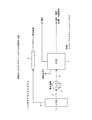
図1のとおり、従来のLNGサテライトシステムにおいては、LNGタンク1中のLNGは導管2を介して熱交換器3に供給される。LNGは熱交換器3で加熱されて気化し、コジェネレーションシステム(CGS)4に天然ガスとして供給される。コジェネレーションシステム(CGS)4には電力発生装置であるタービン発電機や燃料電池などが配置されており、天然ガスはタービン発電機あるいは燃料電池に供給されて電気と熱(排熱)を発生する。電気は需要者に供給され、排熱は給湯、冷暖房等の用途に供される。また、LNGタンク1からのボイルガスは排出導管5を介してパイプライン6によりサテライトステーション周辺の需要に供される。
As shown in FIG. 1, in the conventional LNG satellite system, the LNG in the
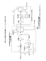
また、従来の水素分離型水蒸気改質器を用いた水素製造装置+二酸化炭素(CO2)回収装置については、燃料が都市ガスである場合を例にすると、以下のとおりである。図2のとおり、水素分離型改質器での水素製造用の燃料とする方の都市ガスは、導管11を介して脱硫器13に通して硫黄化合物を除去した後、水蒸気(スチーム)を添加、混合して水素分離型水蒸気改質器17に供給する。水素分離型水蒸気改質器において、脱硫済み都市ガスは水蒸気による改質により改質ガスとなり、改質ガス中の水素が水素分離膜つまり例えばPd系合金膜等の水素透過膜を選択的に透過して分離されて取り出される。
In addition, a hydrogen production apparatus + carbon dioxide (CO 2 ) recovery apparatus using a conventional hydrogen separation type steam reformer is as follows when the fuel is city gas. As shown in FIG. 2, the city gas used as the fuel for hydrogen production in the hydrogen separation reformer is passed through the
ボイラー15で燃焼して水蒸気発生用の燃料とする方の都市ガスは、導管11の分岐管12を介してボイラー15へ供給される。ボイラー15へ供給された都市ガスは、空気供給管14からボイラー15に供給される空気により燃焼し、水を加熱して水蒸気を発生させる。符号16はボイラー15への水供給管である。ボイラー15で発生した水蒸気は、脱硫器13で脱硫され圧縮機P1を経た都市ガスに混合され、水素分離型水蒸気改質器17に供給される。
The city gas burned in the
水素分離型水蒸気改質器17からのオフガスは圧縮機P2により圧縮した後、熱交換器19で冷却することによりオフガス中に含まれる二酸化炭素(CO2)を液化炭酸とする。液化炭酸は気液分離器21により分離し、導出管23により取り出され回収される。液化炭酸を分離したオフガス中にはCO、H2、CH4、CO2が含まれているので、水素分離型水蒸気改質器17の燃焼器18に供給してその可燃分を燃焼し、水蒸気改質器での水蒸気改質用の熱に利用される。
The off-gas from the hydrogen separation
〈本発明(1)の態様〉
図3は本発明(1)を説明する図である。
<Aspect of the present invention (1)>
FIG. 3 is a diagram for explaining the present invention (1).
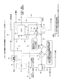
図3のとおり、本発明(1)の熱電気水素供給システムにおいては、LNGを気化して天然ガスとして燃料とするコジェネレーションシステム(CGS)38を備える。LNGタンク31中のLNGは導管32を介して熱交換器33に供給される。LNGは熱交換器33で加熱されて気化し、天然ガスとしてコジェネレーションシステム(CGS)38に供給される。その天然ガスの一部は、導管34を介してパイプライン35によりサテライトステーション周辺の需要に供される。
As shown in FIG. 3, the thermoelectric hydrogen supply system of the present invention (1) includes a cogeneration system (CGS) 38 that vaporizes LNG and uses it as natural gas as fuel. The LNG in the
コジェネレーションシステム(CGS)38には電力発生装置であるタービン発電機などが配置されている。天然ガスはガスタービン発電機に供給され、空気供給管39から供給され、酸素富化器40で酸素富化された空気で燃焼して電気と熱(排熱)を発生する。電気は需要者に供給され、排熱は給湯、冷暖房等の用途に供される。その排熱の一部は水素分離型水蒸気改質器45における天然ガスの水蒸気改質反応に供する水蒸気発生用に利用する。符号44は水素分離型水蒸気改質器45への水蒸気供給管である。
The cogeneration system (CGS) 38 is provided with a turbine generator that is a power generation device. Natural gas is supplied to a gas turbine generator, supplied from an
本発明(1)の熱電水素供給システムにおいては、コジェネレーションシステム(CGS)38及び、水素分離型水蒸気改質器45における水蒸気改質用の加熱源である燃焼器での燃焼用には酸素富化空気を使用する。供給管39を介して供給される空気は、酸素富化器40で酸素が富化される。供給管39中を流れる酸素富化空気は分岐管41を介してコジェネレーションシステム(CGS)38に供給され、電力発生装置であるガスタービン発電機に供給される天然ガスの燃焼用に使用される。
In the thermoelectric hydrogen supply system of the present invention (1), oxygen is enriched for combustion in the combustor which is a heating source for steam reforming in the cogeneration system (CGS) 38 and the hydrogen
酸素富化空気のうち分岐管41で分岐されない分は、供給管39を介して水素分離型水蒸気改質器45における天然ガスの水蒸気改質反応用加熱源である燃焼器46に供給される。コジェネレーションシステム(CGS)38で発生した排熱により水蒸気を生成し、水素分離型水蒸気改質器45での改質反応用に利用する。符号44は、水素分離型水蒸気改質器45への改質反応用水蒸気の供給管である。
A portion of the oxygen-enriched air that is not branched by the
水素分離型水蒸気改質器45からのオフガスは導出管48を介して導出され、圧縮機P1により圧縮した後、熱交換器33で冷却することによりオフガス中に含まれる二酸化炭素(CO2)を液化炭酸とする。液化炭酸は気液分離器49により分離し、導出管50により取り出され回収される。回収液化炭酸は溶接用、冷却用、食品用、製鋼用、化学用などの用途に利用される。
The off-gas from the hydrogen separation
コジェネレーションシステム(CGS)38で発生した燃焼排ガスと、水素分離型水蒸気改質器45における天然ガスの水蒸気改質反応用加熱源である燃焼器46からの燃焼排ガスと、水素分離型水蒸気改質器45からのオフガスの全部と、を一つに合流させた後、熱交換器33で冷却し、気液分離器49に導入する。
Combustion exhaust gas generated in the cogeneration system (CGS) 38, combustion exhaust gas from the
このように、熱交換器33において、その冷却源はLNGタンク31から導管32を介して供給されるLNGであり、LNGの冷熱を二酸化炭素の液化回収に利用するとともに、コジェネレーションシステム(CGS)38、水素分離型水蒸気改質器45からの排熱をLNGの気化に利用するものである。
Thus, in the
気液分離器49において、熱交換器33を経た合流ガス中の二酸化炭素は液化炭酸として分離する。液化炭酸は導出管50により取り出し回収され、溶接用、冷却用、食品用、製鋼用、化学用などの用途に利用される。また、気液分離槽49で分離されたガス(気相分)にはCO、H2、CH4、CO2などが含まれている。そのうちCO、H2、CH4は燃料となるので、気相分は導管51、52を介して導出され、燃焼器46での燃焼用燃料に利用する。また、気相分にはCO、H2が含まれているので、気相分の一部を導管53により導出し、浸炭などに利用する。
In the gas-
このように、本発明(1)においては、酸素富化空気を用い、LNGの冷熱を利用することにより、熱、電気を生成し、水素を製造するとともに、天然ガス由来の二酸化炭素の全量もしくは大部分を分離回収し、有効利用することができる。これにより、熱と電気だけでなく、水素や二酸化炭素を必要とする産業用施設、水素ステーションを併設する大型施設への適用が可能であり、エネルギーの効率的な利用と、二酸化炭素排出量の大幅削減が可能である。 Thus, in the present invention (1), by using oxygen-enriched air and utilizing the cold heat of LNG, heat and electricity are generated to produce hydrogen, and the total amount of carbon dioxide derived from natural gas or The majority can be separated and recovered for effective use. As a result, it can be applied not only to heat and electricity, but also to industrial facilities that require hydrogen and carbon dioxide, and large facilities with hydrogen stations. Significant reduction is possible.
また、従来技術においては、図2のとおり、ボイラーが必須であるが、本発明(1)においては、コジェネレーションシステム(CGS)38において発生する余剰熱を利用して水蒸気を生成するのでボイラーは不要である。 In the prior art, as shown in FIG. 2, a boiler is indispensable. However, in the present invention (1), steam is generated using surplus heat generated in the cogeneration system (CGS) 38. It is unnecessary.
〈本発明(2)の態様〉
図4は本発明(2)を説明する図である。
<Aspect of the present invention (2)>
FIG. 4 is a diagram for explaining the present invention (2).
図4のとおり、本発明(2)の熱電気水素供給システムにおいては、LNGを気化して天然ガスとして燃料とするコジェネレーションシステム(CGS)67を備える。LNGタンク61中のLNGは導管62を介して熱交換器63に供給される。LNGは熱交換器63で加熱されて気化し、天然ガスとしてコジェネレーションシステム(CGS)67に供給される。その天然ガスの一部は、導管64を介してパイプライン65によりサテライトステーション周辺の需要に供される。
As shown in FIG. 4, the thermoelectric hydrogen supply system of the present invention (2) includes a cogeneration system (CGS) 67 that vaporizes LNG and uses it as fuel as natural gas. The LNG in the
コジェネレーションシステム(CGS)67には電力発生装置であるガスタービン発電機などが配置されている。コジェネレーションシステム(CGS)67において、天然ガスはガスタービン発電機に供給され、空気供給管68から供給され、酸素富化器69で酸素富化された空気で燃焼して電気と熱(排熱)を発生する。電気は需要者に供給され、排熱は給湯、冷暖房等の用途に供される。その排熱の一部は水素分離型水蒸気改質器72における天然ガスの水蒸気改質反応に供する水蒸気発生用に利用する。
The cogeneration system (CGS) 67 is provided with a gas turbine generator that is a power generation device. In a cogeneration system (CGS) 67, natural gas is supplied to a gas turbine generator, supplied from an
符号71は、水素分離型水蒸気改質器72への水蒸気供給管である。水素分離型水蒸気改質器72では原燃料である天然ガスを水蒸気改質反応により改質する。天然ガスは、熱交換器63で気化し、導管62を流れる天然ガスを分岐管66で分岐し、水蒸気供給管71を流れる水蒸気と合流して水素分離型水蒸気改質器72へ供給される。
本発明(2)の熱電水素供給システムにおいては、コジェネレーションシステム(CGS)67での排熱を水素分離型水蒸気改質器72における水蒸気改質用の加熱に利用する。符号69は、そのためのコジェネレーションシステム(CGS)67から水素分離型水蒸気改質器72への排ガス供給管である。
In the thermoelectric hydrogen supply system of the present invention (2), the exhaust heat from the cogeneration system (CGS) 67 is used for heating for steam reforming in the hydrogen
供給管68を介して供給される空気は、酸素富化器69で酸素が富化される。供給管68中を流れる酸素富化空気はコジェネレーションシステム(CGS)67に供給され、電力発生装置であるガスタービン発電機に供給される天然ガスの燃焼用に使用される。
The air supplied through the
コジェネレーションシステム(CGS)67からの燃焼排ガスは、導管69を介して水素分離型水蒸気改質器72の加熱部73に供給され、水素分離型水蒸気改質器72における天然ガスの水蒸気改質反応用加熱源として利用される。コジェネレーションシステム(CGS)67で発生した排熱により水蒸気を生成し、水素分離型水蒸気改質器72での改質反応用に利用する。符号71は、水素分離型水蒸気改質器72への改質反応用の水蒸気供給管である。
The combustion exhaust gas from the cogeneration system (CGS) 67 is supplied to the
導管69を介して供給され、加熱部73を経たコジェネレーションシステム(CGS)67からの排ガスは、水素分離型水蒸気改質器72における天然ガスの水蒸気改質反応用加熱源として利用することから、その排ガス自体は冷却されているが、導出管75を流れる水素分離型水蒸気改質器72からのオフガス導出管75を流れるオフガスに合流させる。合流ガスは、導管76中を流れ、圧縮機P1により圧縮した後、熱交換器63で冷却する。
The exhaust gas supplied from the cogeneration system (CGS) 67 supplied through the
熱交換器63において、その冷却源はLNGタンク61から導管62を介して供給されるLNGであり、LNGの冷熱を二酸化炭素の液化回収に利用する。また逆に、コジェネレーションシステム(CGS)67、水素分離型水蒸気改質器72からの排熱をLNGの気化に利用するものである。
In the
二酸化炭素は、(a)加熱部73を経たコジェネレーションシステム(CGS)67からの排ガスと、(b)水素分離型水蒸気改質器72からのオフガスの合流ガスであるので、合流ガス中に含まれる二酸化炭素(CO2)をすべて液化炭酸にする。
Since carbon dioxide is a combined gas of (a) the exhaust gas from the cogeneration system (CGS) 67 that has passed through the
液化炭酸は気液分離器77により分離し、導出管78により取り出し、回収され、その用途に利用される。気液分離器77において、熱交換器63を経た合流ガス中の二酸化炭素は実質上、すべて液化炭酸として分離する。気液分離槽77で分離されたガス(気相分)にはCO、H2、CH4、CO2などが含まれている。そのうちCO、H2、CH4は燃料になるので、気相分は導出管79を介して導出し、コジェネレーションシステム(CGS)67での燃焼用燃料に利用する。また、気相分にはCO、H2が含まれているので、気相分の一部を導出管80により導出し、浸炭などの用途に利用する。
The liquefied carbon dioxide is separated by a gas-
このように、本発明(2)においては、酸素富化空気とLNGの冷熱を用いることにより、熱、電気を発生し、水素を製造するとともに、天然ガス由来の二酸化炭素の全量または大部分を分離回収し、有効利用することができる。これにより、熱と電気だけでなく、水素や二酸化炭素を必要とする産業用施設、水素ステーションを併設する大型施設への適用が可能であり、エネルギーの効率的な利用と、二酸化炭素排出量の大幅削減が可能である。 As described above, in the present invention (2), by using oxygen-enriched air and the cold heat of LNG, heat and electricity are generated, hydrogen is produced, and all or most of carbon dioxide derived from natural gas is produced. It can be separated and recovered for effective use. As a result, it can be applied not only to heat and electricity, but also to industrial facilities that require hydrogen and carbon dioxide, and large facilities with hydrogen stations. Significant reduction is possible.
また、従来技術においては、図2のとおり、ボイラーが必須であるが、本発明(2)においては、図4のとおり、CGS(コジェネレーションシステム)67において発生する余剰熱を利用して水蒸気を生成するのでボイラーは不要である。 In the prior art, a boiler is indispensable as shown in FIG. 2, but in the present invention (2), as shown in FIG. 4, steam is generated using surplus heat generated in a CGS (cogeneration system) 67 as shown in FIG. A boiler is not necessary because it generates.
1 LNGタンク
2 導管
3 熱交換器
4 コジェネレーションシステム(CGS)
5 LNGタンク1からのボイルオフガス排出導管
6 パイプライン
11 都市ガス導管
12 都市ガス導管11からの分岐管
13 脱硫器
14 空気供給管
15 ボイラー
16 ボイラー15への水供給管
17 水素分離型水蒸気改質器
P1、P2 圧縮機
18 燃焼器
21 気液分離器
23 液化炭酸の導出管
31 LNGタンク
33 熱交換器
38 天然ガスを燃料とするコジェネレーションシステム(CGS)
39 空気供給管
40 酸素富化器
41 酸素富化空気の分岐管
44 水素分離型水蒸気改質器45への水蒸気供給管
45 水素分離型水蒸気改質器
46 燃焼器
49 気液分離器
52、53 気相分導出管
61 LNGタンク
62 LNG導管
63 熱交換器
64 天然ガス導管
65 パイプライン
67 天然ガスを燃料とするコジェネレーションシステム(CGS)
68 空気供給管
69 酸素富化器
70 温水、水蒸気等の導出管
71 水素分離型水蒸気改質器72への水蒸気供給管
72 水素分離型水蒸気改質器
73 水素分離型水蒸気改質器72の加熱部
75 オフガス導出管
76 合流ガス導管
77 気液分離器
78 液化炭酸の導出管
79、80 気相分導出管
1
5 Boil-off gas discharge pipe from
DESCRIPTION OF
68
Claims (5)
(a)前記コジェネレーションシステムからの排ガスと前記水素分離型水蒸気改質器からのオフガスを合流させ、
(b)前記排ガス及びオフガスをその流れ方向でみて、順次、圧縮機、冷却熱交換器及び気液分離槽を含む二酸化炭素回収装置を備えてなり、
(c)前記冷却熱交換器の冷熱として前記LNGを使用し、
(d)前記コジェネレーションシステム及び前記水蒸気改質用加熱源である燃焼器には酸素富化空気を使用するようにしてなる、
ことを特徴とする熱電気水素供給システム。 Cogeneration system using natural gas vaporized LNG as fuel, hydrogen separation type steam reformer by steam reforming of the natural gas, and combustor which is the steam reforming heating source, electricity, and A system for supplying hydrogen,
(A) combining the exhaust gas from the cogeneration system and the off-gas from the hydrogen separation steam reformer,
(B) Looking at the exhaust gas and off-gas in the flow direction, and sequentially comprising a carbon dioxide recovery device including a compressor, a cooling heat exchanger and a gas-liquid separation tank,
(C) using the LNG as the cooling heat of the cooling heat exchanger;
(D) Oxygen-enriched air is used for the cogeneration system and the combustor that is the heating source for steam reforming.
A thermoelectric hydrogen supply system characterized by that.
(a)前記コジェネレーションシステムからの排ガスを前記ヒーターの熱源として使用した後、
(b)前記排ガスと前記水素分離型水蒸気改質器からのオフガスを合流させ、
(c)前記排ガス及びオフガスをその流れ方向でみて、順次、圧縮機、冷却熱交換器及び気液分離槽を含む二酸化炭素回収装置を備えてなり、
(d)前記冷却熱交換器の冷熱として前記LNGを使用し、
(e)前記コジェネレーションシステムには酸素富化空気を使用するようにしてなる、
ことを特徴とする熱電気水素供給システム。 Heat, electricity and hydrogen comprising a cogeneration system using natural gas vaporized LNG as a fuel, a hydrogen separation type steam reformer by steam reforming of the natural gas, and a heater which is the heating source for steam reforming A system for supplying
(A) After using the exhaust gas from the cogeneration system as a heat source for the heater,
(B) combining the off-gas from the exhaust gas and the hydrogen separation steam reformer,
(C) Looking at the exhaust gas and off-gas in the flow direction, and sequentially comprising a carbon dioxide recovery device including a compressor, a cooling heat exchanger and a gas-liquid separation tank,
(D) using the LNG as the cooling heat of the cooling heat exchanger;
(E) The cogeneration system uses oxygen-enriched air.
A thermoelectric hydrogen supply system characterized by that.
The thermoelectric hydrogen supply system according to any one of claims 1 to 4, wherein the thermoelectric hydrogen supply system is a thermoelectric hydrogen supply system installed at an on-site type hydrogen station.
Priority Applications (1)
| Application Number | Priority Date | Filing Date | Title |
|---|---|---|---|
| JP2009259349A JP5143812B2 (en) | 2009-11-12 | 2009-11-12 | Thermoelectric hydrogen supply system |
Applications Claiming Priority (1)
| Application Number | Priority Date | Filing Date | Title |
|---|---|---|---|
| JP2009259349A JP5143812B2 (en) | 2009-11-12 | 2009-11-12 | Thermoelectric hydrogen supply system |
Publications (2)
| Publication Number | Publication Date |
|---|---|
| JP2011106295A true JP2011106295A (en) | 2011-06-02 |
| JP5143812B2 JP5143812B2 (en) | 2013-02-13 |
Family
ID=44230050
Family Applications (1)
| Application Number | Title | Priority Date | Filing Date |
|---|---|---|---|
| JP2009259349A Expired - Fee Related JP5143812B2 (en) | 2009-11-12 | 2009-11-12 | Thermoelectric hydrogen supply system |
Country Status (1)
| Country | Link |
|---|---|
| JP (1) | JP5143812B2 (en) |
Cited By (3)
| Publication number | Priority date | Publication date | Assignee | Title |
|---|---|---|---|---|
| CN113897229A (en) * | 2021-11-05 | 2022-01-07 | 星恩杰气体(上海)有限公司 | Marine LNG gas supply system with carbon capture function |
| CN116767476A (en) * | 2023-05-24 | 2023-09-19 | 武汉理工大学 | Ship composite power system and control method and device thereof |
| JP7557759B1 (en) * | 2023-10-23 | 2024-09-30 | 株式会社 ユーリカ エンジニアリング | Combined heat and power supply integrated synthesis gas production system and combined heat and power supply integrated synthesis gas production method |
Citations (6)
| Publication number | Priority date | Publication date | Assignee | Title |
|---|---|---|---|---|
| US4602477A (en) * | 1985-06-05 | 1986-07-29 | Air Products And Chemicals, Inc. | Membrane-aided distillation for carbon dioxide and hydrocarbon separation |
| JPH04334729A (en) * | 1991-05-08 | 1992-11-20 | Toyo Eng Corp | Power generating method |
| JP2000247604A (en) * | 1999-02-25 | 2000-09-12 | Toshiba Corp | Hydrogen production apparatus and method |
| JP2002122030A (en) * | 2000-10-16 | 2002-04-26 | Kobe Steel Ltd | Facility for co-producing power and hydrogen |
| JP2005226596A (en) * | 2004-02-16 | 2005-08-25 | Jfe Engineering Kk | Power generation function combined hydrogen production method and apparatus |
| JP2009143744A (en) * | 2007-12-12 | 2009-07-02 | Petroleum Energy Center | Energy station |
-
2009
- 2009-11-12 JP JP2009259349A patent/JP5143812B2/en not_active Expired - Fee Related
Patent Citations (6)
| Publication number | Priority date | Publication date | Assignee | Title |
|---|---|---|---|---|
| US4602477A (en) * | 1985-06-05 | 1986-07-29 | Air Products And Chemicals, Inc. | Membrane-aided distillation for carbon dioxide and hydrocarbon separation |
| JPH04334729A (en) * | 1991-05-08 | 1992-11-20 | Toyo Eng Corp | Power generating method |
| JP2000247604A (en) * | 1999-02-25 | 2000-09-12 | Toshiba Corp | Hydrogen production apparatus and method |
| JP2002122030A (en) * | 2000-10-16 | 2002-04-26 | Kobe Steel Ltd | Facility for co-producing power and hydrogen |
| JP2005226596A (en) * | 2004-02-16 | 2005-08-25 | Jfe Engineering Kk | Power generation function combined hydrogen production method and apparatus |
| JP2009143744A (en) * | 2007-12-12 | 2009-07-02 | Petroleum Energy Center | Energy station |
Cited By (3)
| Publication number | Priority date | Publication date | Assignee | Title |
|---|---|---|---|---|
| CN113897229A (en) * | 2021-11-05 | 2022-01-07 | 星恩杰气体(上海)有限公司 | Marine LNG gas supply system with carbon capture function |
| CN116767476A (en) * | 2023-05-24 | 2023-09-19 | 武汉理工大学 | Ship composite power system and control method and device thereof |
| JP7557759B1 (en) * | 2023-10-23 | 2024-09-30 | 株式会社 ユーリカ エンジニアリング | Combined heat and power supply integrated synthesis gas production system and combined heat and power supply integrated synthesis gas production method |
Also Published As
| Publication number | Publication date |
|---|---|
| JP5143812B2 (en) | 2013-02-13 |
Similar Documents
| Publication | Publication Date | Title |
|---|---|---|
| US7634915B2 (en) | Systems and methods for power generation and hydrogen production with carbon dioxide isolation | |
| ES2963067T3 (en) | Ammonia cracking | |
| ES3018207T3 (en) | System and method for power production with integrated production of hydrogen | |
| JP6951613B1 (en) | Carbon dioxide recovery hydrogen production system utilizing LNG | |
| JP5280343B2 (en) | Hydrogen separation type hydrogen production system with carbon dioxide separation and recovery equipment | |
| CN1116501C (en) | Processes for the production of electricity, steam and carbon dioxide from hydrocarbon feedstocks | |
| US20030008183A1 (en) | Zero/low emission and co-production energy supply station | |
| Verda et al. | Thermodynamic and economic optimization of a MCFC-based hybrid system for the combined production of electricity and hydrogen | |
| US20090117024A1 (en) | Process for the Production of Hydrogen with Co-Production and Capture of Carbon Dioxide | |
| JP2008163944A (en) | Reforming system for a partial CO2 recovery cycle plant | |
| WO2007021909A2 (en) | Hydrogen production from an oxyfuel combustor | |
| Ortiz et al. | Optimization of power and hydrogen production from glycerol by supercritical water reforming | |
| JP5412232B2 (en) | Hydrogen separation type hydrogen production system with carbon dioxide separation and recovery equipment | |
| CA2446333A1 (en) | Hydrogen generation | |
| JP5280348B2 (en) | Hybrid hydrogen production system | |
| JP5143812B2 (en) | Thermoelectric hydrogen supply system | |
| JP4632532B2 (en) | Hydrogen production method and system | |
| RU2471080C2 (en) | Method to operate power plant with integrated gasification, and also power plant | |
| Cioli et al. | Decarbonisation options for the Dutch industrial gases production | |
| JP2004018343A (en) | Method for co-producing electric power and hydrogen from hydrocarbon fuel, its plant and its waste heat recovery type reformer | |
| JP4744971B2 (en) | Low quality waste heat recovery system | |
| JP5148541B2 (en) | Hydrogen separation type hydrogen production system using oxygen combustion technology | |
| JP7025310B2 (en) | Gas turbine combined cycle power generation system, gas turbine combined cycle power generation method | |
| CN120265571A (en) | Methods and systems for carbon neutral power generation | |
| JP2002161815A (en) | Multi fuel supply system |
Legal Events
| Date | Code | Title | Description |
|---|---|---|---|
| A621 | Written request for application examination |
Free format text: JAPANESE INTERMEDIATE CODE: A621 Effective date: 20120131 |
|
| A977 | Report on retrieval |
Free format text: JAPANESE INTERMEDIATE CODE: A971007 Effective date: 20121026 |
|
| TRDD | Decision of grant or rejection written | ||
| A01 | Written decision to grant a patent or to grant a registration (utility model) |
Free format text: JAPANESE INTERMEDIATE CODE: A01 Effective date: 20121120 |
|
| A01 | Written decision to grant a patent or to grant a registration (utility model) |
Free format text: JAPANESE INTERMEDIATE CODE: A01 |
|
| A61 | First payment of annual fees (during grant procedure) |
Free format text: JAPANESE INTERMEDIATE CODE: A61 Effective date: 20121121 |
|
| FPAY | Renewal fee payment (event date is renewal date of database) |
Free format text: PAYMENT UNTIL: 20151130 Year of fee payment: 3 |
|
| R150 | Certificate of patent or registration of utility model |
Free format text: JAPANESE INTERMEDIATE CODE: R150 |
|
| LAPS | Cancellation because of no payment of annual fees |