JP2011106263A - Tamper of screed for road finisher - Google Patents
Tamper of screed for road finisher Download PDFInfo
- Publication number
- JP2011106263A JP2011106263A JP2010255632A JP2010255632A JP2011106263A JP 2011106263 A JP2011106263 A JP 2011106263A JP 2010255632 A JP2010255632 A JP 2010255632A JP 2010255632 A JP2010255632 A JP 2010255632A JP 2011106263 A JP2011106263 A JP 2011106263A
- Authority
- JP
- Japan
- Prior art keywords
- eccentric
- tappet
- tamper
- eccentric shaft
- circumferential
- Prior art date
- Legal status (The legal status is an assumption and is not a legal conclusion. Google has not performed a legal analysis and makes no representation as to the accuracy of the status listed.)
- Granted
Links
Images


Classifications
-
- E—FIXED CONSTRUCTIONS
- E01—CONSTRUCTION OF ROADS, RAILWAYS, OR BRIDGES
- E01C—CONSTRUCTION OF, OR SURFACES FOR, ROADS, SPORTS GROUNDS, OR THE LIKE; MACHINES OR AUXILIARY TOOLS FOR CONSTRUCTION OR REPAIR
- E01C19/00—Machines, tools or auxiliary devices for preparing or distributing paving materials, for working the placed materials, or for forming, consolidating, or finishing the paving
- E01C19/22—Machines, tools or auxiliary devices for preparing or distributing paving materials, for working the placed materials, or for forming, consolidating, or finishing the paving for consolidating or finishing laid-down unset materials
- E01C19/30—Tamping or vibrating apparatus other than rollers ; Devices for ramming individual paving elements
- E01C19/34—Power-driven rammers or tampers, e.g. air-hammer impacted shoes for ramming stone-sett paving; Hand-actuated ramming or tamping machines, e.g. tampers with manually hoisted dropping weight
- E01C19/40—Power-driven rammers or tampers, e.g. air-hammer impacted shoes for ramming stone-sett paving; Hand-actuated ramming or tamping machines, e.g. tampers with manually hoisted dropping weight adapted to impart a smooth finish to the paving, e.g. tamping or vibrating finishers
- E01C19/407—Power-driven rammers or tampers, e.g. air-hammer impacted shoes for ramming stone-sett paving; Hand-actuated ramming or tamping machines, e.g. tampers with manually hoisted dropping weight adapted to impart a smooth finish to the paving, e.g. tamping or vibrating finishers with elements or parts partly or fully immersed in or penetrating into the material to act thereon, e.g. immersed vibrators or vibrating parts, kneading tampers, spaders
-
- E—FIXED CONSTRUCTIONS
- E01—CONSTRUCTION OF ROADS, RAILWAYS, OR BRIDGES
- E01C—CONSTRUCTION OF, OR SURFACES FOR, ROADS, SPORTS GROUNDS, OR THE LIKE; MACHINES OR AUXILIARY TOOLS FOR CONSTRUCTION OR REPAIR
- E01C19/00—Machines, tools or auxiliary devices for preparing or distributing paving materials, for working the placed materials, or for forming, consolidating, or finishing the paving
- E01C19/48—Machines, tools or auxiliary devices for preparing or distributing paving materials, for working the placed materials, or for forming, consolidating, or finishing the paving for laying-down the materials and consolidating them, or finishing the surface, e.g. slip forms therefor, forming kerbs or gutters in a continuous operation in situ
- E01C19/4833—Machines, tools or auxiliary devices for preparing or distributing paving materials, for working the placed materials, or for forming, consolidating, or finishing the paving for laying-down the materials and consolidating them, or finishing the surface, e.g. slip forms therefor, forming kerbs or gutters in a continuous operation in situ with tamping or vibrating means for consolidating or finishing, e.g. immersed vibrators, with or without non-vibratory or non-percussive pressing or smoothing means
-
- F—MECHANICAL ENGINEERING; LIGHTING; HEATING; WEAPONS; BLASTING
- F16—ENGINEERING ELEMENTS AND UNITS; GENERAL MEASURES FOR PRODUCING AND MAINTAINING EFFECTIVE FUNCTIONING OF MACHINES OR INSTALLATIONS; THERMAL INSULATION IN GENERAL
- F16C—SHAFTS; FLEXIBLE SHAFTS; ELEMENTS OR CRANKSHAFT MECHANISMS; ROTARY BODIES OTHER THAN GEARING ELEMENTS; BEARINGS
- F16C3/00—Shafts; Axles; Cranks; Eccentrics
- F16C3/04—Crankshafts, eccentric-shafts; Cranks, eccentrics
- F16C3/22—Cranks; Eccentrics
- F16C3/28—Adjustable cranks or eccentrics
Abstract
Description
本発明は、特許請求項1の前文部分に記載のタンパに関する。
The present invention relates to a tamper according to the preamble of
タンパは、敷設材を予め締め固めるタンピング装置の一般的な用語であり、道路仕上げ機のスクリードの標準装備の一部である。スクリードは、基本スクリードと、任意に有効幅を変更するために基本スクリードで伸縮できる伸縮可能なスクリードと、必要に応じて任意に取付けるスクリードの拡張部品を含む。これらのスクリードの構成要素は夫々、個別の駆動モータ、典型的には速度で制御される油圧モータを有する少なくとも1つのタンパを備えている。タンパは、スクリード内で単独で事前締め固めの作用をするか、スクリードプレートで不平衡脈動を発生し、事前締め固めに貢献する不平衡質量振動発生器との組合せで作用する。 Tamper is a general term for a tamping device that pre-compacts the laying material and is part of the standard equipment of screeds for road finishing machines. The screed includes a basic screed, a telescoping screed that can be expanded and contracted with the basic screed to change the effective width, and a screed expansion part that is optionally attached as required. Each of these screed components comprises at least one tamper having a separate drive motor, typically a hydraulic motor controlled at speed. The tamper acts alone in the screed alone or in combination with an unbalanced mass vibration generator that generates unbalanced pulsations in the screed plate and contributes to pre-compaction.
不平衡質量振動発生器と組合せた、又は組合せないタンパが、例えば、ヨゼフ フェゲーレ アーゲー社(独国マンハイム(Mannheim)68146)の1997年の技術文献“Fur jede Aufgabe die richtige Einbaubohle”No.2400/10/2の4、8、9、11〜15頁で知られている。 A tamper combined with or without an unbalanced mass vibration generator is described, for example, in the technical document “Fur Jade Aufbeige dierichubehule” No. 1997 of Joseph Fegele AG (Mannheim 68146). 2400/10/2, pages 4, 8, 9, 11-15.
舗装厚さが変更されるとき、一定の事前締め固めを行なうために、例えば、道路仕上げ機の牽引棒の関節点の垂直位置を調整して、スクリードが外部コントロールスタンドで調整される際でも、タンパバーのストロークを変更して舗装厚さに適応させることが知られている。この既知のタンパ(文献“Fur jede Aufgabe die richtige Einbaubohle”2頁の左下)では、これを、敷設の中断中に、コネクティングロッドの偏心ブッシュを、偏心軸の偏心部分に対して回転させ、再び別の相対的な回転位置で、トルクに耐えるよう偏心軸に固定して、達成している。そのために、複数設けたコネクティングロッドの各々で緊張リングの少なくとも1個の緊張ネジを緩めて、例えば偏心ブッシュに対して偏心軸を回転させて、再び緊張リングを固定する必要がある。偏心軸の偏心部分と偏心ブッシュの2偏心間の相対的な回転位置に応じた全体の偏心度が、結果的に有効なタンパバーストロークの半分に相当する。タンパの動作中、緊張リングは完全にではなく固定されている。
When the pavement thickness is changed, even when the screed is adjusted with an external control stand, for example, by adjusting the vertical position of the joint point of the towing bar of the road finishing machine to perform a certain pre-consolidation, It is known to change the tamper bar stroke to adapt to the pavement thickness. In this known tamper (lower left of
例えば、8本のコネクティングロッドを基本スクリードに設けると、8つの調整操作が必要となる。また、スクリードが、伸縮スクリード及び/又はスクリード拡張部品を含む場合には、更に多くの調整操作がそこに配設したタンパに必要となる。これには、時間がかかり、有効幅全体を一定に事前締め固めするのに細心の注意が必要となる。 For example, if eight connecting rods are provided on the basic screed, eight adjustment operations are required. Further, when the screed includes a telescoping screed and / or a screed extension component, more adjustment operations are required for the tamper disposed there. This takes time and requires careful attention to pre-compact the entire effective width.
大抵は、舗装厚さが薄い場合、タンパバーのストロークを小さくするのが適切であり、一方舗装厚さが厚い場合、ストロークを大きくするのが適切である。調整する舗装厚さは夫々で必然的に異なる、或いは意図的に変えねばならないので、調整する舗装厚さに対して選択したタンパバーのストロークを、少なくとも制限された範囲内で迅速、精確に、且つ時間がかかる手動の調整操作なしに変更可能にするのが適切である。 In most cases, when the pavement thickness is thin, it is appropriate to reduce the stroke of the tamper bar, while when the pavement thickness is thick, it is appropriate to increase the stroke. Since the pavement thickness to be adjusted is inevitably different or deliberately changed, the tamper bar stroke selected for the pavement thickness to be adjusted can be quickly, accurately and at least within a limited range. It is appropriate to be able to change without time-consuming manual adjustment operations.
欧州特許出願公開第0374428号明細書には、緊張リングによって偏心部分の各停止位置に偏心ブッシュを固定する道路仕上げ機のスクリードのタンパが記載されている。緊張リングを工具で緩めた後に、偏心ブッシュを偏心部分に対し新たな回転位置まで回転させ、緊張リングが再び偏心部分に固定される前に、タンパストロークを変更する。緊張リングは制限なく回転できるので、新たなタンパストロークが所望通りかどうかを確認するために、新たな調整についてまずチェックしなければならない。タンパストロークを変更するには、スクリードの操作を長く中断したり、少なくとも1つの工具で緊張リングに手動操作したりする必要がある。そうした操作は、スクリード内部で複数回、つまり偏心ブッシュ毎に行うため、厄介で時間がかかる。 EP 0 374 428 describes a screed tamper of a road finishing machine in which an eccentric bush is fixed to each stop position of the eccentric part by means of a tension ring. After loosening the tension ring with a tool, the eccentric bushing is rotated relative to the eccentric part to a new rotational position, and the tamper stroke is changed before the tension ring is again secured to the eccentric part. Since the tension ring can rotate without restriction, a new adjustment must first be checked to see if the new tamper stroke is as desired. To change the tamper stroke, it is necessary to interrupt the screed operation for a long time or to manually operate the tension ring with at least one tool. Such an operation is performed several times inside the screed, that is, for each eccentric bush, which is cumbersome and time consuming.
独国特許出願公開第3127377号明細書に記載されたタンパでは、偏心ブッシュの偏心度が、緊張リングのネジを緩めた後に、調整ネジを変えることで変更できる。タンパストロークを変更するのに、スクリードの動作を長く中断し、工具を用いた手動操作が必要である。 In the tamper described in German Patent Application Publication No. 3127377, the eccentricity of the eccentric bush can be changed by changing the adjusting screw after loosening the screw of the tension ring. In order to change the tamper stroke, it is necessary to interrupt the operation of the screed for a long time and perform manual operation using a tool.
英国特許出願公開第742141号明細書及び英国特許出願公開第760725号明細書には夫々、クランクプレスの偏心クランク駆動部について開示している。偏心ブッシュは緊張リングによって偏心軸に固定される。工具で操作した後でも、偏心ブッシュは少なくとも1箇所の他の所定回転位置に調整することができる。 GB-A-742141 and UK-A-760725 disclose an eccentric crank drive of a crank press, respectively. The eccentric bush is fixed to the eccentric shaft by a tension ring. Even after operating with a tool, the eccentric bush can be adjusted to at least one other predetermined rotational position.
独国実用新案出願公開第202005006059号明細書は、油圧モータで回転駆動される不平衡要素を有するアドオン型コンパクタに関し、その回転方向が反転できる。不平衡要素は、選択した回転方向に応じて異なる相対位置をとり、地面に面しているコンパクタプレートに対する励振力を変更することができる。 German Utility Model Application Publication No. 20200506059 relates to an add-on compactor having an unbalanced element that is rotationally driven by a hydraulic motor, and the direction of rotation can be reversed. The unbalanced element can take different relative positions depending on the selected direction of rotation and change the excitation force on the compactor plate facing the ground.
国際出願公開第00/55430号明細書は、地盤処理のため変調した多周波振動で駆動される複数の不平衡質量振動発生器に関する。このコンパクタ集合体では、複数の偏心質量の回転による遠心力を用いて揺動自在に作業を行なう。複数の動力セルが、地盤に作用する1つの伝達質量に接続されている。各セルは、それ自体が駆動モータを有する。伝達質量で生成される動力ベクトル図は、個々の動力セルごとに偏心質量の回転数、回転方向、位相位置について個別に制御して変更できる。 WO 00/55430 relates to a plurality of unbalanced mass vibration generators driven by modulated multi-frequency vibrations for ground treatment. In this compactor assembly, the work is performed in a swingable manner by using a centrifugal force generated by the rotation of a plurality of eccentric masses. A plurality of power cells are connected to one transmission mass acting on the ground. Each cell has its own drive motor. The power vector diagram generated by the transmission mass can be changed by individually controlling the rotational speed, rotation direction, and phase position of the eccentric mass for each power cell.
本発明の基本的な目的は、迅速、精確に、且つ手動による調整作業無しにストロークの少なくとも1つの変化を可能にする、冒頭に記載した種類のタンパを提供することである。 The basic object of the present invention is to provide a tamper of the kind described at the outset which allows at least one change of stroke, quickly, accurately and without manual adjustment.
この目的は、特許請求項1の特徴部分によって達成される。
This object is achieved by the characterizing part of
回転方向を反転できる油圧又は電気モータ、又は固定回転方向での回転方向を反転させる変換ギアを有する油圧又は電気モータを、偏心軸の駆動部として使用する。駆動モータ又は反転ギアによって偏心軸の回転方向を反転させるだけで、タンパバーの調整ストロークを、事前に定められた選定範囲内で手動調整作業無しに変更して、例えば、舗装厚さの変化に迅速に精確に適応させることができる。回転方向を反転させることで、質量又は締め固め抵抗の力によって偏心軸の偏心部分に対する偏心ブッシュの回転抵抗が生じるために、タペットと事前選定領域との間の相対的な回転運動が起き、この運動によりタペットを、事前選定領域の片方の停止位置から他方の各停止位置に移動させる。その結果、偏心ブッシュと偏心軸の偏心部分との相対的な回転位置が変化し、偏心軸の偏心部分と偏心ブッシュの2つの個々の偏心度から新たな合計偏心度が調整されるが、新たな合計偏心度は新たなタンパバーストロークの半分に相当する。夫々の調整されたタペット停止位置で、そのときに有効な回転方向でトルクに耐えるように、偏心ブッシュは偏心軸に結合される。所定のストローク差は、例えば事前選定領域及び/又はタペットの周方向延伸部に関する弧度法で敷設条件に応じて選択でき、タンパバーの2つ異なるストロークの間で、ストロークを大きくする又は小さくする変化は、回転方向を変化させるだけで行なえる。各タペットが偏心ブッシュに設けられた場合、機能に関連する事前選定領域は偏心軸に配置される。逆の配列も、同様に可能であり、機能する。回転方向の反転を、オペレータが、例えば道路仕上げ機の運転台から及び/又はスクリードの外部コントロールスタンドから、制御可能にする、或いは、舗装厚さ及び/又は敷設速度等の少なくとも1つの敷設パラメタの変化に応じて、例えば道路仕上げ機の制御装置によって、調整する敷設速度及び/舗装厚さを考慮して、自動制御しておいてもよい。これにより、運転者や人員が、事前締め固めの達成度を常に目視により点検することから、及び/又は回転方向の反転を敷設速度及び/又は舗装厚さを変更後に適切か否かを検査する必要から解放される。また、回転方向の反転は、駆動モータの回転方向が変わらないようにして可逆転ギアにより実行できる。全ての偏心軸に設けたギアボックス又は駆動モータが、適切に並列に接続され、それによって回転方向の反転が、全タンパに対して単一の変更操作で実行することができる。 A hydraulic or electric motor that can reverse the rotation direction, or a hydraulic or electric motor that has a conversion gear that reverses the rotation direction in the fixed rotation direction is used as the drive unit for the eccentric shaft. By simply reversing the rotation direction of the eccentric shaft with a drive motor or reversing gear, the tamper bar adjustment stroke can be changed within a predetermined selection range without manual adjustment work, for example, to quickly change the pavement thickness. Can be adapted precisely. Reversing the direction of rotation causes the rotational resistance of the eccentric bushing against the eccentric part of the eccentric shaft due to the mass or the force of the compaction resistance, causing a relative rotational movement between the tappet and the preselected area. The tappet is moved from one stop position in the pre-selected region to the other stop position by the movement. As a result, the relative rotational position of the eccentric bush and the eccentric portion of the eccentric shaft changes, and a new total eccentricity is adjusted from the two individual eccentricities of the eccentric portion of the eccentric shaft and the eccentric bush. A total eccentricity is equivalent to half of the new tamper bar stroke. In each adjusted tappet stop position, the eccentric bushing is coupled to the eccentric shaft so as to withstand torque in the effective rotational direction at that time. The predetermined stroke difference can be selected according to the laying conditions, for example, in the arc selection method for the preselected region and / or the circumferential extension of the tappet, and the change that increases or decreases the stroke between the two different strokes of the tamper bar. This can be done simply by changing the direction of rotation. When each tappet is provided on an eccentric bush, a preselected area related to the function is arranged on the eccentric shaft. The reverse arrangement is possible and works as well. The reversal of the direction of rotation can be controlled by the operator, for example from the cab of the road finishing machine and / or from an external control stand of the screed, or at least one laying parameter such as pavement thickness and / or laying speed Depending on the change, automatic control may be performed in consideration of the laying speed and / or pavement thickness to be adjusted, for example, by a control device of a road finishing machine. This ensures that drivers and personnel always check the degree of advance compaction by visual inspection and / or whether the reversal of rotation direction is appropriate after changing the laying speed and / or pavement thickness. Freed from need. Further, the reversal of the rotation direction can be executed by the reversible gear so that the rotation direction of the drive motor does not change. Gearboxes or drive motors provided on all eccentric shafts are suitably connected in parallel, so that reversal of the rotational direction can be carried out with a single change operation for all tampers.
適切な1実施形態では、事前選定領域を偏心ブッシュ内又は偏心ブッシュに形成し、タペットを偏心軸内又は偏心軸に設ける。これは、上述したように、事前選定領域の位置とタペットの位置との入れ替えを除外するものではない。 In a suitable embodiment, the preselected area is formed in or on the eccentric bush and the tappet is provided in or on the eccentric shaft. As described above, this does not exclude the replacement of the position of the pre-selected region and the position of the tappet.
特に適切な実施形態は、事前選定領域又はタペットを周方向に調整できることを特徴とする。この調整を、回転方向の反転で実行せず、以前に一般的であったように、手動で、或いは遠隔制御による調整駆動によっても実行できる。かかる周方向の調整により、例えば、舗装厚さが薄いと2.0mmと4.0mmの2タンパバーストロークをまず事前選定して、この2ストローク間を回転方向の反転だけで変化させることができ、また例えば、舗装厚さが厚いと、例えば周方向の手動調整で4.0mmと8.0mmの大きな2タンパバーストロークを事前選定して、この2ストローク間を後で回転方向の反転だけで切替できる。つまり、事前選定は任意に個別な調整操作が必要となるが、事前選定した2ストローク夫々の間の変更を、各回転方向で1反転させるだけで迅速に工具を用いずに、実行できる。 A particularly suitable embodiment is characterized in that the preselected area or tappet can be adjusted in the circumferential direction. This adjustment is not performed by reversing the direction of rotation, but can be performed manually or by an adjustment drive by remote control, as was common before. By adjusting the circumferential direction, for example, if the pavement thickness is thin, two tamper bar strokes of 2.0 mm and 4.0 mm can be selected in advance, and the two strokes can be changed only by reversing the rotation direction. Also, for example, if the pavement thickness is thick, a large two tamper bar stroke of 4.0 mm and 8.0 mm, for example, can be selected in advance by manual adjustment in the circumferential direction, and the reversal of the rotational direction is only performed later between these two strokes. Can be switched. In other words, the pre-selection requires an individual adjustment operation arbitrarily, but the change between the two pre-selected two strokes can be executed quickly without using a tool by simply reversing one rotation in each rotation direction.
同じ結果に導く別の適切な実施形態では、周方向にコネクティングロッドに対する異なる周方向位置間でタペットが移動できる。事前選定のための移動には任意に手動介入が必要となるが、回転方向の反転だけで各事前選定領域での2つの異なるストロークが調整可能となるという利点がある。 In another suitable embodiment leading to the same result, the tappet can be moved between different circumferential positions relative to the connecting rod in the circumferential direction. Although manual intervention is arbitrarily required for the movement for preselection, there is an advantage that two different strokes in each preselection area can be adjusted only by reversing the rotation direction.
更なる適切な実施形態では、複数の事前選定領域を周方向に設け、この領域は、各2タペット停止位置間で同じ又は異なる周方向距離を有し、タペットを、事前選定のために事前選定領域毎に選択的に導入できる。ここでもまた、例えば、選択した事前選定領域にタペットを導入するために手動調整作業が必要となり、その結果、2つの異なるストローク間の変更が、偏心軸の回転方向の反転だけで可能となる。それでもなお、例えば、単一の調整だけで、4ストロークを回転方向の反転によって迅速に利用できる。 In a further suitable embodiment, a plurality of preselected areas are provided in the circumferential direction, the areas having the same or different circumferential distances between each two tappet stop positions, and the tappet is preselected for preselection. It can be selectively introduced for each area. Again, for example, manual adjustment work is required to introduce the tappet into the selected pre-selected region, so that changes between two different strokes are possible only by reversing the rotational direction of the eccentric shaft. Nevertheless, for example, with only a single adjustment, four strokes can be quickly utilized by reversing the direction of rotation.
更なる実施形態では、同一又は異なる周方向寸法を有する複数のタペットを、周方向にオフセットして設け、各タペットを、事前選定のために少なくとも1つの事前選定領域に導入できる。異なる周方向寸法の複数のタペットにより、2つの所定タペット停止位置間で回転方向を反転した結果生じるストローク差を変更できる。これは、例えば、敷設中にあまり変化しない舗装厚さが厚い場合より薄い場合の方が適している。 In a further embodiment, a plurality of tappets having the same or different circumferential dimensions can be provided offset in the circumferential direction, and each tappet can be introduced into at least one preselected region for preselection. A plurality of tappets having different circumferential dimensions can change a stroke difference resulting from reversing the rotation direction between two predetermined tappet stop positions. For example, this is more appropriate when the pavement thickness that does not change much during laying is thicker than when it is thicker.
単純な1実施形態では、タペットを、偏心軸の偏心部分の長手方向スロットに挿入される調整バネとし、このバネは、2エンドストップを有する凹部として偏心ブッシュに形成した事前選定領域に係合する。更に、タペットと事前選定領域との間の協働は必ずしも、偏心軸の偏心部分と偏心ブッシュとの間で行なう必要はなく、偏心ブッシュと偏心軸の別の箇所から行ってもよい。調整バネと凹部の位置を入れ替えてもよい。 In one simple embodiment, the tappet is an adjustment spring that is inserted into the longitudinal slot of the eccentric portion of the eccentric shaft, which spring engages a preselected region formed in the eccentric bushing as a recess with two end stops. . Further, the cooperation between the tappet and the preselected region does not necessarily have to be performed between the eccentric portion of the eccentric shaft and the eccentric bush, and may be performed from another location of the eccentric bush and the eccentric shaft. You may replace the position of an adjustment spring and a recessed part.
適切な1実施形態では、タペットを、偏心軸に固定され、周方向で調整できる支持体に配設する。好適には、タペットを、支持体としてのスロットの付いた緊張リングに又は緊張リング内に配設するが、緊張リングをトルクに耐えるようにして偏心部分又は偏心軸に、少なくとも1本の緊張ネジで張設し、緊張ネジを緩めた後に、偏心軸又はコネクティングロッドに対して回転させて、所望する新回転位置に固定できる。これは、特定のストロークを手動調整するのにタンパで現在まで採用されてきた実証済みの組立である。 In a suitable embodiment, the tappet is arranged on a support that is fixed to the eccentric shaft and can be adjusted circumferentially. Preferably, the tappet is arranged in or within a slotted tension ring as a support, but with at least one tension screw on the eccentric part or on the eccentric shaft in such a way that the tension ring bears torque. After the tensioning screw is loosened and the tension screw is loosened, it can be rotated with respect to the eccentric shaft or the connecting rod and fixed at a desired new rotational position. This is a proven assembly that has been employed by tampers to date to manually adjust specific strokes.
この実施形態では、偏心ブッシュは、夫々に2つのエンドストップを有する複数の凹部を含むことができ、凹部を周方向にオフセットし、事前選定領域を定める。複数の凹部の周方向延在部、即ち、タペット端部位置又はストローク差を定めるエンドストップ間の周方向距離を、同じに又は異なるようにできる。周方向距離が異なれば、その結果、偏心軸の回転方向を反転させて調整可能な各2ストローク間でストローク差が異なることになる。 In this embodiment, the eccentric bushing can include a plurality of recesses each having two end stops, offset the recesses circumferentially and define a preselected region. The circumferentially extending portions of the plurality of recesses, i.e., the circumferential distance between the end stops that define the tappet end position or stroke difference can be the same or different. If the circumferential distance is different, as a result, the stroke difference is different between each two strokes that can be adjusted by reversing the rotation direction of the eccentric shaft.
図面を参照して、本発明の実施形態について、説明する。 Embodiments of the present invention will be described with reference to the drawings.
図1及び図2では、道路仕上げ機のスクリードBのタンパTを図式的に示している。タンパT(タンピング装置)は、アスファルト又はコンクリート敷設材の舗道を敷設中に、敷設材を選択可能な舗装厚さに事前締め固めするのに用いられ、この厚みは、例えばスクリードの牽引棒の牽引点で調節するが、敷設処理中に変更できる、又は変更しなければならない。 1 and 2, the tamper T of the screed B of the road finishing machine is schematically shown. The tamper T (tamping device) is used to pre-consolidate the laying material to a selectable pavement thickness during laying of asphalt or concrete laying material pavement, for example, the traction of the screed tow bar Adjust in point, but can or must be changed during the laying process.
タンパTは、実質的に垂直なストロークで敷設材に周期的に作用するタンパバー1を備え、タンパバー1はスクリードの構成要素全幅に亘り連続し、或いは個々の部分に分割されている。タンパバー1はコネクティングロッド2に取付けられ、コネクティングロッド2は、偏心軸Wの回転によるストロークを伝達し、それをタンパバー1に伝達する。偏心軸Wは、スクリードBのフレーム4で、軸受支柱3によって動かないように支持され、軸受支柱3は取付ネジ8で固定され、軸受支柱3の垂直方向高さは調整ネジ9で、例えば各タンパバー1の下死点を、フレーム4の底部側に取付けたスクリードプレート6と合うように、調整できる。
The tamper T comprises a
以下図面を参照して説明するように、偏心軸Wは、各コネクティングロッド2の領域に偏心部分を含み、その上に偏心ブッシュがトルクに耐えるようにして回転可能に取り付けられ、その偏心ブッシュはコネクティングロッド2内で回転可能に取り付けられている。図1で示した実施形態では、偏心軸Wは、回転方向を反転できる駆動モータM(油圧モータ又は電気モータ)及びベルト駆動部又はチェーン駆動部10によって駆動される。別の方法として、ある方向に回転する駆動モータMを設け、モータにより偏心軸Wを、変換ギア(図示せず)を介して、どちらかの回転方向で選択的に駆動させることもできる。駆動モータM(ギア有り又はギア無し)はスクリードのフレーム4又は別の構成要素に取付けられる。また、偏心軸Wを、直接駆動モータMによって駆動することもできる。
As will be described below with reference to the drawings, the eccentric shaft W includes an eccentric portion in the region of each connecting
図2の断面表示で、タンパバー1は、例えば加熱体を導入するのに使用される内部経路を含む。タンパバー1は、垂直ストローク中、スクリードプレート6に対してガイド体7によってガイドされる。図3では、図1及び図2で図示しない偏心軸Wの偏心部分の偏心について、鎖線で示している。
In the cross-sectional view of FIG. 2, the
本発明によると、少なくとも1つのタペットと2つの異なるタペット停止位置のための少なくとも1つの事前選定領域とが、タンパTの偏心軸Wと各コネクティングロッド2との間に設けられ、それらはタンパバー1の異なるストロークに関連している。これについて、まず図3、図4、図5の実施形態を参照して、説明する。
According to the invention, at least one tappet and at least one preselected area for two different tappet stop positions are provided between the eccentric shaft W of the tamper T and each connecting
図3では、偏心軸Wは、例えば軸受支柱3に偏心軸を回転可能に取付けるのに使用する軸Xに対して同心の部分11を含み、コネクティングロッド2の領域には部分11に対して偏心の軸Yを有する偏心部分12を含む。コネクティングロッド2の領域で、偏心部分12には偏心ブッシュ13が配設され、偏心ブッシュ13は、偏心部分12の外周に対応する円筒状内周と、軸X及び軸Yに対して偏心している軸Zを有する円筒状外周を含む。
In FIG. 3, the eccentric shaft W includes a
図4では、径方向のXとYとの間、YとZとの間の偏心度が合計され(タンパバー1のストローク方向)、タンパバー1の最大可能なストローク量が示されている。偏心ブッシュ13が、偏心部分12に対して軸Y周りに回転し、コネクティングロッド2に対して回転した場合、コネクティングロッド2で有効になるYとZとの間の偏心度の割合が低下する、即ち、タンパバー1のストロークが短くなる。
In FIG. 4, the eccentricities between X and Y in the radial direction and between Y and Z are summed (the stroke direction of the tamper bar 1), and the maximum possible stroke amount of the
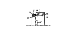
図3では、緊張リング14は、少なくとも1本の緊張ネジ16によってトルクに耐えるように偏心部分12に固定されており、緊張リング14は、径方向スロット15を含み、本明細書では偏心ブッシュ13に向かって軸方向に突出しているタペットEを支持している。緊張ネジ16を緩めると、緊張リング14はタペットEと共に偏心部分12(又は偏心軸W)に対して周方向に回転でき、緊張ネジ16を締め付けるとトルクに耐えるように固定できる。図3では、タペットEは事前選定領域18に係合しているが、事前選定領域18はタペットEの周方向延伸部に延在する凹形状の偏心ブッシュ13の環状延伸部17として例示されている。任意ではあるが、少なくとも1つの更なる事前選定領域18’を、事前選定領域18に対して周方向にオフセットして設け、タペットEが、領域18’で、例えば図3の緩めた緊張リング14を左にシフトしてから回転させ、再び右にシフトさせることで、選択することができる。少なくとも1つの更なる事前選定領域(図示せず)を設けることも考えられる。複数の事前選定領域18、18’の場合は、これらの領域は、同じ又は異なる周方向延在部を有することができる。タペットEと事前選定領域18、18’の位置は、偏心軸Wと偏心ブッシュ13とで入れ替えることができる。
In FIG. 3, the
図4から、どちらに回転するかで偏心軸Wと共に回転するタペットEの所定タペット停止位置P1、P2を定める2つのエンドストップ19、20を各事前選定領域18が形成することが分かる。摩擦抵抗及び締め固め抵抗又は慣性によって調整されるコネクティングロッド2での偏心ブッシュ13の回転抵抗が、タペットEを、例えば位置P1から、偏心ブッシュ13を選択した回転方向でトルクに耐えるように偏心軸Wと結合させる位置P2に動かすため、位置P1、P2間の変化は、偏心軸Wの回転方向を反転させるだけで行なうことができる。回転方向を反転(図5の両矢印)させて偏心ブッシュ13と偏心軸Wとの間の相対回転位置を変化させることで、タンパバー1の有効なストロークが、例えば、薄い舗装厚さに関しては4.0mmから2.0mmに、又は厚い舗装厚さに関しては8.0mmから4.0mmに変更できる。
It can be seen from FIG. 4 that each
回転方向を反転させて調整可能な2ストローク間で、より大きなあるいはより小さなストローク差が必要な場合、エンドストップ19、20間の周方向距離の長短によるので、
事前選定領域18に対して周方向にオフセットした少なくとも1つの更なる事前選定領域18’が適当なこともある。図5で示されるように、支持体(緊張リング14)付タペットEは、偏心軸Wの偏心部分12である所望する相対回転位置まで回転させて事前選定できるので、1つの事前選定領域18を提供するだけで十分かも知れない。
If a larger or smaller stroke difference is required between two adjustable strokes by reversing the rotation direction, it depends on the length of the circumferential distance between the end stops 19 and 20.
At least one
図3〜図5では、各事前選定領域18又は18’は、偏心ブッシュ13及び偏心部分12のタペットE又は緊張リング14に設けられている。これらの位置は入れ替えてもよい。また、複数のタペットEを緊張リング14に周方向にオフセットして設け、タペットが、事前選定領域18、18’で選択的に係合可能にし、任意ではあるが周方向に異なる寸法とすることも考えられる。
3-5, each preselected
図6の実施形態では、タペットEをピン又は調整バネ23とし、ピン又はバネを、例えば着脱可能に、偏心部分12の溝24に挿入して、他方の事前選定領域18’と係合するように移動可能にする。別の方法としては、複数の溝24を設け、溝を偏心部分12の周方向に分布させて、各溝にタペットEを任意に挿入してもよい。
In the embodiment of FIG. 6, the tappet E is a pin or
図7の実施形態では、タペットEを、偏心部分12の長手方向に連続する溝24に圧入、又は挿脱自在に挿入する長い調整バネ23としている。
In the embodiment of FIG. 7, the tappet E is a
図8の実施形態では、タペットEを摺動リング26の形にしており、タペットを、例えば、周方向歯25によって、トルクに耐えるように偏心部分12に接続し、また、ボールキャッチ27のキャッチ力に対して図8では左に変位させて、必要に応じて、他の事前選定領域18’にタペットEを係合できる。
In the embodiment of FIG. 8, the tappet E is in the form of a sliding
図9の実施形態では、タペットEを、偏心ブッシュ13の窪み29に着脱可能に固定されるネジ28とし、ネジを、本明細書では偏心部分12に形成した選択領域18(偏心部分12に設けられた周方向に限定されている周溝30)に係合させる。周溝30により、例えばエンドストップ20を形成する。周方向に周溝30より短い又は長い更なる事前選定領域18’を、例えば、偏心部分12の径方向の面に設けて、ネジ28を緩めた後にそこにタペットEを係合させることができる。
In the embodiment of FIG. 9, the tappet E is a
図5に類似する図10の実施形態では、事前選定領域18が、偏心ブッシュ13の環状フランジ17にある、又は直接偏心ブッシュ13にある凹部となっている。タペットEは、偏心軸Wの偏心部分12にある溝31に、径方向の力33によって再調整バネ32の力に対しシフトするプランジャ30に設けられている。タペットEを別の事前選定領域18’に移動させるために、プランジャ30を押圧した後に、例えば偏心ブッシュ13を、他の事前選定領域18’に係合するまで、回転させる。
In the embodiment of FIG. 10 similar to FIG. 5, the preselected
図11の実施形態では、タペットEがスライド33に配置され、スライドは蟻継ぎに類似する偏心部分12の溝34内で軸方向に移動でき、スライドと接触する再調整バネ35がスライドを図示した係合位置に至らせるよう作用する。軸方向の圧力(矢印36)によって、タペットEを、1事前選定領域18から選択的に解除して、偏心ブッシュ13を回転させた後に、別の事前選定領域18’に係合させることができる。
In the embodiment of FIG. 11, a tappet E is placed on the
スクリードはそれぞれ別々の駆動モータを有する複数のタンパTを備えることができるので、駆動モータ、例えば油圧モータを例えば並列又は直列に接続し、集中的に回転方向の反転を行わせるのが妥当である。変換ギアを設けた場合、これらを並列に接続するとともに、切替可能にして、各事前選定領域18、18’で定められた範囲内でタンパバー1のストロークを変更すべきである。
Since the screed can be provided with a plurality of tampers T each having a separate drive motor, it is reasonable to connect the drive motors, for example, hydraulic motors, for example, in parallel or in series so that the rotation direction is intensively reversed. . When the conversion gears are provided, they should be connected in parallel and switched so that the stroke of the
図示していない別の方法では、各駆動モータMを偏心軸Wに直接作動するようにしてもよい。 In another method not shown, each drive motor M may be operated directly on the eccentric shaft W.
回転方向の反転については、機械オペレータ又はオペレータらがスクリードの外部コントロールスタンドで実行できる。特に適切には、各敷設パラメタを知って考慮し、例えば敷設速度及び/又は舗装厚さが変更された場合に、回転方向の反転を示唆させる、又は敷設操作開始時に反転させてタンパバー1のストロークを変更された敷設条件に適応するように、回転方向の向きを自動制御する。回転方向の反転は、好適には、敷設操作の停止中に行なう。
The reversal of the direction of rotation can be performed by a machine operator or operators at the screed's external control stand. It is particularly appropriate to know and take into account each laying parameter, for example if the laying speed and / or pavement thickness is changed, suggesting a reversal of the direction of rotation, or reversing at the start of the laying operation and the stroke of the
Claims (10)
前記偏心ブッシュは、タンパバー(1)をストローク運動で駆動するコネクティングロッド(2)内に回転可能に取付けられ、前記タンパバー(1)の前記ストロークは、前記偏心ブッシュ(13)と前記偏心部分(12)との間における相対的な回転位置を周方向領域内で調整することで可変であり、各相対的な回転位置決めが、タンパバーストロークの半分を定めるようになっている道路仕上げ機のスクリード(B)のタンパ(T)であって、
少なくとも1つのタペット(E)と、前記タペットに関連する少なくとも1つの事前選定領域(18、18’)とが、前記偏心軸(W)と前記偏心ブッシュ(13)との間に設けられ、
前記事前選定領域(18、18’)は、前記タペット(E)の2つのエンドストップ(19、20)により制限され、前記エンドストップ(19、20)間の前記周方向距離は、前記周方向距離に見られる前記タペット(E)の延在部より長く、
前記事前選定領域(18、18’)又は前記タペット(E)は、前記偏心軸(W)若しくは前記偏心軸(W)内に、あるいは前記偏心ブッシュ(13)若しくは前記偏心ブッシュ(13)内に形成されており、
前記偏心軸(W)の駆動装置として、回転方向を反転できる油圧又は電気モータ(M)、又は固定回転方向で回転し変換ギアを有する油圧又は電気モータが設けられており、
前記タペット(E)は、工具無しで、片方の停止位置から他方の停止位置まで、前記駆動装置を用いて前記偏心軸(W)の回転方向(21)を反転させて調整され、前記回転方向(21)の反転後に有効な前記偏心軸(W)の回転方向で、前記タペット(E)を前記停止位置(P1又はP2)に保持できること、
を特徴とするタンパ。 An eccentric shaft (W), which is rotatably driven by a drive device, with at least one eccentric part (12) and supported by said eccentric part (12) to withstand torque at at least one stop position (P1, P2) An eccentric bushing (13),
The eccentric bush is rotatably mounted in a connecting rod (2) that drives the tamper bar (1) by a stroke motion, and the stroke of the tamper bar (1) includes the eccentric bush (13) and the eccentric portion (12). ) And the relative rotational position in the circumferential region is variable, and each relative rotational positioning is defined as half the tamper bar stroke. B) tamper (T),
At least one tappet (E) and at least one preselected region (18, 18 ′) associated with the tappet are provided between the eccentric shaft (W) and the eccentric bush (13);
The preselected area (18, 18 ′) is limited by two end stops (19, 20) of the tappet (E), and the circumferential distance between the end stops (19, 20) is Longer than the extension of the tappet (E) seen in the directional distance,
The pre-selected region (18, 18 ') or the tappet (E) is in the eccentric shaft (W) or the eccentric shaft (W), or in the eccentric bush (13) or the eccentric bush (13). Is formed,
As the drive device for the eccentric shaft (W), a hydraulic or electric motor (M) that can reverse the rotation direction, or a hydraulic or electric motor that rotates in a fixed rotation direction and has a conversion gear is provided.
The tappet (E) is adjusted by reversing the rotation direction (21) of the eccentric shaft (W) from the one stop position to the other stop position without using a tool, using the drive device, The tappet (E) can be held at the stop position (P1 or P2) in the rotational direction of the eccentric shaft (W) effective after the reversal of (21),
A tamper characterized by
Applications Claiming Priority (2)
| Application Number | Priority Date | Filing Date | Title |
|---|---|---|---|
| EP09014515A EP2325391B1 (en) | 2009-11-20 | 2009-11-20 | Tamper with variable stroke |
| EP09014515.2 | 2009-11-20 |
Publications (2)
| Publication Number | Publication Date |
|---|---|
| JP2011106263A true JP2011106263A (en) | 2011-06-02 |
| JP5255620B2 JP5255620B2 (en) | 2013-08-07 |
Family
ID=42132197
Family Applications (1)
| Application Number | Title | Priority Date | Filing Date |
|---|---|---|---|
| JP2010255632A Active JP5255620B2 (en) | 2009-11-20 | 2010-11-16 | Screed tamper on road finishing machine |
Country Status (5)
| Country | Link |
|---|---|
| US (1) | US8534955B2 (en) |
| EP (1) | EP2325391B1 (en) |
| JP (1) | JP5255620B2 (en) |
| CN (1) | CN102071634B (en) |
| PL (1) | PL2325391T3 (en) |
Cited By (1)
| Publication number | Priority date | Publication date | Assignee | Title |
|---|---|---|---|---|
| JP2015148134A (en) * | 2014-02-07 | 2015-08-20 | ヨゼフ フェゲーレ アーゲー | temper |
Families Citing this family (16)
| Publication number | Priority date | Publication date | Assignee | Title |
|---|---|---|---|---|
| PL2325392T3 (en) * | 2009-11-20 | 2021-05-31 | Joseph Vögele AG | Method for laying a road paving and paving screed |
| PL2366832T3 (en) * | 2010-03-18 | 2016-03-31 | Voegele Ag J | Method and paver for producing a compacted paved surface |
| DE102011119938A1 (en) * | 2011-12-01 | 2013-06-06 | Bomag Gmbh | Method and device for the stroke adjustment of a tamping strip of a road paver |
| US8371770B1 (en) * | 2012-04-09 | 2013-02-12 | Caterpillar Inc. | Apparatus for tamping paving material |
| DE102013000788A1 (en) * | 2013-01-17 | 2014-07-17 | Bomag Gmbh | Screed for road finisher, has drive train with spline shaft connection, which has spline shaft on base screed parallel to extension direction of extending screed and complementary longitudinally movable spline hub |
| CN103590309B (en) * | 2013-11-08 | 2015-11-25 | 中联重科股份有限公司 | For the hammer ram mechanism of paver and ironing machine and paver |
| CN103591121B (en) * | 2013-11-19 | 2016-01-20 | 无锡市铁民印刷机械有限公司 | Eccentric drive shaft |
| WO2015179988A1 (en) | 2014-05-26 | 2015-12-03 | Ammann Schweiz Ag | Method for converting a rotary movement into a translatory movement, use of same and device for carrying same out |
| DE102015016777A1 (en) | 2015-12-23 | 2017-06-29 | Bomag Gmbh | Ramming bar device of a screed, screed, paver and method for changing the stroke of a tamper strip device |
| CN109112933B (en) * | 2018-10-31 | 2024-01-23 | 徐工集团工程机械股份有限公司 | Screed vibrating mechanism and paver |
| US11078634B2 (en) * | 2019-11-05 | 2021-08-03 | Caterpillar Paving Products Inc. | Variable tamper bar amplitude for asphalt pavers |
| EP4097300A1 (en) | 2020-01-27 | 2022-12-07 | Volvo Construction Equipment AB | A tamper device for a screed of a working machine and a method for adjusting a stroke of a tamper device for a screed of a working machine |
| EP4029991B1 (en) * | 2021-01-14 | 2023-05-10 | Joseph Vögele AG | Tamper stroke adjustment |
| CN113622404A (en) * | 2021-08-27 | 2021-11-09 | 山东黄河顺成水利水电工程有限公司 | Soil tamping device for dyke reinforcement |
| CN113897842A (en) * | 2021-10-21 | 2022-01-07 | 徐工集团工程机械股份有限公司道路机械分公司 | Vibrating mechanism, screed and paver |
| CN114395958B (en) * | 2022-01-19 | 2022-09-13 | 河北通宇建筑工程有限公司 | Energy-saving scraper blade pitch material clearing device for highway pitch paver |
Citations (9)
| Publication number | Priority date | Publication date | Assignee | Title |
|---|---|---|---|---|
| JPS54102004A (en) * | 1978-01-26 | 1979-08-11 | Meiwa Seisakushiyo Kk | Device for adjusting impulsive force of tamper |
| JPS54119702A (en) * | 1978-03-10 | 1979-09-17 | Mikasa Sangiyou Kk | Vibromotive device by eccentric load |
| JPS5740006A (en) * | 1980-07-07 | 1982-03-05 | Delmag Maschinenfabrik | Crank drive mechanism for retaining wall apparatus |
| JPS5771536U (en) * | 1980-10-20 | 1982-05-01 | ||
| JPH07197415A (en) * | 1993-12-28 | 1995-08-01 | Sakai Jukogyo Kk | Vibration exciting method of vibration roller and device thereof |
| JPH1060813A (en) * | 1996-06-22 | 1998-03-03 | Abg Allgemeine Baumas Gmbh | Paving method with asphalt mixture |
| JPH11217805A (en) * | 1998-02-02 | 1999-08-10 | Ekusen Kk | Progressive direction switching device of vibration tamping machine |
| JP2006009458A (en) * | 2004-06-28 | 2006-01-12 | Dajin Machinery (Shanghai) Co Ltd | Oscillating type rolling machine |
| JP2007120198A (en) * | 2005-10-28 | 2007-05-17 | Sumitomo (Shi) Construction Machinery Manufacturing Co Ltd | Hydraulic circuit of compaction device |
Family Cites Families (11)
| Publication number | Priority date | Publication date | Assignee | Title |
|---|---|---|---|---|
| GB742141A (en) | 1953-05-13 | 1955-12-21 | Hordern Mason & Edwards Ltd | Improvements relating to adjustable throw cranks |
| GB760725A (en) | 1954-01-30 | 1956-11-07 | Hordern Mason & Edwards Ltd | Improvements relating to variable throw cranks |
| DE3127377C2 (en) | 1981-07-09 | 1985-05-02 | LIBA Lingener Baumaschinen Gesellschaft mbH & Co. KG, 4450 Lingen | Compaction screed for road pavers |
| DE3933742A1 (en) * | 1988-12-19 | 1990-06-21 | Dynapac Gmbh | COMPaction screed for a road paver |
| CN2273330Y (en) * | 1995-04-14 | 1998-01-28 | 山东省青州市公路局 | Automatic tamper |
| CN2353788Y (en) * | 1998-11-09 | 1999-12-15 | 刘庆范 | Multifunction concrete-spreading machine |
| SE513571C2 (en) * | 1999-03-18 | 2000-10-02 | Ulf Bertil Andersson | Apparatus for generating mechanical vibrations |
| US6457902B1 (en) * | 2001-03-20 | 2002-10-01 | Wacker Corporation | Truss screed with covered vibrator shaft |
| CN2775113Y (en) * | 2005-03-02 | 2006-04-26 | 武汉科技大学 | Driving type vibration road rolling beater |
| DE202005006059U1 (en) | 2005-04-15 | 2005-06-23 | MTS Gesellschaft für Maschinentechnik und Sonderbauten mbH | Cultivation compressor with adjustable exciter mass |
| DE102008050576A1 (en) * | 2008-10-06 | 2010-04-08 | Bomag Gmbh | Device for generating a circular oscillation or a directed oscillation with continuously adjustable oscillation amplitude or exciter force |
-
2009
- 2009-11-20 EP EP09014515A patent/EP2325391B1/en active Active
- 2009-11-20 PL PL09014515T patent/PL2325391T3/en unknown
-
2010
- 2010-11-11 US US12/944,435 patent/US8534955B2/en active Active
- 2010-11-16 JP JP2010255632A patent/JP5255620B2/en active Active
- 2010-11-19 CN CN201010550813XA patent/CN102071634B/en active Active
Patent Citations (9)
| Publication number | Priority date | Publication date | Assignee | Title |
|---|---|---|---|---|
| JPS54102004A (en) * | 1978-01-26 | 1979-08-11 | Meiwa Seisakushiyo Kk | Device for adjusting impulsive force of tamper |
| JPS54119702A (en) * | 1978-03-10 | 1979-09-17 | Mikasa Sangiyou Kk | Vibromotive device by eccentric load |
| JPS5740006A (en) * | 1980-07-07 | 1982-03-05 | Delmag Maschinenfabrik | Crank drive mechanism for retaining wall apparatus |
| JPS5771536U (en) * | 1980-10-20 | 1982-05-01 | ||
| JPH07197415A (en) * | 1993-12-28 | 1995-08-01 | Sakai Jukogyo Kk | Vibration exciting method of vibration roller and device thereof |
| JPH1060813A (en) * | 1996-06-22 | 1998-03-03 | Abg Allgemeine Baumas Gmbh | Paving method with asphalt mixture |
| JPH11217805A (en) * | 1998-02-02 | 1999-08-10 | Ekusen Kk | Progressive direction switching device of vibration tamping machine |
| JP2006009458A (en) * | 2004-06-28 | 2006-01-12 | Dajin Machinery (Shanghai) Co Ltd | Oscillating type rolling machine |
| JP2007120198A (en) * | 2005-10-28 | 2007-05-17 | Sumitomo (Shi) Construction Machinery Manufacturing Co Ltd | Hydraulic circuit of compaction device |
Cited By (2)
| Publication number | Priority date | Publication date | Assignee | Title |
|---|---|---|---|---|
| JP2015148134A (en) * | 2014-02-07 | 2015-08-20 | ヨゼフ フェゲーレ アーゲー | temper |
| US9487924B2 (en) | 2014-02-07 | 2016-11-08 | Joseph Voegele Ag | Tamper |
Also Published As
| Publication number | Publication date |
|---|---|
| US20110123270A1 (en) | 2011-05-26 |
| CN102071634A (en) | 2011-05-25 |
| PL2325391T3 (en) | 2013-08-30 |
| JP5255620B2 (en) | 2013-08-07 |
| US8534955B2 (en) | 2013-09-17 |
| CN102071634B (en) | 2013-06-26 |
| EP2325391A1 (en) | 2011-05-25 |
| EP2325391B1 (en) | 2013-03-20 |
Similar Documents
| Publication | Publication Date | Title |
|---|---|---|
| JP5255620B2 (en) | Screed tamper on road finishing machine | |
| US9790648B2 (en) | Method for laying down a pavement, a screed and a road paver | |
| CN102182135B (en) | Vibratory system for a compactor | |
| CN103132440B (en) | For regulating method and the equipment of the amplitude making beam firm by ramming of pavement recondition machine | |
| US8206061B1 (en) | Eccentric vibratory weight shaft for utility compactor | |
| JP6738420B2 (en) | Tamping unit for tamping tracks and method for tamping tracks | |
| CN103764916B (en) | For being transmitted device and the compacting machine of linear load by High Rotation Speed component | |
| US8967910B2 (en) | Eccentric weight shaft for vibratory compactor | |
| CN100418645C (en) | Regulator for regulating accentric moment or foller drum eccentric shaft | |
| JP2013117161A (en) | Device for adjusting stroke of tamping beam of road finishing device | |
| CZ2012173A3 (en) | Vibration system for soil compacting earth moving machine and earth moving machine provided with such a vibration system and co | |
| US9103077B2 (en) | Vibratory mechanism including double helical key shaft, compactor including vibratory mechanism, and method of operating a vibratory mechanism | |
| JP2000337181A (en) | Functional drive unit for positioning regualting means | |
| US5988297A (en) | Variable eccentric vibratory hammer | |
| US20230083709A1 (en) | Tamper device for a screed of a working machine and a method for adjusting a stroke of a tamper device for a screed of a working machine | |
| EP2242590B1 (en) | Unbalance exciter with one or more rotatable unbalances | |
| GB1569648A (en) | Screed board for concrete road finishers | |
| DE4022089A1 (en) | Casting concrete pipes by vibration process - uses cylindrical mould with vibrators mounted inside mould core | |
| CN115023520B (en) | Tamping device for a working machine screed and method for adjusting the stroke of a tamping device for a working machine screed | |
| DE202004014585U1 (en) | Vibration exciter for e.g. compaction roller, has imbalance mass arranged on pivoted imbalance-shaft and force transmission unit moving imbalance mass, such that angular speed of imbalance mass is varied during each revolution |
Legal Events
| Date | Code | Title | Description |
|---|---|---|---|
| A977 | Report on retrieval |
Free format text: JAPANESE INTERMEDIATE CODE: A971007 Effective date: 20120709 |
|
| A131 | Notification of reasons for refusal |
Free format text: JAPANESE INTERMEDIATE CODE: A131 Effective date: 20120904 |
|
| A521 | Request for written amendment filed |
Free format text: JAPANESE INTERMEDIATE CODE: A523 Effective date: 20121128 |
|
| TRDD | Decision of grant or rejection written | ||
| A01 | Written decision to grant a patent or to grant a registration (utility model) |
Free format text: JAPANESE INTERMEDIATE CODE: A01 Effective date: 20130402 |
|
| A61 | First payment of annual fees (during grant procedure) |
Free format text: JAPANESE INTERMEDIATE CODE: A61 Effective date: 20130419 |
|
| R150 | Certificate of patent or registration of utility model |
Ref document number: 5255620 Country of ref document: JP Free format text: JAPANESE INTERMEDIATE CODE: R150 Free format text: JAPANESE INTERMEDIATE CODE: R150 |
|
| FPAY | Renewal fee payment (event date is renewal date of database) |
Free format text: PAYMENT UNTIL: 20160426 Year of fee payment: 3 |
|
| R250 | Receipt of annual fees |
Free format text: JAPANESE INTERMEDIATE CODE: R250 |
|
| R250 | Receipt of annual fees |
Free format text: JAPANESE INTERMEDIATE CODE: R250 |
|
| R250 | Receipt of annual fees |
Free format text: JAPANESE INTERMEDIATE CODE: R250 |
|
| R250 | Receipt of annual fees |
Free format text: JAPANESE INTERMEDIATE CODE: R250 |
|
| R250 | Receipt of annual fees |
Free format text: JAPANESE INTERMEDIATE CODE: R250 |
|
| R250 | Receipt of annual fees |
Free format text: JAPANESE INTERMEDIATE CODE: R250 |
|
| R250 | Receipt of annual fees |
Free format text: JAPANESE INTERMEDIATE CODE: R250 |
|
| R250 | Receipt of annual fees |
Free format text: JAPANESE INTERMEDIATE CODE: R250 |