JP2011102473A - Method of repairing directly connected track - Google Patents
Method of repairing directly connected track Download PDFInfo
- Publication number
- JP2011102473A JP2011102473A JP2009257107A JP2009257107A JP2011102473A JP 2011102473 A JP2011102473 A JP 2011102473A JP 2009257107 A JP2009257107 A JP 2009257107A JP 2009257107 A JP2009257107 A JP 2009257107A JP 2011102473 A JP2011102473 A JP 2011102473A
- Authority
- JP
- Japan
- Prior art keywords
- rail
- shoulder
- concrete roadbed
- fastening
- base portion
- Prior art date
- Legal status (The legal status is an assumption and is not a legal conclusion. Google has not performed a legal analysis and makes no representation as to the accuracy of the status listed.)
- Granted
Links
- 238000000034 method Methods 0.000 title claims abstract description 38
- 230000008439 repair process Effects 0.000 claims abstract description 61
- 238000005520 cutting process Methods 0.000 claims abstract description 22
- 238000009434 installation Methods 0.000 claims description 13
- 238000003825 pressing Methods 0.000 claims description 11
- 230000008878 coupling Effects 0.000 claims 2
- 238000010168 coupling process Methods 0.000 claims 2
- 238000005859 coupling reaction Methods 0.000 claims 2
- 230000004308 accommodation Effects 0.000 claims 1
- 241001669679 Eleotris Species 0.000 abstract description 57
- 238000011900 installation process Methods 0.000 abstract description 4
- 239000012212 insulator Substances 0.000 description 19
- 238000005452 bending Methods 0.000 description 7
- 239000000945 filler Substances 0.000 description 7
- 238000003780 insertion Methods 0.000 description 3
- 230000037431 insertion Effects 0.000 description 3
- 239000000463 material Substances 0.000 description 3
- 230000002093 peripheral effect Effects 0.000 description 3
- 239000011347 resin Substances 0.000 description 3
- 229920005989 resin Polymers 0.000 description 3
- XEEYBQQBJWHFJM-UHFFFAOYSA-N Iron Chemical compound [Fe] XEEYBQQBJWHFJM-UHFFFAOYSA-N 0.000 description 2
- 229910000639 Spring steel Inorganic materials 0.000 description 2
- 230000003187 abdominal effect Effects 0.000 description 2
- 239000004568 cement Substances 0.000 description 2
- 238000010586 diagram Methods 0.000 description 2
- 230000000694 effects Effects 0.000 description 2
- 239000011810 insulating material Substances 0.000 description 2
- 230000000149 penetrating effect Effects 0.000 description 2
- 238000004804 winding Methods 0.000 description 2
- 230000015572 biosynthetic process Effects 0.000 description 1
- 238000010276 construction Methods 0.000 description 1
- 238000005553 drilling Methods 0.000 description 1
- 238000007689 inspection Methods 0.000 description 1
- 238000009413 insulation Methods 0.000 description 1
- 229910052742 iron Inorganic materials 0.000 description 1
- 238000012423 maintenance Methods 0.000 description 1
- 238000004519 manufacturing process Methods 0.000 description 1
- 238000012986 modification Methods 0.000 description 1
- 230000004048 modification Effects 0.000 description 1
- 238000003860 storage Methods 0.000 description 1
Images


Landscapes
- Machines For Laying And Maintaining Railways (AREA)
Abstract
【課題】作業スペースの小さい場所等であっても、効率的かつ低コストで補修作業を行うことができる直結系軌道の補修方法の提供を目的とする。
【解決手段】第1締結装置12のショルダー21からレール13及びクリップ23を取り外す撤去工程と、ショルダー21におけるまくらぎ11からの突出部分(ショルダー本体24)を切断する切断工程と、まくらぎ11上に第2締結装置を設置する設置工程と、第2締結装置によってレール13を締結する締結工程とを有することを特徴とする。
【選択図】図3An object of the present invention is to provide a repair method for a directly connected track that can perform repair work efficiently and at low cost even in a small work space.
A removal step of removing a rail 13 and a clip 23 from a shoulder 21 of a first fastening device 12, a cutting step of cutting a protruding portion (shoulder body 24) from the sleeper 11 in the shoulder 21, and the upper portion of the sleeper 11 It has the installation process which installs a 2nd fastening apparatus, and the fastening process which fastens the rail 13 with a 2nd fastening apparatus, It is characterized by the above-mentioned.
[Selection] Figure 3
Description
本発明は、直結系軌道の補修方法に関する。 The present invention relates to a method for repairing a directly connected track.
近年、鉄道の軌道では、補修頻度の削減や作業効率の向上、作業コストの低下等を図るために省力化軌道の開発が進められている。この省力化軌道としては、例えばTC型省力化軌道のような直結系軌道が知られている。TC型省力化軌道とは、従来のバラスト軌道に代わって、レールが載置されるまくらぎの下部及び周辺部のバラストをセメント等の填充材により固結してまくらぎとバラストとを一体化し、填充層(コンクリート道床)として構成したものである。TC型省力化軌道のまくらぎには、締結装置が埋設されており、この締結装置によってレールを締結することで、まくらぎ上にレールが固定されるようになっている。 In recent years, on railway tracks, labor-saving tracks have been developed in order to reduce the frequency of repairs, improve work efficiency, and reduce work costs. As this labor-saving track, for example, a directly-connected track such as a TC-type labor-saving track is known. TC-type labor-saving track means that instead of the conventional ballast track, the lower and peripheral ballasts on which the rails are placed are consolidated with a filler such as cement to integrate the sleeper and ballast. It is configured as a filling layer (concrete roadbed). A fastening device is embedded in the sleeper of the TC-type labor-saving track, and the rail is fixed on the sleeper by fastening the rail with this fastening device.
ここで、上述した締結装置としては、座面式のパンドロール締結装置が知られている。この締結装置は、例えば特許文献1に示されるように、まくらぎにショルダーが埋設されており、このショルダーとレールとの間にクリップを介在させることで、レールをまくらぎに向けて弾性的に押圧固定するようになっている。この構成によれば、クリップを装着するだけでレールを締結することができるので、メンテナンスや検査等が容易になるとされている。 Here, as the above-described fastening device, a seating surface type roll roll fastening device is known. In this fastening device, for example, as shown in Patent Document 1, a shoulder is embedded in the sleeper, and a clip is interposed between the shoulder and the rail so that the rail is elastically directed toward the sleeper. It is designed to be pressed and fixed. According to this configuration, since the rail can be fastened only by attaching the clip, it is said that maintenance, inspection, and the like are facilitated.
ところで、比較的路盤が軟らかい箇所等にTC型省力化軌道を敷設した場合、路盤が変状して填充層が沈下してしまうという問題がある。この場合、従来のバラスト軌道にあっては、まくらぎの周囲や下部にバラストを新たに追加したり、バラストを交換したりすることで軌道の補修作業を行うことができるが、TC型省力化軌道のような直結系軌道にあっては、まくらぎとバラストとが填充層として一体化されているため、従来の補修作業では対応できないという問題がある。 By the way, when a TC type labor-saving track is laid in a place where the roadbed is relatively soft, there is a problem that the roadbed is deformed and the filling layer sinks. In this case, the conventional ballast track can be repaired by adding new ballast around the sleeper or by replacing the ballast, but the TC type labor-saving track In such a direct connection type track, the sleeper and the ballast are integrated as a filling layer, and therefore there is a problem that conventional repair work cannot be used.
ここで、TC型省力化軌道に補修作業を実施する場合には、填充層の周囲を掘削した後、填充層を路盤に対してジャッキアップすることで、填充層と路盤との間に空間を形成し、この空間内に再度填充材を填充することが考えられる。
しかしながら、上述した補修方法では、特に軌道の周囲にホームや排水設備等の支障物が配置されている箇所では、填充層を掘削する掘削機を侵入させるスペースを確保することが難しく、上述の方法では施工できないという問題がある。
Here, when carrying out repair work on the TC type labor-saving track, after excavating around the filling layer, jack up the filling layer with respect to the roadbed, so that there is a space between the filling layer and the roadbed. It is conceivable to form and refill the space in this space.
However, in the repair method described above, it is difficult to secure a space for the excavator to excavate the filling layer, particularly in places where obstacles such as platforms and drainage facilities are arranged around the track. Then there is a problem that construction is not possible.
本発明は、上述した事情に鑑みてなされたものであって、作業スペースの小さい場所等であっても、効率的かつ低コストで補修作業を行うことができる直結系軌道の補修方法の提供を目的とするものである。 The present invention has been made in view of the above-described circumstances, and provides a repair method for a directly connected track that can perform repair work efficiently and at low cost even in a small work space or the like. It is the purpose.
上記課題を解決するために、本発明の軌道の補修方法は、レールを支持するコンクリート道床と、前記コンクリート道床に設置され、前記レールの幅方向両側において一部が前記コンクリート道床に埋設された一対の第1ショルダー、及び第1ショルダーに装着され、前記レールの底部を前記コンクリート道床に向けて押圧する第1締結手段を有する第1締結装置と、を備えた直結系軌道の補修方法であって、前記第1ショルダーから前記レール及び前記第1締結手段を取り外す撤去工程と、前記第1ショルダーにおける前記コンクリート道床からの突出部分を切断する切断工程と、前記コンクリート道床上に第2締結装置を設置する設置工程と、前記第2締結装置によって前記レールを締結する締結工程とを有し、前記第2締結装置として、前記コンクリート道床と前記レールとの間に配置され、高さ調整に応じた厚さを有するベース部と、前記ベース部上における前記レールの幅方向両側に形成された一対の第2ショルダーと、前記第2ショルダーに装着され、前記レールの底部を前記ベース部に向けて押圧する第2締結手段とを備えるものを使用し、前記設置工程では、前記コンクリート道床上に前記ベース部及び前記一対の第2ショルダーを設置し、前記締結工程では、前記ベース部に前記レールを設置した後に、前記第2ショルダーに前記第2締結手段を装着することで前記レールの底部を前記ベース部に向けて押圧させることを特徴とする。 In order to solve the above problems, a track repair method according to the present invention includes a concrete road bed that supports a rail, and a pair of rails installed on the concrete road bed and partially embedded in the concrete road bed on both sides in the width direction of the rail. And a first fastening device having a first fastening device attached to the first shoulder and having a first fastening means for pressing the bottom of the rail toward the concrete roadbed. A removal step of removing the rail and the first fastening means from the first shoulder, a cutting step of cutting a protruding portion of the first shoulder from the concrete roadbed, and a second fastening device installed on the concrete roadbed And a fastening step of fastening the rail by the second fastening device, and as the second fastening device A base portion disposed between the concrete roadbed and the rail and having a thickness corresponding to a height adjustment; a pair of second shoulders formed on both sides of the rail in the width direction on the base portion; And a second fastening means that is attached to the second shoulder and that presses the bottom of the rail toward the base, and in the installation step, the base and the pair of second 2 shoulders are installed, and in the fastening step, after the rails are installed on the base part, the second fastening means is attached to the second shoulders to press the bottom part of the rails toward the base part. It is characterized by that.
この構成によれば、直結系軌道の補修作業時において第1ショルダーを切断した後、コンクリート道床上に第2締結装置をセットすることで、第1締結装置によってレールを締結する場合に比べて、コンクリート道床の上面からレール上端面までの高さをベース部の厚さ分だけ上昇させることができる。すなわち、路盤の変状等によってコンクリート道床が沈下した場合に、この沈下量をベース部の厚さにより許容することができる。よって、コンクリート道床上に第2締結装置をセットするだけの簡単な作業で軌道の補修作業を完了させることができる。これにより、TC型省力化軌道のような直結系軌道であっても、軌道の補修作業時にコンクリート道床の周囲を掘削する等の必要がないので、作業効率の向上を図るとともに、作業コストの低減を図ることができる。
特に、軌道の補修作業時において比較的省スペースで補修作業を行うことができるので、軌道の周囲に支障物が配置されている箇所であっても、スムーズな補修作業を実現することができる。
According to this configuration, after cutting the first shoulder at the time of repair work of the direct connection system track, by setting the second fastening device on the concrete roadbed, compared to the case where the rail is fastened by the first fastening device, The height from the upper surface of the concrete roadbed to the upper end surface of the rail can be increased by the thickness of the base portion. That is, when the concrete roadbed sinks due to deformation of the roadbed or the like, this sinking amount can be allowed by the thickness of the base portion. Therefore, the track repair work can be completed with a simple work of simply setting the second fastening device on the concrete roadbed. This makes it possible to improve work efficiency and reduce work costs because there is no need to dig around the concrete roadbed during track repair work, even for directly connected tracks such as the TC labor-saving track. Can be achieved.
In particular, since the repair work can be performed in a relatively space-saving manner during the track repair work, a smooth repair work can be realized even at locations where obstacles are arranged around the track.
また、本発明の軌道の補修方法では、前記設置工程では、前記ベース部と前記コンクリート道床との間に絶縁板を配置し、前記絶縁板における前記コンクリート道床との対向面には、前記切断工程において残存する前記第1ショルダーの一部を収容する収容部が形成されていることを特徴とする。
この構成によれば、第1ショルダーの一部がコンクリート道床から僅かに突出して残存している場合であっても、この残存した部分を収容部によって収容することで絶縁板をコンクリート道床上にガタツキなく載置することができる。したがって、絶縁板上に配置される第2締結装置のベース部のガタツキも防止することができる。
また、第1ショルダーの一部をコンクリート道床から僅かに突出して残存させることで、第1ショルダーの切断面をコンクリート道床と面一に切断する場合に比べて、第1ショルダーの切断時に高い切断精度を要求されないため、作業効率の向上を図ることができる。さらに、切断時にコンクリート道床を損傷させる虞もない。
In the track repair method of the present invention, in the installation step, an insulating plate is disposed between the base portion and the concrete roadbed, and the cutting step is performed on a surface of the insulating plate facing the concrete roadbed. A housing portion is formed for housing a part of the first shoulder remaining in step.
According to this configuration, even if a part of the first shoulder protrudes slightly from the concrete roadbed and remains, the insulating plate is rattled on the concrete roadbed by storing the remaining part by the storage unit. It can be mounted without. Therefore, the backlash of the base part of the 2nd fastening apparatus arrange | positioned on an insulating board can also be prevented.
Also, by leaving a part of the first shoulder to protrude slightly from the concrete roadbed, the cutting accuracy of the first shoulder is higher than when cutting the first shoulder with the concrete roadbed. Therefore, work efficiency can be improved. Furthermore, there is no risk of damaging the concrete roadbed during cutting.
また、本発明の軌道の補修方法では、レールを支持するコンクリート道床と、前記コンクリート道床上に設置され、前記レールの幅方向両側において一部が前記コンクリート道床に埋設された一対の第1ショルダー、及び第1ショルダーに装着され、前記レールの底部を前記コンクリート道床に向けて押圧する第1締結手段とを有する第1締結装置と、を備えた直結系軌道の補修方法であって、前記第1ショルダーから前記レール及び前記第1締結手段を取り外す撤去工程と、前記コンクリート道床上に第2締結装置を設置する設置工程と、前記第2締結装置によって前記レールを締結する締結工程とを有し、前記第2締結装置として、前記コンクリート道床と前記レールとの間に配置され、高さ調整に応じた厚さを有するベース部と、前記ベース部上における前記レールの幅方向両側に形成された一対の第2ショルダーと、前記第2ショルダーに装着され、前記レールの底部を前記ベース部に向けて押圧する第2締結手段とを備え、前記ベース部に、前記第1ショルダーにおける前記コンクリート道床からの突出部分を避ける逃げ部が形成されたものを使用し、前記設置工程では、前記第1ショルダーにおける前記コンクリート道床からの突出部分と前記逃げ部とを重ね合わせた状態で、前記コンクリート道床上に前記ベース部及び前記一対の第2ショルダーを設置し、前記締結工程では、前記ベース部に前記レールを設置した後に、前記第2ショルダーに前記第2締結手段を装着することで前記レールの底部を前記ベース部に向けて押圧させることを特徴とする。
この構成によれば、直結系軌道の補修作業時において第1ショルダーを切断した後、コンクリート道床上に第2締結装置をセットすることで、第1締結装置によってレールを締結する場合に比べて、コンクリート道床の上面からレール上端面までの高さをベース部の厚さ分だけ上昇させることができる。すなわち、路盤の変状等によってコンクリート道床が沈下した場合に、この沈下量をベース部の厚さにより許容することができる。よって、コンクリート道床上に第2締結装置をセットするだけの簡単な作業で軌道の補修作業を完了させることができる。これにより、TC型省力化軌道のような直結系軌道であっても、軌道の補修作業時にコンクリート道床の周囲を掘削する等の必要がないので、作業効率の向上を図るとともに、作業コストの低減を図ることができる。
特に、軌道の補修作業時において比較的省スペースで補修作業を行うことができるので、軌道の周囲に支障物が配置されている箇所であっても、スムーズな補修作業を実現することができる。
しかも、本発明の構成によれば、上述した請求項1の構成と異なり、第1ショルダーを切断することなく補修作業を行うことができるので、作業効率の更なる向上を図ることができる。
Further, in the track repair method of the present invention, a concrete road bed that supports a rail, and a pair of first shoulders that are installed on the concrete road bed and partly embedded in the concrete road bed on both sides in the width direction of the rail, And a first fastening device that is attached to the first shoulder and has a first fastening device that presses the bottom of the rail toward the concrete roadbed, and is a repair method for a directly connected system track, A removal step of removing the rail and the first fastening means from a shoulder, an installation step of installing a second fastening device on the concrete roadbed, and a fastening step of fastening the rail by the second fastening device, As the second fastening device, a base portion disposed between the concrete roadbed and the rail and having a thickness according to height adjustment; and A pair of second shoulders formed on both sides in the width direction of the rail on the base portion, and second fastening means attached to the second shoulder and pressing the bottom portion of the rail toward the base portion. The base portion is formed with a relief portion that avoids a protruding portion from the concrete roadbed in the first shoulder, and in the installation step, the protruding portion from the concrete roadbed in the first shoulder and the The base portion and the pair of second shoulders are installed on the concrete roadbed in a state where the escape portions are overlapped, and in the fastening process, after the rails are installed on the base portion, By mounting the second fastening means, the bottom of the rail is pressed toward the base.
According to this configuration, after cutting the first shoulder at the time of repair work of the direct connection system track, by setting the second fastening device on the concrete roadbed, compared to the case where the rail is fastened by the first fastening device, The height from the upper surface of the concrete roadbed to the upper end surface of the rail can be increased by the thickness of the base portion. That is, when the concrete roadbed sinks due to deformation of the roadbed or the like, this sinking amount can be allowed by the thickness of the base portion. Therefore, the track repair work can be completed with a simple work of simply setting the second fastening device on the concrete roadbed. This makes it possible to improve work efficiency and reduce work costs because there is no need to dig around the concrete roadbed during track repair work, even for directly connected tracks such as the TC labor-saving track. Can be achieved.
In particular, since the repair work can be performed in a relatively space-saving manner during the track repair work, a smooth repair work can be realized even at locations where obstacles are arranged around the track.
And according to the structure of this invention, unlike the structure of Claim 1 mentioned above, since repair work can be performed without cut | disconnecting a 1st shoulder, the further improvement of work efficiency can be aimed at.
また、本発明の軌道の補修方法では、前記第2締結装置の前記ベース部は、前記レールが載置される上段部と、前記上段部の幅方向両側に形成され、前記上段部より高さが縮小した下段部とを備え、前記設置工程では、締結部材を用いて前記下段部を前記コンクリート道床に固定することを特徴とする。
この構成によれば、ベース部に上段部よりも厚さが薄い下段部を形成することで、上段部の厚さを厚く形成した場合であっても、それに伴いコンクリート道床に締結される締結部材の長さを長くする必要がない。これにより、締結部材の長さ拡大に伴う曲げモーメントの増加を抑制することができる。
Further, in the track repairing method of the present invention, the base portion of the second fastening device is formed on an upper step portion on which the rail is placed and on both sides in the width direction of the upper step portion, and is higher than the upper step portion. And the lower step portion is fixed to the concrete roadbed using a fastening member in the installation step.
According to this structure, even if it is a case where the thickness of an upper stage part is formed thickly by forming the lower stage part thinner than an upper stage part in a base part, the fastening member fastened to a concrete roadbed in connection with it There is no need to increase the length. Thereby, the increase in the bending moment accompanying the length expansion of a fastening member can be suppressed.
本発明によれば、直結系軌道の補修作業時において第1ショルダーを切断した後、コンクリート道床上に第2締結装置をセットすることで、第1締結装置によってレールを締結する場合に比べて、コンクリート道床の上面からレール上端面までの高さをベース部の厚さ分だけ上昇させることができる。すなわち、路盤の変状等によってコンクリート道床が沈下した場合に、この沈下量をベース部の厚さにより許容することができる。よって、コンクリート道床上に第2締結装置をセットするだけの簡単な作業で軌道の補修作業を完了させることができる。これにより、TC型省力化軌道のような直結系軌道であっても、軌道の補修作業時にコンクリート道床の周囲を掘削する等の必要がないので、作業効率の向上を図るとともに、作業コストの低減を図ることができる。
特に、軌道の補修作業時において比較的省スペースで補修作業を行うことができるので、軌道の周囲に支障物が配置されている箇所であっても、スムーズな補修作業を実現することができる。
According to the present invention, after cutting the first shoulder at the time of repair work of the direct connection type track, by setting the second fastening device on the concrete roadbed, compared with the case where the rail is fastened by the first fastening device, The height from the upper surface of the concrete roadbed to the upper end surface of the rail can be increased by the thickness of the base portion. That is, when the concrete roadbed sinks due to deformation of the roadbed or the like, this sinking amount can be allowed by the thickness of the base portion. Therefore, the track repair work can be completed with a simple work of simply setting the second fastening device on the concrete roadbed. This makes it possible to improve work efficiency and reduce work costs because there is no need to dig around the concrete roadbed during track repair work, even for directly connected tracks such as the TC labor-saving track. Can be achieved.
In particular, since the repair work can be performed in a relatively space-saving manner during the track repair work, a smooth repair work can be realized even at locations where obstacles are arranged around the track.
(第1実施形態)
次に、本発明の第1実施形態を図面に基づいて説明する。本実施形態は、TC型省力化軌道の補修方法であって、路盤が変状した場合等に、座面式の締結装置が埋設されたコンクリート道床にタイプレート式の締結装置を設置するものである。そのため、以下の説明では、まず補修作業前の軌道である座面式の締結装置が設置されたTC型省力化軌道について説明する。
(First embodiment)
Next, a first embodiment of the present invention will be described with reference to the drawings. This embodiment is a TC-type labor-saving track repair method in which a tie plate type fastening device is installed on a concrete roadbed in which a seating type fastening device is embedded when a roadbed is deformed. is there. Therefore, in the following description, first, a TC type labor-saving track in which a seating surface type fastening device that is a track before repair work is installed will be described.
(座面式締結装置)
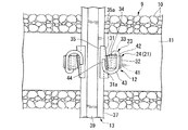
図1は補修作業前におけるTC型省力化軌道の平面図であり、図2は断面図である。なお、以下の説明ではレールの長手方向を前後、幅方向を左右、頭部側を上方とする。
図1,2に示すように、本実施形態の軌道はいわゆるTC型省力化軌道であり、図示しない路盤上に敷き詰められたバラスト10とまくらぎ11とを填充材により一体化させてなる填充層(コンクリート道床)9からなり、まくらぎ11に埋設された座面式締結装置12(以下、第1締結装置12という)と、第1締結装置12に締結されたレール13とを備えている。
まくらぎ11は、コンクリートからなる略直方体形状のものであって、その長手方向が左右方向に一致した状態で填充材に埋設されている。そして、まくらぎ11の上面は填充層9から露出している。なお、まくらぎ11の上面は、左右方向外側から内側に向かって側面視V字状に若干傾斜している。この傾斜は、レール13を鉄道の車輪の傾斜に合わせて傾斜させるものであり、これにより、鉄道は曲線等においてスムーズに曲がることができる。
(Bearing type fastening device)
FIG. 1 is a plan view of a TC-type labor-saving track before repair work, and FIG. 2 is a cross-sectional view. In the following description, the longitudinal direction of the rail is front and rear, the width direction is left and right, and the head side is upward.
As shown in FIGS. 1 and 2, the track of the present embodiment is a so-called TC-type labor-saving track, and is a filling layer formed by integrating a
The
第1締結装置12は、レール13を間に挟んで左右方向で対向するように配置された一対のショルダー(第1ショルダー)21を備えている。ショルダー21は、その下半部に形成されまくらぎ11内に埋設されたアンカー部22と、上半部に形成され後述するクリップ(第1締結手段)23が装着されたショルダー本体24とで構成されている。
アンカー部22は、まくらぎ11の上面から下面に向けて先細るように延出する先細り部27と、この先細り部27の先端が拡大して形成された拡大部28とで構成されている。
The
The
一方、ショルダー本体24は、まくらぎ11の上面から上方に向けて突出形成されている。具体的に、ショルダー本体24は、その左右方向の内側(一対のショルダー本体24の対向面側)に形成されたベース部31と、ベース部31の左右方向外側にベース部31と一体的に形成された支持部32とで構成されている。この場合、ベース部31と支持部32との上面は、緩やかな円弧状に形成されている。
On the other hand, the shoulder
ベース部31には、その前後方向に沿って貫通する円形状の貫通孔33が形成され、この貫通孔33内には筒型インシュレーター34が挿入されている。
また、各ベース部31の対向面は、後述する楔形インシュレーター35に噛合される鋸歯面31aを有している。この鋸歯面31aの長手方向は、前後方向にかけて傾斜しているとともに、各ベース部31の鋸歯面31aの長手方向は互いに平行に形成されている。
The
Moreover, the opposing surface of each
そして、まくらぎ11上における各ショルダー21間には、軌道パッド36を間に挟んでレール13が配置されている。本実施形態のレール13は、左右方向に沿って拡大形成された底部37と、底部37の左右方向中央部から上方に向けて立設された腹部38と、腹部38の上端から幅方向両側方に向かって膨出し、鉄道の車輪(不図示)を支持する頭部39とで構成されている。なお、軌道パッド36は、ゴム等からなる平板状の部材であり、車輪からレール13に伝わる振動等を吸収するためのものである。
A
上述したレール13は、楔形インシュレーター35を介してクリップ23により押圧固定されている。楔形インシュレーター35は、レール13とクリップ23との間の絶縁を図るものであり、レール13の底部37を上面から側面にかけて覆うように形成された側面視L字形状のものである。また、楔形インシュレーター35の側面には、上述したベース部の鋸歯面31aに噛合可能とされた鋸歯面35aが形成されている。このように、ベース部31と楔形インシュレーター35とが噛合することで、楔形インシュレーター35の抜けを防止して、レール13のガタツキを防ぐことができる。
The
クリップ23は、線状のバネ鋼が渦巻状に巻回されたものであり、ショルダー21とレール13との間に介在している。具体的に、クリップ23は、その基端側(内周側)において直線状に形成されショルダー本体24の貫通孔33に挿入される挿入部41と、挿入部41の先端が折り返されて形成されショルダー本体24の支持部32の上面に当接する当接部42と、当接部42の先端から約90度屈曲されるとともに上方に向けて湾曲する湾曲部43と、湾曲部43の先端が約90度屈曲され、楔形インシュレーター35を介してレール13を下方に向けて押圧する押圧部44とで構成されている。すなわち、上述した楔形インシュレーター35は、クリップ23の押圧部44とレール13の底部37の上面との間に介在している。
The
(軌道の補修方法)
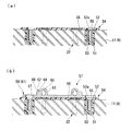
次に、路盤の変状等により填充層9が沈下した場合の軌道の補修方法について説明する。図3,4は図2に相当する軌道の断面図であり、軌道の補修方法を示す工程図である。
図3(a)に示すように、まずまくらぎ11における各ショルダー本体24の両側方に穴51を形成する(穿孔工程)。具体的には、図示しない穿孔機を用いてまくらぎ11を穿孔し、アンカー部22の長さと同程度の深さの穴51をあける。
次に、図3(b)に示すように、穴51内に樹脂材料やセメント等の充填材52を充填するとともに、ボルト穴53aが形成されたインサート部材53を挿入する(インサート設置工程)。そして、この状態で充填材52を養生してボルト穴53aの軸方向がまくらぎ11の上面の面方向に直交するようにインサート部材53を位置決めする。なお、穴51及びインサート部材53は、アンカー部22に接触しない程度にレール13に近接させた方が好ましい。これにより、インサート部材53に後述するボルト71(図5参照)が螺入された際に、レール13からボルト71に作用する曲げモーメントを可能な限り低減することができる。
(Track repair method)
Next, a method for repairing the track when the
As shown in FIG. 3A, first, holes 51 are formed on both sides of each
Next, as shown in FIG. 3B, the
図3(c)に示すように、まくらぎ11の上面からレール13及び第1締結装置12を撤去する(撤去工程)。具体的に、第1締結装置12のクリップ23を取り外した後、レール13、楔形インシュレーター35、軌道パッド36を取り外す。
その後、図示しないカッター等を用いて、ショルダー21におけるまくらぎ11の上面から突出している部分、すなわちショルダー本体24を切断し、その後グラインダ等を用いてショルダー本体24の切断面を研磨する(切断工程)。これにより、まくらぎ11内にアンカー部22が埋設された状態で、ショルダー本体24だけがまくらぎ11上から撤去される。
As shown in FIG.3 (c), the
Thereafter, using a cutter or the like (not shown), the portion of the
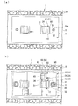
次に、図4(a)に示すように、ショルダー本体24が切断されたまくらぎ11上に絶縁板54を載置する(設置工程)。この絶縁板54は、樹脂材料等の絶縁性を有する材料からなる平板であり、その面方向において上述したインサート部材53のボルト穴53aと重なる位置に貫通孔55を有している。この貫通孔55は、左右方向を長軸方向とする長円形状に形成されている。
なお、上述した切断工程において、ショルダー本体24はまくらぎ11の上面と面一になるように切断することが好ましいが、ショルダー本体24の切断面がまくらぎ11の上面から僅かながら突出して残存する場合がある。そのため、絶縁板54の裏面には、絶縁板54の面方向においてショルダー本体24と重なる位置に、ショルダー本体24の残存部分(まくらぎ11から突出している部分)を収容する凹部(収容部)56が形成されている。これにより、絶縁板54をまくらぎ11上にガタツキなく載置することができ、その後に設置される後述する締結装置57もガタツキなく設置することができる。
Next, as shown to Fig.4 (a), the insulating
In the above-described cutting step, it is preferable to cut the shoulder
ここで、図4(b)に示すように、絶縁板54上に締結装置57をセットする。この締結装置57は、いわゆるタイプレート式締結装置57(以下、第2締結装置57という)であって、タイプレート58と、タイプレート58に装着されレール13を締結するクリップ59(図5参照)とを備えている。タイプレート58は、平板状のプレート61と、プレート61上に形成されたショルダー62とを備えている。
プレート61は、填充層9の沈下量に相当する板厚を有している。また、プレート61は、その面方向において上述したインサート部材53のボルト穴53aと重なるように貫通孔67を有している。この貫通孔67は、上述した絶縁板54の貫通孔55と同様に左右方向を長軸方向とする長円形状に形成されている。このように、絶縁板54及びプレート61の貫通孔55,67を長円形状に形成することで、まくらぎ11上における絶縁板54及びプレート61の左右方向の位置を調整することができる。
Here, as shown in FIG. 4B, the
The
ショルダー62は、プレート61の上面から上方に向けて突出形成されており、レール13の左右両側からレール13を間に挟むように対向配置されている。プレート61は、その左右方向内側(一対のショルダー62の対向面側)に形成されたベース部63と、ベース部63の左右方向外側にベース部63と一体的に形成された支持部64とで構成されている。
ベース部63は、略円柱形状のものであり、その軸方向が前後方向と一致している。そして、ベース部63には、その軸方向に沿って貫通する貫通孔65が形成されている。支持部64は、ベース部63の左右方向外側でベース部63の高さより低く形成され、その上面が平坦面66を有している。
The
The
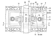
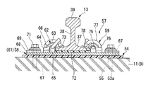
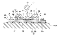
図5は補修作業後における軌道の平面図であり、図6は図5のA−A線に沿う断面図である。
そして、図5,6に示すように、タイプレート58及び絶縁板54の貫通孔55,67内にカバープレート68及び座金69を間に挟んでボルト71を挿通し、インサート部材53(図4参照)のボルト穴53aに螺入する。これにより、タイプレート58がまくらぎ11上に固定される。その後、プレート61上における各ショルダー62間に、ゴム等からなる平板状の軌道パッド72を配置する。
FIG. 5 is a plan view of the track after the repair work, and FIG. 6 is a cross-sectional view taken along the line AA of FIG.
5 and 6, a
次に、プレート61上における各ショルダー62間にレール13を配置した後、レール13の底部37とショルダー62との間にインシュレーター73をセットする(締結工程)。このインシュレーター73は、レール13とクリップ59及びショルダー62との間の絶縁を図るためのものであり、レール13の底部37の上面から側面にかけて覆うように形成された側面視L字形状のものである。また、インシュレーター73の前後方向両側は、ベース部63の前後方向両側面を囲むように形成されている。つまり、インシュレーター73に前後方向に沿う力が作用した場合には、インシュレーター73とショルダー62の側面とが当接して、インシュレーター73の前後方向における移動が規制される。そのため、インシュレーター73の抜けを防止して、レール13のガタツキを防ぐことができる。
Next, after the
最後に、ショルダー62にクリップ59を装着してレール13を締結する。このクリップ59は、上述した第1締結装置12のクリップ23と同様にレール13を押圧固定するためのものであり、線状のバネ鋼が渦巻状に巻回されたものである。具体的に、クリップ59は、その基端側(内周側)に直線状で形成されショルダー62の貫通孔65に挿入される挿入部75と、挿入部75の先端が折り返されて形成され、インシュレーター73を介してレール13を下方に向けて押圧する押圧部78と、押圧部78の先端から上方に向けて湾曲する湾曲部77と、湾曲部77の先端に形成されショルダー62の支持部64における平坦面66に当接する当接部76とで構成されている。
クリップ59をショルダー62に装着する場合、まずクリップ59の挿入部75をショルダー62の貫通孔65に挿入した後、クリップ59の当接部76をショルダー62の支持部64の平坦面66に当接させる。すると、クリップ59に復元力が発生し、この復元力がレール13への押圧力となってクリップ59の押圧部78からインシュレーター73の上面に作用する。これにより、レール13の底部37が下方に向かって押圧されることで、レール13がまくらぎ11上に締結される。
以上により、まくらぎ11上に第2締結装置57によってレール13が締結される。
Finally, the
When the
As described above, the
このように、本実施形態では、軌道の補修時において第1締結装置12のショルダー本体24を撤去した後、座面式締結装置12のまくらぎ11上に第2締結装置57を設置し、この第2締結装置57によりレール13を締結する構成とした。
この構成によれば、まくらぎ11上に第2締結装置57をセットすることで、第1締結装置12に比べてまくらぎ11の上面からレール13の上端面までの高さ(上下方向におけるショルダー62の位置)をプレート61の厚さ分だけ上昇させることができる。すなわち、填充層9の沈下量をプレート61の厚さにより許容することができる。よって、まくらぎ11上に第2締結装置57をセットするだけの簡単な作業で軌道の補修作業を完了させることができる。これにより、TC型省力化軌道のようなまくらぎ11が填充層9内に埋設された直結系軌道であっても、補修作業時に填充層9を掘削する等の必要がないので、作業効率の向上を図るとともに、作業コストの低減を図ることができる。
特に、本実施形態では、軌道の補修作業時において比較的省スペースで補修作業を行うことができるので、軌道の周囲に支障物が配置されている箇所であっても、スムーズな補修作業を実現することができる。
Thus, in this embodiment, after removing the shoulder
According to this configuration, by setting the
In particular, in this embodiment, since the repair work can be performed in a relatively small space during the track repair work, a smooth repair work is realized even in places where obstacles are arranged around the track. can do.
また、撤去工程に先立ってインサート部材53を予め充填材52により固定しておくことで、インサート設置工程とは異なる日に設置工程を行う場合に、第2締結装置57の設置作業を速やかに行うことができる。
さらに、まくらぎ11は、その上面が予め左右方向内側に向けて傾斜して形成されているため、プレート61に傾斜を形成する必要がない。そのため、平板状のタイプレート58をまくらぎ11に設置するのみで、タイプレート58がまくらぎ11の傾斜に倣って傾斜することになる。これにより、タイプレート58の製造コストも低減することが可能である。
Further, by fixing the
Furthermore, since the upper surface of the
また、切断工程において、ショルダー本体24の一部をまくらぎ11から僅かに突出して残存させることで、ショルダー本体24の切断面をまくらぎ11と面一に切断する場合に比べて、ショルダー本体24の切断時に高い切断精度を要求されないため、作業効率の向上を図ることができる。さらに、切断時にまくらぎ11を損傷させる虞もない。
Further, in the cutting step, a part of the
なお、図示しないが填充層9の沈下量がプレート61の厚さよりも大きい場合には、プレート61と絶縁板54との間に鉄やゴム等からなる薄板を介在させてタイプレート58の高さ(まくらぎ11の上面からレール13の上端面までの高さ)を調整することも可能である。
Although not shown, when the sinking amount of the
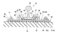
また、填充層9の沈下量が比較的大きい場合には、以下に示すような第2締結装置を用いることも可能である。図7は、第1実施形態における他の構成を示す軌道の断面図である。なお、以下の説明では、上述した第1実施形態と同様の構成については、同一の符号を付し、説明を省略する。
図7に示す第2締結装置81のプレート82は、上述した第1実施形態のプレート61よりも厚さが厚い平板からなり、各ショルダー62間においてレール13が載置される上段部83と、ショルダー62の外側の領域においてプレート82の厚さが縮小するように削り取られた下段部84とで構成されている。すなわち、プレート82は、側面視で階段形状に形成されている。下段部84の厚さは例えば第1実施形態のプレート61の厚さと同等に形成される一方、上段部83の厚さは、下段部84よりも厚く、かつ填充層9の沈下量に相当する厚みに形成されている。また、下段部84には、ボルト71が挿通される貫通孔85が形成されている。
Moreover, when the subsidence amount of the
The plate 82 of the
この構成によれば、上述した第1実施形態と同様の効果を奏することができるとともに、第1実施形態よりも厚さの厚いプレート82を使用することで、填充層9及びまくらぎ11の沈下量が大きい場合であっても、プレート82の上段部83の厚さによって沈下量を許容することができる。特に、プレート82における貫通孔85の形成領域に、上段部83よりも厚さが薄い下段部84を形成することで、プレート82自体の厚さを厚く形成した場合であっても、それに伴いボルト71の長さを長くする必要がない。これにより、上述した第1実施形態の第2締結装置57と同様のボルト71を使用することができるので、コストを低減することができるとともに、ボルト長さの拡大に伴う曲げモーメントの増加を抑制することができる。
According to this configuration, the same effects as those of the above-described first embodiment can be obtained, and the
(第2実施形態)
次に、本発明の第2実施形態について説明する。図8は第2実施形態における軌道の補修方法を示す工程図である。上述した第1実施形態の補修作業では、切断工程において第1締結装置12におけるショルダー本体24を切断する場合について説明したが、本実施形態では、ショルダー本体24を切断せずに補修作業を行う場合について説明する。
なお、本実施形態では、撤去工程までは上述した第1実施形態と同様であるため、説明を省略する。
(Second Embodiment)
Next, a second embodiment of the present invention will be described. FIG. 8 is a process diagram showing a track repair method according to the second embodiment. In the repair work of the first embodiment described above, the case where the
In addition, in this embodiment, since it is the same as that of 1st Embodiment mentioned above until a removal process, description is abbreviate | omitted.
図8(a)に示すように、撤去工程を終えた後、まくらぎ11上に絶縁板91を載置する。この絶縁板91は、上述した第1実施形態と同様に、樹脂材料等の絶縁性を有する材料からなる平板であり、面方向においてショルダー本体24と重なる位置にショルダー本体24を貫通させる矩形孔92が形成されている。
そして、矩形孔92内にショルダー本体24を挿入するように絶縁板91をまくらぎ11上に載置する。これにより、絶縁板91がショルダー本体24を避けた状態でまくらぎ11上に載置される。
As shown in FIG. 8A, after the removal process is completed, the insulating
Then, the insulating
次に、図8(b)に示すように、絶縁板91上に第2締結装置93をセットする。
ここで、本実施形態の第2締結装置93は、タイプレート94と、タイプレート94に装着されレール13を押圧固定するクリップ59(図9参照)とを備えている。タイプレート94は、平板状のプレート95と、プレート95上に形成された一対のショルダー62とを備えている。
Next, as shown in FIG. 8B, the
Here, the
プレート95におけるショルダー本体24と面方向で重なる位置には、ショルダー本体24を貫通させる矩形孔(逃げ部)96が形成されている。ショルダー62は、レール13の左右両側からレール13を間に挟むように設けられるとともに、プレート95上における前後方向で異なる位置に配置されている。すなわち、一方のショルダー62はプレート95上における矩形孔96よりも前側に配置され、他方のショルダー62はプレート95上における矩形孔96よりも後方に配置されている。
そして、矩形孔96内にショルダー本体24を挿入するようにタイプレート94をまくらぎ11上に載置する。これにより、タイプレート94がショルダー本体24を避けた状態でまくらぎ11上に載置される。
A rectangular hole (escape portion) 96 through which the
Then, the
次に、図9,10に示すように、上述した第1実施形態と同様に、タイプレート94をボルト71によりまくらぎ11に固定するとともに、クリップ59を用いてレール13を第2締結装置93に締結する。
Next, as shown in FIGS. 9 and 10, as in the first embodiment described above, the
このように、本実施形態によれば、上述した第1実施形態と同様の効果を奏することができる。
さらに、本実施形態では、上述した第1実施形態と異なりショルダー本体24を切断する必要がないので、作業効率の更なる向上を図ることができる。
Thus, according to this embodiment, the same effects as those of the first embodiment described above can be achieved.
Furthermore, in the present embodiment, unlike the first embodiment described above, it is not necessary to cut the shoulder
なお、本実施形態においても、填充層9の沈下量が比較的大きい場合には、上述した第1実施形態と同様に、図11に示すように上段部97及び下段部98を有する側面視階段形状のタイプレート99を用いることが可能である。
Also in this embodiment, when the subsidence amount of the
なお、本発明の技術範囲は上述した実施形態に限られるものではなく、本発明の趣旨を逸脱しない範囲において、上述した実施形態に種々の変更を加えたものを含む。すなわち、実施形態で挙げた具体的な構造や形状などはほんの一例に過ぎず、適宜変更が可能である。
例えば、上述した実施形態では、路盤上にまくらぎ11及びバラスト10が填充層9として一体化されてなるTC型省力化軌道の補修方法を例にして説明したが、これに限らずコンクリート路盤にまくらぎが埋設された直結系軌道や、コンクリート路盤上に軌道スラブ(コンクリート道床)が設置されたスラブ軌道、コンクリート路盤上にゴム等の弾性部材を介してまくらぎが設置された弾性まくらぎ直結軌道等、何れの直結系軌道においても上述した軌道の補修方法を採用することが可能である。
The technical scope of the present invention is not limited to the above-described embodiment, and includes various modifications made to the above-described embodiment without departing from the spirit of the present invention. That is, the specific structure and shape described in the embodiment are merely examples, and can be changed as appropriate.
For example, in the above-described embodiment, the TC-type labor-saving track repair method in which the
また、上述した実施形態では、穴51内に充填された充填材52にインサート部材53を埋設する構成について説明したが、穴51内に打ち込み式の雌ねじアンカー(いわゆるホークアンカー)を直接設ける構成にしても構わない。
さらに、第1実施形態において、絶縁板54の裏面に各ショルダー本体24の切断面を収容する凹部56をそれぞれ形成する場合について説明したが、これに限らず左右方向に長い凹部を形成して各ショルダー本体24の切断面を一括して収容するようにしても構わない。
また、第2実施形態において、ショルダー62をプレート95上における前後方向で異なる位置に配置する構成について説明したが、これに限られず、矩形孔92の前後何れか一方で互いに対向するようにショルダー62を配置しても構わない。
In the above-described embodiment, the structure in which the
Furthermore, in the first embodiment, the case where the
In the second embodiment, the configuration in which the
9…填充層(コンクリート道床) 11…まくらぎ 12…第1締結装置 13…レール 21…ショルダー(第1ショルダー) 23…クリップ(第1締結手段) 54…絶縁板 56…凹部(収容部) 57,81,93…第2締結装置 59…第2締結手段 61,82,95…プレート(ベース部) 62…ショルダー(第2ショルダー) 71…ボルト(締結部材) 83,97…上段部 84,98…下段部 96…矩形孔(逃げ部)
DESCRIPTION OF
Claims (4)
前記コンクリート道床に設置され、前記レールの幅方向両側において一部が前記コンクリート道床に埋設された一対の第1ショルダー、及び第1ショルダーに装着され、前記レールの底部を前記コンクリート道床に向けて押圧する第1締結手段を有する第1締結装置と、を備えた直結系軌道の補修方法であって、
前記第1ショルダーから前記レール及び前記第1締結手段を取り外す撤去工程と、
前記第1ショルダーにおける前記コンクリート道床からの突出部分を切断する切断工程と、
前記コンクリート道床上に第2締結装置を設置する設置工程と、
前記第2締結装置によって前記レールを締結する締結工程とを有し、
前記第2締結装置として、前記コンクリート道床と前記レールとの間に配置され、高さ調整に応じた厚さを有するベース部と、前記ベース部上における前記レールの幅方向両側に形成された一対の第2ショルダーと、前記第2ショルダーに装着され、前記レールの底部を前記ベース部に向けて押圧する第2締結手段とを備えるものを使用し、
前記設置工程では、前記コンクリート道床上に前記ベース部及び前記一対の第2ショルダーを設置し、
前記締結工程では、前記ベース部に前記レールを設置した後に、前記第2ショルダーに前記第2締結手段を装着することで前記レールの底部を前記ベース部に向けて押圧させることを特徴とする直結系軌道の補修方法。 A concrete roadbed that supports the rails,
A pair of first shoulders installed on the concrete roadbed and partially embedded in the concrete roadbed on both sides in the width direction of the rails, and attached to the first shoulder, and pressing the bottom of the rails toward the concrete roadbed A first coupling device having a first fastening means, and a repair method for a direct connection system track, comprising:
Removing the rail and the first fastening means from the first shoulder;
A cutting step of cutting a protruding portion from the concrete roadbed in the first shoulder;
An installation step of installing a second fastening device on the concrete roadbed;
A fastening step of fastening the rail by the second fastening device;
As the second fastening device, a pair of base portions disposed between the concrete roadbed and the rails and having a thickness corresponding to height adjustment, and a pair formed on both sides of the rail in the width direction on the base portion. And a second fastening means that is attached to the second shoulder and that presses the bottom of the rail toward the base,
In the installation step, the base portion and the pair of second shoulders are installed on the concrete roadbed,
In the fastening step, after the rail is installed on the base portion, the bottom portion of the rail is pressed toward the base portion by attaching the second fastening means to the second shoulder. System orbit repair method.
前記絶縁板における前記コンクリート道床との対向面には、前記切断工程において残存する前記第1ショルダーの一部を収容する収容部が形成されていることを特徴とする請求項1記載の直結系軌道の補修方法。 In the installation step, an insulating plate is disposed between the base portion and the concrete roadbed,
The direct connection type track according to claim 1, wherein an accommodation portion for accommodating a part of the first shoulder remaining in the cutting step is formed on a surface of the insulating plate facing the concrete roadbed. Repair method.
前記コンクリート道床上に設置され、前記レールの幅方向両側において一部が前記コンクリート道床に埋設された一対の第1ショルダー、及び第1ショルダーに装着され、前記レールの底部を前記コンクリート道床に向けて押圧する第1締結手段とを有する第1締結装置と、を備えた直結系軌道の補修方法であって、
前記第1ショルダーから前記レール及び前記第1締結手段を取り外す撤去工程と、
前記コンクリート道床上に第2締結装置を設置する設置工程と、
前記第2締結装置によって前記レールを締結する締結工程とを有し、
前記第2締結装置として、前記コンクリート道床と前記レールとの間に配置され、高さ調整に応じた厚さを有するベース部と、前記ベース部上における前記レールの幅方向両側に形成された一対の第2ショルダーと、前記第2ショルダーに装着され、前記レールの底部を前記ベース部に向けて押圧する第2締結手段とを備え、前記ベース部に、前記第1ショルダーにおける前記コンクリート道床からの突出部分を避ける逃げ部が形成されたものを使用し、
前記設置工程では、前記第1ショルダーにおける前記コンクリート道床からの突出部分と前記逃げ部とを重ね合わせた状態で、前記コンクリート道床上に前記ベース部及び前記一対の第2ショルダーを設置し、
前記締結工程では、前記ベース部に前記レールを設置した後に、前記第2ショルダーに前記第2締結手段を装着することで前記レールの底部を前記ベース部に向けて押圧させることを特徴とする直結系軌道の補修方法。 A concrete roadbed that supports the rails,
A pair of first shoulders installed on the concrete roadbed and partially embedded in the concrete roadbed on both sides in the width direction of the rail, and attached to the first shoulder, with the bottom of the rail facing the concrete roadbed A first coupling device having a first fastening means for pressing, and a repair method for a direct connection system track, comprising:
Removing the rail and the first fastening means from the first shoulder;
An installation step of installing a second fastening device on the concrete roadbed;
A fastening step of fastening the rail by the second fastening device;
As the second fastening device, a pair of base portions disposed between the concrete roadbed and the rails and having a thickness corresponding to height adjustment, and a pair formed on both sides of the rail in the width direction on the base portion. And a second fastening means that is attached to the second shoulder and presses the bottom of the rail toward the base portion, and the base portion has the second shoulder from the concrete roadbed in the first shoulder. Use the one where the escape part that avoids the protruding part is formed,
In the installation step, the base portion and the pair of second shoulders are installed on the concrete roadbed in a state where the protruding portion from the concrete roadbed and the escape portion in the first shoulder are overlapped,
In the fastening step, after the rail is installed on the base portion, the bottom portion of the rail is pressed toward the base portion by attaching the second fastening means to the second shoulder. System orbit repair method.
前記設置工程では、締結部材を用いて前記下段部を前記コンクリート道床に固定することを特徴とする請求項1ないし請求項3の何れか1項に記載の直結系軌道の補修方法。 The base part of the second fastening device includes an upper stage part on which the rail is placed, and a lower stage part formed on both sides in the width direction of the upper stage part and having a height reduced from the upper stage part,
The method for repairing a direct connection track according to any one of claims 1 to 3, wherein, in the installation step, the lower step portion is fixed to the concrete roadbed using a fastening member.
Priority Applications (1)
| Application Number | Priority Date | Filing Date | Title |
|---|---|---|---|
| JP2009257107A JP5410926B2 (en) | 2009-11-10 | 2009-11-10 | Repair method for direct track |
Applications Claiming Priority (1)
| Application Number | Priority Date | Filing Date | Title |
|---|---|---|---|
| JP2009257107A JP5410926B2 (en) | 2009-11-10 | 2009-11-10 | Repair method for direct track |
Publications (2)
| Publication Number | Publication Date |
|---|---|
| JP2011102473A true JP2011102473A (en) | 2011-05-26 |
| JP5410926B2 JP5410926B2 (en) | 2014-02-05 |
Family
ID=44192913
Family Applications (1)
| Application Number | Title | Priority Date | Filing Date |
|---|---|---|---|
| JP2009257107A Expired - Fee Related JP5410926B2 (en) | 2009-11-10 | 2009-11-10 | Repair method for direct track |
Country Status (1)
| Country | Link |
|---|---|
| JP (1) | JP5410926B2 (en) |
Cited By (7)
| Publication number | Priority date | Publication date | Assignee | Title |
|---|---|---|---|---|
| JP2014095229A (en) * | 2012-11-09 | 2014-05-22 | Nippon Senro Gijutsu:Kk | Height adjustment method for rail |
| JP2016108808A (en) * | 2014-12-05 | 2016-06-20 | 東日本旅客鉄道株式会社 | Tie shoulder cutter |
| CN106320114A (en) * | 2016-09-07 | 2017-01-11 | 中国铁路总公司 | Method for repairing damage to high-speed-railway base plate concrete |
| CN111501441A (en) * | 2020-05-11 | 2020-08-07 | 武汉坤能轨道系统技术有限公司 | Settlement adjustment method and system suitable for ballastless track with shoulder |
| JP2020122345A (en) * | 2019-01-31 | 2020-08-13 | 三洲産業株式会社 | Rail fixing device |
| JP2021004514A (en) * | 2019-06-27 | 2021-01-14 | 東日本旅客鉄道株式会社 | Rail fastening device for slab track |
| KR102743135B1 (en) * | 2024-07-10 | 2024-12-16 | 주식회사 세안 | Railway turnout rail fastening apparatus |
Citations (7)
| Publication number | Priority date | Publication date | Assignee | Title |
|---|---|---|---|---|
| JPH0676401U (en) * | 1993-04-13 | 1994-10-28 | 鉄道軌材工業株式会社 | Rail fastening device with adjustable track gauge |
| JPH11222801A (en) * | 1998-02-05 | 1999-08-17 | Nihon Decoluxe Co Ltd | Repair method for embedded plug of concrete sleeper |
| JP2001020202A (en) * | 1999-07-06 | 2001-01-23 | Teito Rapid Transit Authority | Sleeper elastic track device |
| JP2005163425A (en) * | 2003-12-04 | 2005-06-23 | Odakyu Dentetsu Kk | Wire spring retainer for rail fastening device |
| JP2008013977A (en) * | 2006-07-04 | 2008-01-24 | Tetsudo Kizai Kogyo Kk | Rail fastening device with screw-type shoulder |
| JP2009018895A (en) * | 2007-07-11 | 2009-01-29 | Murata Mach Ltd | Rail fixing device and method |
| JP2009114787A (en) * | 2007-11-08 | 2009-05-28 | Keihin Electric Express Railway Co Ltd | Joint device for changing rail specification |
-
2009
- 2009-11-10 JP JP2009257107A patent/JP5410926B2/en not_active Expired - Fee Related
Patent Citations (7)
| Publication number | Priority date | Publication date | Assignee | Title |
|---|---|---|---|---|
| JPH0676401U (en) * | 1993-04-13 | 1994-10-28 | 鉄道軌材工業株式会社 | Rail fastening device with adjustable track gauge |
| JPH11222801A (en) * | 1998-02-05 | 1999-08-17 | Nihon Decoluxe Co Ltd | Repair method for embedded plug of concrete sleeper |
| JP2001020202A (en) * | 1999-07-06 | 2001-01-23 | Teito Rapid Transit Authority | Sleeper elastic track device |
| JP2005163425A (en) * | 2003-12-04 | 2005-06-23 | Odakyu Dentetsu Kk | Wire spring retainer for rail fastening device |
| JP2008013977A (en) * | 2006-07-04 | 2008-01-24 | Tetsudo Kizai Kogyo Kk | Rail fastening device with screw-type shoulder |
| JP2009018895A (en) * | 2007-07-11 | 2009-01-29 | Murata Mach Ltd | Rail fixing device and method |
| JP2009114787A (en) * | 2007-11-08 | 2009-05-28 | Keihin Electric Express Railway Co Ltd | Joint device for changing rail specification |
Cited By (9)
| Publication number | Priority date | Publication date | Assignee | Title |
|---|---|---|---|---|
| JP2014095229A (en) * | 2012-11-09 | 2014-05-22 | Nippon Senro Gijutsu:Kk | Height adjustment method for rail |
| JP2016108808A (en) * | 2014-12-05 | 2016-06-20 | 東日本旅客鉄道株式会社 | Tie shoulder cutter |
| CN106320114A (en) * | 2016-09-07 | 2017-01-11 | 中国铁路总公司 | Method for repairing damage to high-speed-railway base plate concrete |
| JP2020122345A (en) * | 2019-01-31 | 2020-08-13 | 三洲産業株式会社 | Rail fixing device |
| JP7029178B2 (en) | 2019-01-31 | 2022-03-03 | 三洲産業株式会社 | Rail fixing device |
| JP2021004514A (en) * | 2019-06-27 | 2021-01-14 | 東日本旅客鉄道株式会社 | Rail fastening device for slab track |
| JP7260418B2 (en) | 2019-06-27 | 2023-04-18 | 東日本旅客鉄道株式会社 | Rail fastener for slab track |
| CN111501441A (en) * | 2020-05-11 | 2020-08-07 | 武汉坤能轨道系统技术有限公司 | Settlement adjustment method and system suitable for ballastless track with shoulder |
| KR102743135B1 (en) * | 2024-07-10 | 2024-12-16 | 주식회사 세안 | Railway turnout rail fastening apparatus |
Also Published As
| Publication number | Publication date |
|---|---|
| JP5410926B2 (en) | 2014-02-05 |
Similar Documents
| Publication | Publication Date | Title |
|---|---|---|
| JP5410926B2 (en) | Repair method for direct track | |
| JP4887381B2 (en) | Railway rail fixing clip | |
| KR101670308B1 (en) | Resilient rail support block assembly | |
| CN203429513U (en) | Cavity filling part, and track fixing device in pedestal | |
| CN102301070B (en) | Railway clip insulator with two stable positions for standby, parked or preloaded position and installed, loaded or final position | |
| JP5824424B2 (en) | Track slab restraint structure, restraint jig, and method for forming race slab restraint structure | |
| JP5156219B2 (en) | Rail fastening device for high and low displacement adjustment | |
| JP6204169B2 (en) | Rail fastening device for track | |
| JP5276801B2 (en) | Labor-saving track reinforcement method | |
| CN111501428A (en) | Direct-buried fastener and construction method thereof | |
| JP4465459B2 (en) | PC plate for lining and mounting structure of PC plate for lining | |
| JP3058592B2 (en) | Rail fastening device with height adjustment function | |
| JP2008057314A (en) | Road surface repair method, rolling plate and guide member used therefor | |
| KR20150026271A (en) | Device For Restoring Railroad Sink Automatically | |
| JP2010163755A (en) | Wheel runaway preventing apparatus | |
| JP6670631B2 (en) | Support structure for columnar structures | |
| CN212316560U (en) | Direct-buried fastener | |
| JP2003064602A (en) | Elastic sleepers | |
| KR200467323Y1 (en) | A rail structure and a rail assembly for the same | |
| JP4020918B2 (en) | Bridge structure of girder bridge | |
| KR102587474B1 (en) | Apparatus for fixing parts of tram track | |
| JP2003082601A (en) | Ballast-resistance increase of concrete sleeper | |
| JP2003041503A (en) | Tool for increasing resistance of tie to ballast | |
| KR20140000516U (en) | Rail fastening apparatus for controlling the uplift force in bridge | |
| KR102321730B1 (en) | Lifting apparatus for concrete-track and lifting method using the same |
Legal Events
| Date | Code | Title | Description |
|---|---|---|---|
| A621 | Written request for application examination |
Free format text: JAPANESE INTERMEDIATE CODE: A621 Effective date: 20120928 |
|
| A977 | Report on retrieval |
Free format text: JAPANESE INTERMEDIATE CODE: A971007 Effective date: 20130726 |
|
| A131 | Notification of reasons for refusal |
Free format text: JAPANESE INTERMEDIATE CODE: A131 Effective date: 20130806 |
|
| A521 | Request for written amendment filed |
Free format text: JAPANESE INTERMEDIATE CODE: A523 Effective date: 20130906 |
|
| A977 | Report on retrieval |
Free format text: JAPANESE INTERMEDIATE CODE: A971007 Effective date: 20130920 |
|
| TRDD | Decision of grant or rejection written | ||
| A01 | Written decision to grant a patent or to grant a registration (utility model) |
Free format text: JAPANESE INTERMEDIATE CODE: A01 Effective date: 20131022 |
|
| A61 | First payment of annual fees (during grant procedure) |
Free format text: JAPANESE INTERMEDIATE CODE: A61 Effective date: 20131107 |
|
| R150 | Certificate of patent or registration of utility model |
Ref document number: 5410926 Country of ref document: JP Free format text: JAPANESE INTERMEDIATE CODE: R150 |
|
| R250 | Receipt of annual fees |
Free format text: JAPANESE INTERMEDIATE CODE: R250 |
|
| R250 | Receipt of annual fees |
Free format text: JAPANESE INTERMEDIATE CODE: R250 |
|
| R250 | Receipt of annual fees |
Free format text: JAPANESE INTERMEDIATE CODE: R250 |
|
| R250 | Receipt of annual fees |
Free format text: JAPANESE INTERMEDIATE CODE: R250 |
|
| R250 | Receipt of annual fees |
Free format text: JAPANESE INTERMEDIATE CODE: R250 |
|
| R250 | Receipt of annual fees |
Free format text: JAPANESE INTERMEDIATE CODE: R250 |
|
| LAPS | Cancellation because of no payment of annual fees |