JP2011102073A - Pneumatic tire - Google Patents
Pneumatic tire Download PDFInfo
- Publication number
- JP2011102073A JP2011102073A JP2009257353A JP2009257353A JP2011102073A JP 2011102073 A JP2011102073 A JP 2011102073A JP 2009257353 A JP2009257353 A JP 2009257353A JP 2009257353 A JP2009257353 A JP 2009257353A JP 2011102073 A JP2011102073 A JP 2011102073A
- Authority
- JP
- Japan
- Prior art keywords
- tire
- groove
- tread
- shoulder
- circumferential direction
- Prior art date
- Legal status (The legal status is an assumption and is not a legal conclusion. Google has not performed a legal analysis and makes no representation as to the accuracy of the status listed.)
- Granted
Links
Images


Abstract
Description
本発明は、氷上性能と轍走行性能とをバランス良く向上させた空気入りタイヤに関する。 The present invention relates to a pneumatic tire that improves on-ice performance and saddle running performance in a well-balanced manner.
従来より、トレッド幅やランド比を大きくし、接地面積を大きく確保した空気入りタイヤが提案されている。このような空気入りタイヤは、路面に対して大きな摩擦力が得られるため、氷路面において走行性能が向上する。 Conventionally, a pneumatic tire has been proposed in which a tread width and a land ratio are increased to ensure a large contact area. Since such a pneumatic tire can obtain a large frictional force with respect to the road surface, traveling performance is improved on an icy road surface.
ところで、上述の空気入りタイヤでは、図10(a)に示されるように、規格で定められた正規荷重n1が負荷された場合には、適正な接地幅w1が確保されるため最適でかつ大きな接地面積が得られるが、正規荷重に満たない比較的小さな荷重n2の場合は、図10(b)に示されるように、前記接地幅w1よりも小さい接地幅w2となるため、所望の接地面積を得ることが出来ない。 By the way, in the above-mentioned pneumatic tire, as shown in FIG. 10 (a), when a normal load n1 determined by the standard is applied, an appropriate grounding width w1 is ensured, so that it is optimal and large. Although a ground contact area can be obtained, in the case of a relatively small load n2 less than the normal load, as shown in FIG. 10B, the ground contact width w2 is smaller than the ground contact width w1, so that a desired ground contact area is obtained. Can not get.
また、トレッド幅を大きくした空気入りタイヤは、トレッド端やバットレス面の一部が轍の斜面等に接触し易く、ひいては路面からの外力によってタイヤがふらつくワンダリングが生じやすい。このため、接地面積を大きくすることは、氷上性能を高める一方で、耐ワンダリング性能を悪化させるという問題がある。関連する技術としては次のものがある。 Also, a pneumatic tire having a wide tread width is likely to cause wandering in which a part of the tread or a buttress surface easily comes into contact with a slope of a kite or the like, and the tire fluctuates due to an external force from the road surface. For this reason, increasing the ground contact area increases the performance on ice while deteriorating the wandering resistance. Related technologies include the following.
本発明は、以上のような問題点に鑑み案出なされたもので、タイヤ最大幅に対するトレッド幅を大きくするとともに、バットレス面に、タイヤ周方向に連続してのびる特定形状の細溝を設けることを基本として、荷重状態に拘わらず最適な接地面積を確保して氷上性能を高めるとともに、耐ワンダリング性能をも向上させた空気入りタイヤを提供することを主たる目的としている。 The present invention has been devised in view of the above-described problems. The tread width with respect to the maximum tire width is increased, and a specific-shaped narrow groove extending continuously in the tire circumferential direction is provided on the buttress surface. The main objective is to provide a pneumatic tire that secures an optimum ground contact area regardless of the load state, improves the performance on ice, and also improves the anti-wandering performance.
本発明のうち請求項1記載の発明は、トレッド部からサイドウォール部を経てビード部のビードコアに至るカーカスと、このカーカスのタイヤ半径方向外側かつ前記トレッド部の内部に配されたベルト層とを具えた空気入りタイヤであって、正規リムに装着されかつ正規内圧が充填された無負荷である正規状態において、トレッド端間のトレッド幅TWとタイヤ最大幅SWとの比TW/SWが0.75〜0.95であり、前記サイドウォール部のタイヤ半径方向の外方領域であるバットレス面には、タイヤ周方向に連続してのびる細溝が設けられるとともに、前記正規状態におけるタイヤ回転軸を含むタイヤ子午線断面において、前記細溝の中心線と、該中心線の延長線と前記カーカスとが交差する交点を通るカーカスの法線とのなす角度が10度以内であり、しかも前記トレッド部には、最もトレッド端側をタイヤ周方向に連続してのびる一対のショルダー主溝が設けられるともに、前記細溝の溝深さが、前記ショルダー主溝の溝深さの20〜50%であることを特徴とする。 The invention according to claim 1 of the present invention includes a carcass extending from the tread portion to the bead core of the bead portion through the sidewall portion, and a belt layer disposed outside the carcass in the tire radial direction and inside the tread portion. In a normal state in which the pneumatic tire is equipped with a normal rim and is not loaded with a normal internal pressure, the ratio TW / SW between the tread width TW between the tread ends and the tire maximum width SW is 0. The buttress surface which is 75 to 0.95 and is an outer region in the tire radial direction of the sidewall portion is provided with a narrow groove extending continuously in the tire circumferential direction, and the tire rotation shaft in the normal state is In the tire meridian cross section, the angle formed by the center line of the narrow groove and the normal line of the carcass passing through the intersection where the extension line of the center line intersects the carcass is The tread portion is provided with a pair of shoulder main grooves extending continuously in the tire circumferential direction at the tread end side, and the groove depth of the narrow groove is equal to that of the shoulder main groove. It is characterized by being 20 to 50% of the groove depth.
また請求項2記載の発明は、前記細溝は、ビードベースラインからタイヤ断面高さの80%以上かつ90%以下の領域に設けられる請求項1記載の空気入りタイヤである。
The invention according to
また請求項3記載の発明は、前記細溝の溝底と、前記交点との最短距離は、3〜8mmである請求項1又は2に記載の空気入りタイヤである。
The invention according to claim 3 is the pneumatic tire according to
また請求項4記載の発明は、前記トレッド部は、前記ショルダー主溝とトレッド端との間をのびるショルダー横溝が、タイヤ周方向に隔設されることにより複数のショルダーブロックがタイヤ周方向に並ぶショルダーブロック列が設けられるとともに、前記ショルダーブロック列は、前記ショルダーブロックのタイヤ軸方向外側の外壁面と、該ショルダーブロックの踏面とが交差する交差部がその全長さに亘って面取りされた切欠きブロックが、タイヤ周方向に一つおきに設けられる請求項1乃至3のいずれかに記載の空気入りタイヤである。 According to a fourth aspect of the present invention, in the tread portion, a shoulder lateral groove extending between the shoulder main groove and the tread end is spaced apart in the tire circumferential direction, so that a plurality of shoulder blocks are arranged in the tire circumferential direction. A shoulder block row is provided, and the shoulder block row is a notch in which a crossing portion where the outer wall surface of the shoulder block in the tire axial direction and the tread surface of the shoulder block intersect is chamfered over its entire length. The pneumatic tire according to claim 1, wherein every other block is provided in the tire circumferential direction.
また請求項5記載の発明は、前記トレッド部は、前記ショルダー主溝とトレッド端との間をのびるショルダー横溝が、タイヤ周方向に隔設されることにより複数のショルダーブロックがタイヤ周方向に並ぶショルダーブロック列が設けられるとともに、前記ショルダーブロック列は、前記外壁面と、前記踏面と、前記ショルダー横溝に面するブロック壁面とが交差する頂部を三角形状の斜面で面取りされた切欠きブロックが、タイヤ周方向に連続して設けられる請求項1乃至3のいずれかに記載の空気入りタイヤである。 According to a fifth aspect of the present invention, in the tread portion, a shoulder lateral groove extending between the shoulder main groove and the tread end is provided in the tire circumferential direction, whereby a plurality of shoulder blocks are arranged in the tire circumferential direction. A shoulder block row is provided, and the shoulder block row is a notched block chamfered with a triangular slope at the top where the outer wall surface, the tread surface, and the block wall surface facing the shoulder lateral groove intersect. The pneumatic tire according to any one of claims 1 to 3, wherein the pneumatic tire is provided continuously in a tire circumferential direction.
本発明の空気入りタイヤは、正規状態において、トレッド幅がタイヤ最大幅の0.75〜0.95倍と幅広に形成される。また、バットレス面には、タイヤ周方向に連続してのびる細溝が設けられるとともに、この細溝を特定の形状に限定する。具体的には、正規状態におけるタイヤ回転軸を含むタイヤ子午線断面において、細溝は、その中心線と、該中心線の延長線と前記カーカスとが交差する交点を通るカーカスの法線とのなす角度が10度以内をなす。また、細溝の深さは、ショルダー主溝の溝深さの20〜50%に定められる。 In the normal state, the pneumatic tire of the present invention is formed to have a wide tread width of 0.75 to 0.95 times the tire maximum width. The buttress surface is provided with a narrow groove extending continuously in the tire circumferential direction, and the narrow groove is limited to a specific shape. Specifically, in the tire meridian cross section including the tire rotation axis in the normal state, the narrow groove is formed by a center line thereof and a normal line of the carcass passing through an intersection where the extension line of the center line intersects the carcass. The angle is within 10 degrees. The depth of the narrow groove is set to 20 to 50% of the depth of the shoulder main groove.
種々の実験の結果、上述のように規定された細溝は、バットレス部の剛性の低下を図り、正規荷重よりも小さい荷重が負荷された状態においても、バットレス部を柔軟に変形させ、接地面積を大きく確保することができる。また、轍の斜面にトレッド端ないしバットレス面が接触した場合でも、前記細溝を起点としてバットレス面の細溝を変形させて路面からの反力を吸収し、ワンダリングの発生を防止できる。このように、本発明の空気入りタイヤは、接地面積を大きく確保して氷上性能の向上を図りつつ耐ワンダリング性能を向上できる。 As a result of various experiments, the narrow groove defined as described above reduces the rigidity of the buttress part and flexibly deforms the buttress part even when a load smaller than the normal load is applied. Can be secured greatly. Even when the tread edge or buttress surface comes into contact with the slope of the ridge, the narrow groove of the buttress surface is deformed from the narrow groove as a starting point to absorb the reaction force from the road surface, thereby preventing the occurrence of wandering. As described above, the pneumatic tire of the present invention can improve the wandering resistance performance while ensuring a large contact area and improving the performance on ice.
また、請求項4又は5記載の空気入りタイヤでは、ショルダーブロックの外側面を切り欠くことにより、轍に衝突したときでも路面からの反力をさらに小さくできる。このため、より一層、耐ワンダリング性能が向上する。
Further, in the pneumatic tire according to
以下、本発明の実施の一形態を図面に基づき説明される。
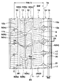
図1は本実施形態の空気入りタイヤ1の右半分断面図、図2はその展開図がそれぞれ示される。なお、図1の断面図は、正規リム(図示せず)にリム組みされかつ正規内圧が充填された無負荷の正規状態におけるタイヤ回転軸を含む子午線断面を表す。特に断りがない場合、タイヤ各部の寸法等は、この正規状態で測定された値である。
Hereinafter, an embodiment of the present invention will be described with reference to the drawings.
FIG. 1 is a right half sectional view of the pneumatic tire 1 of the present embodiment, and FIG. 2 is a development view thereof. The cross-sectional view of FIG. 1 represents a meridian cross section including a tire rotation axis in a normal state in which the rim is assembled on a normal rim (not shown) and is filled with a normal internal pressure. When there is no notice in particular, the dimension of each part of a tire, etc. are values measured in this normal state.
前記「正規リム」とは、タイヤが基づいている規格を含む規格体系において、各規格がタイヤ毎に定めているリムであり、JATMAであれば"標準リム"、TRAであれば "Design Rim" 、ETRTOであれば "Measuring Rim"となる。また、前記「正規内圧」とは、タイヤが基づいている規格を含む規格体系において、各規格がタイヤ毎に定めている空気圧であり、JATMAであれば"最高空気圧"、TRAであれば表 "TIRE LOAD LIMITS AT VARIOUS COLD INFLATION PRESSURES" に記載の最大値、ETRTOであれば "INFLATION PRESSURE" とする。 The “regular rim” is a rim defined for each tire in the standard system including the standard on which the tire is based. “Standard Rim” for JATMA, “Design Rim” for TRA For ETRTO, "Measuring Rim". In addition, the “regular internal pressure” is an air pressure determined by each standard for each tire in the standard system including the standard on which the tire is based. TIRE LOAD LIMITS AT VARIOUS COLD INFLATION PRESSURES "Maximum value", ETRTO, "INFLATION PRESSURE".
本実施形態の空気入りタイヤ(以下、単に「タイヤ」ということがある。)1は、図1に示されるように、トレッド部2からサイドウォール部3をへてビード部4のビードコア5に至るカーカス6と、このカーカス6の半径方向外側かつトレッド部2の内部に配されるベルト層7とを具え、本実施形態では、乗用車用のスタッドレスタイヤが示されている。
As shown in FIG. 1, the pneumatic tire (hereinafter, simply referred to as “tire”) 1 of the present embodiment reaches the
前記カーカス6は、一対のビードコア5、5間をトロイド状に跨る本体部6aと、この本体部6aの両側に連なりかつ前記ビードコア5の回りでタイヤ軸方向内側から外側に折り返された折返し部6bとを有する少なくとも1枚のカーカスプライ6Aからなる。前記カーカスプライ6Aは、例えば有機繊維からなるカーカスコードがタイヤ赤道C方向に対して例えば75〜90°の角度で配列されている。
The
前記ベルト層7は、例えば、タイヤ半径方向内、外2枚のベルトプライ7A、7Bからなり、内のベルトプライ7Aが、外のベルトプライ7Bに比べて幅広に形成される。各ベルトプライ7A、7Bは、タイヤ赤道Cに対して15〜40°の角度で傾けられた例えばスチールコード等の高弾性のベルトコードを有する。そして、各ベルトプライ7A、7Bは、ベルトコードが互いに交差するように傾けられている。これによって、ベルト層7は、トレッド部2の略全幅に亘ってカーカス6をタガ締めし、トレッド部2の剛性を高めている。
The
前記トレッド部2には、タイヤ周方向に連続してのびる複数本の主溝8と、該主溝8と交わる向きにのびる複数本の横溝9とが設けられている。これらの主溝8及び横溝9は、排水及び雪柱せん断機能を発揮しうる。
The
前記主溝8は、例えばタイヤ赤道Cの最も近くに配されかつその両側をタイヤ周方向にのびる一対のセンター主溝8aと、その外側に配された一対のミドル主溝8bと、さらにそのタイヤ軸方向外側に配されかつ最もトレッド端Te側をのびる一対のショルダー主溝8cとを含む。本実施形態の主溝8は、いずれも直線状で形成されるため、優れた排水性能を発揮しかつ制動時の車両のふらつきや片流れなどの不安定な挙動を抑制することが可能となり、操縦安定性能を確保できる点で望ましい。なお、主溝8の形状は、図示の形態に制限されることなく適宜変更できる。
The
また、前記トレッド部2には、センター主溝8a、8a間をのびる1本のセンター陸部10と、前記センター主溝8aとミドル主溝8bとの間をのびる一対の第1のミドル陸部11と、前記ミドル主溝8bと前記ショルダー主溝8cとの間をのびる一対の第2のミドル陸部12と、前記ショルダー主溝8cのタイヤ軸方向外側をのびる一対のショルダー陸部13とがそれぞれ形成される。
The
また、前記センター陸部10、前記一対の第1のミドル陸部11、前記一対の第2のミドル陸部12及び前記一対のショルダー陸部13には、それぞれセンター横溝9a、第1のミドル横溝9b、第2のミドル横溝9c及びショルダー横溝9dが形成される。これにより、各陸部10ないし13は、それぞれセンターブロック10b、第1のミドルブロック11b、第2のミドルブロック12b及びショルダーブロック13bがタイヤ周方向に並ぶセンターブロック列10R、第1のミドルブロック列11R、第2のミドルブロック列12R及びショルダーブロック列13Rとして構成される。なお、各ブロック10bないし13bには、例えばタイヤ軸方向にジグザグ状にのびる複数本のサイピングsが形成されるのが望ましい。
The
図1及び2に示されるように、センター主溝8a及びミドル主溝8bの溝幅(溝の長手方向と直角な溝幅とし、以下他の溝についても同様とする。)W1及び溝深さD1(図1にセンター主溝8aのものを代表して示す)は、特に限定されるものではないが、排水性能や氷上性能をバランス良く確保するため、溝幅W1については、5〜9mmが望ましく、また、溝深さD1については、8〜10mmが望ましい。
As shown in FIGS. 1 and 2, the groove widths of the center
また、図2及び3に示されるように、ショルダー主溝8cの溝幅W2及び溝深さD2は、大きすぎると接地面積の減少やブロック剛性の過度の低下が発生するおそれがあるし、逆に小さすぎると、タイヤ赤道C付近からトレッド端Te側への排水等がスムーズに行えないおそれがある。このような観点より、前記溝幅W2は、トレッド端Te、Te間のタイヤ軸方向距離であるトレッド幅TWの好ましくは3〜4%が望ましく、また、溝深さD2は、8〜10mmが望ましい。
Further, as shown in FIGS. 2 and 3, if the groove width W2 and the groove depth D2 of the shoulder
また、図2に示されるように、ショルダー主溝8cの配設位置も特に限定されるものではないが、例えばその中心線8Gとトレッド端Teとの間のタイヤ軸方向距離L1が、トレッド幅TWの好ましくは16〜20%が望ましい。これにより、ショルダーブロック13bの剛性が十分に確保され、旋回性能が高められる。
Further, as shown in FIG. 2, the position of the shoulder
図2に示されるように、本実施形態の各横溝9a乃至9cは、溝幅がトレッド端Te側に向かて拡大する拡大部を含んで形成される。これは、横溝9a乃至9cの溝縁の長さを増加させ、氷路面でのグリップを高める点で望ましい。また、前記ショルダー横溝9dは、溝幅が他の横溝9a乃至9cよりも大きくかつ実質的に一定である。これにより、ショルダーブロック13bの横剛性を確保できる点で望ましい。なお、前記横溝9の形状は、例示の形態に制限されることなく適宜変更できる。
As shown in FIG. 2, each of the
なお、特に限定されるわけではないが、各ブロック10bないし13bのタイヤ軸方向長さBW(図2にショルダーブロック13bの幅を代表して示す。)は、小さすぎると各ブロック10bないし13bの接地面積が減少するおそれがあるし、逆に大きすぎると主溝8の溝容積が少なくなり、排水・排雪性能が低下するおそれがある。このような観点より、各ブロック10bないし13bのタイヤ軸方向長さBWは、好ましくは22mm〜33mmが望ましい。
Although not particularly limited, the tire axial length BW (represented by the width of the
本発明の空気入りタイヤ1は、トレッド端Te、Te間のタイヤ軸方向距離であるトレッド幅TWと、タイヤ最大幅SWとの比TW/SWが、0.75〜0.95で形成される。これにより、タイヤ最大幅SWに比してトレッド幅TWが大きくなり、大きな接地面積が確保されるため、氷路面に対し大きな摩擦力が得られる。従って、本発明の空気入りタイヤ1は、氷上性能が向上する。 In the pneumatic tire 1 of the present invention, the ratio TW / SW between the tread width TW, which is the distance in the tire axial direction between the tread ends Te, Te, and the maximum tire width SW is 0.75 to 0.95. . As a result, the tread width TW is larger than the tire maximum width SW and a large contact area is ensured, so that a large frictional force is obtained against the ice road surface. Therefore, the performance on ice of the pneumatic tire 1 of the present invention is improved.
なお、前記トレッド端Teは、正規状態の空気入りタイヤ1に正規荷重を付加しかつキャンバー角0度で平面に接地させたときの最もタイヤ軸方向外側の接地端として定められる。また、前記「正規荷重」とは、タイヤが基づいている規格を含む規格体系において、各規格がタイヤ毎に定めている荷重であり、JATMAであれば"最大負荷能力"、TRAであれば表 "TIRE LOAD LIMITS AT VARIOUS COLD INFLATION PRESSURES" に記載の最大値、ETRTOであれば "LOAD CAPACITY"とするが、タイヤが乗用車用である場合には前記各荷重の88%に相当とする荷重とする。 The tread end Te is defined as the outermost contact end in the tire axial direction when a normal load is applied to the pneumatic tire 1 in a normal state and is grounded on a flat surface with a camber angle of 0 degrees. The “regular load” is a load determined by each standard for each tire in a standard system including the standard on which the tire is based. “JATMA” is “maximum load capacity”, and TRA is a table. The maximum value described in “TIRE LOAD LIMITS AT VARIOUS COLD INFLATION PRESSURES”, “LOAD CAPACITY” if it is ETRTO, but if the tire is for a passenger car, the load is equivalent to 88% of each of the above loads. .
さらに、前記「タイヤ最大幅」とは、サイドウォール部のうち文字やリムプロテクタ等の突起物を除いて最もタイヤ軸方向外側に突出するタイヤ最大幅位置M、M間のタイヤ軸方向距離とする。 Further, the “maximum tire width” refers to the tire axial distance between the tire maximum width positions M and M that protrude most outward in the tire axial direction, excluding protrusions such as letters and rim protectors in the sidewall portion. .
また、図1に示されるように、本発明の空気入りタイヤ1をトレッド幅TWとカーカス最大幅CWとの比TW/CWを用いて定義する場合、その比TW/CWは、0.77〜0.98であることが望ましい。なお、前記「カーカス最大幅」は、前記カーカスプライ6Aの本体部6aの厚さの中心線がタイヤ軸方向の最も外側に突出するカーカス最大幅点m、m間のタイヤ軸方向距離をいう。
As shown in FIG. 1, when the pneumatic tire 1 of the present invention is defined using a ratio TW / CW of the tread width TW and the maximum carcass width CW, the ratio TW / CW is 0.77 to It is desirable that it is 0.98. The “maximum carcass width” refers to the distance in the tire axial direction between the maximum carcass width points m and m where the center line of the thickness of the
また、前記タイヤ1は、サイドウォール部3のタイヤ半径方向の外方領域であるバットレス面14を有する。該バットレス面14は、トレッド端Teからタイヤ半径方向内方に向かってタイヤ軸方向外側にのびるショルダーブロック13bのタイヤ軸方向外側の外壁面を含む斜面14aである。
Further, the tire 1 has a buttress
図3に示されるように、前記バットレス面14には、タイヤ周方向に連続して直線状にのびる細溝15が設けられる。このような細溝15は、バットレス面14を含むバットレス部の剛性を適度に低下させる。これにより、本実施形態の空気入りタイヤ1は、図4に示されるように、正規荷重よりも小さい荷重n2が負荷された場合においても、正規荷重が負荷された場合と同等の接地面積を確保できる。例えば、本実施形態のタイヤ1では、正規荷重の90%以上の荷重が負荷された場合に、正規荷重を負荷した場合の接地面積と等しい接地面積を確保できる。
As shown in FIG. 3, the buttress
また、前記細溝15が設けられたバットレス面14は、例えば側方から外力を受けた場合、細溝15を開閉して柔軟に変形することができる。このため、本実施形態の空気入りタイヤ1は、轍の斜面と接触したときでも、細溝15を柔軟に変形させて斜面との引っ掛かり、斜面への乗り上げ及び斜面からの反力を分散して吸収できる。これにより、本実施形態のタイヤ1は、優れた耐ワンダリング性能を発揮しうる。
Also, the buttress
上述の作用を有効に発揮させるために、前記細溝15の溝深さD3は、前記ショルダー主溝の溝深さD2の20〜50%に規制する必要がある。前記細溝15の溝深さD3が、溝深さD2の20%未満であると、バットレス部の剛性を十分に低下させることができず、ひいては大きな接地面積を確保することが出来ない。逆に、前記溝深さD3が50%を超えると、バットレス部の剛性が過度に低下し、トレッド端Teの近傍に偏摩耗が生じ易くなる他、ショルダーブロック13bの剛性が低下して操縦安定性が著しく悪化する。このような観点より、細溝15の溝深さD3は、ショルダー主溝の溝深さD2の好ましくは25%以上が望ましく、また好ましくは45%以下が望ましい。
In order to effectively exhibit the above-described action, the groove depth D3 of the
なお、前記細溝15の溝深さD3は、図3に示されるように、細溝15のタイヤ半径方向の外縁15xと、タイヤ半径方向の内縁15yとを継ぐ平面HPと直角方向に測定される最大長さとする。
As shown in FIG. 3, the groove depth D3 of the
また、本発明の空気入りタイヤ1では、前記正規状態におけるタイヤ回転軸を含むタイヤ子午線断面において、前記細溝15の中心線15Gと、該中心線15Gの延長線15eと前記カーカス6とが交差する交点e1を通るカーカス6の法線6nとのなす角度αが10度以内、より好ましくは8度以内に設定される。即ち、細溝15は、その中心線15Gがカーカス6の法線方向に近似するように設けられる。これにより、本実施形態の空気入りタイヤ1では、轍の斜面との衝突時等において、細溝15の溝底を圧縮させる応力が、前記カーカスプライ6Aに対してほぼ直角方向に伝わるため、バットレス部においてカーカスコードに大きなせん断力が作用するのを防止し、この部分でのカーカスコードルースといった損傷を防止できる。他方、前記角度αが10度よりも大きくなると、かかる作用が十分に期待できなくなる。
In the pneumatic tire 1 of the present invention, the
なお、前記細溝15の中心線15Gは、前記タイヤ子午線断面において、前記平面HPの中点P1と、細溝15が最もカーカス6の外面に接近する溝底15sの最深部15pとを結ぶ直線として定めるものとする。
The
また、図3に示されるように、前記細溝15の最深部15pと、前記交点e1との最短距離Haは、種々定めることができるが、小さすぎると、バットレス部の剛性が著しく低下し、溝底を起点とするクラックや欠けが発生しやすく、操縦安定性の悪化を招くおそれがある。逆に前記最短距離Haが大きすぎると、バットレス部の剛性を適度に低下させることができず、低荷重時の接地面積の確保やワンダリング性の向上を図る作用が低下する傾向がある。このような観点により、上記作用効果をさらに有効に発揮させるために、前記最短距離Haは、好ましくは3mm以上、より好ましくは4mm以上が望ましく、また好ましくは6mm以下、より好ましくは8mm以下が望ましい。
Further, as shown in FIG. 3, the shortest distance Ha between the
また、図5(a)に拡大して示されるように、本実施形態の細溝15の形状は、前記タイヤ子午線断面において、曲率半径r1が例えば2.0mm以上の円弧からなる円弧部16からなる前記溝底15sと、該溝底15sから前記バットレス面14に直線状で伸びる一対の溝壁面15hとを含み、溝幅がバットレス面14に向かって漸増する形状で構成される。
Further, as shown in an enlarged view in FIG. 5 (a), the shape of the
この実施形態では、前記円弧部16は、その中心角θ1が180度よりも小さく形成されている。このような円弧部16を有する細溝15は、溝底15sに作用する轍からの外力を、柔軟に変形して分散できるため、溝底15sに発生するクラックを効果的に防止できる。ただし、前記円弧部16の曲率半径r1が大きくなると、前記細溝15の溝底15sと溝壁面15hとの交点e2に応力が集中して、クラックが発生しやすい傾向がある。このような観点より、前記曲率半径r1は、好ましくは2mm以下が望ましく、より好ましくは3mm以下が望ましい。
In this embodiment, the
なお、前記細溝15の形状は、上記のような形状に限定されるものではなく、例えば、図5(b)に示されるように円弧状からなる円弧部16の中心角θ1が180度以上とし、溝断面をフラスコ状とすることもできる。この実施形態では、溝底15sに負荷される外力をさらに効果的に分散し、クラック等の発生をより長期に亘って抑制できる。
The shape of the
また、細溝15の溝幅W3は、特に限定されるものではないが、大きすぎるとバットレス部の剛性が著しく低下する傾向があり、逆に小さすぎるとバットレス部に十分な変形を与えることが困難になる傾向がある。このような観点より、前記溝幅W3は、前記ショルダー主溝8cの溝幅W2の好ましくは60%以上、より好ましくは65%以上が望ましく、また好ましくは80%以下、より好ましくは75%以下が望ましい。
Further, the groove width W3 of the
また、前記細溝15の配設位置は、特に限定されるわけではないが、前記トレッド端Teに近すぎると、該細溝15が摩耗によって早期に消失するおそれがあり、逆にトレッド端Teから離れすぎても、耐ワンダリング性能の向上が十分に期待できないおそれがある。このような観点より、細溝15は、タイヤ断面高さHの80〜90%の領域A1に設けられるのが望ましい。ここで、「領域A1に設けられる」とは、図5(a)に示されるように、前記細溝15の前記外縁15x又は前記内縁15yの少なくとも一方の縁が、領域A1に設けられることを意味する。なお、タイヤ断面高さHは、前記無負荷の正規状態において、ビードベースラインBLからトレッド部2のタイヤ半径方向最外側の位置までのタイヤ半径方向距離とする。
Moreover, the arrangement position of the
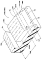
また、さらに好ましい態様としては、図6に示されるように、前記ショルダーブロック13bは、該ショルダーブロック13bのタイヤ軸方向外側の外壁面13bsと、該ショルダーブロック13bの踏面13bnと、前記ショルダー横溝9dに面するブロック壁面13bhとが交差する頂部13c1が三角形状の斜面17aで面取りされた面取り部17を有する切欠きブロック13B1を含む。これにより、図2に示されるように、ショルダー横溝9dには、タイヤ軸方向の外端側に溝幅W2が拡大する拡大部16が形成される。そして、例えばこの切欠きブロック13B1が、タイヤ周方向に連続して設けられるのが望ましい。このような切欠きブロック13B1を有する空気入りタイヤ1は、轍と接触し易い頂部13c1のエッジを面取りにて除去することにより、轍との接触時の応力をより効果的に分散することができ、耐ワンダリング性能をさらに向上させ得る。
Further, as a more preferable aspect, as shown in FIG. 6, the
上述の作用効果をより有効に発揮させるために、前記面取り部17のタイヤ周方向幅W5及びタイヤ軸方向幅W6は、いずれも、前記ショルダーブロック13bのタイヤ軸方向長さBWの好ましくは15%以上、より好ましくは20%以上が望ましく、また好ましくは30%以下、より好ましくは25%以下が望ましい。
In order to exhibit the above-described effects more effectively, the tire circumferential direction width W5 and the tire axial direction width W6 of the chamfered
また、図6に示されるように、切欠きブロック13B1には、前記細溝15と面取り部17とが併存して設けられるが、細溝15と面取り部17とのバットレス面14に沿った外表面距離L2は、5mm以上、より好ましくは6〜7mmであることが望ましい。これによって、細溝15と面取り部17との相乗効果が得られ、耐ワンダリング性能の向上をより一層図ることができる。
Further, as shown in FIG. 6, the notch block 13B1 is provided with the
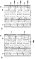
また、図7には、さらに本発明の他の実施形態が示される。
この実施形態では、前記ショルダーブロック13bは、前記外壁面13bsと、前記踏面13bnとが交差する周方向にのびる交差部13c2(2点鎖線で図示)がその全長さに亘って面取りされた矩形面17bからなる面取り部17を有する切欠きブロック13B2として形成される。このような切欠きブロック13B2は、前記踏面13bnのタイヤ軸方向長さBWが小さくなるため、轍に衝突し難くなり、ワンダりングの発生機会を低減させるのに役立つ。他方、このような、切欠きブロック13B2は、接地幅の減少を招くおそれがあるため、図8(a)に示されるように、ショルダーブロック列13Rにおいて、タイヤ周方向に一つおきに設けられるのが望ましい。これにより、接地面積の過度の減少を抑制できる。
FIG. 7 further shows another embodiment of the present invention.
In this embodiment, the
また、上述の作用効果を有効に発揮させるために、前記交差部13c2と前記踏面13bnとの面取り幅W7は、前記ショルダーブロック13bのタイヤ軸方向長さBWの、好ましくは15%以上、より好ましくは20%以上が望ましく、また好ましくは30%以下、より好ましくは25%以下が望ましい。
In order to effectively exhibit the above-described effects, the chamfering width W7 between the intersecting portion 13c2 and the tread surface 13bn is preferably 15% or more of the length BW in the tire axial direction of the
また、図8(b)に示されるように、ショルダーブロック列13Rにおいて、全てのショルダーブロック13bが、前記切欠きブロック13B2であっても良い。この場合、前記面取り幅W7は、前記ショルダーブロック13bのタイヤ軸方向長さBWの、好ましくは8%以上、より好ましくは12%以上が望ましく、また好ましくは20%以下、より好ましくは16%以下とし、面取り幅W7を図8(a)の態様の場合よりも小さくするが望ましい。これにより、各々のショルダーブロック13b(即ち、ショルダーブロック列13R)のブロック剛性が均一化され、偏摩耗の発生を抑制することができる。
Further, as shown in FIG. 8B, in the
また、前記切欠きブロック13B2に設けられた矩形状の斜面17bは、さらに耐ワンダリング性能を発揮させるために、タイヤ半径方向内方に向かって凸かつ曲率半径r2が8mm以上の凹曲面からなることが望ましい。このような凹曲面は、トレッド端Teを局部的に先鋭化し、変形させ易くすることでさらに耐ワンダリング性能を向上しうる。
Further, the rectangular
以上、本発明の実施形態について詳述したが、本発明は図示の実施形態に限定されることなく種々の態様に変形して実施しうる。 Although the embodiments of the present invention have been described in detail above, the present invention is not limited to the illustrated embodiments, and can be implemented in various forms.
本発明の効果を確認するために、図1の内部構造及び図2のパターンを有しかつ表1の仕様に基づいたタイヤサイズ195/65R15 91Qの乗用車用スタッドレスタイヤが試作された。そして、これらについて氷上制動性能、耐ワンダリング性能、耐クラック性能及び耐偏摩耗性能をテストをした。なお表1に示すパラメータ以外はすべて同一とした。また、本テストにおいて、W5とW6とは同じ長さとし、表1には代表してW5を記載した。主な共通仕様は次の通りである。 In order to confirm the effect of the present invention, a studless tire for a passenger car having a tire size of 195 / 65R15 91Q having the internal structure of FIG. 1 and the pattern of FIG. These were tested for ice braking performance, wandering resistance, crack resistance and uneven wear resistance. All parameters except those shown in Table 1 were the same. In this test, W5 and W6 have the same length, and Table 1 shows W5 as a representative. The main common specifications are as follows.
トレッド幅TW:185mm
ショルダー主溝の溝幅W2/TW:3.4%
ショルダー主溝の溝深さD2:8.9mm
ショルダー主溝の配設位置L1/TW:18%
細溝の溝幅W3/W2:65%
細溝の溝深さD3/D2:45%
細溝の領域H1:H×85%
ランド比:67%(比較例1)
テスト方法は次の通りである。
Tread width TW: 185mm
Shoulder main groove groove width W2 / TW: 3.4%
Shoulder main groove depth D2: 8.9 mm
Shoulder main groove placement position L1 / TW: 18%
Slot width W3 / W2 of narrow groove: 65%
Groove depth D3 / D2: 45%
Fine groove area H1: H x 85%
Land ratio: 67% (Comparative Example 1)
The test method is as follows.
<氷上制動性能>
試供タイヤを、リム(15×6.5J)に内圧(200kPa)で組み付け排気量1998cm3の国産FF車の全輪に装着して氷路面上をドライバー1名乗車の下で走行させ、走行速度30km/hから全輪ロック状態で制動してから車両が完全に停止するまでに要した制動距離を測定した。結果は、比較例1を100とする指数で表示した。数値が大きいほど良好である。なお各供試タイヤとも乾燥路面を100kmの慣らし走行した後で試験を行った。
<Ice braking performance>
A sample tire is assembled to a rim (15 x 6.5 J) with internal pressure (200 kPa) and mounted on all wheels of a domestic FF vehicle with a displacement of 1998 cm 3 and run on the icy road under a single driver. The braking distance required from the braking at 30 km / h until the vehicle completely stopped after braking in an all-wheel locked state was measured. The results were expressed as an index with Comparative Example 1 as 100. The larger the value, the better. Each test tire was tested after running on a dry road for 100 km.
<耐ワンダリング性能>
テストタイヤが全輪に装着された上記車両を、轍が設けられた氷雪路テストコースにて走行させた。そして、轍路面でのハンドルの取られ方などを重視して、耐ワンダリング性能がドライバーの官能評価により比較例1を100とする評点で評価された。数値が大きいほど良好である。
<Wandering resistance>
The vehicle with the test tires mounted on all the wheels was run on an icy and snowy road test course with a saddle. The wandering resistance was evaluated with a score of Comparative Example 1 as 100 based on the sensory evaluation of the driver, with emphasis on the way the handle is taken on the road surface. The larger the value, the better.
<耐クラック性能>
上記テストタイヤを15×6.5Jのリムに装着し、内圧200kPa、縦荷重4.62kN、速度100km/hで直径3mのドラム上を約30,000km走行させた。そして、細溝の溝底に発生したクラック数が測定された。結果は、実施例1を100とする指数とした。数値が小さい程、良好である。
<Crack resistance>
The test tire was mounted on a 15 × 6.5 J rim, and was run on a drum having a diameter of 3 m at an internal pressure of 200 kPa, a longitudinal load of 4.62 kN, and a speed of 100 km / h for about 30,000 km. The number of cracks generated at the bottom of the narrow groove was measured. The result was an index with Example 1 as 100. The smaller the value, the better.
<耐偏摩耗性能>
各試供タイヤを上記車両の前輪2輪に装着し走行したときのローテーション限界距離を測定した。結果は、比較例1を100とする指数とした。数値が大きい程、良好である。テストの結果を表1に示す。
<Uneven wear resistance>
The rotation limit distance was measured when each sample tire was run on the two front wheels of the vehicle. The result was an index with Comparative Example 1 as 100. The larger the value, the better. The test results are shown in Table 1.

テスト結果によると、本発明により、特に氷上制動性能と耐ワンダリング性能がともに向上しており、有意な発明であることが証明された。 According to the test results, both the braking performance on ice and the anti-wandering performance have been improved by the present invention, which proved to be a significant invention.
2 トレッド部
3 サイドウォール部
4 ビード部
5 ビードコア
6 カーカス
6n カーカスの法線
7 ベルト層
8c ショルダー主溝
14 バットレス面
15 細溝
15G 細溝の中心線
15e 細溝の中心線の延長線
e1 交点
Te トレッド端
2 Tread part 3
Claims (5)
正規リムに装着されかつ正規内圧が充填された無負荷である正規状態において、トレッド端間のトレッド幅TWとタイヤ最大幅SWとの比TW/SWが0.75〜0.95であり、
前記サイドウォール部のタイヤ半径方向の外方領域であるバットレス面には、タイヤ周方向に連続してのびる細溝が設けられるとともに、
前記正規状態におけるタイヤ回転軸を含むタイヤ子午線断面において、前記細溝の中心線と、該中心線の延長線と前記カーカスとが交差する交点を通るカーカスの法線とのなす角度が10度以内であり、
しかも前記トレッド部には、最もトレッド端側をタイヤ周方向に連続してのびる一対のショルダー主溝が設けられるともに、前記細溝の溝深さが、前記ショルダー主溝の溝深さの20〜50%であることを特徴とする空気入りタイヤ。 A pneumatic tire comprising a carcass extending from a tread portion through a sidewall portion to a bead core of a bead portion, and a belt layer disposed outside the carcass in the tire radial direction and inside the tread portion,
In the normal state in which the normal rim is mounted and the normal internal pressure is filled, the ratio TW / SW between the tread width TW between the tread ends and the tire maximum width SW is 0.75 to 0.95.
The buttress surface, which is an outer region in the tire radial direction of the sidewall portion, is provided with a narrow groove extending continuously in the tire circumferential direction,
In the tire meridian cross section including the tire rotation axis in the normal state, the angle formed by the center line of the narrow groove and the normal line of the carcass passing through the intersection of the extension of the center line and the carcass is within 10 degrees. And
In addition, the tread portion is provided with a pair of shoulder main grooves extending continuously in the tire circumferential direction at the tread end side, and the groove depth of the narrow groove is 20 to 20 times the groove depth of the shoulder main groove. A pneumatic tire characterized by being 50%.
前記ショルダーブロック列は、前記ショルダーブロックのタイヤ軸方向外側の外壁面と、該ショルダーブロックの踏面とが交差する交差部がその全長さに亘って面取りされた切欠きブロックが、タイヤ周方向に一つおきに設けられる請求項1乃至3のいずれかに記載の空気入りタイヤ。 The tread portion is provided with a shoulder block row in which a plurality of shoulder blocks are arranged in the tire circumferential direction by separating the shoulder lateral grooves extending between the shoulder main groove and the tread end in the tire circumferential direction.
The shoulder block row has a notch block in which a crossing portion where an outer wall surface on the outer side in the tire axial direction of the shoulder block intersects with a tread surface of the shoulder block is chamfered over the entire length thereof in the tire circumferential direction. The pneumatic tire according to any one of claims 1 to 3, provided every third.
前記ショルダーブロック列は、前記外壁面と、前記踏面と、前記ショルダー横溝に面するブロック壁面とが交差する頂部を三角形状の斜面で面取りされた切欠きブロックが、タイヤ周方向に連続して設けられる請求項1乃至3のいずれかに記載の空気入りタイヤ。 The tread portion is provided with a shoulder block row in which a plurality of shoulder blocks are arranged in the tire circumferential direction by separating the shoulder lateral grooves extending between the shoulder main groove and the tread end in the tire circumferential direction.
In the shoulder block row, a notch block having a chamfered crest with a triangular slope at the top where the outer wall surface, the tread surface, and the block wall surface facing the shoulder lateral groove intersect is provided continuously in the tire circumferential direction. The pneumatic tire according to any one of claims 1 to 3.
Priority Applications (3)
| Application Number | Priority Date | Filing Date | Title |
|---|---|---|---|
| JP2009257353A JP4996670B2 (en) | 2009-11-10 | 2009-11-10 | Pneumatic tire |
| KR1020100108143A KR20110052466A (en) | 2009-11-10 | 2010-11-02 | Pneumatic tire |
| CN201010537262.3A CN102049973B (en) | 2009-11-10 | 2010-11-08 | Pneumatic tire |
Applications Claiming Priority (1)
| Application Number | Priority Date | Filing Date | Title |
|---|---|---|---|
| JP2009257353A JP4996670B2 (en) | 2009-11-10 | 2009-11-10 | Pneumatic tire |
Publications (2)
| Publication Number | Publication Date |
|---|---|
| JP2011102073A true JP2011102073A (en) | 2011-05-26 |
| JP4996670B2 JP4996670B2 (en) | 2012-08-08 |
Family
ID=43954922
Family Applications (1)
| Application Number | Title | Priority Date | Filing Date |
|---|---|---|---|
| JP2009257353A Expired - Fee Related JP4996670B2 (en) | 2009-11-10 | 2009-11-10 | Pneumatic tire |
Country Status (3)
| Country | Link |
|---|---|
| JP (1) | JP4996670B2 (en) |
| KR (1) | KR20110052466A (en) |
| CN (1) | CN102049973B (en) |
Cited By (9)
| Publication number | Priority date | Publication date | Assignee | Title |
|---|---|---|---|---|
| JP2015061783A (en) * | 2014-11-26 | 2015-04-02 | 株式会社ブリヂストン | Tire |
| JP2016109249A (en) * | 2014-12-09 | 2016-06-20 | 三菱自動車工業株式会社 | Belt with groove |
| CN109532340A (en) * | 2018-12-25 | 2019-03-29 | 安徽佳通乘用子午线轮胎有限公司 | A kind of resistance to ditch splits low rolling resistance tire |
| US10868519B2 (en) | 2016-12-09 | 2020-12-15 | Micron Technology, Inc. | Apparatuses and methods for calibrating adjustable impedances of a semiconductor device |
| EP3831619A1 (en) * | 2019-12-04 | 2021-06-09 | Continental Reifen Deutschland GmbH | Pneumatic tyre |
| WO2021124969A1 (en) * | 2019-12-19 | 2021-06-24 | 株式会社ブリヂストン | Tire |
| CN114845889A (en) * | 2019-12-19 | 2022-08-02 | 株式会社普利司通 | Tyre for vehicle wheels |
| US11420482B2 (en) * | 2019-09-30 | 2022-08-23 | Toyo Tire Corporation | Pneumatic tire |
| CN114845889B (en) * | 2019-12-19 | 2024-04-26 | 株式会社普利司通 | Tire with a tire body |
Families Citing this family (7)
| Publication number | Priority date | Publication date | Assignee | Title |
|---|---|---|---|---|
| CN104271365B (en) * | 2012-06-27 | 2016-01-20 | 横滨橡胶株式会社 | Air-inflation tyre |
| FR3045466B1 (en) * | 2015-12-16 | 2017-12-22 | Michelin & Cie | PNEUMATIC HAVING IMPROVED WEAR AND ROLL RESISTANCE PROPERTIES |
| JP6838421B2 (en) * | 2017-02-16 | 2021-03-03 | 住友ゴム工業株式会社 | tire |
| CN108501621B (en) * | 2018-06-04 | 2024-01-23 | 青岛富耐特矿业科技有限公司 | High-performance special filling type solid tire |
| JPWO2020122169A1 (en) * | 2018-12-13 | 2021-10-28 | 株式会社ブリヂストン | Pneumatic tires |
| JP7181073B2 (en) * | 2018-12-14 | 2022-11-30 | Toyo Tire株式会社 | pneumatic tire |
| JP7298335B2 (en) * | 2019-06-25 | 2023-06-27 | 住友ゴム工業株式会社 | pneumatic tire |
Citations (5)
| Publication number | Priority date | Publication date | Assignee | Title |
|---|---|---|---|---|
| JPH0248202A (en) * | 1988-08-10 | 1990-02-19 | Yokohama Rubber Co Ltd:The | Pneumatic radial tyre |
| JPH05262105A (en) * | 1991-11-21 | 1993-10-12 | Sumitomo Rubber Ind Ltd | Pneumatic tire |
| JPH0687303A (en) * | 1992-09-09 | 1994-03-29 | Sumitomo Rubber Ind Ltd | Pneumatic tire |
| JP2000142027A (en) * | 1998-11-16 | 2000-05-23 | Bridgestone Corp | Pneumatic tire provided with shallow and narrow groove on buttress portion |
| JP2001180227A (en) * | 1999-12-24 | 2001-07-03 | Sumitomo Rubber Ind Ltd | Tire for heavy load |
Family Cites Families (2)
| Publication number | Priority date | Publication date | Assignee | Title |
|---|---|---|---|---|
| JP3365744B2 (en) * | 1999-04-01 | 2003-01-14 | 住友ゴム工業株式会社 | Pneumatic tire |
| JP4813230B2 (en) * | 2006-03-29 | 2011-11-09 | 東洋ゴム工業株式会社 | Pneumatic tire |
-
2009
- 2009-11-10 JP JP2009257353A patent/JP4996670B2/en not_active Expired - Fee Related
-
2010
- 2010-11-02 KR KR1020100108143A patent/KR20110052466A/en not_active Application Discontinuation
- 2010-11-08 CN CN201010537262.3A patent/CN102049973B/en not_active Expired - Fee Related
Patent Citations (5)
| Publication number | Priority date | Publication date | Assignee | Title |
|---|---|---|---|---|
| JPH0248202A (en) * | 1988-08-10 | 1990-02-19 | Yokohama Rubber Co Ltd:The | Pneumatic radial tyre |
| JPH05262105A (en) * | 1991-11-21 | 1993-10-12 | Sumitomo Rubber Ind Ltd | Pneumatic tire |
| JPH0687303A (en) * | 1992-09-09 | 1994-03-29 | Sumitomo Rubber Ind Ltd | Pneumatic tire |
| JP2000142027A (en) * | 1998-11-16 | 2000-05-23 | Bridgestone Corp | Pneumatic tire provided with shallow and narrow groove on buttress portion |
| JP2001180227A (en) * | 1999-12-24 | 2001-07-03 | Sumitomo Rubber Ind Ltd | Tire for heavy load |
Cited By (12)
| Publication number | Priority date | Publication date | Assignee | Title |
|---|---|---|---|---|
| JP2015061783A (en) * | 2014-11-26 | 2015-04-02 | 株式会社ブリヂストン | Tire |
| JP2016109249A (en) * | 2014-12-09 | 2016-06-20 | 三菱自動車工業株式会社 | Belt with groove |
| US10868519B2 (en) | 2016-12-09 | 2020-12-15 | Micron Technology, Inc. | Apparatuses and methods for calibrating adjustable impedances of a semiconductor device |
| CN109532340A (en) * | 2018-12-25 | 2019-03-29 | 安徽佳通乘用子午线轮胎有限公司 | A kind of resistance to ditch splits low rolling resistance tire |
| CN109532340B (en) * | 2018-12-25 | 2023-12-01 | 安徽佳通乘用子午线轮胎有限公司 | Trench crack resistant low rolling resistance tire |
| US11420482B2 (en) * | 2019-09-30 | 2022-08-23 | Toyo Tire Corporation | Pneumatic tire |
| EP3831619A1 (en) * | 2019-12-04 | 2021-06-09 | Continental Reifen Deutschland GmbH | Pneumatic tyre |
| WO2021124969A1 (en) * | 2019-12-19 | 2021-06-24 | 株式会社ブリヂストン | Tire |
| CN114845889A (en) * | 2019-12-19 | 2022-08-02 | 株式会社普利司通 | Tyre for vehicle wheels |
| CN114867617A (en) * | 2019-12-19 | 2022-08-05 | 株式会社普利司通 | Tyre for vehicle wheels |
| JP7431573B2 (en) | 2019-12-19 | 2024-02-15 | 株式会社ブリヂストン | tire |
| CN114845889B (en) * | 2019-12-19 | 2024-04-26 | 株式会社普利司通 | Tire with a tire body |
Also Published As
| Publication number | Publication date |
|---|---|
| CN102049973A (en) | 2011-05-11 |
| CN102049973B (en) | 2014-02-19 |
| JP4996670B2 (en) | 2012-08-08 |
| KR20110052466A (en) | 2011-05-18 |
Similar Documents
| Publication | Publication Date | Title |
|---|---|---|
| JP4996670B2 (en) | Pneumatic tire | |
| JP4338743B2 (en) | Pneumatic tire | |
| US10836215B2 (en) | Tire | |
| JP5265554B2 (en) | Pneumatic tire | |
| US10399390B2 (en) | Pneumatic tire | |
| JP5841568B2 (en) | Pneumatic tire | |
| JP5770834B2 (en) | Pneumatic tire for snow | |
| JP5973942B2 (en) | Pneumatic tire | |
| CN108688411B (en) | Pneumatic tire | |
| US10836216B2 (en) | Tire | |
| JP7187255B2 (en) | pneumatic tire | |
| JP4928785B2 (en) | Pneumatic tire | |
| JP7275834B2 (en) | tire | |
| CN106427402B (en) | Pneumatic tire | |
| JP5200123B2 (en) | Heavy duty pneumatic tire | |
| JP2023064576A (en) | tire | |
| JP2006297991A (en) | Pneumatic tire | |
| JP4751070B2 (en) | Pneumatic tire | |
| JP2003211920A (en) | Pneumatic tire | |
| JP6926780B2 (en) | tire | |
| JP7393632B2 (en) | tire | |
| JP4872066B2 (en) | Pneumatic tire | |
| US11518195B2 (en) | Off-road tyre | |
| JP7172106B2 (en) | tire | |
| JP7310434B2 (en) | tire |
Legal Events
| Date | Code | Title | Description |
|---|---|---|---|
| A131 | Notification of reasons for refusal |
Free format text: JAPANESE INTERMEDIATE CODE: A131 Effective date: 20110830 |
|
| A977 | Report on retrieval |
Free format text: JAPANESE INTERMEDIATE CODE: A971007 Effective date: 20110831 |
|
| A521 | Written amendment |
Free format text: JAPANESE INTERMEDIATE CODE: A523 Effective date: 20111026 |
|
| TRDD | Decision of grant or rejection written | ||
| A01 | Written decision to grant a patent or to grant a registration (utility model) |
Free format text: JAPANESE INTERMEDIATE CODE: A01 Effective date: 20120424 |
|
| A01 | Written decision to grant a patent or to grant a registration (utility model) |
Free format text: JAPANESE INTERMEDIATE CODE: A01 |
|
| A61 | First payment of annual fees (during grant procedure) |
Free format text: JAPANESE INTERMEDIATE CODE: A61 Effective date: 20120511 |
|
| FPAY | Renewal fee payment (event date is renewal date of database) |
Free format text: PAYMENT UNTIL: 20150518 Year of fee payment: 3 |
|
| R150 | Certificate of patent or registration of utility model |
Free format text: JAPANESE INTERMEDIATE CODE: R150 Ref document number: 4996670 Country of ref document: JP Free format text: JAPANESE INTERMEDIATE CODE: R150 |
|
| R250 | Receipt of annual fees |
Free format text: JAPANESE INTERMEDIATE CODE: R250 |
|
| R250 | Receipt of annual fees |
Free format text: JAPANESE INTERMEDIATE CODE: R250 |
|
| R250 | Receipt of annual fees |
Free format text: JAPANESE INTERMEDIATE CODE: R250 |
|
| R250 | Receipt of annual fees |
Free format text: JAPANESE INTERMEDIATE CODE: R250 |
|
| LAPS | Cancellation because of no payment of annual fees |