JP2011079110A - Machine tool - Google Patents
Machine tool Download PDFInfo
- Publication number
- JP2011079110A JP2011079110A JP2009235193A JP2009235193A JP2011079110A JP 2011079110 A JP2011079110 A JP 2011079110A JP 2009235193 A JP2009235193 A JP 2009235193A JP 2009235193 A JP2009235193 A JP 2009235193A JP 2011079110 A JP2011079110 A JP 2011079110A
- Authority
- JP
- Japan
- Prior art keywords
- workpiece
- headstock
- axis
- connecting pipe
- main shaft
- Prior art date
- Legal status (The legal status is an assumption and is not a legal conclusion. Google has not performed a legal analysis and makes no representation as to the accuracy of the status listed.)
- Pending
Links
Images
Landscapes
- Turning (AREA)
- Gripping On Spindles (AREA)
Abstract
【課題】軸方向に対して剛性が乏しいワークであっても、変形させないで把持して加工ができる第1主軸台および第2主軸台を備えた工作機械を提供する。
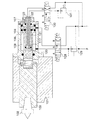
【解決手段】第1主軸台2と、刃物台21と、移動自在に、第1主軸台2に対向する第2主軸台12とを備え、前記第2主軸台12は、管状の第2主軸13と、第2主軸13に摺動自在に内挿された連結管19と、第2主軸13の先端部13aに固定され、とば口にテーパ穴15dが形成された貫通孔15cが設けられ、先端部15bに割溝15eが形成された開きヤトイ15と、テーパ穴15dに摺動自在に嵌合され、連結管19に連結されたテーパピン14と、連結管19の後方へ付勢してテーパピン14を介して開きヤトイ15を拡径するばね17と、ばね17の付勢力に抗して連結管19を前方へ押圧し、開きヤトイ15を縮径するピストン18bと、を備えたことを特徴とする工作機械30である。
【選択図】 図3Provided is a machine tool including a first spindle stock and a second spindle stock that can be gripped and processed without being deformed even with a workpiece having low rigidity in the axial direction.
A first headstock 2, a tool rest 21, and a second main headstock 12 that is movably opposed to the first mainhead stock 2, and the second main head stock 12 is a tubular second main shaft. 13, a connecting pipe 19 slidably inserted in the second main shaft 13, and a through-hole 15 c fixed to the tip end portion 13 a of the second main shaft 13 and having a tapered hole 15 d formed in the opening. , An open yatoe 15 having a split groove 15e formed at the tip 15b, a taper pin 14 that is slidably fitted into the tapered hole 15d and connected to the connecting pipe 19, and is biased to the rear of the connecting pipe 19. A spring 17 for expanding the diameter of the opening yatoy 15 via the taper pin 14, and a piston 18 b for pressing the connecting pipe 19 forward against the urging force of the spring 17 to reduce the diameter of the opening yatoy 15. The machine tool 30 is a feature.
[Selection] Figure 3
Description
本発明は、ワークの一端を把持する第1主軸台、および、ワークの他端を把持する第2主軸台を備えた工作機械に関する。 The present invention relates to a first spindle stock that grips one end of a workpiece and a machine tool including a second spindle stock that grips the other end of a workpiece.
オートマチック・トランスミッションの変速の為の油圧制御用バルブ、アンチロック・ブレーキ・システム作動用の油圧制御用バルブ、VTC(バルブタイミングコントロール)作動用の油圧制御用バルブ、CVT(Continuously Variable Transmission)作動用の油圧制御用バルブには、作動油を通すために複数本の溝が設けられ、結果として、軸方向やねじりに対して剛性が乏しい形状のスリーブが知られている。
図5は、スリーブ形状のワークWを示し、(a)は断面図、(b)は右側面図である。図5の(a)に示すように、ワークWは、全長は約70mm、フランジ部Wfの直径が約30mmであり、材質はアルミで形成されている。ワークWは、貫通孔eが穿設されてパイプ状に形成され、その先端部には拡径したねじ孔gに雌ねじが形成されている。また、ワークWの外周部には、油を通すために数箇所にクレバスのような大きな溝k、m、nが形成されている。この大きな溝k、m、nが、スリーブの剛性を低下させる最大の要因になっている。つまり、径方向の剛性はあるが、軸方向やねじりに対して剛性が乏しい。
Hydraulic control valve for automatic transmission shifting, hydraulic control valve for anti-lock brake system operation, hydraulic control valve for VTC (valve timing control) operation, CVT (Continuously Variable Transmission) operation A hydraulic control valve is provided with a plurality of grooves for allowing hydraulic oil to pass therethrough. As a result, a sleeve having a shape with poor rigidity in the axial direction and torsion is known.
5A and 5B show a sleeve-shaped work W, where FIG. 5A is a cross-sectional view and FIG. 5B is a right side view. As shown in FIG. 5A, the work W has a total length of about 70 mm, a flange portion Wf with a diameter of about 30 mm, and is made of aluminum. The workpiece W is formed in a pipe shape with a through hole e formed therein, and a female screw is formed in a screw hole g having an enlarged diameter at a tip portion thereof. In addition, large grooves k, m, and n like a crevasse are formed in the outer peripheral portion of the work W at several places to allow oil to pass therethrough. The large grooves k, m, and n are the largest factors that reduce the rigidity of the sleeve. That is, although there is radial rigidity, rigidity is poor with respect to the axial direction and torsion.
図6は、従来の技術である心押台のセンタを示す断面図である。図6に示すように、従来の心押台としては、心押台本体101にクイル103と、第1圧力室107と第2圧力室108を擁するシリンダ104を支持し、クイル103の先端部にはモールステーパによりテーパ合わせをした回りセンタ102が装着されている。また、このシリンダ104の内部にピストン106を収容し、そのピストン106をクイル103に連結するとともに、ピストン106の内側に第3圧力室120と第4圧力室121を形成する軸117を挿入し、かつ、軸の内部に第3圧力室120と第4圧力室121に連通する一対の油孔122,123を形成し、シリンダ104の油圧回路に第1切換弁128と第1減圧弁129を設けられている。軸117の油圧回路に第2切換弁130と第2減圧弁131を配置し、前記第1切換弁128と第2切換弁130により第1圧力室107と第4圧力室121の油圧を切換えできるように構成されたものが知られている。
この特徴は、一つのシリンダ104の内部に断面積が異なる四つの圧力室が形成されているので、第1切換弁128と第2切換弁130を切換えて各圧力室を適宜の組合せで加圧することにより、心押軸の推力が強〜弱の4段階に切換えることができることである。したがって、弱を選択すれば、ソフトタッチの押圧力に変換できる。
FIG. 6 is a cross-sectional view showing a center of a tailstock which is a conventional technique. As shown in FIG. 6, as a conventional tailstock, the
This feature is because four pressure chambers having different cross-sectional areas are formed in one
しかしながら、前記ワークWは軸方向に対して剛性が乏しいため、ソフトタッチのセンタであっても小さな押圧力によりワークが変形し、円筒度、真円度の指定寸法公差から外れて不良品になるという問題があった。 However, since the workpiece W has poor rigidity in the axial direction, even if it is a soft touch center, the workpiece is deformed by a small pressing force, and becomes a defective product outside the specified dimensional tolerances of cylindricity and roundness. There was a problem.
そこで、本発明は、これらの問題点に鑑みてなされたもので、軸方向やねじりに対して剛性が乏しいワーク(スリーブ)を加工する工作機械であって、ワークを変形させないでワークを把持して加工ができる第1主軸台および第2主軸台を備えた工作機械を提供することを課題とする。 Therefore, the present invention has been made in view of these problems, and is a machine tool for machining a work (sleeve) having poor rigidity in the axial direction and torsion, and grips the work without deforming the work. It is an object of the present invention to provide a machine tool including a first spindle stock and a second spindle stock that can be machined.
請求項1に記載の発明は、ベッド(1)に配置され、ワーク(W)の一端部を把持して回転させる第1主軸台(2)と、数値制御によって前記ベッド(1)に移動自在に配設された刃物台(21)と、前記ベッド(1)に移動自在に、かつ前記第1主軸台(2)に対向して設けられ、前記ワーク(W)の他端部を把持して回転させる第2主軸台(12)と、を備えた工作機械(30)であって、前記第2主軸台(12)は、管状の第2主軸(13)と、前記第2主軸(13)に摺動自在に内挿された連結管(19)と、前記第2主軸(13)の先端部(13a)に固定され、とば口にテーパ穴(15d)が形成された貫通孔(15c)が設けられ、先端部(15b)に割溝(15e)が形成された開きヤトイ(15)と、前記テーパ穴(15d)に摺動自在に嵌合され、前記連結管(19)に連結されたテーパピン(14)と、前記連結管(19)の後方へ付勢して前記テーパピン(14)を介して前記開きヤトイ(15)を拡径するばね(17)と、前記ばね(17)の付勢力に抗して前記連結管(19)を前方へ押圧し、前記開きヤトイ(15)を縮径するピストン(18b)と、を備えたことを特徴とする。 The invention according to claim 1 is arranged on the bed (1), and can move to the bed (1) by numerical control and a first headstock (2) that grips and rotates one end of the work (W). A tool post (21) disposed on the bed (1), movably on the bed (1) and facing the first spindle stock (2), and grips the other end of the workpiece (W). A machine tool (30) provided with a second spindle stock (12) to be rotated, wherein the second spindle stock (12) comprises a tubular second spindle (13) and the second spindle (13). ) Slidably inserted in the connecting pipe (19), and a through hole (15d) formed at the end of the second main shaft (13) with a tapered hole (15d) fixed thereto. 15c), an open yatoe (15) in which a split groove (15e) is formed at the tip (15b), and the tapered hole (15 ) And a taper pin (14) slidably fitted to the connecting pipe (19), and urged toward the rear of the connecting pipe (19) to open the opening pin through the taper pin (14). A spring (17) that expands the diameter of (15), and a piston (18b) that presses the connecting pipe (19) forward against the urging force of the spring (17) and reduces the diameter of the opening yatoy (15). ).
請求項2に記載の発明は、請求項1に記載された工作機械(30)であって、前記第1主軸台(2)には、コレットチャック(4)が装着され、前記コレットチャック(4)のコレット(5)の前端面に、ワーク(W)の一端部を把持するための窪み(5c)が設けられたことを特徴とする。
The invention according to
請求項1に係る発明によれば、第2主軸台に装着された開きヤトイにより、ワークの他端部に設けられたねじ穴に、開きヤトイの先端部が嵌入されて拡径され、把持できる。その結果、テールストックに見られるような押圧力を全く発生させずにワークの他端部を把持することができるため、軸方向に対して剛性が乏しいワークであってもワークを変形させることがない、また、精度のよい加工ができる。 According to the first aspect of the present invention, the opening yatoy mounted on the second headstock is inserted into the screw hole provided in the other end of the workpiece, and the tip of the opening yatoi is expanded to be gripped. . As a result, it is possible to grip the other end of the workpiece without generating any pressing force as seen in the tailstock, so that the workpiece can be deformed even if the workpiece has poor rigidity in the axial direction. It can be processed with high accuracy.
請求項2に係る発明によれば、第1主軸台に装着されたコレットチャックのコレットの前端面に窪みが設けられたことにより、ワークの一端を把持するときに、同時にワークを後方へ引き込む動作が発生するため、ワークをストッパへ押し当てながら把持することができる。そのため、テールストックによる押圧力がなくても、ワーク端面とチャック端面との間の隙間が生じないため、長手方向の寸法は、精度よく加工することができる。 According to the second aspect of the present invention, since the recess is provided in the front end surface of the collet chuck mounted on the first headstock, when the workpiece is gripped at one end, the workpiece is simultaneously pulled backward. Therefore, the workpiece can be held while being pressed against the stopper. Therefore, a gap between the workpiece end surface and the chuck end surface does not occur even if there is no pressing force by the tailstock, and therefore the dimension in the longitudinal direction can be processed with high accuracy.
以下、本発明の実施の形態を、図面を参照しながら説明する。
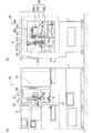
図1の(a)に示すように、工作機械30は、例えば、ターニングセンタ30であり、3軸(XYZ)制御の刃物台21を有し、対向する2スピンドル仕様になっており、対向主軸形のターニングセンタである。第1主軸台2は、ベッド1の左端部の上面に固定され、図示しない第1スピンドルモータによって第1主軸3(図2参照)が駆動回転される。
第2主軸台12は、ベッド1の正面座に固定されたスライドガイド1aの上面に載置され、左右(W軸)方向へ摺動自在に配置されている。第2主軸台12の第2スピンドルモータ12m(図1(b)参照)は、第1主軸3の第1スピンドルモータと同じモータが設けられており、高速での同期回転ができる。
なお、工作機械の座標系を示す記号についてはJISB6310に規定されている。横形旋盤に関しては、主軸台の主軸の軸(前後)方向をZ軸とし、このZ軸に直交する(左右)方向はX軸、Z軸とX軸に直交する上下方向はY軸、また、第2主軸台の移動方向はW軸、Z軸の軸周りはC軸、と規定されている。
Hereinafter, embodiments of the present invention will be described with reference to the drawings.
As shown in FIG. 1A, a
The
The symbols indicating the coordinate system of the machine tool are defined in JIS B6310. For horizontal lathes, the axis (front / rear) direction of the main shaft of the headstock is the Z axis, the (right / left) direction perpendicular to the Z axis is the X axis, the vertical direction perpendicular to the Z axis and the X axis is the Y axis, The moving direction of the second headstock is defined as the W axis, and the circumference of the Z axis is defined as the C axis.
本発明のターニングセンタ30の制御軸数は、3(XZY)軸と、第1主軸3の回転割出およびエンドミルによるコンタリング加工を可能にするC軸、それに第2主軸台12の左右方向へ移動するW軸の計5軸であり、ほかに2つの主軸が同期回転制御されている。
図1の(a)に示すように、立クロススライド29は、刃物台21を固定する板状のスライドである。Z軸(主軸の軸)方向の移動は、図示しないサドルとZ軸移動機構で行い、X軸(前後)方向の移動は、図示しないL形クロススライドとX軸移動機構で行い、と、Y軸(上下)方向へ移動は、前記立クロススライド29と後記するY軸移動機構で行う。刃物台21は、外径工具用櫛刃形刃物台21aと内径工具用櫛刃形刃物台21bとから構成されている。立クロススライド29の左側面には外径工具用櫛刃形刃物台21aが固定され、正面には内径工具用櫛刃形刃物台21bが固定されている。
さらに、回転工具のドリル24とエンドミル25が立クロススライド29の左側正面に固定されている。
機械本体の3(XYZ)軸の移動は、前記X軸移動機構、前記Z軸移動機構、前記Y軸移動機構により行われる。ここでは、Y軸移動機構を詳細に説明し、その他の軸、例えばX軸移動機構、Z軸移動機構については、本出願人が先に出願した特許3697259号公報に記載されているため、詳細な説明は省略する。
The number of control axes of the
As shown in FIG. 1A, the standing
Further, a
The 3 (XYZ) axis of the machine body is moved by the X-axis movement mechanism, the Z-axis movement mechanism, and the Y-axis movement mechanism. Here, the Y-axis moving mechanism will be described in detail, and the other axes, for example, the X-axis moving mechanism and the Z-axis moving mechanism are described in Japanese Patent No. 3697259 filed earlier by the present applicant. The detailed explanation is omitted.
<Y軸移動機構>
図1の(b)に示すように、Y軸移動機構28は、立クロススライド29を上下(Y軸)方向へ移動させるための駆動装置である。Y軸移動機構28は、一対のY軸用すべりガイド29a,29a(図4参照)の間の凹部に配置され、Y軸用ボールねじ28aと、このY軸用ボールねじ28aに螺入したY軸用ナット28bと、Y軸用ボールねじ28aに固定したプーリ28cと歯付ベルト28dを介して連結されたY軸用サーボモータ28mとから構成され、Y軸用サーボモータ28mの回転が伝達される。また、Y軸用すべりガイド29a,29aの形状はダブテールになっているが、ころがりガイドにしてもよい。
<Y-axis moving mechanism>
As shown in FIG. 1B, the Y-
<外径工具用櫛刃形刃物台>
図1の(b)に示すように、外径工具用櫛刃形刃物台21aは、立クロススライド29(図1の(a)の正面視では左側面)に固定されて配設されている。外径工具とは外径バイト22を指している。外径工具用櫛刃形刃物台21aは、例えば、5本の溝が形成されており、5本の外径バイト22,22…が装着できる。この外径バイト22の選択は、Y軸(上下方向)制御により行い、上下動だけで外径バイト22の選択が可能である。
<Combination tool post for outer diameter tools>
As shown in FIG. 1 (b), a comb
<内径工具用櫛刃形刃物台>
図1の(a)に示すように、内径工具用櫛刃形刃物台21bは、立クロススライド29の正面の左側に固定されて配設されている。内径工具とは主にボーリングバーや内径溝入れ工具等を指している。ボーリングバー23は、例えば、3本の固定穴が形成されており、3本のボーリングバー23,23…が装着できる。このボーリングバー23の選択は、Y軸制御により行い、上下動で内径工具23の選択ができる。
<Combine tool post for inner diameter tool>
As shown in FIG. 1A, the inner diameter tool comb-shaped
以上の通り、ターニングセンタ30は、立クロススライド29の移動を3軸構成にしたことにより、立クロススライド29に固定された外径工具用櫛刃形刃物台21aと内径工具用櫛刃形刃物台21bは、Y軸による移動により工具の選定ができるため、一種の自動工具交換装置(ATC)であり、ツールを格納したツールマガジン装置となっている。また、ドリルやエンドミル等の回転工具の切削送りは、Y軸移動で可能になることから、これまでの2軸構成のNC旋盤では加工ができないミーリング加工、例えば、Z,X軸から芯が外れた位置への穴明け、タップ加工、Dカット等の複合加工が容易にできるため、従来の2軸構成のNC旋盤では加工できなかったワークの取り込みができる。
As described above, the turning
<第1主軸台>
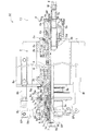
図2に示すように、第1主軸台2には、ワークWの一端であるフランジ部Wfを把持する第1ワーク把持装置10が装着されている。第1主軸3の後端部3bには回転を伝えるプーリ6が固定されている。別置に設けられた第1スピンドルモータ(図示せず)の回転が歯付ベルト6aを介して伝達されて高速回転する。また、第1主軸3には小径の第2プーリ6bが装着され、ナット6nによって固定されている。この第2プーリ6bには、歯付ベルトを介して回転数を検知するポジションコーダ(図示せず)が設けられている。
<First headstock>
As shown in FIG. 2, a first
<第1ワーク把持装置>
第1ワーク把持装置10は、この第1主軸3に主に装着されている。
第1主軸3は、管状に形成され、第1主軸台本体2aにベアリング2b,2b…を介して両端支持され、回転自在に軸支されている。
第1主軸3の先端部3aには、コレットチャック4が装着されている。
コレットチャック4のチャックボディ4aには、軸心に沿って貫通孔4bが設けられている。この貫通孔4bにはテーパ穴部4cが設けられている。そして、このテーパ穴部4cにはコレット5のテーパ部5aが嵌合されて挿着されている。
さらに、コレット5の前端面には、ワークWのフランジ部Wfを把持するための窪み5cが設けられ、また、テーパ部5aはスリット状の3つの割溝5bが形成されている。
この割溝5bのスリットのスペースには、ワークWの端面と当接するストッパ4dが設けられている。また、コレット5の後端部5dは、連結管9の先端部9aに一体に螺合されている。
<First workpiece gripping device>
The first
The first
A
A through-
Further, the front end surface of the
A
また、第1主軸台本体2aにプレート8gが固定され、このプレート8gにシリンダ8aが配設されている。また、シリンダ8aのシリンダロッド8bの先端部にジョイント8cが接続され、このジョイント8cの先端にはリンク8dの一端が第1ピン8P1によって回動自在に接続されている。
シリンダ8aは、高圧エアまたは油圧用であり、第1主軸台2の上部または後方に固定されている。
リンク8dは、一端が回動自在にジョイント8cに支持され、他端が第1主軸台本体2aに固定されたステー8fが延設され、この先端に回動の支点となる第2ピン8P2によって回動自在に接続され、シフタ8の2つのピン部8Pとも回転自在に係合している。
A
The
シフタ8は、スリーブ7eのつば部7fに遊嵌して配置されている。
シフタ8は、リング状に形成され、前記スリーブ7eが第1主軸3と一緒に回転しても支障がないように内周面にリング状の大きな溝が形成されている。また、シフタ8の外周には、主軸の軸線位置に対向して2個のピン部8P,8Pが突設され、このピン部8P,8Pが、前記リンク8d,8dに設けられた通し穴に回転自在に嵌入されている。
The
The
これにより、図2に示すように、図中下の第2ピン8P2を支点にしてリンク8dが左(後方)へ傾くと、シフタ8を介してスリーブ7eが左へ移動し、ボール7bを後記するV溝に押し込む。その反対に第2ピン8P2を支点にしてリンク8dが右(前方)へ傾くと、シフタ8を介してスリーブ7eが右へ移動し、後記する逃がし溝7iがボール7bを回収し保持する。このように、ボール7bの出し入れをすることにより、ワークWをクランプ、または、アンクランプする伝達機構が装着されている。
つづいて、このクランプ・アンクランプ動作をする伝達機構を説明する。
Thus, as shown in FIG. 2, when the
Next, a transmission mechanism that performs this clamping / unclamping operation will be described.
<クランプ・アンクランプ動作の伝達機構>
第1主軸3の最後端部3cには、第1スリーブ7aと第2スリーブ7cが配置されている。第1スリーブ7aと第2スリーブ7cの当接面側の端面において、第1スリーブ7aの端面にはテーパ部が設けられ、片側のみ傾斜面で非対称であるが、結果としてV溝が形成されている。
第2スリーブ7cはキー7kにより主軸の最後端部3cに回転が規制され、軸方向への摺動は自在とされている。
ボール7bは、第1スリーブ7aと第2スリーブ7cの間のV溝に6個が6等分に分割した配置で挟持される。
スリーブ7eは、第1スリーブ7aと第2スリーブ7cの外周に摺動自在に嵌合されており、内周面には拡径して設けられた前記ボール7bの逃がし溝7iが6箇所形成され、外周面にはつば部7fが突設され、第2スリーブ7cとは一体で軸方向に摺動自在になるキー7kが装着されている。
つば状係止部材7は、最後端部に設けられ、内周面に雌ねじが形成され、連結管9の後端部9bに螺入されている。つば状係止部材7の外周面には、つば状部7hが形成されている。つば状部7hには第2スリーブ7cの端面が押し当てられ、変形ナット7nによって一体に固定されている。
変形ナット7nは、前記第2スリーブ7cに螺入され、かつ、つば状係止部材7のつば状部7hを後方から挟持して一体になっている。
<Clamping / unclamping transmission mechanism>
A
The rotation of the
The
The
The collar-shaped
The
<クランプ動作>
シリンダ8aの右端部に高圧エアまたは油圧が流入すると、ピストンロッド8bは伸張し、リンク8dが第2ピン8P2を支点にして左方向へ傾き、同時にシフタ8を左方向へ移動させる。そうすると、スリーブ7eも左方向へ移動し、逃がし溝7i内のボール7bはV溝へ強制的に押し込められる。その結果、図2に示すように、ボール7bがV溝に押し込められると、V溝の傾斜面とボール7bにより、第2スリーブ7cの位置は後方へ移動し、第2スリーブ7cがつば状係止部材7のつば状部7hを押圧し、つば状係止部材7が連結管9を後方へ引張り、連結管9の先端部9aに接続したコレット5を後方へ引張り、コレットチャック4のテーパ穴4cによってコレット5を縮径させ、ワークWをクランプする。
<Clamping action>
When high-pressure air or hydraulic pressure to the right end portion of the
<アンクランプ動作>
シリンダ8aの左端に高圧エアまたは油圧が流入すると、ピストンロッド8bは短縮し、第2ピン8P2を支点にしてリンク8dを右方向へ傾かせ、同時にシフタ8を右方向へ移動させる。そうすると、シフタ8に遊嵌されたつば部7fのスリーブ7eが、右方向へ移動し、V溝に押し込まれたボール7bを逃がし溝7iに回収される。その結果、第2スリーブ7cによるつば状係止部材7のつば状部7hへの押圧動作はなくなり、つば状係止部材7が連結管9を後方へ引張る引張りもなくなり、連結管9の先端部9aに接続したコレット5を後方への引張りもなくなり、コレットチャック4のテーパ穴部4cによるコレット5の縮径もなくなり、コレット5の縮径が弾性により元に戻り、コレット5は拡径してワークWをアンクランプする。
<Unclamping action>
When high-pressure air or hydraulic pressure to the left end of the
<第2主軸台>
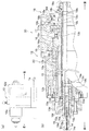
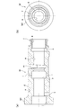
図3に示すように、第2主軸台12には、ワークWの他端部を把持する第2ワーク把持装置20が装着されている。第2主軸13は、管状に形成され、先端部13aにはフランジ形状になっており、後端部13bにはプーリ16が、ナット16nによって固定されている。また、第2主軸台ボディ12aの外周に固定された第2スピンドルモータ12m(図1参照)の回転がベルト16aを介して伝達され、前記した第1主軸台2の第1スピンドルモータと、この第2スピンドルモータ12mとは、回転速度が同期回転する。
<Second headstock>
As shown in FIG. 3, a second
<第2ワーク把持装置>
図3に示すように、第2ワーク把持装置20は、第2主軸台12にベアリング12b,12b…を介して両端軸支され、回転自在に軸支された第2主軸13に装着されている。第2主軸13は、後端部13bに配置されたプーリ16の後方の、最後端部13cには後記するシリンダ18が形成されている。また、第2主軸13の先端部13aには開きヤトイ15が装着されている。
<Second workpiece gripping device>
As shown in FIG. 3, the second
<開きヤトイ>
開きヤトイ15は、第2主軸13の最先端部に配置されている。
アダプタ13dは、第2主軸13の先端部13aのフランジ部にボルトによって固定されている。アダプタ13dの端面には、窪みが形成されている。
ソケット15fはこのアダプタ13dの端面の窪みにボルトによって固定されている。ソケット15fの内周面は、片角20度のテーパが形成されている。
開きヤトイ15の外周部15aは、このソケット15fの内周面に設けられた片角20度のテーパ面に合わせた雄型に形成されて嵌入している。また、先端部15bはワークWの先他端部に形成されたねじ穴の内径に合わせて挿入できるサイズに縮径され、軸中心には貫通孔15cが設けられ、貫通孔15cの先端部には、90度のテーパ部15dが形成され、3つの割溝15eのスリットが形成されている。この開きヤトイ15は、弾性変形を利用した固定具であるが、第1主軸3のコレット5とは異なり、正反対の動きである。
<Open Yatoi>
The
The
The
The outer
また、連結管19の先端部19aにはジョイント19cが螺入され、アダプタ13dから回り止め用のキー13kが設けられ、ジョイント19cとの回転方向のずれが起きないようになっている。
ジョイント19cの内径にはスタットボルト状の棒状ジョイント19dが螺入され、ナット19nにてロックされている。また、この棒状ジョイント19dの先端部に設けられた雌ねじが設けられ、テーパピン14が螺入されている。
<テーパピン>
テーパピン14の頭部は、サラ小ねじのような90度のテーパ部14aが設けられ、このテーパ部14aが開きヤトイ15の貫通孔15cのとば口に設けられた90度のテーパ部15dに嵌合されている。さらに、テーパピン14の後端部14bは、棒状ジョイント19dの先端部に螺入されている。
In addition, a joint 19c is screwed into the
A stat bolt-like rod-shaped joint 19d is screwed into the inner diameter of the joint 19c and is locked by a
<Taper pin>
The head part of the
図3に示すように、第2ワーク把持装置20は、第2主軸13の先端部13aには前記開きヤトイ15が設けられ、第2主軸13の最後端部13cにはシリンダ18が設けられている。また、連結管19の後端部19bには、第2主軸台本体12aに内蔵されたシリンダ18のピストン18bの力を利用して、ワークWをクランプ・アンクランプ動作する伝達機構が装着されている。
As shown in FIG. 3, the second
<クランプ・アンクランプ動作の伝達機構>
第2主軸13の後端部13bに設けられたプーリ16の後方には、連結管19を後方へ付勢する皿ばね17が2枚設けられ、当て金17aと変形ナット18nと、係止部材19eが連結管19の後端部19bに螺着されており、この係止部材19eに皿ばね17の付勢力が伝達されるようになっている。
当て金17aは、図3に示すように、断面形状がクランク状に形成され、カバー12cの内周面に平行に設けられて皿ばね17の外周を支持し、今度は直角に曲がり、皿ばね17の厚みの軸方向を支持しており、最後に、また、軸方向へ屈曲して第2主軸13の最後端部13cに嵌合されて軸方向へ摺動自在になっている。
ケース12dは、円筒スリーブ形状に形成され、第2主軸台ボディ12aの後方の外周面に固定されている。このケース12dの内周面には、断面がL型のサイドケース18aとエンドカバー18dが配置され、その間を前後に摺動自在のピストン18bが配置され、シリンダ18が構成されている。
<Clamping / unclamping transmission mechanism>
Two disc springs 17 for urging the connecting
As shown in FIG. 3, the
The
<クランプ動作>
図3に示すように、皿ばね17の付勢力によってクランプする。
シリンダ18のピストン18bの左端側(一方)から高圧エアまたは油圧が流入すると、ピストン18bの押圧部18cは当て金17aから離間して後方(右)へ待機する。そこで、2枚の皿ばね17の付勢力によって当て金17aを後方に移動させ、この当て金17aが係止部材19eを押圧し、連結管19を後方へ付勢する。この結果、連結管19の先端部19aに接続されたテーパピン14を後方へ引張るため、開きヤトイ15の先端部15bが拡径してワークWをクランプする。
<Clamping action>
As shown in FIG. 3, it clamps with the urging | biasing force of the
When high-pressure air or hydraulic pressure flows from the left end side (one side) of the
<アンクランプ動作>
図3に示すように、皿ばね17の付勢力に抗して撓ませ、アンクランプする。
シリンダ18の右端側(他方)から高圧エアまたは油圧が流入すると、ピストン18bが前進(左方向へ移動)し、押圧部18cが当て金17aを押圧し、皿ばね17の付勢力に抗して皿ばね17を撓ませる。そして、この当て金17aが係止部材19を前進させ、連結管19を前方へ前進させる。その結果、連結管19の先端部19aに接続されたテーパピン14も前進させるため、テーパ部15dの係合がゆるみ、開きヤトイ15の先端部15aは弾性により元の形状に縮径してもどり、ワークWをアンクランプする。
<Unclamping action>
As shown in FIG. 3, the
When high-pressure air or hydraulic pressure flows from the right end side (the other side) of the
<ワーク把持方法及び加工方法>
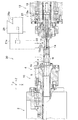
図4に示すように、第1主軸台2にコレットチャック4の第1ワーク把持装置10を設け、第2主軸台12に開きヤトイの第2ワーク把持装置20を設けたターニングセンタ30のワーク把持方法を説明し、合わせて加工方法を説明する。
1)第1工程は、第1主軸台2のコレットチャック4のコレット5がワークWの一端を把持する。
第1ワーク把持装置10において、コレットチャック4のコレット5を拡径してアンクランプ状態にし、ワークWのフランジ部Wfを把持し、クランプの起動ボタンを押す。
そうすると、図2に示すように、シリンダ8aのシリンダロッド8bが伸張し、連結管9が後方に引張られ、チャックボディ4aのテーパ穴4cにより、コレット5が縮径して、ワークWが引き込まれ、コレットチャック4のストッパ4dにワークWの端面を押付けながら、ワークWのフランジ部Wfをクランプする。
2)第2工程は、第2主軸台12に開きヤトイ15の第2ワーク把持装置20を設け、ワークWの他端を把持する。図4に示すように、ワークWの他端の先端部に設けられた雌ねじを加工する前のねじ穴gに、第2主軸台12の開きヤトイ15の先端部15bを縮径したアンクランプ状態にして挿入する。そして、第2主軸台12のクランプの起動ボタンを押す。
そうすると、連結管19の先端部19aに接続されたテーパピン14が後方へ引張られ、開きヤトイ15の先端部15aが拡径し、ワークWの他端部をクランプする。
<Work gripping method and processing method>
As shown in FIG. 4, the workpiece gripping of the
1) In the first step, the
In the first
Then, as shown in FIG. 2, the
2) In the second step, the second
If it does so, the
<切削加工の開始>
3)第3工程は、外径仕上げ加工を行う。
第1主軸台2の第1スピンドルモータ、および、第2主軸台12の第2スピンドルモータ12m(図1(b)参照)が同期回転して所定の高速回転になると、図4に示すように、外径バイト用櫛刃形刃物台21aに固定された5本のうち、1本の外径バイト22が、(予め使用する外径バイト22の順番はNCプログラムに入力されている。)NCプログラムによりY軸(上下)方向の移動によって選定される。
外径バイト22は、X軸(前後)方向と、Z軸(左右)方向へ移動しながら、往復移動を繰り返し、所定の外径寸法で加工し、元の位置にもどる。
4)第4工程は、エンドミル25により外径溝Pを加工する。
図1の(b)に示すように、Y軸方向に設けられたエンドミル25を回転させ、Y、X、Z軸の移動によりワークWの加工箇所に移動し切り込み、第1主軸台2と、第2主軸台12のC軸制御によりDカットのコンタリング加工を行い、元の位置にもどる。
5)第5工程は、ドリル24により、例えばφ0.5mm穴を開ける。
図1の(b)に示すように、第1主軸台2の第1主軸3は停止し、ロック板6c(図2参照)に図示しないクサビが入りロックされ、第2主軸台12の第2主軸13も停止する。Y軸方向に設けられたドリル24を回転させ、Y、X、Z軸の移動によりワークWの加工箇所に移動し切り込み、小穴の通し加工を行い、元の位置にもどる。
6)第6工程は、第2主軸台12を待機位置に後退させる。
第2主軸台12の開きヤトイ15を縮径するアンクランプ状態にして、第2主軸台12を右端に後退させて待機する。
7)第7工程は、ボーリングバー23により、雌ねじの小径と通し穴を加工する。
内径工具用櫛刃形刃物台21bに固定されたボーリングバー23がY軸(上下)方向の移動によりボーリングバー23が選定され、X軸(前後)方向と、Z軸(左右)方向へ移動しながら、所定の内径寸法で加工し、元の位置にもどる。
8)第8工程は、タップ26により例えばM16ネジを加工する。
内径工具用櫛刃形刃物台21bに固定されたタップ26がY軸(上下)方向の移動により選定され、X軸(前後)方向と、Z軸(左右)方向へ移動しながら、所定のM16ネジ加工をして、元の位置にもどる。
<Start of cutting>
3) In the third step, outer diameter finishing is performed.
When the first spindle motor of the
The
4) In the fourth step, the outer diameter groove P is processed by the
As shown in FIG. 1 (b), the
5) In the fifth step, for example, a hole of φ0.5 mm is formed by the
As shown in FIG. 1 (b), the
6) In the sixth step, the
The unclamping state in which the
7) In the seventh step, the small diameter of the internal thread and the through hole are processed by the
The
8) In the eighth step, for example, an M16 screw is processed by the tap 26.
The tap 26 fixed to the comb-
9)第9工程は、ワークWを開放する。
アンクランプの起動ボタンを押し、第1主軸台2のコレット5の先端部をアンクランプ状態にして拡径し、ワークWのフランジ部Wfを開放し、ワークWを開放する。
この第1〜9工程を含む工程により、ターニングセンタ30による加工が終了する。
9) In the ninth step, the workpiece W is released.
An unclamping start button is pressed, the tip of the
By the steps including the first to ninth steps, the machining by the turning
なお、本発明はその技術思想の範囲内で種々の改造、変更が可能である。例えば、5軸制御のターニングセンタ30の第1主軸台2と第2主軸台12として説明したが、Y軸を割愛したNC旋盤31の第1主軸台2と第2主軸台12としても構わない。
The present invention can be modified and changed in various ways within the scope of the technical idea. For example, the
1 ベッド
1a スライドガイド
2 第1主軸台
2a 第1主軸台本体
2b ベアリング
3 第1主軸
3a 先端部
3b 後端部
3c 最後端部
4 コレットチャック
4a チャックボディ
4b 貫通孔
4c テーパ穴部
4d ストッパ
5 コレット
5a テーパ部
5b 3つ割溝
5c 窪み
5d 後端部
6 プーリ
6a 歯付ベルト
6b 第2プーリ
6c ロック板
6n ナット
7 つば状係止部材
7a 第1スリーブ
7b ボール
7c 第2スリーブ
7k キー
7e スリーブ
7f つば部
7h つば状部
7i 逃がし溝
7n 変形ナット
8 シフタ
8a シリンダ
8b ピストンロッド
8c ジョイント
8d リンク
8e ピン穴
8f ステー
8g プレート
8P ピン部
8P1 第1ピン
8P2 第2ピン
9 連結管
9a 前端部
9b 後端部
10 第1ワーク把持装置(コレットチャック)
12 第2主軸台
12a 第2主軸台ボディ
12b ベアリング
12c カバー
12d ケース
12m 第2スピンドルモータ
13 第2主軸
13a 先端部
13b 後端部
13c 最後端部
13d アダプタ
13k キー
14 テーパピン
14a テーパ部
14b ねじ部
15 開きヤトイ
15a 外周部
15b 先端部
15c 貫通孔
15d テーパ部
15e 3つ割溝
15f フランジ部
16 プーリ
16a ベルト
16n ナット
17 皿ばね
17a 当て金
18 シリンダ装置
18a サイドケース
18b ピストン
18c 押圧部
18d エンドカバー
18n 変形ナット
19 連結管
19a 先端部
19b 後端部
19c ジョイント
19d 棒状ジョイント
19e 係止部材
19n ナット
20 第2ワーク把持装置(開きヤトイ)
21 刃物台
21a 外径工具用櫛刃形刃物台
21b 内径工具用櫛刃形刃物台
22 外径バイト
23 ボーリングバー
24 ドリル
25 エンドミル
26 タップ
28 Y軸移動機構
28a Y軸用ボールねじ
28b Y軸用ナット
28c プーリ
28d 歯付ベルト
28m Y軸用サーボモータ
29 立クロススライド
29a Y軸用すべりガイド
30 工作機械
DESCRIPTION OF SYMBOLS 1
12
21
Claims (2)
数値制御によって前記ベッド(1)に移動自在に配設された刃物台(21)と、
前記ベッド(1)に移動自在に、かつ前記第1主軸台(2)に対向して設けられ、前記ワーク(W)の他端部を把持して回転させる第2主軸台(12)と、
を備えた工作機械(30)であって、
前記第2主軸台(12)は、管状の第2主軸(13)と、
前記第2主軸(13)に摺動自在に内挿された連結管(19)と、
前記第2主軸(13)の先端部(13a)に固定され、とば口にテーパ穴(15d)が形成された貫通孔(15c)が設けられ、先端部(15b)に割溝(15e)が形成された開きヤトイ(15)と、
前記テーパ穴(15d)に摺動自在に嵌合され、前記連結管(19)に連結されたテーパピン(14)と、
前記連結管(19)の後方へ付勢して前記テーパピン(14)を介して前記開きヤトイ(15)を拡径するばね(17)と、
前記ばね(17)の付勢力に抗して前記連結管(19)を前方へ押圧し、前記開きヤトイ(15)を縮径するピストン(18b)と、
を備えたことを特徴とする工作機械(30)。 A first headstock (2) disposed on the bed (1) and gripping and rotating one end of the workpiece (W);
A tool post (21) movably disposed on the bed (1) by numerical control;
A second headstock (12) that is movably provided on the bed (1) and is opposed to the first headstock (2), and grips and rotates the other end of the workpiece (W);
A machine tool (30) comprising
The second spindle stock (12) includes a tubular second spindle (13);
A connecting pipe (19) slidably inserted in the second main shaft (13);
A through hole (15c) is provided at the tip (13a) of the second main shaft (13), and a tapered hole (15d) is formed at the opening. A split groove (15e) is provided at the tip (15b). Open Yaito (15) formed with
A taper pin (14) slidably fitted in the taper hole (15d) and connected to the connection pipe (19);
A spring (17) for energizing the connecting pipe (19) rearward and expanding the diameter of the opening yatoy (15) via the taper pin (14);
A piston (18b) that presses the connecting pipe (19) forward against the urging force of the spring (17) to reduce the diameter of the open yatoe (15);
A machine tool (30) comprising:
Priority Applications (1)
| Application Number | Priority Date | Filing Date | Title |
|---|---|---|---|
| JP2009235193A JP2011079110A (en) | 2009-10-09 | 2009-10-09 | Machine tool |
Applications Claiming Priority (1)
| Application Number | Priority Date | Filing Date | Title |
|---|---|---|---|
| JP2009235193A JP2011079110A (en) | 2009-10-09 | 2009-10-09 | Machine tool |
Publications (1)
| Publication Number | Publication Date |
|---|---|
| JP2011079110A true JP2011079110A (en) | 2011-04-21 |
Family
ID=44073707
Family Applications (1)
| Application Number | Title | Priority Date | Filing Date |
|---|---|---|---|
| JP2009235193A Pending JP2011079110A (en) | 2009-10-09 | 2009-10-09 | Machine tool |
Country Status (1)
| Country | Link |
|---|---|
| JP (1) | JP2011079110A (en) |
Cited By (1)
| Publication number | Priority date | Publication date | Assignee | Title |
|---|---|---|---|---|
| CN112888519A (en) * | 2018-10-26 | 2021-06-01 | 西铁城时计株式会社 | Machine tool |
-
2009
- 2009-10-09 JP JP2009235193A patent/JP2011079110A/en active Pending
Cited By (2)
| Publication number | Priority date | Publication date | Assignee | Title |
|---|---|---|---|---|
| CN112888519A (en) * | 2018-10-26 | 2021-06-01 | 西铁城时计株式会社 | Machine tool |
| CN112888519B (en) * | 2018-10-26 | 2024-03-26 | 西铁城时计株式会社 | machine tool |
Similar Documents
| Publication | Publication Date | Title |
|---|---|---|
| JP5985354B2 (en) | Tailstock and machine tool | |
| JP5562410B2 (en) | Machine tool spindle equipment | |
| JP4611833B2 (en) | Internal processing method and internal processing apparatus for differential case | |
| JP6770625B1 (en) | Tool clamp device and machine tool | |
| US5471900A (en) | Method for turning a workpiece | |
| JP6778311B1 (en) | Tool post and machine tools | |
| JP2003311502A (en) | Machine Tools | |
| JP3621043B2 (en) | Inclined hole machining method with NC lathe, NC lathe for inclined hole machining, and inclined hole machining chuck used for NC lathe | |
| JP2011079110A (en) | Machine tool | |
| JP5059530B2 (en) | Composite lathe and workpiece machining method on composite lathe | |
| JP2010099746A (en) | Lathe for long workpiece processing | |
| JPH08216015A (en) | Numerically controlled honing machine | |
| JP4048066B2 (en) | Tool holder | |
| JP6829675B2 (en) | Tool holder for lathes and lathes equipped with this tool holder | |
| JP5121361B2 (en) | Internal processing equipment for hollow workpieces | |
| JP3747443B2 (en) | Spindle clamp mechanism for milling head | |
| JP6990334B1 (en) | Tool clamp device | |
| JP2000015504A (en) | Turning center and its tool post | |
| JP7466068B2 (en) | Tool Clamping Device | |
| JP3201821B2 (en) | Processing unit | |
| Sharma et al. | Review Paper on Lathe Machine Components and It’s Application | |
| US20020038585A1 (en) | Method for machining a workpiece and chuck with a center pin for implementing it | |
| JP4639488B2 (en) | Machine tool chuck device | |
| JP7372478B2 (en) | turret | |
| JPS62157703A (en) | Machine tool |