JP2011069807A - Current detection device - Google Patents
Current detection device Download PDFInfo
- Publication number
- JP2011069807A JP2011069807A JP2010110708A JP2010110708A JP2011069807A JP 2011069807 A JP2011069807 A JP 2011069807A JP 2010110708 A JP2010110708 A JP 2010110708A JP 2010110708 A JP2010110708 A JP 2010110708A JP 2011069807 A JP2011069807 A JP 2011069807A
- Authority
- JP
- Japan
- Prior art keywords
- current detection
- resistor
- bus bar
- detection device
- battery
- Prior art date
- Legal status (The legal status is an assumption and is not a legal conclusion. Google has not performed a legal analysis and makes no representation as to the accuracy of the status listed.)
- Granted
Links
Images


Classifications
-
- H—ELECTRICITY
- H01—ELECTRIC ELEMENTS
- H01M—PROCESSES OR MEANS, e.g. BATTERIES, FOR THE DIRECT CONVERSION OF CHEMICAL ENERGY INTO ELECTRICAL ENERGY
- H01M10/00—Secondary cells; Manufacture thereof
- H01M10/42—Methods or arrangements for servicing or maintenance of secondary cells or secondary half-cells
- H01M10/48—Accumulators combined with arrangements for measuring, testing or indicating the condition of cells, e.g. the level or density of the electrolyte
-
- G—PHYSICS
- G01—MEASURING; TESTING
- G01R—MEASURING ELECTRIC VARIABLES; MEASURING MAGNETIC VARIABLES
- G01R31/00—Arrangements for testing electric properties; Arrangements for locating electric faults; Arrangements for electrical testing characterised by what is being tested not provided for elsewhere
- G01R31/36—Arrangements for testing, measuring or monitoring the electrical condition of accumulators or electric batteries, e.g. capacity or state of charge [SoC]
- G01R31/364—Battery terminal connectors with integrated measuring arrangements
-
- G—PHYSICS
- G01—MEASURING; TESTING
- G01R—MEASURING ELECTRIC VARIABLES; MEASURING MAGNETIC VARIABLES
- G01R1/00—Details of instruments or arrangements of the types included in groups G01R5/00 - G01R13/00 and G01R31/00
- G01R1/20—Modifications of basic electric elements for use in electric measuring instruments; Structural combinations of such elements with such instruments
- G01R1/203—Resistors used for electric measuring, e.g. decade resistors standards, resistors for comparators, series resistors, shunts
-
- G—PHYSICS
- G01—MEASURING; TESTING
- G01R—MEASURING ELECTRIC VARIABLES; MEASURING MAGNETIC VARIABLES
- G01R31/00—Arrangements for testing electric properties; Arrangements for locating electric faults; Arrangements for electrical testing characterised by what is being tested not provided for elsewhere
- G01R31/005—Testing of electric installations on transport means
- G01R31/006—Testing of electric installations on transport means on road vehicles, e.g. automobiles or trucks
-
- Y—GENERAL TAGGING OF NEW TECHNOLOGICAL DEVELOPMENTS; GENERAL TAGGING OF CROSS-SECTIONAL TECHNOLOGIES SPANNING OVER SEVERAL SECTIONS OF THE IPC; TECHNICAL SUBJECTS COVERED BY FORMER USPC CROSS-REFERENCE ART COLLECTIONS [XRACs] AND DIGESTS
- Y02—TECHNOLOGIES OR APPLICATIONS FOR MITIGATION OR ADAPTATION AGAINST CLIMATE CHANGE
- Y02E—REDUCTION OF GREENHOUSE GAS [GHG] EMISSIONS, RELATED TO ENERGY GENERATION, TRANSMISSION OR DISTRIBUTION
- Y02E60/00—Enabling technologies; Technologies with a potential or indirect contribution to GHG emissions mitigation
- Y02E60/10—Energy storage using batteries
Abstract
Description
本発明は、乗用車やトラック等に搭載されてバッテリの充放電電流を検出する電流検出装置に関する。 The present invention relates to a current detection device that is mounted on a passenger car, a truck, or the like and detects a charge / discharge current of a battery.
従来から、平板形状のバスバーの長手方向の中間部分に、ケースに収納された電流検出回路を設けた電流センサが知られている(例えば、特許文献1参照。)。この電流センサでは、バスバーはアース端子を構成しており、バッテリのマイナス端子側にこの電流センサが取り付けられ、バッテリの充放電電流を検出するようになっている。 2. Description of the Related Art Conventionally, a current sensor is known in which a current detection circuit housed in a case is provided in an intermediate portion in the longitudinal direction of a flat-plate bus bar (see, for example, Patent Document 1). In this current sensor, the bus bar constitutes a ground terminal, and this current sensor is attached to the negative terminal side of the battery so as to detect the charge / discharge current of the battery.
ところで、特許文献1に開示された電流センサのバスバーは平板形状を有しているため、バッテリの端子あるいはこの端子に固定された金具等に直接取り付ける場合に、バッテリから突出する部分が多くなり、大きな搭載スペースが必要になって、搭載性が悪いという問題があった。特に、電流検出の精度を上げようとすると、バスバーにおける電圧降下量を大きくすることが望ましいが、通電経路の幅を狭く厚みを薄くするとこの部分における発熱量が増して抵抗値の変動に伴って精度悪化を招くため、結局精度向上のためにはバスバーの長さを長くすることになる。しかし、バスバーの長さが長くなればさらに搭載性が悪化したり、耐振動性の悪化にもつながる。
By the way, since the bus bar of the current sensor disclosed in
本発明は、このような点に鑑みて創作されたものであり、その目的は、搭載性、耐振動性を向上させることができる電流検出装置を提供することにある。また、本発明の他の目的は、電流検出の精度を向上させることができる電流検出装置を提供することにある。 The present invention has been created in view of such a point, and an object thereof is to provide a current detection device capable of improving mountability and vibration resistance. Another object of the present invention is to provide a current detection device capable of improving the accuracy of current detection.
上述した課題を解決するために、本発明の電流検出装置は、バッテリの端子を通してハーネスに流れる電流を検出する電流検出装置であって、バッテリ側の配線に固定されて電気的な接続が行われる第1の固定部と、ハーネスが固定されて電気的な接続が行われる第2の固定部と、第1および第2の固定部との間に挿入された抵抗体と、抵抗体の通電方向に沿った2箇所の電位差に基づいて抵抗体を流れる電流を検出する電流検出回路が搭載される回路基板と、第1および第2の固定部の間に配置され、抵抗体と回路基板とが収納されるケースとを備え、抵抗体は、第1の固定部に接続された第1の抵抗部と、第2の固定部に接続された第2の抵抗部と、第1の抵抗部と第2の抵抗部とを折り返して接続するターン部とを有し、抵抗体の少なくとも一部がケースを形成する樹脂材料によってインサート成形されている。 In order to solve the above-described problem, the current detection device of the present invention is a current detection device that detects a current flowing through a harness through a terminal of a battery, and is fixed to the wiring on the battery side to be electrically connected. A first fixing portion, a second fixing portion in which a harness is fixed and electrical connection is made, a resistor inserted between the first and second fixing portions, and a current-carrying direction of the resistor The circuit board on which the current detection circuit for detecting the current flowing through the resistor based on the potential difference at two locations along the line is mounted, and the resistor and the circuit board are arranged between the first and second fixing portions A case in which the resistor is housed, and the resistor includes a first resistor connected to the first fixed part, a second resistor connected to the second fixed part, and a first resistor A turn portion that folds and connects the second resistance portion, and has a small number of resistors. Is insert molded with resin material part also forms a casing with.
折り返した抵抗体を用いることによって、第1の固定部と第2の固定部の間隔を接近させることで搭載性および耐振動性を向上させることができる。また、一般には空気よりも樹脂材料の方が熱伝導性が良好なため、抵抗体を樹脂材料によってインサート成形することにより、抵抗体に通電した際の熱を樹脂材料に効率的に伝達することができ、温度上昇低減に伴う電流検出精度の向上が可能となる。 By using the folded resistor, the mountability and vibration resistance can be improved by bringing the distance between the first fixed portion and the second fixed portion closer. Also, since resin materials generally have better thermal conductivity than air, the resistor is insert-molded with a resin material to efficiently transfer heat to the resin material when the resistor is energized. Thus, it is possible to improve the current detection accuracy accompanying the temperature rise reduction.
また、上述した抵抗体は、第1の抵抗部と第2の抵抗部とが対向しており、通電方向の断面がU字形状であることが望ましい。これにより、抵抗体をインサート成形するケースの外寸法を小さくすることができるので、さらに搭載性を向上させることができる。 Moreover, as for the resistor mentioned above, it is desirable that the 1st resistance part and the 2nd resistance part are facing, and the cross section of an electricity supply direction is U-shaped. Thereby, since the external dimension of the case which insert-molds a resistor can be made small, mounting property can be improved further.
また、上述した第1の抵抗部と第2の抵抗部の少なくとも一方が、通電方向に沿った波形を形成していることが望ましい。これにより、インサート成形された抵抗体と樹脂との密着面積が増えるので、抵抗体に通電した際の熱を樹脂材料にさらに伝達することができるとともに、抵抗体の長さを長くすることによる電流検出精度のさらなる向上が可能となる。また、密着面積の増加により、全体の剛性を高め、よって耐振動性を向上させることもできる。 Moreover, it is desirable that at least one of the first resistance portion and the second resistance portion described above forms a waveform along the energization direction. As a result, the contact area between the insert-molded resistor and the resin increases, so that the heat when the resistor is energized can be further transferred to the resin material, and the current by increasing the length of the resistor The detection accuracy can be further improved. In addition, the increase in the contact area can increase the overall rigidity and thus improve the vibration resistance.
また、上述した第1の抵抗部と第2の抵抗部のうち、第2の抵抗部のみに波形を形成するようにしてもよい。ハーネスが固定されて電気的な接続が行われる第2の固定部側は、バッテリ側の配線に固定されて電気的な接続が行われる第1の固定部よりも大きな振動にさらされるので、第2の固定部側に続く第2の抵抗部の剛性を向上させることによって、効率的に耐振動性を向上させることができる。なお、第1の抵抗部と第2の抵抗部の両方に、波形を形成すれば、上記効果をさらに高めることができるのは言うまでもない。 Moreover, you may make it form a waveform only in the 2nd resistance part among the 1st resistance part and the 2nd resistance part which were mentioned above. The second fixed part side where the harness is fixed and the electrical connection is made is exposed to a larger vibration than the first fixed part fixed to the battery side wiring and the electrical connection is made. The vibration resistance can be improved efficiently by improving the rigidity of the second resistance portion that follows the fixed portion side of 2. Needless to say, the above-described effect can be further enhanced by forming waveforms in both the first resistance portion and the second resistance portion.
また、上述した樹脂材料は、絶縁性および熱伝導性が良好な材料であることが望ましい。具体的には、上述した樹脂材料は、PPS樹脂であることが望ましい。これにより、安定的に抵抗体から樹脂材料に熱を伝達することができる。また、エンジンルーム内に搭載した場合の温度や被液に対する耐久性能を向上させることができる。 Moreover, it is desirable that the resin material described above is a material having good insulation and thermal conductivity. Specifically, the resin material described above is desirably a PPS resin. Thereby, heat can be stably transferred from the resistor to the resin material. Moreover, the durability performance with respect to the temperature and liquid to be mounted in the engine room can be improved.
また、上述した電流検出回路は、U字形状の折り返し部分を挟んで互いに離間して配置される2箇所の部位の電位差を検出しており、抵抗体は、U字形状の折り返し部分と、電流検出回路によって電位差が検出される2箇所の部位とを含む範囲が少なくとも樹脂材料の内部に埋設していることが望ましい。電流検出に関係する部分全体を樹脂材料で覆うことにより、さらに安定的に電流検出精度を向上させることができる。 In addition, the above-described current detection circuit detects a potential difference between two portions that are spaced apart from each other across the U-shaped folded portion, and the resistor includes a U-shaped folded portion and a current. It is desirable that a range including at least two portions where the potential difference is detected by the detection circuit is embedded at least inside the resin material. By covering the entire portion related to the current detection with the resin material, the current detection accuracy can be improved more stably.
また、上述した第1および第2の抵抗体のそれぞれは、バッテリの上面に平行に配置されていることが望ましい。これにより、バッテリの側面方向に比べて開放空間の多い上方空間を利用し、しかも抵抗体の折り返しによって天方向の寸法を低減することができるので、さらに搭載性を向上させることができる。 In addition, each of the first and second resistors described above is desirably arranged in parallel to the upper surface of the battery. Thereby, since the upper space with a lot of open space compared with the side surface direction of the battery can be used, and the dimension in the ceiling direction can be reduced by folding the resistor, the mountability can be further improved.
以下、本発明を適用した一実施形態の電流検出装置について、図面を参照しながら詳細に説明する。 Hereinafter, a current detection device according to an embodiment to which the present invention is applied will be described in detail with reference to the drawings.
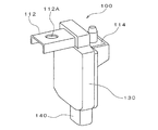
図1は、一実施形態の電流検出装置の構成を示す断面図であり、バッテリに取り付けた状態が示されている。また、図2は電流検出装置の側面図、図3は電流検出装置の斜視図である。 FIG. 1 is a cross-sectional view illustrating a configuration of a current detection device according to an embodiment, showing a state where the current detection device is attached to a battery. 2 is a side view of the current detection device, and FIG. 3 is a perspective view of the current detection device.
これらの図に示すように、本実施形態の電流検出装置100は、導電性材料を用いて形成される抵抗体(シャント抵抗)としてのバスバー110と、バスバー110の通電方向に沿った2箇所の電位差に基づいてバスバー110を流れる電流を検出する電流検出回路が搭載された回路基板120と、バスバー110と回路基板120を収納するケース130と、回路基板120との間で電気的な接続が行われる複数のコネクタターミナル142が内部に露出したコネクタ140と、回路基板120が収納されるケース130の凹部の開口をふさぐ蓋150とを備えている。
As shown in these drawings, the
バスバー110は、ケース130内で折り返された形状を有しており、一方の端部がバッテリ200側の配線に固定されて電気的な接続が行われる第1の固定部112を形成し、他方の端部がハーネスが固定されて電気的な接続が行われる第2の固定部114を形成している。
The
図4は、バスバー110の拡大図である。図4(A)には正面図が、図4(B)には側面図が示されている。図4に示すように、バスバー110は、第1の固定部112に接続された第1の抵抗部110Cと、第2の固定部114に接続された第2の抵抗部110Dと、第1の抵抗部110Cと第2の抵抗部110Dとを折り返して接続するターン部110Eとを有している。また、バスバー110は、第1の抵抗部110Cと第2の抵抗部110Dとが対向しており、通電方向の断面がU字形状となっている。
FIG. 4 is an enlarged view of the
本実施形態では、バッテリ200の側面(電流検出装置100が取り付けられるバッテリ200の端子202に最も近い側面)近傍に概略的には直方体形状を有するケース130が縦長になるように配置されており、この縦長のケース130を挟んで両側に水平方向に第1および第2の固定部112、114が突出している。
In the present embodiment, a
第1の固定部112は、横断面がコの字型形状を有しており、コの字型の底面の一部に貫通穴112A(図3参照)が形成されている。一方、図1に示すように、バッテリ200のマイナス側端子202には、電流検出装置100を取り付けるとともにマイナス側端子202と第1の固定部112との間の配線を兼ねる取付金具210が取り付けられている。この取付金具210の端部には、上向きにボルト211が突出している。本実施形態では、コの字型形状を有する第1の固定部112の凹部開口側から貫通穴112Aに、取付金具210のボルト211を挿入して固定部112をナット(図示せず)で締め付けることにより、取付金具210への第1の固定部112の固定が行われる。なお、この場合には第1の固定部112において取付金具210を取り付ける凹部底面(下面)が取付面(第1の取付面)112Bとなる(図2参照)。
The
また、第2の固定部114は、端部近傍に貫通穴が設けられており、この貫通穴にボルト115が挿入されている。一方、この第2の固定部114に電気的に接続されるハーネス300の端部には貫通穴を有する端子302が設けられており、この端子302の貫通穴に第2の固定部114に設けられたボルト115を挿入して端子302をナット(図示せず)で締め付けることにより、第2の固定部114への端子302の固定が行われる。なお、この場合には第2の固定部114において端子302を取り付ける上面が取付面(第2の取付面)114Bとなる(図2参照)。
The
また、本実施形態では、ケース130は絶縁性および熱伝導性が良好な樹脂材料、例えばPPS(ポリフェニレンサルファイド)樹脂によって形成されており、第1の固定部112あるいは第2の固定部114として外部に露出する部分を除くバスバー110の大部分がこの樹脂材料によってインサート成形されている。
In the present embodiment, the
U字形状を有するバスバー110からは、U字形状の折り返し部分を挟んで離間して配置される2箇所から電位差検出端子110A、110Bが回路基板120側に延びている。これら2つの電位差検出端子110A、110Bは、導電性材料(金属材料)の板材をプレス成形してバスバー110を形成する際に同時に形成され、その後、この板材をU字形状に折り曲げる際に、あるいは折り曲げた後に、回路基板120側に向けて折り曲げられる。バスバー110から延びる2本の電位差検出端子110A、110Bは、回路基板120内の電流検出回路に接続されている。
From the
図5は、電流検出装置100の回路の具体例とバッテリ200等との接続例を示す図である。図5に示すように、電流検出装置100の回路基板120には、バスバー110の一部によって形成されるシャント抵抗100’の両端に接続された差動増幅器10、バッテリ200のプラス端子とマイナス端子に接続された差動増幅器12、温度検出部20、電流検出処理部30、電圧検出処理部32、温度検出処理部34、バッテリ状態検知部36、充電制御部40、通信入出力部(通信I/O)50、52、CANプロトコルにしたがったデータの送受信を行うCANインタフェース(CAN I/F)60、LINプロトコルにしたがったデータの送受信を行うLINインタフェース(LIN I/F)62とが備わっている。一方の差動増幅器10は、シャント抵抗100’の両端電圧を増幅し、電流検出処理部30は、この差動増幅器10の出力電圧に基いてシャント抵抗100’に流れる電流を検出する。差動増幅器10と電流検出処理部30によって電流検出回路が構成されている。他方の差動増幅器12は、バッテリ200の両端電圧(バッテリ電圧)を適正レベルに変換し、電圧検出処理部32は、この差動増幅器12の出力電圧に基いてバッテリ電圧を検出する。温度検出部20は、抵抗とサーミスタによる分圧回路によって構成されており、温度に応じてサーミスタの抵抗値が変化して分圧回路の分圧電圧が変化する。温度検出処理部34は、温度検出部20の出力電圧(分圧電圧)に基いて電流検出装置100の温度(バッテリ200の温度)を検出する。バッテリ状態検知部36は、電流検出処理部30、電圧検出処理部32、温度検出処理部34の各検出値を取り込んでバッテリ状態信号を生成する。電流検出処理部30、電圧検出処理部32、温度検出処理部34、バッテリ状態検知部36によって状態検知センサ38が構成されている。充電制御部40は、バッテリ状態検知部36によって生成されたバッテリ状態信号に基いて車両用発電機(G)80の発電状態を制御する。この発電制御は、通信入出力部52、LINインタフェース62を介して、車両用発電機80に搭載された発電制御装置82に指示を送ることにより行われる。また、バッテリ状態検知部36によって生成されたバッテリ状態信号は、通信入出力部50、CANインタフェース60を介して車両システム70に送られる。車両システム70は、受信したバッテリ状態信号等に基づいてエンジンや各種電気負荷に対する統合的な制御を行う。
FIG. 5 is a diagram illustrating a specific example of a circuit of the
このように、本実施形態の電流検出装置100では、折り返したバスバー110を用い、第1の固定部112と第2の固定部114の間隔を接近させることで搭載性および耐振動性を向上させることができる。また、一般には空気よりも樹脂材料の方が熱伝導性が良好なため、バスバー110を樹脂材料によってインサート成形することにより、バスバー110に通電した際の熱を樹脂材料に効率的に伝達することができ、温度上昇低減に伴う電流検出精度の向上が可能となる。
As described above, in the
また、ケース130を形成する樹脂材料は、絶縁性および熱伝導性が良好な材料、例えばPPS樹脂が用いられているため安定的にバスバー110から樹脂材料に熱を伝達することができる。また、エンジンルーム内に搭載した場合の温度や被液に対する耐久性能を向上させることができる。
In addition, since the resin material forming the
また、バスバー110は、U字形状の折り返し部分と、電流検出回路によって電位差が検出される2箇所の部位(電位差検出端子110A、110Bが引き出される部位)とを含む範囲が樹脂材料の内部に埋設しており、電流検出に関係する部分全体を樹脂材料で覆うことにより、さらに安定的に電流検出精度を向上させることができる。
In addition, the
なお、本発明は上記実施形態に限定されるものではなく、本発明の要旨の範囲内において種々の変形実施が可能である。例えば、上述した実施形態では、バッテリ200のマイナス側の端子202に電流検出装置を接続したが、プラス側の端子に電流検出装置100を接続するようにしてもよい。
In addition, this invention is not limited to the said embodiment, A various deformation | transformation implementation is possible within the range of the summary of this invention. For example, in the embodiment described above, the current detection device is connected to the
また、上述した実施形態では、第1の固定部112あるいは第2の固定部114として外部に露出する部分を除くバスバー110の大部分がケース130内にインサート成形されていたが、バスバー110の一部をケース130内部あるいは外部に露出させてバスバー110の樹脂材料に埋設された範囲を狭くするようにしてもよい。
In the embodiment described above, most of the
また、上述した実施形態では、回路基板120が収納されるケース130の凹部の開口を蓋150によってふさぐようにしたが、回路基板120を含む凹部全体を、エポキシ樹脂等の充填剤を充填して覆うようにしてもよい。
In the above-described embodiment, the opening of the concave portion of the
また、上述した実施形態では、バスバー110と一体に形成された抵抗体(シャント抵抗)を用いたが、少なくとも電位差を検出する2箇所が含まれる範囲をバスバー110とは別体の抵抗体に置き換えるようにしてもよい。
In the above-described embodiment, the resistor (shunt resistor) formed integrally with the
また、上述した実施形態では、第1の固定部112は、横断面がコの字型形状を有しているが、くの字型形状を有していてもよい。あるいは、振動の少ない車両に搭載する場合には、第1の固定部112の横断面を平板形状としてもよい。
In the embodiment described above, the
また、上述した実施形態では、図4に示したように、バスバー110に含まれる第1の抵抗部110Cと第2の抵抗部110Dとを対向させたが、対向する位置からずらすようにしてもよい。
In the above-described embodiment, as shown in FIG. 4, the
図6は、バスバー110の変形例を示す拡大図であり、図4に対応するバスバーの形状が示されている。図6(A)には正面図が、図6(B)には側面図が示されている。図6に示すバスバー110は、第1の抵抗部110C、第2の抵抗部110D、ターン部110Eを有する点は、図4に示したバスバーの形状と同じであるが、第1の抵抗部110Cと第2の抵抗部110Dが対向してはおらず、互いにずれた位置に配置されている。このようなバスバー110を用いた場合であっても、第1の固定部112と第2の固定部114の間隔を接近させることができる点に変わりはないため、搭載性および耐振動性を向上させることができる。
FIG. 6 is an enlarged view showing a modified example of the
また、上述した実施形態では、バスバー110に含まれる第1の抵抗部110Cと第2の抵抗部110Dを平板形状としたが、第1の抵抗部110Cと第2の抵抗部110Dの少なくとも一方を、通電方向に沿った波形形成としてもよい。
In the above-described embodiment, the
図7は、変形例のバスバー110の波形形状部分を示す電流検出装置の部分拡大断面図である。図7に示す例では、バスバー110において、第2の固定部114に接続された第2の抵抗部110Dのみが波形形状に形成されている。第1の抵抗部110Cと第2と第2の抵抗部110Dの少なくとも一方を波形形状とすることにより、インサート成形されたバスバー110と樹脂(ケース130)との密着面積が増えるので、バスバー110に通電した際の熱を樹脂材料にさらに伝達することができるとともに、バスバー110の長さを長くすることによる電流検出精度のさらなる向上が可能となる。また、密着面積の増加により、全体の剛性を高め、よって耐振動性を向上させることもできる。
FIG. 7 is a partial enlarged cross-sectional view of the current detection device showing the waveform-shaped part of the
また、図7に示すように、第1の抵抗部110Cと第2の抵抗部110Dのうち、第2の抵抗部110Dのみに波形を形成するようにしてもよい。ハーネス300が固定されて電気的な接続が行われる第2の固定部114側は、バッテリ200側の配線に固定されて電気的な接続が行われる第1の固定部112よりも大きな振動にさらされるので、第2の抵抗部110Dのみに波形を形成し、第2の固定部114側に続く第2の抵抗部110Dの剛性を向上させることによって、効率的に耐振動性を向上させることができる。なお、第1の抵抗部110Cと第2の抵抗部110Dの両方に、波形を形成すれば、上記効果をさらに高めることができるのは言うまでもない。また、第1の抵抗部110Cのみに波形を形成するようにしてもよい。
Moreover, as shown in FIG. 7, you may make it form a waveform only in
また、上述した実施形態では、電流検出装置100のケース130がバッテリ200の側面に配置される場合について説明したが、図8に示すように、ケース130をバッテリ200の上面200Aに配置し、バスバー110に含まれる第1の抵抗部110Cと第2の抵抗部110Dが、ともにバッテリ200の上面200Aと平行になるようにしてもよい。バッテリ200の側面方向に比べて開放空間の多い上方空間を利用し、しかもバスバー110の折り返しによって天方向の寸法を低減することができるので、さらに搭載性を向上させることができる。
In the above-described embodiment, the case where the
上述したように、本発明によれば、第1の固定部112と第2の固定部114の間隔を接近させることで搭載性および耐振動性を向上させることができる。また、バスバー110を樹脂材料によってインサート成形することにより、バスバー110に通電した際の熱を樹脂材料に効率的に伝達することができ、温度上昇低減に伴う電流検出精度の向上が可能となる。
As described above, according to the present invention, the mountability and vibration resistance can be improved by making the distance between the
100 電流検出装置
110 バスバー
110A、110B 電位差検出端子
110C 第1の抵抗部
110D 第2の抵抗部
110E ターン部
112 第1の固定部
112A 貫通穴
112B 第1の取付面
114 第2の固定部
114B 第2の取付面
115、211 ボルト
120 回路基板
130 ケース
140 コネクタ
142 コネクタターミナル
150 蓋
200 バッテリ
202、302 端子
210 取付金具
300 ハーネス
DESCRIPTION OF
Claims (8)
前記バッテリ側の配線に固定されて電気的な接続が行われる第1の固定部と、
前記ハーネスが固定されて電気的な接続が行われる第2の固定部と、
前記第1および第2の固定部との間に挿入された抵抗体と、
前記抵抗体の通電方向に沿った2箇所の電位差に基づいて前記抵抗体を流れる電流を検出する電流検出回路が搭載される回路基板と、
前記第1および第2の固定部の間に配置され、前記抵抗体と前記回路基板とが収納されるケースと、
を備え、前記抵抗体は、前記第1の固定部に接続された第1の抵抗部と、前記第2の固定部に接続された第2の抵抗部と、前記第1の抵抗部と前記第2の抵抗部とを折り返して接続するターン部とを有し、前記抵抗体の少なくとも一部が前記ケースを形成する樹脂材料によってインサート成形されていることを特徴とする電流検出装置。 A current detection device for detecting a current flowing through a harness through a terminal of a battery,
A first fixing portion fixed to the wiring on the battery side and electrically connected;
A second fixing portion in which the harness is fixed and electrical connection is made;
A resistor inserted between the first and second fixing portions;
A circuit board on which a current detection circuit for detecting a current flowing through the resistor based on a potential difference between two locations along the energization direction of the resistor is mounted;
A case that is disposed between the first and second fixing portions and that accommodates the resistor and the circuit board;
The resistor includes: a first resistor connected to the first fixed part; a second resistor connected to the second fixed part; the first resistor; A current detection device comprising: a turn portion that folds and connects the second resistance portion; and at least a part of the resistor is insert-molded with a resin material that forms the case.
前記抵抗体は、前記第1の抵抗部と前記第2の抵抗部とが対向しており、前記通電方向の断面がU字形状であることを特徴とする電流検出装置。 In claim 1,
The current detection device according to claim 1, wherein the first resistance portion and the second resistance portion are opposed to each other, and a cross section in the energization direction is U-shaped.
前記第1の抵抗部と前記第2の抵抗部の少なくとも一方が、前記通電方向に沿った波形を形成していることを特徴とする電流検出装置。 In claim 1 or 2,
At least one of said 1st resistance part and said 2nd resistance part forms the waveform along the said electricity supply direction, The electric current detection apparatus characterized by the above-mentioned.
前記第2の抵抗部のみに前記波形が形成されていることを特徴とする電流検出装置。 In claim 3,
The current detection device, wherein the waveform is formed only in the second resistance portion.
前記樹脂材料は、絶縁性および熱伝導性が良好な材料であることを特徴とする電流検出装置。 In any one of Claims 1-4,
The current detection apparatus, wherein the resin material is a material having good insulation and thermal conductivity.
前記樹脂材料は、PPS樹脂であることを特徴とする電流検出装置。 In any one of Claims 1-5,
The current detection apparatus, wherein the resin material is a PPS resin.
前記電流検出回路は、U字形状の折り返し部分を挟んで互いに離間して配置される2箇所の部位の電位差を検出しており、
前記抵抗体は、U字形状の折り返し部分と、前記電流検出回路によって電位差が検出される2箇所の部位とを含む範囲が少なくとも前記樹脂材料の内部に埋設していることを特徴とする電流検出装置。 In any one of Claims 1-6,
The current detection circuit detects a potential difference between two portions that are spaced apart from each other across a U-shaped folded portion,
The resistor has a range including at least a U-shaped folded portion and two portions where a potential difference is detected by the current detection circuit embedded in at least the inside of the resin material. apparatus.
前記第1および第2の抵抗体のそれぞれは、前記バッテリの上面に平行に配置されていることを特徴とする電流検出装置。 In any one of Claims 1-7,
Each of the said 1st and 2nd resistor is arrange | positioned in parallel with the upper surface of the said battery, The electric current detection apparatus characterized by the above-mentioned.
Priority Applications (3)
| Application Number | Priority Date | Filing Date | Title |
|---|---|---|---|
| JP2010110708A JP4877404B2 (en) | 2009-08-31 | 2010-05-13 | Current detector |
| US12/869,174 US8680878B2 (en) | 2009-08-31 | 2010-08-26 | Electric current measuring device with improved installability |
| DE102010037235A DE102010037235A1 (en) | 2009-08-31 | 2010-08-30 | Electric current measuring device with improved installation |
Applications Claiming Priority (3)
| Application Number | Priority Date | Filing Date | Title |
|---|---|---|---|
| JP2009200022 | 2009-08-31 | ||
| JP2009200022 | 2009-08-31 | ||
| JP2010110708A JP4877404B2 (en) | 2009-08-31 | 2010-05-13 | Current detector |
Publications (2)
| Publication Number | Publication Date |
|---|---|
| JP2011069807A true JP2011069807A (en) | 2011-04-07 |
| JP4877404B2 JP4877404B2 (en) | 2012-02-15 |
Family
ID=43536344
Family Applications (1)
| Application Number | Title | Priority Date | Filing Date |
|---|---|---|---|
| JP2010110708A Active JP4877404B2 (en) | 2009-08-31 | 2010-05-13 | Current detector |
Country Status (3)
| Country | Link |
|---|---|
| US (1) | US8680878B2 (en) |
| JP (1) | JP4877404B2 (en) |
| DE (1) | DE102010037235A1 (en) |
Cited By (7)
| Publication number | Priority date | Publication date | Assignee | Title |
|---|---|---|---|---|
| JP2013096881A (en) * | 2011-11-02 | 2013-05-20 | Denso Corp | Current detector |
| JP2013096856A (en) * | 2011-11-01 | 2013-05-20 | Denso Corp | Current detector |
| JP2015025694A (en) * | 2013-07-25 | 2015-02-05 | 矢崎総業株式会社 | Shunt resistor current sensor |
| JP2016180765A (en) * | 2016-07-12 | 2016-10-13 | Koa株式会社 | Shunt resistance type current detection device |
| JP2016537637A (en) * | 2013-11-26 | 2016-12-01 | スマート エレクトロニクス インク | Current measuring element and current measuring element assembly |
| JP2017505899A (en) * | 2013-11-26 | 2017-02-23 | スマート エレクトロニクス インク | CURRENT MEASURING ELEMENT AND METHOD FOR MANUFACTURING CURRENT MEASURING ELEMENT ASSEMBLY |
| EP3683804A4 (en) * | 2017-09-11 | 2021-05-26 | Melquisedec Francisquini | Structural arrangement for use in a conducting busbar |
Families Citing this family (13)
| Publication number | Priority date | Publication date | Assignee | Title |
|---|---|---|---|---|
| DE102011083307A1 (en) * | 2011-09-23 | 2013-03-28 | Continental Automotive Gmbh | Device for measuring a battery current |
| US9739819B2 (en) * | 2013-12-20 | 2017-08-22 | Ford Global Technologies, Llc | Cable joint integrity detection systems and methods |
| DE102014011593B4 (en) * | 2014-08-01 | 2016-05-04 | Isabellenhütte Heusler Gmbh & Co. Kg | Resistance, in particular low-impedance current measuring resistor |
| DE102014218708A1 (en) * | 2014-09-17 | 2016-03-17 | Continental Teves Ag & Co. Ohg | Shunt current measurement with temperature compensation |
| CN104407299A (en) * | 2014-11-20 | 2015-03-11 | 合肥国轩高科动力能源股份公司 | Internal resistance voltage testing machine for battery |
| CN209204686U (en) * | 2015-05-22 | 2019-08-06 | 大陆汽车有限公司 | Current sensor apparatus |
| EP3115798A1 (en) * | 2015-07-10 | 2017-01-11 | Continental Automotive GmbH | Battery sensor unit with resistance element |
| KR102018719B1 (en) * | 2016-02-12 | 2019-09-04 | 주식회사 엘지화학 | Busbar for cooling battery cell and battery module using thereof |
| US10782322B2 (en) * | 2016-05-04 | 2020-09-22 | Safran Electrical & Power | Busbar current sensor assembly |
| DE102016010012B4 (en) * | 2016-08-17 | 2018-06-21 | Isabellenhütte Heusler Gmbh & Co. Kg | Measuring arrangement for measuring an electric current in the high current range |
| US20190081362A1 (en) * | 2017-09-08 | 2019-03-14 | Apple Inc. | Over-Molded Printed Circuit Board Connector |
| JP7102456B2 (en) * | 2020-04-13 | 2022-07-19 | 矢崎総業株式会社 | Current sensor |
| DE102021204479A1 (en) | 2021-05-04 | 2022-06-30 | Vitesco Technologies Germany Gmbh | Circuit arrangement for measuring the current strength of a current, battery device |
Citations (5)
| Publication number | Priority date | Publication date | Assignee | Title |
|---|---|---|---|---|
| JPS63124701A (en) * | 1986-11-14 | 1988-05-28 | Mitsubishi Electric Corp | Air conditioner for vehicle |
| JPH032675A (en) * | 1989-05-31 | 1991-01-09 | Hitachi Ltd | Discharge/charge current sensor of battery for automobile |
| JPH0483175A (en) * | 1990-07-25 | 1992-03-17 | Mitsubishi Electric Corp | Current detector |
| JP2000068101A (en) * | 1998-08-18 | 2000-03-03 | Matsushita Electric Ind Co Ltd | Resistor and method of producing the same |
| JP2002319501A (en) * | 2001-01-15 | 2002-10-31 | Matsushita Electric Works Ltd | Shunt resistor and method for adjusting its resistance |
Family Cites Families (6)
| Publication number | Priority date | Publication date | Assignee | Title |
|---|---|---|---|---|
| FR2879751B1 (en) * | 2004-12-20 | 2007-02-23 | Johnson Controls Tech Co | DEVICE FOR MEASURING CIRCULATING CURRENT IN A CABLE |
| JP2008039571A (en) | 2006-08-04 | 2008-02-21 | Denso Corp | Current sensor |
| US7381101B2 (en) * | 2006-08-25 | 2008-06-03 | Lear Corporation | Battery post connector |
| US7663376B2 (en) * | 2007-08-06 | 2010-02-16 | Lear Corporation | Printed circuit board for sensing voltage drop |
| JP2009200022A (en) | 2008-02-21 | 2009-09-03 | Denshi System Design Kk | Primary/secondary common battery storage device |
| JP2010110708A (en) | 2008-11-07 | 2010-05-20 | Komatsu Seiren Co Ltd | Wiping tool |
-
2010
- 2010-05-13 JP JP2010110708A patent/JP4877404B2/en active Active
- 2010-08-26 US US12/869,174 patent/US8680878B2/en active Active
- 2010-08-30 DE DE102010037235A patent/DE102010037235A1/en active Pending
Patent Citations (5)
| Publication number | Priority date | Publication date | Assignee | Title |
|---|---|---|---|---|
| JPS63124701A (en) * | 1986-11-14 | 1988-05-28 | Mitsubishi Electric Corp | Air conditioner for vehicle |
| JPH032675A (en) * | 1989-05-31 | 1991-01-09 | Hitachi Ltd | Discharge/charge current sensor of battery for automobile |
| JPH0483175A (en) * | 1990-07-25 | 1992-03-17 | Mitsubishi Electric Corp | Current detector |
| JP2000068101A (en) * | 1998-08-18 | 2000-03-03 | Matsushita Electric Ind Co Ltd | Resistor and method of producing the same |
| JP2002319501A (en) * | 2001-01-15 | 2002-10-31 | Matsushita Electric Works Ltd | Shunt resistor and method for adjusting its resistance |
Cited By (8)
| Publication number | Priority date | Publication date | Assignee | Title |
|---|---|---|---|---|
| JP2013096856A (en) * | 2011-11-01 | 2013-05-20 | Denso Corp | Current detector |
| JP2013096881A (en) * | 2011-11-02 | 2013-05-20 | Denso Corp | Current detector |
| JP2015025694A (en) * | 2013-07-25 | 2015-02-05 | 矢崎総業株式会社 | Shunt resistor current sensor |
| US9784767B2 (en) | 2013-07-25 | 2017-10-10 | Yazaki Corporation | Shunt resistance type current sensor |
| JP2016537637A (en) * | 2013-11-26 | 2016-12-01 | スマート エレクトロニクス インク | Current measuring element and current measuring element assembly |
| JP2017505899A (en) * | 2013-11-26 | 2017-02-23 | スマート エレクトロニクス インク | CURRENT MEASURING ELEMENT AND METHOD FOR MANUFACTURING CURRENT MEASURING ELEMENT ASSEMBLY |
| JP2016180765A (en) * | 2016-07-12 | 2016-10-13 | Koa株式会社 | Shunt resistance type current detection device |
| EP3683804A4 (en) * | 2017-09-11 | 2021-05-26 | Melquisedec Francisquini | Structural arrangement for use in a conducting busbar |
Also Published As
| Publication number | Publication date |
|---|---|
| JP4877404B2 (en) | 2012-02-15 |
| US8680878B2 (en) | 2014-03-25 |
| DE102010037235A1 (en) | 2011-03-10 |
| US20110050260A1 (en) | 2011-03-03 |
Similar Documents
| Publication | Publication Date | Title |
|---|---|---|
| JP4877404B2 (en) | Current detector | |
| JP5617278B2 (en) | Current detector | |
| JP5630691B2 (en) | Current detector | |
| US20150369877A1 (en) | Integrally formed current sensor device | |
| JP2014203893A (en) | Capacitor module | |
| JP2011053003A (en) | Current detector | |
| JP5709056B2 (en) | Current detector | |
| EP2179461A2 (en) | Storage battery arrangement | |
| JP4818218B2 (en) | Power supply for vehicle | |
| JP2013096782A (en) | Current detector | |
| JP2014173437A (en) | Blowby gas heater | |
| JP5435442B2 (en) | Battery state detection sensor device | |
| JP5859814B2 (en) | Current detector | |
| US10424947B2 (en) | Battery monitoring device | |
| JP2009146574A (en) | Battery sensor module | |
| US20230028663A1 (en) | Electrical connection box | |
| JP2011117853A (en) | Current detector | |
| JP5183775B2 (en) | Power supply for vehicle | |
| JP6011460B2 (en) | Electronic equipment | |
| JP2005188931A (en) | Voltage-drop type current measuring device | |
| JP5018846B2 (en) | Current detector | |
| JP2018159613A (en) | Temperature detector | |
| JP4614674B2 (en) | Battery tray device | |
| JP5693853B2 (en) | Current detector | |
| JP2005188972A (en) | Voltage-drop type current measuring device |
Legal Events
| Date | Code | Title | Description |
|---|---|---|---|
| A131 | Notification of reasons for refusal |
Free format text: JAPANESE INTERMEDIATE CODE: A131 Effective date: 20110802 |
|
| A521 | Request for written amendment filed |
Free format text: JAPANESE INTERMEDIATE CODE: A523 Effective date: 20110919 |
|
| TRDD | Decision of grant or rejection written | ||
| A01 | Written decision to grant a patent or to grant a registration (utility model) |
Free format text: JAPANESE INTERMEDIATE CODE: A01 Effective date: 20111101 |
|
| A01 | Written decision to grant a patent or to grant a registration (utility model) |
Free format text: JAPANESE INTERMEDIATE CODE: A01 |
|
| A61 | First payment of annual fees (during grant procedure) |
Free format text: JAPANESE INTERMEDIATE CODE: A61 Effective date: 20111114 |
|
| R151 | Written notification of patent or utility model registration |
Ref document number: 4877404 Country of ref document: JP Free format text: JAPANESE INTERMEDIATE CODE: R151 |
|
| FPAY | Renewal fee payment (event date is renewal date of database) |
Free format text: PAYMENT UNTIL: 20141209 Year of fee payment: 3 |
|
| R250 | Receipt of annual fees |
Free format text: JAPANESE INTERMEDIATE CODE: R250 |
|
| R250 | Receipt of annual fees |
Free format text: JAPANESE INTERMEDIATE CODE: R250 |
|
| R250 | Receipt of annual fees |
Free format text: JAPANESE INTERMEDIATE CODE: R250 |
|
| R250 | Receipt of annual fees |
Free format text: JAPANESE INTERMEDIATE CODE: R250 |
|
| R250 | Receipt of annual fees |
Free format text: JAPANESE INTERMEDIATE CODE: R250 |
|
| R250 | Receipt of annual fees |
Free format text: JAPANESE INTERMEDIATE CODE: R250 |
|
| R250 | Receipt of annual fees |
Free format text: JAPANESE INTERMEDIATE CODE: R250 |
|
| R250 | Receipt of annual fees |
Free format text: JAPANESE INTERMEDIATE CODE: R250 |
|
| R250 | Receipt of annual fees |
Free format text: JAPANESE INTERMEDIATE CODE: R250 |