JP2011069771A - Lighting system of resin cap - Google Patents
Lighting system of resin cap Download PDFInfo
- Publication number
- JP2011069771A JP2011069771A JP2009222423A JP2009222423A JP2011069771A JP 2011069771 A JP2011069771 A JP 2011069771A JP 2009222423 A JP2009222423 A JP 2009222423A JP 2009222423 A JP2009222423 A JP 2009222423A JP 2011069771 A JP2011069771 A JP 2011069771A
- Authority
- JP
- Japan
- Prior art keywords
- cap
- illumination
- ring
- type rgb
- rgb illumination
- Prior art date
- Legal status (The legal status is an assumption and is not a legal conclusion. Google has not performed a legal analysis and makes no representation as to the accuracy of the status listed.)
- Pending
Links
- 239000011347 resin Substances 0.000 title claims abstract description 62
- 229920005989 resin Polymers 0.000 title claims abstract description 62
- 238000005286 illumination Methods 0.000 claims abstract description 200
- 238000007689 inspection Methods 0.000 claims abstract description 90
- 238000003384 imaging method Methods 0.000 claims abstract description 51
- 230000002093 peripheral effect Effects 0.000 claims description 3
- 238000000034 method Methods 0.000 description 22
- 238000010586 diagram Methods 0.000 description 21
- 230000002950 deficient Effects 0.000 description 17
- 230000007547 defect Effects 0.000 description 5
- 239000003086 colorant Substances 0.000 description 3
- 238000007599 discharging Methods 0.000 description 3
- 238000003860 storage Methods 0.000 description 3
- 238000004519 manufacturing process Methods 0.000 description 2
- 230000003287 optical effect Effects 0.000 description 2
- 235000014214 soft drink Nutrition 0.000 description 2
- 238000011179 visual inspection Methods 0.000 description 2
- 230000005856 abnormality Effects 0.000 description 1
- 230000015572 biosynthetic process Effects 0.000 description 1
- 238000005520 cutting process Methods 0.000 description 1
- 230000000694 effects Effects 0.000 description 1
- 229910052736 halogen Inorganic materials 0.000 description 1
- 150000002367 halogens Chemical class 0.000 description 1
- 238000000465 moulding Methods 0.000 description 1
Images


Landscapes
- Investigating Materials By The Use Of Optical Means Adapted For Particular Applications (AREA)
Abstract
Description
本発明は、樹脂製キャップの照明装置に係り、特に、樹脂製キャップを撮像により外観を検査する際に樹脂製キャップを照明するための照明装置に関するものである。 The present invention relates to a lighting device for a resin cap, and more particularly to a lighting device for illuminating a resin cap when the appearance of the resin cap is inspected by imaging.
従来から、清涼飲料などを充填するために軽量のプラスチックボトルであるペットボトル(PETボトル)が多用されている。ペットボトルの口部は樹脂製キャップにより密封されている。樹脂製キャップは樹脂成形により製作され、この樹脂製キャップは白色に限らず、青色、赤色等の様々な色が用いられている。またキャップには文字や模様が印刷されている。そのため、樹脂製キャップは、製作後に変形の有無、印刷時等に生じた汚れの有無、異物付着の有無、ウィング部の異常(ショートウィングと呼ばれる)の有無、キャップ側面の一部の欠落(ブリッジ切れと呼ばれる)等の外観検査を行う必要がある。 Conventionally, PET bottles (PET bottles), which are lightweight plastic bottles, are frequently used for filling soft drinks and the like. The mouth of the plastic bottle is sealed with a resin cap. The resin cap is manufactured by resin molding, and the resin cap is not limited to white, and various colors such as blue and red are used. In addition, characters and patterns are printed on the cap. For this reason, the resin cap is not deformed after production, whether or not dirt has occurred during printing, whether or not foreign matter is attached, whether or not there is an abnormality in the wing (called a short wing), and missing parts on the side of the cap (bridge) It is necessary to perform an appearance inspection such as cutting.
従来から、ペットボトル等の容器を撮像して外観検査を行う容器検査装置が知られている。この容器検査装置においては、メインロータにより容器を保持して所定の円形軌道に沿って公転させつつ容器を自転させ、容器の搬送系路に沿って配置された照明装置と撮像装置によって容器の外観を撮像して検査を行っている。 2. Description of the Related Art Conventionally, a container inspection apparatus that performs an appearance inspection by imaging a container such as a plastic bottle is known. In this container inspection apparatus, the container is rotated by holding the container by the main rotor and revolving along a predetermined circular orbit, and the outer appearance of the container by the illumination device and the image pickup device arranged along the conveyance system path of the container The image is taken for inspection.
しかしながら、上記容器検査装置と同様のメインロータを用いてキャップの外観検査を実施しようとすると、メインロータはロータリ機構によって連続的に回転(公転)しているため、キャップを停止させて撮像する必要がある一部の検査については行うことができないという問題点がある。 However, if the appearance inspection of the cap is performed using the same main rotor as the container inspection apparatus, the main rotor is continuously rotated (revolved) by the rotary mechanism, so it is necessary to stop the cap and take an image. There is a problem that some inspections cannot be performed.
すなわち、清涼飲料などに用いられるキャップには開栓されたことが分かる機構が設けられており、キャップはねじのあるキャップの本体とその下側にあるリングで構成されている。キャップ本体とリングはいくつかの細いつなぎ目(ブリッジと呼ばれる)でつながり、キャップを初めて開けたときにこのブリッジが切れ、本体とリングが離れることでキャップが開けられたことが分かる。キャップの製造時に前記ブリッジがつながっていないで切れている場合があるため、外観検査によりこのブリッジ切れを検出する必要がある。ブリッジ切れは、キャップを検査位置で公転を停止させ、かつキャップを自転させつつ撮像することにより検出可能であるため、連続的に回転するロータリ型のメインロータを用いて検査を行うことができない。 That is, a cap used for a soft drink or the like is provided with a mechanism indicating that the cap has been opened, and the cap is composed of a cap body with a screw and a ring on the lower side thereof. It can be seen that the cap body and the ring are connected by several thin seams (called bridges), and when the cap is opened for the first time, this bridge is broken and the cap is opened by separating the body and the ring. Since there is a case where the bridge is disconnected without being connected at the time of manufacturing the cap, it is necessary to detect this bridge disconnection by visual inspection. Bridge breakage can be detected by stopping the revolution of the cap at the inspection position and imaging while rotating the cap, so that the inspection cannot be performed using the rotary main rotor that rotates continuously.
そのため、本発明者らは、キャップを保持して所定の円形軌道に沿って間欠的に搬送するロータリインデックス搬送方式(回転割出搬送方式)の適用を試みたものである。しかしながら、このロータリインデックス搬送方式(回転割出搬送方式)は、キャップを支持する多数の支持台を円形軌道に沿って間欠的に搬送するため、すなわち多数の支持台を円形軌道に沿って搬送して検査位置で停止させ、検査後に多数の支持台を再び円形軌道に沿って搬送するという発進と停止を繰り返すため、慣性力が大きく、高速搬送ができないため、検査処理数量を増加することができないという問題点がある。 For this reason, the present inventors have tried to apply a rotary index conveying method (rotational index conveying method) in which a cap is held and conveyed intermittently along a predetermined circular orbit. However, this rotary index conveyance method (rotational index conveyance method) is used to intermittently convey a large number of support bases that support the cap along a circular path, that is, to transport a large number of support bases along the circular path. The inspection process is stopped at the inspection position, and after the inspection, a large number of support bases are transferred again and again along the circular path, so the inertial force is large and high-speed conveyance is impossible, so the number of inspection processes cannot be increased. There is a problem.
そこで、本発明者らは、ロータリインデックス搬送方式(回転割出搬送方式)を採用するため高速搬送が困難である状況にも拘らず、検査処理数量を増加することができるシステムについて鋭意研究を行った結果、キャップを支持して自転させる支持台の数を2倍にし、かつ2台の支持台を対(ペア)として間欠搬送する方式を見出したものである。ところが、このように支持台の数を2倍にした場合に、対(ペア)をなす2台の支持台を近接した位置に配置しなければならない。この場合、キャップ外側面の汚れや異物付着の有無等を検査するキャップ外側面の外観検査を行う際、キャップ1つに対し1つのリング型照明を設ければ、キャップ外側面を均一に照明することができるが、2つのキャップは接近していてリング型照明を2つ設けることが困難であった。そのため、2つのキャップに対し、1つのリング型照明を設けたが、キャップ外側面に均一に照明することができず、照明ムラが生じるという問題点がある。 Therefore, the present inventors have conducted intensive research on a system that can increase the number of inspection processes despite the fact that high-speed conveyance is difficult because the rotary index conveyance system (rotational index conveyance system) is adopted. As a result, the present inventors have found a method in which the number of support bases that support and rotate the cap is doubled, and the two support bases are intermittently conveyed as a pair. However, when the number of support bases is doubled as described above, the two support bases forming a pair must be arranged at close positions. In this case, when performing an appearance inspection of the outer surface of the cap for inspecting the outer surface of the cap for dirt or foreign matter, if one ring-type illumination is provided for each cap, the outer surface of the cap is illuminated uniformly. However, the two caps were close and it was difficult to provide two ring lights. For this reason, one ring-type illumination is provided for the two caps, but there is a problem in that the outer surface of the cap cannot be illuminated uniformly and uneven illumination occurs.
本発明は、上述の事情に鑑みなされたもので、ロータリインデックス搬送方式(回転割出搬送方式)を採用するため高速搬送が困難である状況にも拘らず、検査処理数量を増やすことができ、かつ対をなす2台の支持台上のキャップのカメラ側の外側面を照明ムラなく均一に照明することができる樹脂製キャップの照明装置を提供することを目的とする。 The present invention has been made in view of the above-described circumstances, and can employ a rotary index conveyance method (rotational index conveyance method) to increase the number of inspection processes despite the fact that high-speed conveyance is difficult. An object of the present invention is to provide a resin cap illumination device that can uniformly illuminate the camera-side outer surface of the caps on the two support bases that make a pair.
上述の目的を達成するため、本発明の樹脂製キャップの照明装置の第1の態様は、樹脂製キャップを円形軌道に沿って間欠的に搬送し、停止位置にある検査ステーションで樹脂製キャップを側方から撮像する撮像装置により樹脂製キャップを検査する検査機の検査ステーションに設置される照明装置において、対をなす2個の樹脂製キャップの上方に水平に配置されたリング型RGB照明と、前記リング型RGB照明の直下に配置されるとともに、前記リング型RGB照明の略半分を覆うように前記撮像装置から離間した側に配置される第1遮光板と、前記リング型RGB照明の直下に鉛直に配置されるとともに、前記リング型RGB照明の外周縁から中心部に向かって樹脂製キャップの搬送方向と略直交する方向に延びる第2遮光板とを備え、前記リング型RGB照明は、リング型RGB照明の中心が前記対をなす2個のキャップの軸心を結ぶ線分の中点から撮像装置側に偏倚するように配置されていることを特徴とする。 In order to achieve the above-mentioned object, the first aspect of the resin cap lighting device of the present invention is to intermittently convey the resin cap along a circular path and to dispose the resin cap at the inspection station at the stop position. In an illumination device installed in an inspection station of an inspection machine that inspects a resin cap with an imaging device that images from the side, a ring-type RGB illumination disposed horizontally above two paired resin caps; A first light-shielding plate disposed immediately below the ring-type RGB illumination, and disposed on a side away from the imaging device so as to cover substantially half of the ring-type RGB illumination, and directly below the ring-type RGB illumination A second light-shielding plate that is vertically arranged and extends from the outer periphery of the ring-type RGB illumination toward the center of the ring-type RGB illumination in a direction substantially perpendicular to the resin cap conveyance direction. The ring-type RGB illumination is arranged so that the center of the ring-type RGB illumination is biased toward the imaging device from the midpoint of the line segment connecting the axes of the two caps that form the pair. To do.
本発明は、ロータリインデックス搬送方式(回転割出搬送方式)を採用するため高速搬送が困難である状況にも拘らず、検査処理数量を増加するため、キャップを支持して自転させる支持台の数を2倍にし、かつ2台の支持台を対(ペア)として間欠搬送する方式である。ところが、このように支持台の数を2倍にした場合に、対(ペア)をなす2台の支持台を近接した位置に配置しなければならない。この場合、キャップ外側面の汚れや異物付着の有無等を検査するキャップ外側面の外観検査を行う際、キャップ1つに対し1つのリング型照明を設ければ、キャップ外側面を均一に照明することができるが、2つのキャップは接近していてリング型照明を2つ設けることが困難であった。そこで、本発明の照明装置においては、対をなす2個の支持台上の2個のキャップの上方に、リング型RGB照明を配置している。ところが、2つのキャップに対し、1つのリング型照明を設ける場合、キャップ外側面を均一に照明することができず、照明ムラが生じるという問題点がある。 The present invention employs a rotary index transfer method (rotational index transfer method), so that the number of support bases to be rotated while supporting a cap is increased in order to increase the number of inspection processes despite the fact that high-speed transfer is difficult. Is doubled, and the two support tables are intermittently conveyed as a pair. However, when the number of support bases is doubled as described above, the two support bases forming a pair must be arranged at close positions. In this case, when performing an appearance inspection of the outer surface of the cap for inspecting the outer surface of the cap for dirt or foreign matter, if one ring-type illumination is provided for each cap, the outer surface of the cap is illuminated uniformly. However, the two caps were close and it was difficult to provide two ring lights. Therefore, in the illumination device of the present invention, the ring type RGB illumination is arranged above the two caps on the two support bases that make a pair. However, when one ring-type illumination is provided for two caps, there is a problem that the outer surface of the cap cannot be illuminated uniformly, resulting in uneven illumination.
そのため、本発明においては、前記リング型RGB照明は、リング型RGB照明の中心が前記対をなす2個のキャップの軸心を結ぶ線分の中点から撮像装置側に偏倚するように配置されており、円筒状のキャップの外側面のうち最もリング型RGB照明に近接していて光が廻り込み難かった部分に、リング型RGB照明におけるキャップから離間した部分からも光が廻り込むようにし、キャップ外側面の前記照明に近接した部分に当たる光量を増加させ、照明ムラを改善するようにしている。
また、本発明においては、リング型RGB照明は、キャップの撮像装置側の外側面を照明すれば良いので、リング型RGB照明の直下にリング型RGB照明の下面の略半分を覆うように第1遮光板を配置している。
さらに、本発明においては、リング型RGB照明の直下に鉛直に配置されるとともに、リング型RGB照明の外周縁から中心部に向かって樹脂製キャップの搬送方向と略直交する方向に延びる第2遮光板を備えている。この第2遮光板により、リング型RGB照明のうち概略半円状の照明領域を2つに分割することができ、2つのキャップのうち一方のキャップに近い1/4円弧状の照明領域を一方のキャップの照明専用とし、他方のキャップに近い他の1/4円弧状の照明領域を他方のキャップの照明専用とする。これにより、キャップ外側面のうち撮像装置に近い領域には1/4円弧状の照明領域の一方からしか照明されずに、この領域の照明の強度を下げることができ、照明ムラを改善することができる。
Therefore, in the present invention, the ring type RGB illumination is arranged so that the center of the ring type RGB illumination is biased toward the imaging device from the midpoint of the line segment connecting the axes of the two caps that make the pair. In the outer surface of the cylindrical cap, the light that is closest to the ring-type RGB illumination and the light is difficult to go around also from the part that is separated from the cap in the ring-type RGB illumination, The amount of light hitting a portion of the outer surface of the cap close to the illumination is increased to improve illumination unevenness.
Further, in the present invention, the ring type RGB illumination only needs to illuminate the outer surface of the cap on the imaging device side, so the first half of the lower surface of the ring type RGB illumination is covered directly below the ring type RGB illumination. A light shielding plate is arranged.
Further, in the present invention, the second light-shielding light is arranged vertically immediately below the ring-type RGB illumination and extends in a direction substantially perpendicular to the transport direction of the resin cap from the outer peripheral edge of the ring-type RGB illumination toward the center. It has a board. The second light shielding plate can divide a substantially semicircular illumination area of the ring-type RGB illumination into two, and one of the two arcs of a quarter arc-shaped illumination area close to one of the caps. The other cap-shaped illumination area close to the other cap is dedicated to the illumination of the other cap. As a result, the area near the imaging device on the outer surface of the cap is illuminated only from one of the ¼ arc-shaped illumination areas, and the intensity of illumination in this area can be reduced, thereby improving illumination unevenness. Can do.
本発明の好ましい態様は、前記対をなす2個の樹脂製キャップの斜め下方に配置されるとともに、前記撮像装置側に配置され、前記リング型RGB照明から入射した光を前記対をなす2個の樹脂製キャップに向けて反射させる反射板を備えたことを特徴とする。
本発明によれば、円筒状のキャップの外側面のうち最もリング型RGB照明に近接していて光が廻り込み難かった部分に、反射板によってリング型RGB照明からの光を反射して反射光を入射させ、キャップの外側面のうち最もリング型RGB照明に近接している部分の光量を増加させ、照明ムラを改善するようにしている。
According to a preferred aspect of the present invention, the two resin caps that are disposed obliquely below the pair of resin caps and that are disposed on the imaging device side and that make incident light from the ring type RGB illumination form the pair It is characterized by comprising a reflector that reflects toward the resin cap.
According to the present invention, the light from the ring-type RGB illumination is reflected by the reflector on the portion of the outer surface of the cylindrical cap that is closest to the ring-type RGB illumination and the light is difficult to go around. And the amount of light at the portion closest to the ring-type RGB illumination on the outer surface of the cap is increased to improve illumination unevenness.
本発明の好ましい態様は、前記リング型RGB照明は、赤色LED、緑色LED、青色LEDをリング状に配列した照明からなることを特徴とする。
本発明によれば、赤色LED、緑色LED、青色LEDの点灯・消灯を適宜組合せることによって、樹脂製キャップの色に応じて、欠陥が際立つようにコントラストが強調できるような配色に照明を調光できる。
In a preferred aspect of the present invention, the ring-type RGB illumination includes illumination in which red LEDs, green LEDs, and blue LEDs are arranged in a ring shape.
According to the present invention, the lighting is adjusted to a color scheme that can enhance the contrast so that a defect is conspicuous according to the color of the resin cap by appropriately combining turning on / off of the red LED, the green LED, and the blue LED. Can shine.
本発明の好ましい態様は、前記反射板は、対をなす2個の樹脂製キャップの斜め下方に水平に配置された略矩形状の板状体からなり、樹脂製キャップに近接した部分の幅は小さく、樹脂製キャップから離間した部分の幅は大きく設定されていることを特徴とする。
本発明によれば、反射板の幅が小さい部分においてリング型RGB照明からの光を反射して反射光を、反射板に近接したキャップの外側面の下部側に入射させ、反射板の幅が大きい部分においてリング型RGB照明からの光を反射して反射光を、反射板から離間した部分の上下部に入射させる。
In a preferred aspect of the present invention, the reflecting plate is formed of a substantially rectangular plate-like body horizontally disposed diagonally below two paired resin caps, and the width of the portion adjacent to the resin cap is The width of the small part spaced apart from the resin cap is set large.
According to the present invention, the light from the ring-type RGB illumination is reflected at a portion where the width of the reflector is small, and the reflected light is incident on the lower side of the outer surface of the cap adjacent to the reflector, so that the width of the reflector is The light from the ring-type RGB illumination is reflected at a large portion, and the reflected light is incident on the upper and lower portions of the portion separated from the reflector.
本発明の樹脂製キャップの外観検査機の第1の態様は、対をなす2個の樹脂製キャップを支持する2台の支持台を支持する複数の支持ユニットを間欠的に搬送する回転割出装置と、請求項1乃至4のいずれか1項に記載の照明装置と、前記2台の支持台上の対をなす2個の樹脂製キャップに対応して設置された撮像装置とを備えたことを特徴とする。
本発明の好ましい態様は、前記撮像装置は、白黒のCCDカメラからなることを特徴とする。
The first aspect of the resin cap appearance inspection machine according to the present invention is a rotary indexing system that intermittently conveys a plurality of support units that support two support bases that support two resin caps that make a pair. An illumination device according to any one of
In a preferred aspect of the present invention, the imaging device is a monochrome CCD camera.
本発明は、以下に列挙する効果を奏する。
(1)ロータリインデックス搬送方式(回転割出搬送方式)を採用するため高速搬送が困難である状況にも拘らず、キャップを支持して停止位置でキャップを自転させる支持台の数を2倍にし、かつ2台の支持台を対(ペア)として間欠搬送する方式を採用したため、単位時間あたりのキャップの検査処理数量を飛躍的に増加することができる。
(2)キャップを支持して自転させる支持台の数を2倍にした場合に、対(ペア)をなす2台の支持台を近接した位置に配置しなければならないが、キャップ外側面の汚れや異物付着の有無等を検査するキャップ外側面の外観検査を行うために、対をなす2つのキャップに対して1つのリング型照明を設け、遮光板等を適所に配置することにより、キャップ外側面の照明ムラをなくし、キャップ外側面を均一に照明することができる。
(3)赤色LED、緑色LED、青色LEDをリング状に配列したリング型RGB照明を用い、赤色LED、緑色LED、青色LEDの点灯・消灯を適宜組合せることによって、樹脂製キャップの色に応じて、欠陥が際立つようにコントラストが強調できるような配色に照明を調光でき、様々な色のキャップについて外側面に付着した様々な色の汚れを検出することができる。
The present invention has the following effects.
(1) The number of support bases that support the cap and rotate the cap at the stop position is doubled despite the fact that high-speed transport is difficult because the rotary index transport method (rotational indexing transport method) is adopted. In addition, since the method of intermittently conveying the two support tables as a pair is adopted, the number of cap inspection processing per unit time can be dramatically increased.
(2) When the number of support bases that support and rotate the cap is doubled, the two support bases that make a pair must be placed in close proximity, but the outer surface of the cap is dirty. In order to inspect the appearance of the outer surface of the cap for inspecting the presence or absence of foreign matter, etc., one ring-type illumination is provided for the two caps that make a pair, and a light-shielding plate, etc. is placed at a suitable location, The uneven illumination on the side surface can be eliminated, and the outer surface of the cap can be illuminated uniformly.
(3) Using ring-type RGB illumination in which red, green, and blue LEDs are arranged in a ring shape, depending on the color of the resin cap by appropriately combining turning on and off of the red, green, and blue LEDs Thus, the illumination can be dimmed in such a color scheme that the contrast can be emphasized so that the defects are conspicuous, and various color stains attached to the outer surface of various color caps can be detected.
以下、本発明に係る樹脂製キャップの照明装置の実施形態について図1乃至図14を参照して説明する。なお、図1乃至図14において、同一または相当する構成要素には、同一の符号を付して重複した説明を省略する。
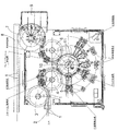
図1は、樹脂製キャップの外観検査機の全体構成を示す平面図である。図1に示すように、樹脂製キャップの外観検査機は、樹脂製キャップ1を搬入するシュート2と、シュート2からキャップ1を受け取って隣接するキャップ1の間に定間隔を形成する定間隔形成用スターホイール3と、定間隔形成用スターホイール3からキャップ1を受け取ってキャップ1を所定に検査部に搬入する検査用スターホイール4と、検査用スターホイール4からキャップ1を受け取ってキャップ1を円形軌道に沿って間欠的に搬送する回転割出装置(ロータリインデックスシステム)5を備えている。さらに、樹脂製キャップの外観検査機は、回転割出装置(ロータリインデックスシステム)5からキャップ1を受け取ってキャップ1を所定の検査部に搬入する検査用スターホイール6と、検査用スターホイール6からキャップ1を受け取って検査後のキャップ1を良品と不良品とに分けて排出するための排出用スターホイール7を備えている。排出用スターホイール7に隣接してコンベア8が設置されるとともに不良品用貯留部9が設置されている。
Hereinafter, an embodiment of a lighting device for a resin cap according to the present invention will be described with reference to FIGS. 1 to 14, the same or corresponding components are denoted by the same reference numerals, and redundant description is omitted.
FIG. 1 is a plan view showing the overall configuration of a resin cap appearance inspection machine. As shown in FIG. 1, a resin cap appearance inspection machine is configured to form a fixed interval between a chute 2 for carrying a
図1に示すように構成された樹脂製キャップの外観検査機において、キャップ1はシュート2によって連続的に定間隔形成用スターホイール3に供給され、ここで定間隔が形成された後、検査用スターホイール4に受け渡されるようになっている。検査用スターホイール4においてショートタブ検査や印刷検査が行われた後、キャップ1は回転割出装置(ロータリインデックスシステム)5に受け渡される。回転割出装置(ロータリインデックスシステム)5において、キャップの各種検査(後述する)が行われた後、キャップ1は検査用スターホイール6に受け渡される。検査用スターホイール6においてフレアーフラッシュ検査や内面検査が行われた後、キャップ1は排出用スターホイール7に受け渡される。そして、排出用スターホイール7によって良品はコンベア8に移送されコンベア8によって次工程に送られ、不良品は不良品用貯留部9に送られストックされるようになっている。
In the appearance inspection machine for resin caps configured as shown in FIG. 1, the
図1に示すように、回転割出装置5は略円板状のタレット板10を備え、タレット板10に所定間隔を置いて配置された複数の支持ユニット11が支持されている。複数の支持ユニット11は、タレット板10に設置されたカム機構等(図示せず)によって円形軌道に沿って間欠的に搬送されるようになっている。
As shown in FIG. 1, the
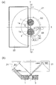
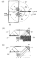
図2は、回転割出装置5および回転割出装置5の円形軌道に沿って配置された検査ステーションを示す平面図である。図2に示すように、回転割出装置5の円形軌道に沿って7つの検査ステーションS1〜S7が配置されている。7つの検査ステーションS1〜S7のうち、5つの検査ステーションS1,S3,S4,S5,S6には、照明装置および撮像装置(後述する)が設置されており、これらの検査ステーションにおいて外側面検査、プラグ検査、内側面検査、外形検査等の各種検査を行うようになっている。なお、検査ステーションS2,S7は、更に他の検査が必要な場合の予備ステーションになっている。各支持ユニット11は、回転割出装置5により間欠的に搬送されて7つの検査ステーションS1〜S7で停止するようになっている。
FIG. 2 is a plan view showing the
図3は回転割出装置5の要部斜視図である。図3に示すように、各支持ユニット11には、対(ペア)をなす2台の支持台12が設置されている。各支持台12は真空吸着用の孔12hを有し、この孔12hはロータリジョイント13およびチューブ14等を介して真空源(図示せず)に接続されており、真空吸着によってキャップ1の天面を保持するようになっている。すなわち、キャップ1は、天面を下にし開口部を上にした状態で支持台12により真空吸着によって保持される。なお、図3においては、支持台12に吸着されるキャップは図示を省略している。
図3に示すように、支持台12は下部に溝12aを有し、この溝12aに回転ベルト(図示せず)が嵌合するようになっている。そして、回転ベルトの走行によって支持台12が回転し、支持台12によって支持されたキャップ1が検査ステーションS1〜S7において360°以上自転されるようになっている。
FIG. 3 is a perspective view of a main part of the
As shown in FIG. 3, the
上述したように、回転割出装置5の各支持ユニット11には2個の支持台12が設置されている。通常、検査ステーションには、2個の支持台12に保持された2個のキャップ1に対して1台の照明装置および2台の撮像装置(後述する)が設置されている。そのため、各検査ステーションにおいて、同時に2個のキャップ1の検査が可能であり、キャップ1の検査処理数量を飛躍的に増加させることができる。
As described above, each
次に、図1乃至図3に示す樹脂製キャップの外観検査機における検査ステーションS1に設置された照明装置および撮像装置の構成について図4および図5を参照して説明する。
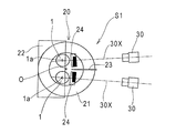
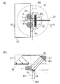
図4は検査ステーションS1の正面図であり、図5は検査ステーションS1の平面図である。図4および図5に示すように、2個の支持台12には、それぞれキャップ1が保持されている。各キャップ1は、天面を下にし開口部を上にした状態で支持台12により真空吸着によって保持されている。支持台12上の2個のキャップ1の上方および側方に、2個のキャップ1に共通の1台の照明装置20が設置されている。また、支持台12上の2個のキャップ1の側方に、2個のキャップ1の各々に対応して2台の撮像装置30,30が設置されている。
Next, the configuration of the illumination device and the imaging device installed in the inspection station S1 in the visual inspection machine for the resin cap shown in FIGS. 1 to 3 will be described with reference to FIGS. 4 and 5. FIG.
FIG. 4 is a front view of the inspection station S1, and FIG. 5 is a plan view of the inspection station S1. As shown in FIGS. 4 and 5, the
照明装置20は、対をなす2個のキャップ1の上方に水平に配置されたリング型RGB照明21と、リング型RGB照明21の直下に配置されるとともにリング型RGB照明21の下面の略半分を覆うように設置された矩形の板状体からなる第1遮光板22と、リング型RGB照明21の直下から鉛直方向に延びるとともにリング型RGB照明21の外周縁のやや外側からリング型RGB照明21の中心部に向かって延びる矩形の板状体からなる第2遮光板23と、リング型RGB照明21の斜め下方に配置されるとともにリング型RGB照明からの入射光を2個のキャップ1に向けて反射させる概略矩形の板状体からなる反射板24,24とから構成されている。リング型のRGB照明21は、リング型のRGB照明21の中心Oが2個のキャップ1の軸心1a,1aを結ぶ線分の中点から撮像装置30側に距離Lだけオフセット(偏倚)して配置されている。リング型RGB照明21は、水平面に対して所定の傾斜角(θ)で傾斜した円錐面Sに赤色LED、緑色LED、青色LEDをリング状に配列することにより構成されている。例えば、リング型RGB照明21は、赤色LEDを円周上に1列に並べた赤色LED列と、緑色LEDを円周上に1列に並べた緑色LED列と、青色LEDを円周上に1列に並べた青色LED列とを同心円状に円錐面に配列し、この配列を繰り返すことにより構成されている。
The illuminating
また、2台の撮像装置30,30は、2個のキャップ1に対応して配置されており、キャップ1の側方からキャップ1の外側面を撮像するようになっている。撮像装置30は白黒のCCDカメラから構成されており、撮像装置30の光軸30xはキャップ1の外側面の中央部に延びている。支持台12は回転・停止を繰り返すことができるようになっており、支持台12の停止中に、撮像装置30はキャップ1の外側面を所定角度分だけ撮影するようになっている。例えば、1枚の画像中に、キャップ1の外側面の略60°を撮影するように設定した場合には、キャップ1が1回転する間に、キャップ1は6回〜7回停止し、この停止中に6枚〜7枚のキャップ1の画像を撮るようになっている。
Further, the two
本発明の樹脂製キャップの外観検査機は、ロータリインデックス搬送方式(回転割出搬送方式)を採用するため高速搬送が困難である状況にも拘らず、検査処理数量を増加するため、キャップ1を支持して自転させる支持台12の数を2倍にし、かつ2台の支持台12を対(ペア)として間欠搬送する方式である。ところが、このように支持台12の数を2倍にした場合に、対(ペア)をなす2台の支持台12を近接した位置に配置しなければならない。この場合、キャップ外側面の汚れや異物付着の有無等を検査するキャップ外側面の外観検査を行う際、キャップ1つに対し1つのリング型照明を設ければ、キャップ外側面を均一に照明することができるが、2つのキャップは接近していてリング型照明を2つ設けることが困難であった。そこで、本発明の照明装置20においては、対をなす2個の支持台12上の2個のキャップ1の上方に、リング型RGB照明21を配置している。ところが、2つのキャップに対し、1つのリング型照明を設ける場合、キャップ外側面を均一に照明することができず、照明ムラが生じるという問題点がある。
The resin cap appearance inspection machine according to the present invention employs a rotary index transfer method (rotational index transfer method), so that the high-speed transfer is difficult. In this method, the number of
本発明は、単一のリング型RGB照明21を用いるにも拘らず、2つのキャップ1の外側面を照明ムラなく均一に照明するため、照明装置に種々の工夫を施したものである。リング型RGB照明21は、内外径、傾斜角、LED数等に応じて選定することが可能な一般的に市販されているものを使用することができる。
In the present invention, although the single ring
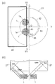
本発明の創案に至る過程を図6乃至図9を参照して説明する。図6は、リング型RGB照明21と対をなす2個のキャップ1との配置関係を示す図である。図6(a)は平面図であり、図6(b)は図6(a)のVI-VI線断面図である。図6においては、リング型RGB照明21の中心Oは、2個の支持台12上の2個のキャップ1の中間を通るX軸と、2個のキャップ1の軸心1a,1aを通るY軸との交点に位置している。すなわち、リング型RGB照明21の中心Oは、2個のキャップ1の軸心1a,1aを結ぶ線分の中点に位置している。リング型RGB照明21は、キャップ1のカメラ側の外側面を照明すれば良いので、リング型RGB照明21の直下にリング型RGB照明21の下面の略半分を覆うように矩形の板状体からなる第1遮光板22を配置している。
The process leading to the inventive idea will be described with reference to FIGS. FIG. 6 is a diagram showing an arrangement relationship between the two
図6に示す配置構成において、図6(a)に示す下側のキャップ1に着目すると、リング型RGB照明21により照明することにより、キャップ1の外側面上の領域A1およびその近傍には強い光が当たり、キャップ1の外側面上の領域A2およびその近傍には弱い光が当たる。これは、キャップ1の領域A1およびその近傍には、図6(a)において下側のキャップ1に近接したリング型RGB照明21の領域B1からの光ばかりでなく、上側のキャップ1に近接したリング型RGB照明21の領域B2からの光が入射し、さらに隣接するキャップ1からの反射光が入射するのに対し、キャップ1の領域A2およびその近傍には、図6(a)において下側のキャップ1に近接したリング型RGB照明21の領域B3からの光のみが入射するためである。
In the arrangement shown in FIG. 6, when attention is paid to the
上述の点について、図6(b)を参照して更に説明する。なお、リング型RGB照明21の上部からキャップ1に当たる照明を上部照明といい、リング型RGB照明21の下部からキャップ1に当たる照明を下部照明という。キャップ1の領域A1およびその近傍には、上側のキャップ1に近接したリング型RGB照明21の領域B2の照明(山越えの照明(上部照明))+下側のキャップ1に近接したリング型RGB照明21の領域B1の照明(下部照明)+隣接キャップの反射光が入射するため、強い照明となり、例えば強度を5段階で表せば最上位の「5」となる。これに対して、キャップ1の領域A2およびその近傍には、下側のキャップ1に近接したリング型RGB照明21の領域B3の照明(下部照明)のみが入射するため、弱い照明となり、強度は「1」となる。
The above points will be further described with reference to FIG. In addition, the illumination which hits the
以上のように、リング型RGB照明21の中心Oが検査対象の2個のキャップの軸心1a,1aを結ぶ線分の中点に位置するようにリング型RGB照明21を配置した場合には、キャップ1の外側面上の領域A2およびその近傍の照明が他の領域に比べてきわめて弱くなり、照明ムラが生じるという問題点がある。
As described above, when the ring
図7は、リング型RGB照明21の中心Oが2個のキャップ1の軸心1a,1aを結ぶ線分の中点からカメラ側(図7において右側)にオフセット(偏倚)するようにリング型RGB照明21を配置した構成を示す図である。図7(a)は平面図であり、図7(b)は図7(a)のVII-VII線断面図である。図7においては、リング型RGB照明21の中心Oは、2個のキャップ1の軸心1a,1aを結ぶ線分の中点からカメラ側にオフセット(偏倚)している。リング型RGB照明21は、キャップ1のカメラ側の外側面を照明すれば良いので、リング型RGB照明21の直下にリング型RGB照明21の下面の略半分を覆うように矩形の板状体からなる第1遮光板22を配置した構成は、図6と同様である。
FIG. 7 shows a ring type so that the center O of the ring
図7に示す配置構成において、図7(a)の下側のキャップ1に着目すると、リング型RGB照明21により照明することにより、キャップ1の外側面上の領域A1およびその近傍には依然として強い光が当たるが、図6における場合に比べると光の強度は弱まる。キャップ1の外側面上の領域A2およびその近傍に当たる光は他の領域に比べると依然として弱いが、図6における場合に比べると光の強度は少し強まる。図7(a)において、キャップ1の領域A1およびその近傍には、下側のキャップ1に近接したリング型RGB照明21の領域B1からの光と上側のキャップ1に近接したリング型RGB照明21の領域B2からの光とが入射するのに対し、キャップ1の領域A2およびその近傍には、下側のキャップ1に近接したリング型RGB照明21の領域B3からの光が入射する。
In the arrangement shown in FIG. 7, when attention is paid to the
上述の点について、図7(b)を参照して更に説明する。キャップ1の領域A1およびその近傍には、上側のキャップ1に近接したリング型RGB照明21の領域B2の照明(山越えの照明(上部照明))+下側のキャップ1に近接したリング型RGB照明21の領域B1の照明(下部照明)が入射するため、依然として強い照明となり、強度を5段階で表せば「4」となる。これに対して、キャップ1の領域A2およびその近傍には、下側のキャップ1に近接したリング型RGB照明21の領域B3(下部照明)のみが入射するため、依然として弱い照明であるが、リング型RGB照明21がカメラ側に偏倚しているので、キャップ1の領域A2およびその近傍にリング型RGB照明21の領域B3以外からも光が廻り込むため、キャップ1の領域A2およびその近傍に当たる光量が少し増加し、強度は「2」となる。従って照明ムラの問題点はやや改善されつつも依然として存在する。
The above points will be further described with reference to FIG. In the region A1 of the
図8は、図7の配置構成に第2の遮光板23を追加した配置構成を示す図である。図8(a)は平面図であり、図8(b)は図8(a)のVIIIA-VIIIA断面図であり、図8(c)は図8(a)のVIIIB-VIIIB線断面図である。図8に示す配置構成においては、リング型RGB照明21の直下から鉛直方向に延びるとともにリング型RGB照明21の外周縁のやや外側からリング型RGB照明21の中心部に向かって延びる矩形の板状体からなる第2遮光板23が設けられている。リング型RGB照明21の中心Oを2個のキャップ1の軸心1a,1aを結ぶ線分の中点からカメラ側にオフセット(偏倚)させ、リング型RGB照明21の直下にリング型RGB照明21の下面の略半分を覆うように矩形の板状体からなる第1遮光板22を配置した構成は、図7と同様である。
FIG. 8 is a diagram illustrating an arrangement configuration in which a second
図8に示す配置構成において、図8(a)の下側のキャップ1に着目すると、リング型RGB照明21により照明することにより、キャップ1の外側面上の領域A1およびその近傍に当たる光の一部は第2遮光板23によって遮られる。すなわち、リング型RGB照明21の領域B2からの光は、第2遮光板23により遮られるため、キャップ1の領域A1およびその近傍には入射しない。キャップ1の外側面上の領域A2およびその近傍に当たる光は、図7の場合と同一である。図8(a)において、キャップ1の領域A1およびその近傍には、下側のキャップ1に近接したリング型RGB照明21の領域B1からの光が入射し、キャップ1の領域A2およびその近傍には、下側のキャップ1に近接したリング型RGB照明21の領域B3からの光が入射する。
In the arrangement shown in FIG. 8, when attention is paid to the
上述の点について、図8(b)及び図8(c)を参照して更に説明する。上側のキャップ1に近接したリング型RGB照明21の領域B2の照明(山越えの照明(上部照明))は第2遮光板23によって遮られ、キャップ1の領域A1およびその近傍には入射しない。キャップ1の領域A1およびその近傍には、下側のキャップ1に近接したリング型RGB照明21の領域B1からの光が入射するため、強度を5段階で表せば「3」となる。これに対して、キャップ1の領域A2およびその近傍には、図7における場合と同様に、下側のキャップ1に近接したリング型RGB照明21の領域B3(下部照明)からの光のみが入射するため、強度は「2」となる。したがって、照明ムラの問題は、撮影には支障が生じない程度に改善されている。
The above points will be further described with reference to FIGS. 8B and 8C. The illumination in the region B2 of the ring-
図9は、図8の配置構成に反射板24を追加した配置構成を示す図である。図9(a)は平面図であり、図9(b)は図9(a)のIX-IX線断面図である。図9に示す配置構成においては、対をなす2個のキャップ1の斜め下方に水平に配置された概略矩形の板状体からなる反射板24が設けられている。反射板24は、キャップ1の領域A1に近接した側の幅W1は小さく、キャップ1の領域A2に近接した側の幅W2は大きく設定されている。図9(a)において第2遮光板23を境として、反射板24の手前側は略L字状に形成されており、反射板24の奥側は逆L字状に形成されている。リング型RGB照明21の中心Oを2個のキャップ1の軸心1a,1aを結ぶ線分の中点からカメラ側にオフセット(偏倚)させ、リング型RGB照明21の直下にリング型RGB照明21の下面の略半分を覆うように矩形の板状体からなる第1遮光板22を配置し、リング型RGB照明21の直下から鉛直方向に延びるとともにリング型RGB照明21の外周縁のやや外側からリング型RGB照明21の中心部に向かって延びる矩形の板状体からなる第2遮光板23を配置した構成は、図8と同様である。なお、図9では反射板24は一枚の矩形の板状体としているが、図5に示すように反射板24は2枚に分かれていてもよい。また、一枚の矩形の板状体上に遮光板(図9において黒塗りで示す)を配置して、上記略L字状および逆L字状の2つの部分を形成している。
FIG. 9 is a diagram showing an arrangement configuration in which a
図9に示す配置構成において、図9(a)の下側のキャップ1に着目すると、反射板24は幅W1を有した部分においてリング型RGB照明21からの光を反射して反射光をキャップ1の領域A1およびその近傍の下部側に入射させる。これにより、キャップ1の領域A1およびその近傍における下部側がやや明るくなり、下部側と上部側の照明が略同一の強度となる。また、反射板24は、幅W2を有した部分においてリング型RGB照明21からの光を反射して反射光をキャップ1の領域A2およびその近傍の上下部に入射させる。これにより、キャップ1の領域A2およびその近傍における上下部の照明の強度が向上する。
In the arrangement shown in FIG. 9, when focusing on the
上述の点について、図9(b)を参照して更に説明する。キャップ1の領域A1およびその近傍は、図8の配置構成においては下部側が上部側よりわずかに暗かったが、反射板24を設置することにより、反射板24の幅W1の部分からの反射光によりこの照明ムラが改善される。これに対して、キャップ1の領域A2およびその近傍の上下部には、下側のキャップ1に近接したリング型RGB照明21の領域B3(下部照明)からの光が入射し、さらに反射板24によって反射した光が入射するため、強度は「3」となる。従って、照明ムラの問題は解消される。
The above points will be further described with reference to FIG. The area A1 of the
次に、図5に示すように構成された照明装置20および撮像装置30を用いて種々の色のキャップ1を撮影した画像を図10乃至図14を参照して説明する。
従来、樹脂製キャップは白色が主流であったが、最近では白色に限らず、青色、赤色等の様々な色が用いられている。そのため、従来用いていたハロゲン照明と白黒のCCDカメラとの組合せでは、画像上では欠陥としての特徴が得られない場合がある。そこで、本発明においては、赤色LED、緑色LED、青色LEDをリング状に配列したリング型RGB照明21を用いている。そして、赤色LED、緑色LED、青色LEDの点灯・消灯を適宜組合せることによって、所望の色調に調光することができる。すなわち、樹脂製キャップの色に応じて、欠陥が際立つようにコントラストが強調できるような配色に照明を調光でき、様々な色のキャップについて外側面の検査を行うことが可能である。
Next, images obtained by photographing the
Conventionally, the resin cap has been mainly white, but recently, not only white but various colors such as blue and red are used. For this reason, there is a case where a feature as a defect cannot be obtained on an image by a combination of a conventionally used halogen illumination and a monochrome CCD camera. Therefore, in the present invention, the ring
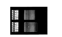
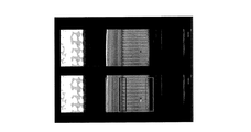
図10は、白色のキャップの外側面に付着した茶色の汚れを検出する場合の画像を示す図である。図10は、リング型RGB照明21における青色LEDのみを点灯してキャップ1を撮像装置30により撮影した画像を示す図であり、上側の画像は撮像装置30により撮影した画像そのものであり、下側の画像は撮像装置30により撮影した画像に検査領域(図示例では5個の検査領域)を設定し、欠陥部(茶色の汚れ)にロジック信号をのせてオーバレイ表示した検査用画像である。図10に示すように、上下の画像ともに、欠陥部(茶色の汚れ)が明瞭に識別できる画像が得られている。
図4に示すように、撮像装置30は、被写体であるキャップ1に対して、下から見上げるように上に向けて配置されている。すなわち、カメラアングルはローアングルに設定されているため、図10に示すように、撮像装置30により得られた画像の左側部分には点灯しているLEDが撮影されている。図10では、青色LED列のみが点灯している状態が示されている。
FIG. 10 is a diagram illustrating an image when brown stains attached to the outer surface of the white cap are detected. FIG. 10 is a diagram showing an image obtained by photographing only the blue LED in the ring-
As shown in FIG. 4, the
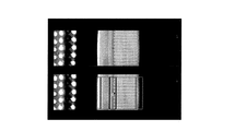
図11は、赤色のキャップの外側面に付着した黒色の汚れを検出する場合の画像を示す図である。図11は、リング型RGB照明21における赤色LEDと青色LEDを点灯してキャップ1を撮像装置30により撮影した画像を示す図であり、上側の画像は撮像装置30により撮影した画像そのものであり、下側の画像は撮像装置30により撮影した画像に検査領域(図示例では5個の検査領域)を設定し、欠陥部(黒色の汚れ)にロジック信号をのせてオーバレイ表示した検査用画像である。図11に示すように、上下の画像ともに、欠陥部(黒色の汚れ)が明瞭に識別できる画像が得られている。
図11に示すように、撮像装置30により得られた画像の左側部分には点灯しているLEDが撮影されている。図11では、赤色LED列と青色LED列が点灯している状態が示されている。
FIG. 11 is a diagram illustrating an image when black stains attached to the outer surface of the red cap are detected. FIG. 11 is a diagram illustrating an image obtained by lighting the red LED and the blue LED in the ring
As shown in FIG. 11, a lit LED is photographed on the left side of the image obtained by the
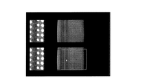
図12は、青色のキャップの外側面に付着した黒色の汚れを検出する場合の画像を示す図である。図12は、リング型RGB照明21における赤色LEDと青色LEDを点灯してキャップ1を撮像装置30により撮影した画像を示す図であり、上側の画像は撮像装置30により撮影した画像そのものであり、下側の画像は撮像装置30により撮影した画像に検査領域(図示例では5個の検査領域)を設定し、欠陥部(黒色の汚れ)にロジック信号をのせてオーバレイ表示した検査用画像である。図12に示すように、上下の画像ともに、欠陥部(黒色の汚れ)が明瞭に識別できる画像が得られている。
図12に示すように、撮像装置30により得られた画像の左側部分には点灯しているLEDが撮影されている。図12では、赤色LED列と青色LED列が点灯している状態が示されている。
FIG. 12 is a diagram illustrating an image when black stains attached to the outer surface of the blue cap are detected. FIG. 12 is a diagram illustrating an image obtained by lighting the red LED and the blue LED in the ring
As shown in FIG. 12, a lit LED is photographed on the left side of the image obtained by the
図13は、灰色のキャップの外側面に付着した黒色の汚れを検出する場合の画像を示す図である。図13は、リング型RGB照明21における赤色LEDと緑色LEDと青色LEDを点灯してキャップ1を撮像装置30により撮影した画像を示す図であり、上側の画像は撮像装置30により撮影した画像そのものであり、下側の画像は撮像装置30により撮影した画像に検査領域(図示例では5個の検査領域)を設定し、欠陥部(黒色の汚れ)にロジック信号をのせてオーバレイ表示した検査用画像である。図13に示すように、上下の画像ともに、欠陥部(黒色の汚れ)が明瞭に識別できる画像が得られている。
図13に示すように、撮像装置30により得られた画像の左側部分には点灯しているLEDが撮影されている。図13では、赤色LED列と緑色LED列と青色LED列が点灯している状態が示されている。
FIG. 13 is a diagram illustrating an image when black stains attached to the outer surface of the gray cap are detected. FIG. 13 is a diagram illustrating an image obtained by lighting the red LED, the green LED, and the blue LED in the ring
As shown in FIG. 13, a lit LED is photographed on the left side of the image obtained by the
図14は、黄緑色のキャップの外側面に付着した青色の汚れを検出する場合の画像を示す図である。図14は、リング型RGB照明21における緑色LEDと青色LEDを点灯してキャップ1を撮像装置30により撮影した画像を示す図であり、上側の画像は撮像装置30により撮影した画像そのものであり、下側の画像は撮像装置30により撮影した画像に検査領域(図示例では5個の検査領域)を設定し、欠陥部(青色の汚れ)にロジック信号をのせてオーバレイ表示した検査用画像である。図14に示すように、上下の画像ともに、欠陥部(青色の汚れ)が明瞭に識別できる画像が得られている。
図14に示すように、撮像装置30により得られた画像の左側部分には点灯しているLEDが撮影されている。図14では、緑色LED列と青色LED列が点灯している状態が示されている。
FIG. 14 is a diagram illustrating an image when blue stains attached to the outer surface of the yellow-green cap are detected. FIG. 14 is a diagram illustrating an image obtained by lighting the green LED and the blue LED in the ring
As shown in FIG. 14, a lit LED is photographed on the left side of the image obtained by the
以上説明したように、本発明においては、赤色LED、緑色LED、青色LEDをリング状に配列したリング型RGB照明21を用い、赤色LED、緑色LED、青色LEDの点灯・消灯を適宜組合せることによって、所望の色調に調光することができる。すなわち、樹脂製キャップの色に応じて、欠陥が際立つようにコントラストが強調できるような配色に照明を調光でき、様々な色のキャップについて外側面に付着した様々な色の汚れを検出することが可能である。
As described above, in the present invention, the ring
これまで本発明の実施形態について説明したが、本発明は上述の実施形態に限定されず、その技術思想の範囲内において、種々の異なる形態で実施されてよいことは勿論である。 Although the embodiment of the present invention has been described so far, the present invention is not limited to the above-described embodiment, and it is needless to say that the present invention may be implemented in various different forms within the scope of the technical idea.
1 樹脂製キャップ
1a 軸心
2 シュート
3 定間隔形成用スターホイール
4 検査用スターホイール
5 回転割出装置(ロータリインデックスシステム)
6 検査用スターホイール
7 排出用スターホイール
8 コンベア
9 不良品用貯留部
10 タレット板
11 支持ユニット
12 支持台
12a 溝
12h 孔
13 ロータリジョイント
14 チューブ
15 回転ベルト
16 プーリ
20 照明装置
21 リング型RGB照明
22 第1遮光板
23 第2遮光板
24 反射板
30 撮像装置
30x 光軸
S1,S2,S3,S4,S5,S6,S7 検査ステーション
DESCRIPTION OF
6 Star wheel for inspection 7 Star wheel for discharge 8
Claims (6)
対をなす2個の樹脂製キャップの上方に水平に配置されたリング型RGB照明と、
前記リング型RGB照明の直下に配置されるとともに、前記リング型RGB照明の略半分を覆うように前記撮像装置から離間した側に配置される第1遮光板と、
前記リング型RGB照明の直下に鉛直に配置されるとともに、前記リング型RGB照明の外周縁から中心部に向かって樹脂製キャップの搬送方向と略直交する方向に延びる第2遮光板とを備え、
前記リング型RGB照明は、リング型RGB照明の中心が前記対をなす2個のキャップの軸心を結ぶ線分の中点から撮像装置側に偏倚するように配置されていることを特徴とする樹脂製キャップの照明装置。 Illumination installed at the inspection station of the inspection machine that inspects the resin cap with the imaging device that conveys the resin cap intermittently along the circular path and images the resin cap from the side at the inspection station at the stop position In the device
A ring type RGB illumination horizontally disposed above two paired resin caps;
A first light-shielding plate disposed immediately below the ring-type RGB illumination and disposed on a side away from the imaging device so as to cover substantially half of the ring-type RGB illumination;
A second light-shielding plate that is vertically disposed immediately below the ring-type RGB illumination and extends in a direction substantially orthogonal to the transport direction of the resin cap from the outer peripheral edge of the ring-type RGB illumination toward the center,
The ring-type RGB illumination is arranged such that the center of the ring-type RGB illumination is biased toward the image pickup apparatus from the midpoint of the line segment connecting the axis centers of the two caps forming the pair. Resin cap lighting device.
請求項1乃至4のいずれか1項に記載の照明装置と、
前記2台の支持台上の対をなす2個の樹脂製キャップに対応して設置された撮像装置とを備えたことを特徴とする樹脂製キャップの外観検査機。 A rotary indexing device that intermittently conveys a plurality of support units that support two support bases that support two paired resin caps;
The lighting device according to any one of claims 1 to 4,
An appearance inspection machine for a resin cap, comprising: an imaging device installed corresponding to the two resin caps forming a pair on the two support bases.
Priority Applications (1)
| Application Number | Priority Date | Filing Date | Title |
|---|---|---|---|
| JP2009222423A JP2011069771A (en) | 2009-09-28 | 2009-09-28 | Lighting system of resin cap |
Applications Claiming Priority (1)
| Application Number | Priority Date | Filing Date | Title |
|---|---|---|---|
| JP2009222423A JP2011069771A (en) | 2009-09-28 | 2009-09-28 | Lighting system of resin cap |
Publications (1)
| Publication Number | Publication Date |
|---|---|
| JP2011069771A true JP2011069771A (en) | 2011-04-07 |
Family
ID=44015170
Family Applications (1)
| Application Number | Title | Priority Date | Filing Date |
|---|---|---|---|
| JP2009222423A Pending JP2011069771A (en) | 2009-09-28 | 2009-09-28 | Lighting system of resin cap |
Country Status (1)
| Country | Link |
|---|---|
| JP (1) | JP2011069771A (en) |
Cited By (3)
| Publication number | Priority date | Publication date | Assignee | Title |
|---|---|---|---|---|
| JP2017120201A (en) * | 2015-12-28 | 2017-07-06 | キリンテクノシステム株式会社 | Inspection method of cap having bridge, and inspection device of cap |
| CN109975309A (en) * | 2019-03-20 | 2019-07-05 | 上海大学 | It is a kind of based on machine vision to the template matching detection method of six bridge defect of aluminium lid |
| JP2020180885A (en) * | 2019-04-25 | 2020-11-05 | キリンテクノシステム株式会社 | Cap inspection method and inspection system |
-
2009
- 2009-09-28 JP JP2009222423A patent/JP2011069771A/en active Pending
Cited By (3)
| Publication number | Priority date | Publication date | Assignee | Title |
|---|---|---|---|---|
| JP2017120201A (en) * | 2015-12-28 | 2017-07-06 | キリンテクノシステム株式会社 | Inspection method of cap having bridge, and inspection device of cap |
| CN109975309A (en) * | 2019-03-20 | 2019-07-05 | 上海大学 | It is a kind of based on machine vision to the template matching detection method of six bridge defect of aluminium lid |
| JP2020180885A (en) * | 2019-04-25 | 2020-11-05 | キリンテクノシステム株式会社 | Cap inspection method and inspection system |
Similar Documents
| Publication | Publication Date | Title |
|---|---|---|
| US9329135B2 (en) | Means for inspecting glass containers for defects | |
| US7414716B2 (en) | Machine for inspecting glass containers | |
| JP4374051B2 (en) | Article visual inspection apparatus and surface inspection apparatus | |
| US8058607B2 (en) | Machine for inspecting glass containers at an inspection station using an addition of a plurality of illuminations of reflected light | |
| JP2006308437A (en) | Device and method for inspecting foreign matter | |
| JP4713279B2 (en) | Illumination device and visual inspection apparatus equipped with the same | |
| EP1988386B1 (en) | Machine and method for inspecting glass containers | |
| US7541572B2 (en) | Machine for inspecting rotating glass containers with light source triggered multiple times during camera exposure time | |
| CN110546486B (en) | Inspection machine | |
| EP1988387B1 (en) | Machine for inspecting glass containers | |
| JP2011069771A (en) | Lighting system of resin cap | |
| US7876951B2 (en) | Machine for inspecting glass containers | |
| JP2005017003A (en) | Vial inspection system | |
| JP4743816B2 (en) | Container inspection device | |
| CN113533376B (en) | Glass bottle breakage defect detection system and detection method | |
| EP1916514B1 (en) | Machine for inspecting glass containers | |
| EP1916515B1 (en) | Machine for inspecting glass containers | |
| JP2006084481A5 (en) | ||
| JP2017227537A (en) | Visual inspection device, visual inspection method and surface inspection device | |
| JP5974575B2 (en) | Mouth inspection device and mouth inspection method | |
| JP4131463B2 (en) | Lighting equipment for container inspection | |
| JP2002267612A (en) | Device and system for inspecting foreign matter in liquid filled in transparent container or the like | |
| JP2010175558A (en) | Inspection device | |
| KR20180061149A (en) | Apparatus and method for checking product conformity | |
| JP2011257324A (en) | Glass bottle inspecting device |