JP2011069172A - Method for constructing building - Google Patents
Method for constructing building Download PDFInfo
- Publication number
- JP2011069172A JP2011069172A JP2009223150A JP2009223150A JP2011069172A JP 2011069172 A JP2011069172 A JP 2011069172A JP 2009223150 A JP2009223150 A JP 2009223150A JP 2009223150 A JP2009223150 A JP 2009223150A JP 2011069172 A JP2011069172 A JP 2011069172A
- Authority
- JP
- Japan
- Prior art keywords
- upper plate
- upper structure
- bolt
- fixed
- seismic isolation
- Prior art date
- Legal status (The legal status is an assumption and is not a legal conclusion. Google has not performed a legal analysis and makes no representation as to the accuracy of the status listed.)
- Pending
Links
- 238000000034 method Methods 0.000 title claims description 5
- 238000002955 isolation Methods 0.000 claims description 22
- 238000005452 bending Methods 0.000 claims description 4
- 238000009435 building construction Methods 0.000 claims description 4
- 238000010276 construction Methods 0.000 abstract description 7
- 229910000831 Steel Inorganic materials 0.000 description 9
- 239000010959 steel Substances 0.000 description 9
- 239000004567 concrete Substances 0.000 description 4
- 238000010008 shearing Methods 0.000 description 3
- 238000003466 welding Methods 0.000 description 2
- 238000009434 installation Methods 0.000 description 1
- 239000000463 material Substances 0.000 description 1
- 239000011150 reinforced concrete Substances 0.000 description 1
- 238000000926 separation method Methods 0.000 description 1
Images
Landscapes
- Buildings Adapted To Withstand Abnormal External Influences (AREA)
Abstract
Description
下基礎上に免震装置を設置し、免震装置の上部プレート上に上部構造物を載置した後、上部構造物を上部プレートに固定する建物の施工方法に関する。 The present invention relates to a building construction method in which a base isolation device is installed on a lower foundation, an upper structure is placed on an upper plate of the base isolation device, and then the upper structure is fixed to the upper plate.
一般に、鉄骨構造や鉄骨鉄筋コンクリート構造において、施工中の組み立て誤差を許容値内に納めるため、建ち直しによって位置修正を行なう必要がある。
従来、前記上部プレート上に仮設のH形鋼などの鋼材を溶接により取付け、そのH形鋼上に上部構造物を載置して、上部構造物をH形鋼とをボルト等で固定し、上部構造物の柱位置の確定後に、上部プレートと上部構造物とを本固定するか、もしくは、上部プレート上に鉄骨梁や柱などの下端に溶接した固定板を介して載置し、その上部プレートと固定板とをボルト連結により固定していた(例えば、特許文献1参照)。
Generally, in a steel structure or a steel reinforced concrete structure, it is necessary to correct the position by rebuilding in order to keep assembly errors during construction within an allowable value.
Conventionally, a steel material such as a temporary H-section steel is attached to the upper plate by welding, an upper structure is placed on the H-section steel, and the upper structure is fixed to the H-section steel with a bolt or the like. After determining the column position of the upper structure, either fix the upper plate and the upper structure in place, or place them on the upper plate via a fixing plate welded to the lower end of a steel beam, column, etc. The plate and the fixing plate are fixed by bolt connection (for example, see Patent Document 1).
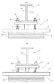
上述した従来の施工方法では、いずれも、柱位置の確定時に上部構造物を位置修正した場合、位置修正量が多ければ、固定ボルトや溶接部を介して図3(a)〜(b)に示すように、免震装置2に過大な剪断変形を発生させる可能性がある。
その状態で上部プレート4上に上基礎のコンクリート等を構築すると、免震装置2に剪断変形と内部応力を発生させた状態(図3(b))で、構造体を固定してしまうことになり、突然の地震時に設計通りの免震性能が発揮されなくなる虞がある。
In any of the conventional construction methods described above, when the position of the upper structure is corrected at the time of determining the column position, if the amount of position correction is large, it is shown in FIGS. As shown, there is a possibility of causing excessive shear deformation in the
If the upper foundation concrete or the like is constructed on the
従って、本発明の目的は、上記問題点を解消し、施工中の上部構造物の位置修正によっても免震装置に過大な変形や応力を発生させないようにするところにある。 Accordingly, an object of the present invention is to eliminate the above-mentioned problems and prevent excessive deformation and stress from being generated in the seismic isolation device even by correcting the position of the superstructure during construction.
本発明の第1の特徴構成は、下基礎上に免震装置を設置し、前記免震装置の上部プレートに仮固定部を介して上部構造物を載置して仮固定し、前記上部構造物の柱位置の確定後に前記上部プレートと前記上部構造物とを本固定するにあたり、前記仮固定部を形成するに、曲げ変形可能なボルトを前記上部プレート上に上方に向けて突出した状態で固定すると共に、前記上部プレート上に前記上部構造物の下端に連結した束立てを横移動自在に載置し、前記ボルトに前記上部構造物を連結するところにある。 According to a first characteristic configuration of the present invention, a seismic isolation device is installed on a lower foundation, and an upper structure is placed and temporarily fixed to an upper plate of the seismic isolation device via a temporary fixing portion. When the upper plate and the upper structure are permanently fixed after the column position of the object is determined, the temporary fixing portion is formed with a bendable bolt projecting upward on the upper plate. While fixing, the bundling connected to the lower end of the upper structure is placed on the upper plate so as to be laterally movable, and the upper structure is connected to the bolt.
本発明の第1の特徴構成によれば、上部構造物は、束立てを介して上部プレート上に載置した状態で、その荷重を免震装置に支持させながら、ボルトを介して上部プレートに連結する。このために、上方への浮上りは阻止され、従って、上部構造物の施工中の転倒などは防止される。
その上、施工中の上部構造物の位置修正時には、上部構造物に作用する横方向の外力に対して、ボルトが曲げ変形しながら束立てを介して上部構造物の横移動を許容し、免震装置に対する剪断作用は防止される。
従って、免震装置に内部応力が発生することなく、所定の免震性能を期待できる建物を施工できる。
According to the first characteristic configuration of the present invention, the upper structure is placed on the upper plate via the bundling, and the load is supported on the upper plate via the bolt while supporting the load on the seismic isolation device. Link. For this reason, the upward lift is prevented, and thus the fall or the like during construction of the superstructure is prevented.
In addition, when correcting the position of the superstructure under construction, the lateral movement of the superstructure is permitted through bundling while the bolt is bent and deformed against the lateral external force acting on the superstructure. Shearing action on the seismic device is prevented.
Therefore, it is possible to construct a building that can expect a predetermined seismic isolation performance without generating internal stress in the seismic isolation device.
本発明の第2の特徴構成は、前記ボルトは、前記上部プレートに固定するスタッドボルトであって、柱位置の確定操作時に、前記上部構造物の位置修正に伴う曲げ変形を許容するものであるところにある。 According to a second characteristic configuration of the present invention, the bolt is a stud bolt that is fixed to the upper plate, and allows bending deformation accompanying position correction of the upper structure during a column position fixing operation. By the way.
本発明の第2の特徴構成によれば、本発明の第1の特徴構成による上述の作用効果を叶えることができるのに加えて、曲げ変形を許容できるスタッドボルトを上部プレートに取付けることにより、簡単な施工で前記目的を実現することが可能となる。 According to the second characteristic configuration of the present invention, in addition to being able to achieve the above-described operation effect according to the first characteristic configuration of the present invention, by attaching a stud bolt capable of bending deformation to the upper plate, The object can be realized by simple construction.
本発明の第3の特徴構成は、前記束立てに、前記上部プレートに対する載置部を出退自在な上下レベル調整機構を設けてあるところにある。 A third characteristic configuration of the present invention resides in that a vertical level adjusting mechanism is provided on the bundling so that the mounting portion with respect to the upper plate can be moved back and forth.
本発明の第3の特徴構成によれば、複数の免震装置の設置箇所で、上部プレートと上部構造との離間距離を、夫々個別に調整でき、柱の上下位置も微調整できる。 According to the third characteristic configuration of the present invention, the separation distance between the upper plate and the upper structure can be individually adjusted and the vertical position of the column can be finely adjusted at the installation locations of the plurality of seismic isolation devices.
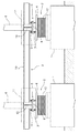
以下に本発明の実施の形態を、図1〜図2に基づいて説明する。
図1は、場所打ちコンクリート杭等のフーチングからなる下基礎1上に、積層ゴム支承からなる免震装置2が予め用意したアンカーボルトで固定して設置される。もっとも、下基礎1は、場所打ちコンクリート杭に限らず、免震構造物の基礎に採用可能な公知の種々の基礎についても同様に実施できる。
前記免震装置2上には、上部構造物3が設置されるのであるが、まず、免震装置2の上部プレートに仮固定部5を介して上部構造物3を載置して仮固定し、上部構造物3の組み付けに伴って生じる上部構造物3の柱6の位置確定操作後に、上部構造物3と上部プレートとを本固定する。
つまり、上部構造物3は、S造又はSRC造で、鉄骨10の組み立て後に位置修正が必要な時に、建ち修正ワイヤー等でわずかに横移動させることがある。その際に、免震装置2に過大な剪断力が作用して変形しようとするのを防止するために、仮固定部5を次のように構成する。
Embodiments of the present invention will be described below with reference to FIGS.
In FIG. 1, a
The
That is, when the
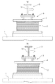
上部構造物3の位置修正に伴う横方向の外力で曲げ変形を許容するスタッドボルト7を、免震装置2の上部プレート上に上方に向けて突出した状態で固定する。
組み立てアングル等で形成した束立て8を、上部構造物3の下端に溶接で連結し、その束立て8の下側先端を横移動自在に上部プレート上に載置して、上部構造物3の荷重を上部プレートに支持させる。
上部構造物3が転倒しないように、スタッドボルト7上端部に上部構造物3をナット9で連結する。このように、束立て8とスタッドボルト7で上部構造物3の仮固定部5を形成する。
A stud bolt 7 that allows bending deformation by a lateral external force accompanying the position correction of the
A
The
上部構造物3の組み立て及び位置修正に基づく柱6の位置確定後には、上部プレートに取り付けた複数のアンカーを介して、上部構造物3の鉄骨10と上部プレートとを本固定すべくコンクリートで一体化して、上基礎部分11を形成する。
尚、前記位置修正時に作用する横方向の外力により、図2(b)に示すように、束立て8が横に滑動しながらスタッドボルト7は曲げ変形して、免震装置2の積層ゴム12には剪断力が伝わらないようにしてある。
After the position of the
Note that, as shown in FIG. 2B, the stud bolt 7 is bent and deformed while the
〔別実施形態〕
以下に他の実施の形態を説明する。
[Another embodiment]
Other embodiments will be described below.
〈1〉 前記束立て8は、上部プレートに対する載置部を出退自在な上下レベル調整機構を設けてあってもよい。
〈2〉 前記スタッドボルト7に代えて一般的な頭付きボルトを上部プレートに固定してあっても良く、それらをボルトと総称する。
尚、上述のように、図面との対照を便利にするために符号を記したが、該記入により本発明は添付図面の構成に限定されるものではない。また、本発明の要旨を逸脱しない範囲において、種々なる態様で実施し得ることは勿論である。
<1> The
<2> Instead of the stud bolt 7, general headed bolts may be fixed to the upper plate, and these are collectively referred to as bolts.
In addition, as mentioned above, although the code | symbol was written in order to make contrast with drawing convenient, this invention is not limited to the structure of an accompanying drawing by this entry. In addition, it goes without saying that the present invention can be carried out in various modes without departing from the gist of the present invention.
1 下基礎
2 免震装置
3 上部構造物
4 上部プレート
5 仮固定部
6 柱
7 スタッドボルト
8 束立て
DESCRIPTION OF SYMBOLS 1
Claims (3)
前記免震装置の上部プレートに仮固定部を介して上部構造物を載置して仮固定し、
前記上部構造物の柱の位置確定後に前記上部プレートと前記上部構造物とを本固定するにあたり、
前記仮固定部を形成するに、曲げ変形可能なボルトを前記上部プレート上に上方に向けて突出した状態で固定すると共に、前記上部プレート上に前記上部構造物の下端に連結した束立てを横移動自在に載置し、
前記ボルトに前記上部構造物を連結する建物の施工方法。 Install seismic isolation devices on the lower foundation,
The upper structure is placed and temporarily fixed to the upper plate of the seismic isolation device via the temporary fixing portion,
In fixing the upper plate and the upper structure after fixing the position of the pillar of the upper structure,
In order to form the temporary fixing portion, a bendable bolt is fixed in a state of protruding upward on the upper plate, and a bundling connected to the lower end of the upper structure is horizontally placed on the upper plate. Place it movably,
A building construction method for connecting the superstructure to the bolt.
Priority Applications (1)
| Application Number | Priority Date | Filing Date | Title |
|---|---|---|---|
| JP2009223150A JP2011069172A (en) | 2009-09-28 | 2009-09-28 | Method for constructing building |
Applications Claiming Priority (1)
| Application Number | Priority Date | Filing Date | Title |
|---|---|---|---|
| JP2009223150A JP2011069172A (en) | 2009-09-28 | 2009-09-28 | Method for constructing building |
Publications (1)
| Publication Number | Publication Date |
|---|---|
| JP2011069172A true JP2011069172A (en) | 2011-04-07 |
Family
ID=44014684
Family Applications (1)
| Application Number | Title | Priority Date | Filing Date |
|---|---|---|---|
| JP2009223150A Pending JP2011069172A (en) | 2009-09-28 | 2009-09-28 | Method for constructing building |
Country Status (1)
| Country | Link |
|---|---|
| JP (1) | JP2011069172A (en) |
Citations (4)
| Publication number | Priority date | Publication date | Assignee | Title |
|---|---|---|---|---|
| JPH09177366A (en) * | 1995-12-25 | 1997-07-08 | Hazama Gumi Ltd | Joining structure of steel frame reinforced concrete column and seismic isolation device and joining method |
| JPH09279599A (en) * | 1996-04-10 | 1997-10-28 | Sekisui Chem Co Ltd | Construction method of foundation for unit building and bolt cover used for the method |
| JPH10121746A (en) * | 1996-10-23 | 1998-05-12 | Okumura Corp | Seismic isolation structure of existing building |
| JP2000073443A (en) * | 1998-08-31 | 2000-03-07 | Yoshifumi Hayashi | Load support device having function for deciding position for steel frame column and function for adjusting level |
-
2009
- 2009-09-28 JP JP2009223150A patent/JP2011069172A/en active Pending
Patent Citations (4)
| Publication number | Priority date | Publication date | Assignee | Title |
|---|---|---|---|---|
| JPH09177366A (en) * | 1995-12-25 | 1997-07-08 | Hazama Gumi Ltd | Joining structure of steel frame reinforced concrete column and seismic isolation device and joining method |
| JPH09279599A (en) * | 1996-04-10 | 1997-10-28 | Sekisui Chem Co Ltd | Construction method of foundation for unit building and bolt cover used for the method |
| JPH10121746A (en) * | 1996-10-23 | 1998-05-12 | Okumura Corp | Seismic isolation structure of existing building |
| JP2000073443A (en) * | 1998-08-31 | 2000-03-07 | Yoshifumi Hayashi | Load support device having function for deciding position for steel frame column and function for adjusting level |
Similar Documents
| Publication | Publication Date | Title |
|---|---|---|
| JP6612014B2 (en) | Seismic reinforcement device, seismic reinforcement structure, earthquake-resistant building, seismic reinforcement method | |
| JP6111922B2 (en) | Column base reinforcement method and apparatus | |
| JP2007023626A (en) | Vibration-controlled base-isolated structure | |
| JP2011074604A (en) | Bridge movement restraining apparatus and movement restraining method | |
| JP4472726B2 (en) | Base-isolated building structure | |
| JP7095838B2 (en) | Pile column joint structure and construction method of pile column joint structure | |
| JP2011256695A (en) | Column capital base isolation structure | |
| JP2014020071A (en) | Seismic strengthening method for reinforced-concrete anchor part of steel bridge pier | |
| JP2005299080A (en) | Earthquake-resistant bridge pier | |
| JP4657028B2 (en) | Joining structure and joining method of pile and superstructure | |
| JP5325709B2 (en) | Method of constructing steel exposed column base structure | |
| JP2006077492A (en) | Earthquake resisting pier | |
| JP2011069172A (en) | Method for constructing building | |
| JP4672459B2 (en) | Building reinforcement method | |
| JP4324085B2 (en) | Seismic strengthening method and seismic strengthening structure for all directions of piers in existing bridges | |
| JP5458375B2 (en) | Base isolation structure | |
| JP3789915B2 (en) | Base isolation structure | |
| JP2008231753A (en) | Temporary fixing device of base-isolating layer | |
| JP3733517B2 (en) | Seismic isolation device mounting structure | |
| JP6454591B2 (en) | Construction method of seismic isolation foundation | |
| WO2012081449A1 (en) | Structure for supporting nuclear reactor vessel and method for building structure for supporting nuclear reactor vessel | |
| JP5804714B2 (en) | Steel column anchor device, steel column support structure, and method for constructing steel structure | |
| JP6452349B2 (en) | Bending reinforcement structure of existing tower structure | |
| JP2005256424A (en) | Steel frame exposed column base structure | |
| JP4350758B2 (en) | Column base anchor device |
Legal Events
| Date | Code | Title | Description |
|---|---|---|---|
| A621 | Written request for application examination |
Free format text: JAPANESE INTERMEDIATE CODE: A621 Effective date: 20120627 |
|
| A977 | Report on retrieval |
Free format text: JAPANESE INTERMEDIATE CODE: A971007 Effective date: 20130408 |
|
| A131 | Notification of reasons for refusal |
Free format text: JAPANESE INTERMEDIATE CODE: A131 Effective date: 20130411 |
|
| A02 | Decision of refusal |
Effective date: 20130801 Free format text: JAPANESE INTERMEDIATE CODE: A02 |