JP2011069167A - Method for repairing slab track - Google Patents
Method for repairing slab track Download PDFInfo
- Publication number
- JP2011069167A JP2011069167A JP2009223072A JP2009223072A JP2011069167A JP 2011069167 A JP2011069167 A JP 2011069167A JP 2009223072 A JP2009223072 A JP 2009223072A JP 2009223072 A JP2009223072 A JP 2009223072A JP 2011069167 A JP2011069167 A JP 2011069167A
- Authority
- JP
- Japan
- Prior art keywords
- track
- slab
- repair
- plastic
- pressing member
- Prior art date
- Legal status (The legal status is an assumption and is not a legal conclusion. Google has not performed a legal analysis and makes no representation as to the accuracy of the status listed.)
- Granted
Links
Images
Landscapes
- Machines For Laying And Maintaining Railways (AREA)
Abstract
【課題】路盤上にセメントアスファルトモルタルを挟んで固定されたスラブ式軌道の該セメントアスファルトモルタル層の劣化補修方法において、下面型枠を軽量化して移動、設置作業を容易にでき、仕上がりの悪化を防ぐことができ、使い捨てにする資材もなくすことができる補修方法を提供する。
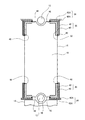
【解決手段】劣化したセメントアスファルトモルタル18を軌道スラブ14の周囲から水平方向の適宜深さまで除去することにより劣化した充填材の除去範囲32を形成し、該劣化した充填材の除去範囲32を塞ぐためのプラスチック段ボール40を対向配置し、該プラスチック段ボール40を外側から押え部材42で保持し、該押え部材42の上縁から下方に切り開いた窓部に該プラスチック段ボール40を臨ませ、該窓部に臨む該プラスチック段ボール40の部分を上縁から入れた切込みによって外側へ押し広げることにより、注入口を形成するように補修方法を構成する。
【選択図】図1In a method for repairing deterioration of a cement asphalt mortar layer of a slab track fixed with cement asphalt mortar sandwiched on a roadbed, it is possible to reduce the weight of the bottom formwork and make it easier to move and install, and to deteriorate the finish. Provide a repair method that can prevent and eliminate the use of disposable materials.
By removing a deteriorated cement asphalt mortar 18 from the periphery of the track slab 14 to a suitable depth in the horizontal direction, a deteriorated filler removal range 32 is formed, and the deteriorated filler removal range 32 is blocked. The plastic cardboard 40 is disposed opposite to the plastic cardboard 40, the plastic cardboard 40 is held by a pressing member 42 from the outside, and the plastic cardboard 40 is exposed to a window portion cut downward from the upper edge of the pressing member 42. The repairing method is configured to form the injection port by expanding the portion of the plastic corrugated cardboard 40 facing to the outside by a cut made from the upper edge.
[Selection] Figure 1
Description
この発明は、コンクリート構造物の路盤上にセメントアスファルトモルタルを挟んで軌道スラブを固定し、この軌道スラブに軌道レールを保持したスラブ式軌道において、セメントアスファルトモルタルが劣化によって割れ、剥離、脱落するのを補修するスラブ式軌道における補修方法に関するものである。 In this invention, a track slab is fixed on a roadbed of a concrete structure with a cement asphalt mortar sandwiched between the track slabs. It is related with the repair method in the slab type track | orbit which repairs.
コンクリートで構築した高架建造物とか、地下構造物や橋梁などを路盤とし、このコンクリート路盤上にセメントアスファルトモルタルを挟んでコンクリート製の軌道スラブを固定し、この軌道スラブに軌道レールを直結した構造のスラブ式軌道が広く採用されている。 The structure is such that an elevated structure constructed of concrete, an underground structure or a bridge is used as a roadbed, a concrete track slab is fixed on this concrete roadbed with cement asphalt mortar, and the track rail is directly connected to this track slab. Slab type track is widely adopted.
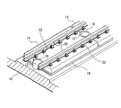
図9はスラブ式軌道の構造を一部断面して示す斜視図である。この図9において符号10はコンクリート路盤であり、この路盤10の上面には、レール敷設方向に沿って所定間隔(例えば5m間隔)ごとに円柱形の突起12が突出している。符号14は軌道スラブであり、これら軌道スラブ14の端部に形成した半円形の切欠き部16を前記突起12に位置合わせしながら順次並べられる。そしてこの軌道スラブ14を専用の器具で持ち上げ位置調整した後、路盤10と軌道スラブ14との間にセメントアスファルトモルタル(以下CAモルタルともいう)を注入充填し充填層18とするものである。
FIG. 9 is a perspective view showing a part of the structure of the slab type track. In FIG. 9,
CAモルタルは、セメントとアスファルト乳剤と、細骨材とを混合したものである。このCAモルタルは、路盤10の突起12と軌道スラブ14の切欠き部16との間にも充填されている。軌道スラブ14の上面には軌道レール20が締結具22により固定される。左右の軌道レール20は1つの軌道スラブ14に対しそれぞれ8個ずつの締結具22で固定される。
CA mortar is a mixture of cement, asphalt emulsion, and fine aggregate. The CA mortar is also filled between the
充填層18には、軌道レール20の温度変化による伸縮応力が軌道スラブ14を介して加わり、列車の通過や遠心力による外力が軌道スラブ14を介して加わる。このため充填層18の劣化・疲労が進む。また寒冷地では充填層18にしみ込んだ水が凍結・融解するため、その繰り返しにより充填層18は劣化が進み、その周辺の露出部分から割れや剥離や脱落が発生する。このため比較的短期間のうちに充填層18の補修が必要になる。
Stretching stress due to temperature change of the
特許文献1には、軌道スラブの側面から斜め下方に、軌道スラブと填充層を貫通し路盤コンクリートに至る孔(モルタル注入口、空気抜き口)を形成し、この孔から二液室温硬化型ラジカル重合性樹脂を注入する補修方法が示されている。この方法は軌道スラブ下方の填充層の全面に渡って補修材を流入させるものであり、硬化した補修材は孔に係合しているので軌道スラブの外側へ飛び出すのは防止できると思われる。 In Patent Document 1, a hole (mortar inlet, air vent) that penetrates the track slab and the filler layer and reaches the roadbed concrete is formed obliquely downward from the side surface of the track slab. A repair method for injecting a functional resin is shown. In this method, the repair material is caused to flow over the entire surface of the filling layer below the track slab, and since the hardened repair material is engaged with the hole, it is considered that it is possible to prevent the repair material from jumping out of the track slab.
特許文献2には、劣化した充填材を削り取った後、軌道スラブの側面(外周面)を木製あるいはアルミ製の型枠で囲み、この型枠と軌道スラブとの間に剥離シート(ポリエチレンシートなど)を介在させる方法が示されている。この場合に型枠の一部に設けた上方に向かって開く切欠きに剥離シートを押し広げ、剥離シートと軌道スラブ側面との間に補修用充填材を注入するものである。 In Patent Document 2, after scraping off the deteriorated filler, the side surface (outer peripheral surface) of the track slab is surrounded by a wooden or aluminum mold, and a release sheet (polyethylene sheet or the like) is formed between the mold and the track slab. ) Is shown. In this case, the release sheet is spread out in a notch opened upward in a part of the mold, and a repair filler is injected between the release sheet and the side surface of the track slab.
しかし引用文献1に示された方法では軌道スラブ下にできる隙間と孔の位置とが必ずしも対応していないから、充填材を隙間に正確に注入できるわけではない。また軌道スラブに側面から斜め下方に孔を形成するため、軌道スラブの強度低下を招くおそれがあり、孔の加工作業が面倒でもある。 However, in the method shown in the cited document 1, the gap formed under the track slab and the position of the hole do not necessarily correspond to each other, so that the filler cannot be accurately injected into the gap. Further, since the hole is formed in the track slab obliquely downward from the side surface, the strength of the track slab may be reduced, and the hole processing is troublesome.
特許文献2に示された方法では、型枠は1枚の軌道スラブの全長(5m)を一度に仕上げるため、1本の通し型枠とする必要がある。このため型枠が長く、重くなり、移動や設置に非常に大きな労力を必要とする。またこの型枠は新しく製作する頻度は少なく、通常使い回ししているため、経時的に反りや変形が発生し、樹脂等の硬化物が付着していることが多い。このため仕上がり精度が悪くなり、見栄えも悪くなる。 In the method disclosed in Patent Document 2, it is necessary to form a single formwork in order to finish the entire length (5 m) of one track slab at a time. For this reason, a formwork becomes long and heavy, and a very big effort is required for movement and installation. In addition, since this mold is rarely manufactured frequently and is usually reused, warping and deformation occur over time, and a cured product such as resin is often attached. For this reason, finishing accuracy is deteriorated and appearance is also deteriorated.
さらに剥離シートは充填材型枠に付着するのを防ぐために使うものであるが、シート状であるためにシワが発生し易く、充填材の仕上がり表面にこのシワの模様が付いてしまい見栄えが悪いという問題がある。またこの剥離シートは使い回しができず、一度使うと廃棄しなければならないので資源の有効利用の点でも問題があった。 Furthermore, the release sheet is used to prevent it from adhering to the filler formwork, but it is easy to generate wrinkles because it is in the form of a sheet, and this wrinkle pattern is attached to the finished surface of the filler, which makes it look bad. There is a problem. In addition, this release sheet cannot be reused, and once used, it must be discarded, so there is a problem in terms of effective use of resources.
この発明はこのような事情に鑑みなされたものであり、軌道スラブに孔を加工することによる軌道スラブの強度低下を招くおそれがなく、型枠を軽量化して移動、設置作業を容易にでき、型枠の変形や剥離シートのシワなどによる仕上がりの悪化を防ぐことができ、さらに剥離シートのような使い捨てにする資材もなくなる補修方法を提供することを目的とする。 The present invention has been made in view of such circumstances, there is no risk of reducing the strength of the track slab by processing a hole in the track slab, the mold can be reduced in weight, and can be easily moved and installed. It is an object of the present invention to provide a repair method that can prevent deterioration of the finish due to deformation of a mold or wrinkles of a release sheet, and further eliminates disposable materials such as a release sheet.
この発明によればこの目的は、コンクリート路盤にセメントアスファルトモルタルを挟んで軌道スラブを固定し、前記軌道スラブに軌道レールを保持したスラブ式軌道における補修方法において、(a)劣化した前記セメントアスファルトモルタルを前記軌道スラブの周囲から水平方向の適宜深さまで除去することにより空隙を形成する:(b)前記軌道スラブの外周から前記空隙を塞ぐようにプラスチック段ボールを対向配置し、(c)前記プラスチック段ボールを外側から押え部材で保持すると共に、この押え部材の上縁から下方に切り開いた窓部に前記プラスチック段ボールの一部を臨ませ、(d)前記プラスチック段ボールの前記窓部に臨む部分を上縁から入れた切込みによって外側へ押し広げることにより、軌道スラブ側面との間に上方に向かって開く注入口を形成し、(e)前記注入口から前記空隙に、補修用充填材を注入し、注入後に前記注入口を閉じて養生硬化し、(f)前記補修用充填材の硬化後に前記押え部材およびプラスチック段ボールを取外す、以上の工程a〜fの工程を順に行うことを特徴とするスラブ式軌道における補修方法、により達成される。 According to the present invention, this object is to provide a repair method for a slab type track in which a track slab is fixed to a concrete roadbed with a cement asphalt mortar and a track rail is held on the track slab. (A) The deteriorated cement asphalt mortar Is removed from the periphery of the track slab to an appropriate depth in the horizontal direction: (b) plastic cardboards are arranged opposite to each other so as to close the gap from the outer periphery of the track slab, and (c) the plastic cardboard Is held by a pressing member from the outside, and a part of the plastic corrugated cardboard is exposed to a window part cut downward from the upper edge of the pressing member, and (d) a part of the plastic corrugated cardboard facing the window part is an upper edge. Between the sides of the track slab by pushing outwards with a cut made from Forming an injection port that opens upward; (e) injecting a repair filler into the gap from the injection port; and closing and curing the injection port after the injection; and (f) the repair filler. This is achieved by a repair method for a slab type track in which the steps a to f are sequentially performed after the pressing member and the plastic cardboard are removed after curing.
型枠はプラスチック段ボール(プラスチックファイバー板箱、プラダン、プラ段、ダンプラ、段プラなどとも言う。)の外側を押え部材で保持するものとしたので、プラスチック段ボールが極めて軽量でかつ適度な強度、剛性を有する特性を利用して押え部材はベニヤ板などの軽量な材料とすることができる。このため型枠全体の大幅な軽量化が可能である。 The mold is made of plastic corrugated cardboard (also called plastic fiber board box, plastic platen, plastic corrugated board, dumpler, corrugated plastic) that is held by a pressing member, so the plastic corrugated cardboard is extremely lightweight and has adequate strength and rigidity. The presser member can be made of a lightweight material such as a plywood board by utilizing the characteristics having the above. For this reason, the overall weight of the mold can be greatly reduced.
プラスチック段ボールは樹脂に対して離型性が良いので剥離シートを併用する必要がない。このため仕上がりをきれいにすることができると共に剥離シートのような廃棄物が発生せず資源の無駄がなくなる。 Since plastic corrugated cardboard has good releasability with respect to resin, it is not necessary to use a release sheet in combination. For this reason, the finish can be made clean, and waste such as a release sheet is not generated, and resources are not wasted.
プラスチック段ボールはプラスチック(主にポリプロピレン)製の段ボールに似た中空構造のシートであり、中芯の波型と平行方向を水平にして、すなわち軌道スラブ、コンクリート路盤と平行にして軌道スラブの外周に配置するのがよい(請求項2)。 Plastic corrugated cardboard is a sheet of hollow structure similar to corrugated cardboard made of plastic (mainly polypropylene), with the corrugation of the core in the horizontal direction, that is, parallel to the track slab and concrete roadbed, on the outer periphery of the track slab. It is good to arrange (Claim 2).
このようにするとプラスチック段ボールの下部を中芯の波型に沿って外側へ水平に折曲し易く、この折曲部の下面を弾性材(ウレタンスポンジなど)を介してコンクリート路盤に押圧するのに押え部材の押圧力が効率良く加わり都合が良い(請求項3)。 In this way, the lower part of the plastic cardboard can be easily bent horizontally along the core corrugation, and the lower surface of the bent part is pressed against the concrete roadbed via an elastic material (urethane sponge, etc.). The pressing force of the pressing member is efficiently applied for convenience (claim 3).
押え部材にはベニヤ板、例えば厚さ10mmのものが使用できる。プラスチック段ボール自身に十分な強度があるため、押え部材の強度を下げることができるから、その軽量化が図れる(請求項4)。 As the pressing member, a plywood plate having a thickness of 10 mm can be used. Since the plastic corrugated board itself has sufficient strength, the strength of the pressing member can be lowered, so that the weight can be reduced.
プラスチック段ボールは通常半透明であるから、外側から充填材の注入量を確認し易い(請求項5)。例えば注入口となる押え部材に形成した窓部から注入液の液面を目視できる。押え部材に上下方向に長いスリット状の開口、あるいは上下に分布する複数の開口、上縁から切り込んだスリット状の開口などを形成しておけば、液量の確認位置を自由に設定できる(請求項6)。 Since plastic corrugated cardboard is usually translucent, it is easy to check the amount of filler injected from the outside (Claim 5). For example, the liquid level of the injected liquid can be visually observed from a window portion formed in the holding member serving as the injection port. If the presser member is formed with a slit-like opening that is long in the vertical direction, or a plurality of openings that are distributed vertically, a slit-like opening that is cut from the upper edge, etc., the liquid volume confirmation position can be set freely (claim) Item 6).
補修用の充填材としてラジカル硬化性を有する合成樹脂を基材として用いれば、この基材は流動性に富み、路盤と軌道スラブと、これらの間に挟まれたセメントアスファルトモルタルの充填層との接着力が非常に強く湿潤時の接着力も十分大きい。このため充填層(CAモルタル)の劣化した部分を周囲から削り取る(除去する)場合に、削り取り深さを浅くして削り取り量を少なくしても補修した充填材が外側へ飛び出すことがない(請求項7)。 If a radically curable synthetic resin is used as a base material for repair, this base material is rich in fluidity, and is composed of a roadbed, a track slab, and a cement asphalt mortar packed layer sandwiched between them. The adhesive strength is very strong and the adhesive strength when wet is sufficiently large. For this reason, when the deteriorated portion of the filler layer (CA mortar) is scraped (removed) from the surroundings, the repaired filler does not jump out to the outside even if the scraping depth is reduced and the scraping amount is reduced. Item 7).
ラジカル硬化性を有する合成樹脂は、ポリエステルアクリレートを主成分とする合成樹脂が適する(請求項8)。このポリエステルアクリレートは、より具体的には、無溶剤型ビニルエステル樹脂や変性MMA(メチルメタアクリレート)が最適である。接着力が強く耐久性も向上するからである。ポリエステルアクリレートを主成分とする合成樹脂としてポリエステルアクリレートのみを用いてもよい。 A synthetic resin mainly composed of polyester acrylate is suitable as the synthetic resin having radical curability (claim 8). More specifically, the polyester acrylate is most preferably a solvent-free vinyl ester resin or modified MMA (methyl methacrylate). This is because the adhesive strength is strong and the durability is improved. Only a polyester acrylate may be used as a synthetic resin mainly composed of a polyester acrylate.
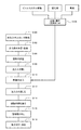
図1は本発明に係る補修方法の概念を示す平面図、図2は劣化した充填層の削り取り(除去)例を示す平面図、図3は削り取り作業例を示す図、図4は型枠の分解斜視図、図5は型枠の配置を示す断面図(A)と補修用充填材の注入口の断面図(B)、図6は作業工程図である。 1 is a plan view showing the concept of a repair method according to the present invention, FIG. 2 is a plan view showing an example of scraping (removing) a deteriorated packed bed, FIG. 3 is a diagram showing an example of scraping work, and FIG. FIG. 5 is an exploded perspective view, FIG. 5 is a cross-sectional view (A) showing the layout of the mold, a cross-sectional view (B) of the filling port for repairing material, and FIG.
図1においては前記図9と同一部分に同一符号を付した。硬化したCAモルタルからなる充填層18は外周から劣化が進むので、軌道スラブ14の外側から劣化した充填材を削り取る。図1で斜線部分32がこの劣化した充填材の除去範囲である。充填材の劣化は軌道スラブ14の四隅付近で特に進み易い。そこで図1ではこの四隅付近の充填材だけを除去するものとしている。なお劣化の進み具合を見て、四隅だけでなく両側面も十分深く除去したり、両側面は表面付近だけを浅く除去してもよい。
In FIG. 1, the same parts as those in FIG. Since the deterioration of the
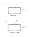
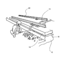
図2(A)の斜線部分は左右両側面も十分深く除去する場合の除去範囲32Aを示し、図2(B)の斜線部分は左右両側面を浅く除去する場合の除去範囲32Bを示す。除去範囲32(32A、32B)は軌道スラブ14の4隅付近で深く、隅以外で浅い。劣化充填材の削り取り(除去)作業は、図3に示すように行うことができる(図6のステップS100)。この図3は、作業者が先端に切削ビットを取付けた振動式削り機(ハツリ機)を用いて先端を充填層18を外側から削り取る(ハツリ)様子を示すものである。
The hatched portion in FIG. 2A shows the
削り量(ハツリ量)は、現場の劣化状況にあわせて決める。図2(A)は側面に沿って通常の深さ(100mm)に削り、隅付近をさらに深く削るものである。図2(B)は、4隅付近を通常より浅い深さ約50mmに削り、劣化の少ない側面を約10〜50mmの深さに削る。劣化した充填材(劣化CAモルタル)を削り取り除去した後にできる空隙34(図5参照)は補修用充填材の注入部となる。 The amount of shaving (the amount of chipping) is determined according to the on-site deterioration status. FIG. 2A shows a case where a normal depth (100 mm) is cut along the side surface, and a portion near the corner is cut deeper. In FIG. 2B, the vicinity of the four corners is cut to a depth of about 50 mm, which is shallower than usual, and the side surface with little deterioration is cut to a depth of about 10 to 50 mm. The gap 34 (see FIG. 5) formed after scraping and removing the deteriorated filler (deteriorated CA mortar) serves as an injection portion for the repair filler.
次にこの空隙(注入部)34を清掃し、ガスバーナーを用いて乾燥させる(ステップS102)。そして軌道スラブ14の側面に型枠36を当てて固定する(ステップS104)。この型枠36の設置に先立って、軌道スラブ14の側面に養生ガムテープ38を貼り付け、後記する補修用充填材が付着するのを防ぐ。
Next, this space | gap (injection part) 34 is cleaned, and it is made to dry using a gas burner (step S102). Then, the
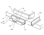
型枠36はプラスチック段ボール40と押え部材42で形成される。プラスチック段ボール40は全体がポリプロピレン製であり、波型の中芯をライナーで挟み接着したものである。厚さは3〜6mm程度で極めて軽量である。また表面(両面)は充填材が付着しにくく離型性が良い。さらに適度の強度、剛性を有する一方、ナイフなどで容易にカットしたり切れ目を入れたりでき加工性も良い。
The
このプラスチック段ボール40は補修用充填材を注入する空隙34の外側を囲むものであり、図4に示すように中芯の波型に沿って(すなわち波型の山、谷と平行な)長板状に切って使う。ここにプラスチック段ボール38の下部は外側に水平に折曲され、この折曲部44の下面には弾性材となるウレタンスポンジ46の薄板が接着されている。
The plastic
押え部材42は約10mm厚のベニヤ板の長板であり、プラスチック段ボール40の外側および折曲部42の上面に密着している。この押え部材42は適宜の押圧治具(図示せず)により所定位置に保持される。例えば軌道スラブ14の上面に固定されるレール20やその締結具22(図9参照)に固定した押圧治具や、軌道スラブ14の側面に通常形成されているインサートボルト穴に固定した押圧治具を用いる。この結果プラスチック段ボール40は上部が養生ガムテープ38に密着する。また下部の折曲部44がウレタンスポンジ46を介してコンクリート路盤10に押圧され、後記する充填材54の漏出が防止される。
The pressing
押え部材42は、図1に示す軌道スラブ14の四隅だけを補修する場合には、この四隅付近を囲む2辺の長さで足りる。なお隣接する軌道スラブ14との間隙にも同様にプラスチック段ボール40Aと押え部材42Aが挿入される(図1参照)。この押え部材42Aは省くことも可能であるが、これらは隣りの軌道スラブ14との間隙にくさびなど挿入することにより空隙34側に押圧する。なおプラスチック段ボール40,40Aの一端(空隙34の端側)と軌道スラブ14の側面(外周面)との間には、空隙34から充填材54が流出するのを防ぐためのシール材(ウレタンスポンジなど)46(図1)を挟んでおくのがよい。
In the case where only the four corners of the
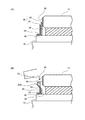
次に注入口48(図5の(B)参照)を説明する。押え部材42には図4,図5(B)に示すように、上縁から下方に切り開いた窓部50が形成されている。この窓部50にはプラスチック段ボール40が現れている(臨んでいる)。この窓部50に臨むプラスチック段ボール40には上縁からカッタナイフ(図示せず)などで縦に2本の切込み52が加工される(図4)。そして切込んだ部分40Aを窓部50側へ押し広げることにより注入口48が形成される(図6,ステップS106)。この切込み52は型枠36の組立て前に予め加工しておいてもよい。
Next, the inlet 48 (see FIG. 5B) will be described. As shown in FIGS. 4 and 5B, the pressing
このようにして型枠36の設置を行う一方、補修用の充填材54とするためにビニルエステル樹脂とその硬化剤と骨材とを混練し攪拌しておく(ステップS108)。ビニルエステル樹脂は、例えば出願人が販売する「アレンロックS」(商品名)が適する。この場合硬化剤としては、出願人が販売する「パーカドックスCH−50L」(商品名)が適する。骨材としては硅砂8号が適する。これらは重量比で、ビニルエステル樹脂と硬化剤と骨材の混合比が約100:3:100となるようにするのがよい。この場合には混練物である補修用充填材50は20℃で10〜15分で硬化する。この硬化時間(可使時間)を考慮して樹脂の準備と型枠36の設置とを併行して行う。
In this way, while the
一方型枠36には、プラスチック段ボール40の切込み部40Aを窓部50から外側へ押し広げ保持することによって、軌道スラブ14との間に上方に向かって開く注入口48を形成する(図5の(B)参照)。このように上方に開いた注入口48に前記のように予めまたは併行して混練しておいた補修用充填材54を注入する(ステップS110)。この時注入口48付近で流れ方向を案内しながら、補修用充填材54を空隙34に導く。また注入口48から、補修用充填材54が空隙34内の全体に亘って注入されていることを確認する。この時プラスチック段ボール40は半透明なのでこれを通して注入量を確認できる。
On the other hand, the
補修用充填材54が空隙34内の全体に流入したことを確認してから、切込み部40Aを元の直立位置に戻し、ガムテープなどで固定することによって注入口48を閉じる(ステップS112)。この状態で補修用充填材54が硬化するのを待つ(ステップS114)。この硬化した補修用充填材54は、図1に斜線で示した空隙32、32A、32Bを埋める。補修用充填材54の硬化を待って、型枠36を取外し(ステップS116)、周囲を清掃する(ステップS118)。
After confirming that the
なお図2の(A)、(B)のように、軌道スラブ14の左右両側面の全長に亘る除去範囲32A、32Bとした場合には、型枠36はこれらの除去範囲32A、32Bを覆うように軌道スラブ14の全長の長さにするのは勿論である。
As shown in FIGS. 2A and 2B, when the removal ranges 32A and 32B extend over the entire length of the left and right side surfaces of the
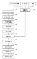
図7は本発明の他の実施例の作業工程図である。この実施例は、前記実施例1における工程S102とS104の間に次の工程、すなわち空隙(注入部)34の内面にプライマーを刷毛などで塗布する工程(S103)を加えたものである。 FIG. 7 is a work process diagram of another embodiment of the present invention. In this embodiment, the following step, that is, a step (S103) of applying a primer to the inner surface of the gap (injection portion) 34 with a brush or the like is added between steps S102 and S104 in the first embodiment.
ここに用いるプライマーとしてはウレタン樹脂、エポキシ樹脂、ラジカル硬化性を有する合成樹脂のいずれか、またはこれにセメント粉を混合したものが適する。なおこの場合補修用充填材は前記実施例1で用いたもの、すなわちビニルエステル樹脂とその硬化剤と骨材とを混練し攪拌したものである。以下の工程S104〜S118は前記実施例1と同じである。 As a primer used here, a urethane resin, an epoxy resin, a synthetic resin having radical curability, or a mixture of this with cement powder is suitable. In this case, the repair filler is the same as that used in Example 1, that is, the vinyl ester resin, its curing agent and aggregate are kneaded and stirred. The following steps S104 to S118 are the same as those in the first embodiment.
この実施例2によれば、補修用充填材54Aの接触面に予めプライマーが塗布されているので、充填材の注入後に雨が降ったり結露により空隙(注入部)34内面に水が付着していても、コンクリート路盤10および軌道スラブ14に塗布されたプライマーについた水は、比重の重い補修用充填材54Aで押しのけられてプライマーと一体化するため、補修用充填材54Aと空隙34の内面すなわちコンクリート路盤10および軌道スラブ14との結合強度が低下しない。このため補修した充填材が外側へ飛び出すおそれがない。
According to the second embodiment, since the primer is preliminarily applied to the contact surface of the repair filler 54A, water adheres to the inner surface of the gap (injection portion) 34 due to rain or condensation after the filler is injected. However, since the water applied to the primer applied to the
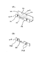
図8に示す実施例は、型枠36の押え部材42A、42Bを通して充填液54の注入量を外から目視により確認し易くしたものである。図8の(A)に示す実施例では、押え部材42Aの上縁から下向きに切り込んだ適宜数のスリット状の開口56を形成した。また図8の(B)に示す実施例では、押え部材42Bに上下方向に広がる縦長のスリット状開口56Aや、上下に分割して上下に分布する複数の開口56Bを設けた。図8(A)の開口54は加工性が良く、また図8(B)の開口54A、54Bによれば押え部材42Bの強度低下を防止できる。
The embodiment shown in FIG. 8 makes it easy to visually confirm the injection amount of the filling
10 路盤
14 軌道スラブ
18 充填層(セメントアスファルトモルタル)
20 軌道レール
22 締結具
32(32A、32B) 劣化した充填材の除去範囲
34 空隙
36 型枠
40 プラスチック段ボール
40A 切込み部
42、42A、42B 押え部材(ベニヤ板)
48 注入口
50 窓部
52 切込み
56、56A、56B スリット状開口(注入量確認用の開口)
10
20
48
Claims (8)
(a)劣化した前記セメントアスファルトモルタルを前記軌道スラブの周囲から水平方向の適宜深さまで除去することにより空隙を形成する:
(b)前記軌道スラブの外周から前記空隙を塞ぐようにプラスチック段ボールを対向配置し、
(c)前記プラスチック段ボールを外側から押え部材で保持すると共に、この押え部材の上縁から下方に切り開いた窓部に前記プラスチック段ボールの一部を臨ませ、
(d)前記プラスチック段ボールの前記窓部に臨む部分を上縁から入れた切込みによって外側へ押し広げることにより、軌道スラブ側面との間に上方に向かって開く注入口を形成し、
(e)前記注入口から前記空隙に、補修用充填材を注入し、注入後に前記注入口を閉じて養生硬化し、
(f)前記補修用充填材の硬化後に前記押え部材およびプラスチック段ボールを取外す、
以上の工程a〜fの工程を順に行うことを特徴とするスラブ式軌道における補修方法。 In the repair method in the slab type track where the track slab is fixed to the concrete roadbed with cement asphalt mortar and the track rail is held on the track slab,
(A) A void is formed by removing the deteriorated cement asphalt mortar from the periphery of the track slab to an appropriate depth in the horizontal direction:
(B) Placing plastic corrugated cardboard so as to close the gap from the outer periphery of the track slab,
(C) holding the plastic cardboard with a pressing member from the outside, and allowing a part of the plastic cardboard to face a window portion opened downward from the upper edge of the pressing member;
(D) forming an injection port that opens upward between the side surface of the track slab by spreading the portion of the plastic cardboard facing the window portion outward by a cut made from an upper edge;
(E) A repair filler is injected into the gap from the injection port, and after the injection, the injection port is closed and cured and cured.
(F) removing the pressing member and the plastic corrugated cardboard after the repair filler is cured;
The repair method in the slab type | formula track | truck characterized by performing the process of the above process af in order.
Priority Applications (1)
| Application Number | Priority Date | Filing Date | Title |
|---|---|---|---|
| JP2009223072A JP5430324B2 (en) | 2009-09-28 | 2009-09-28 | Repair method for slab type track |
Applications Claiming Priority (1)
| Application Number | Priority Date | Filing Date | Title |
|---|---|---|---|
| JP2009223072A JP5430324B2 (en) | 2009-09-28 | 2009-09-28 | Repair method for slab type track |
Publications (2)
| Publication Number | Publication Date |
|---|---|
| JP2011069167A true JP2011069167A (en) | 2011-04-07 |
| JP5430324B2 JP5430324B2 (en) | 2014-02-26 |
Family
ID=44014679
Family Applications (1)
| Application Number | Title | Priority Date | Filing Date |
|---|---|---|---|
| JP2009223072A Expired - Fee Related JP5430324B2 (en) | 2009-09-28 | 2009-09-28 | Repair method for slab type track |
Country Status (1)
| Country | Link |
|---|---|
| JP (1) | JP5430324B2 (en) |
Cited By (3)
| Publication number | Priority date | Publication date | Assignee | Title |
|---|---|---|---|---|
| JP2015168969A (en) * | 2014-03-06 | 2015-09-28 | 株式会社アレン | Form for repairing slab type track, and construction method for repairing filling layer of slab type track |
| JP2020041397A (en) * | 2018-09-07 | 2020-03-19 | 株式会社アレン | Repair molding box for slab track and method of repairing filling layer of slab track using the same |
| JP2025067680A (en) * | 2023-10-13 | 2025-04-24 | 株式会社アレン | Repair form for slab-type track and filling repair method for slab-type track using the same |
Citations (3)
| Publication number | Priority date | Publication date | Assignee | Title |
|---|---|---|---|---|
| JPH0165301U (en) * | 1987-10-16 | 1989-04-26 | ||
| JPH11256504A (en) * | 1998-03-16 | 1999-09-21 | East Japan Railway Co | Repair material and repair method for slab track |
| JP2008057318A (en) * | 2006-08-04 | 2008-03-13 | Aren:Kk | Repair method for slab type track |
-
2009
- 2009-09-28 JP JP2009223072A patent/JP5430324B2/en not_active Expired - Fee Related
Patent Citations (3)
| Publication number | Priority date | Publication date | Assignee | Title |
|---|---|---|---|---|
| JPH0165301U (en) * | 1987-10-16 | 1989-04-26 | ||
| JPH11256504A (en) * | 1998-03-16 | 1999-09-21 | East Japan Railway Co | Repair material and repair method for slab track |
| JP2008057318A (en) * | 2006-08-04 | 2008-03-13 | Aren:Kk | Repair method for slab type track |
Cited By (4)
| Publication number | Priority date | Publication date | Assignee | Title |
|---|---|---|---|---|
| JP2015168969A (en) * | 2014-03-06 | 2015-09-28 | 株式会社アレン | Form for repairing slab type track, and construction method for repairing filling layer of slab type track |
| JP2020041397A (en) * | 2018-09-07 | 2020-03-19 | 株式会社アレン | Repair molding box for slab track and method of repairing filling layer of slab track using the same |
| JP7367953B2 (en) | 2018-09-07 | 2023-10-24 | 株式会社アレン | Repair formwork for slab type track and filling layer repair method for slab type track using the same |
| JP2025067680A (en) * | 2023-10-13 | 2025-04-24 | 株式会社アレン | Repair form for slab-type track and filling repair method for slab-type track using the same |
Also Published As
| Publication number | Publication date |
|---|---|
| JP5430324B2 (en) | 2014-02-26 |
Similar Documents
| Publication | Publication Date | Title |
|---|---|---|
| JP4897607B2 (en) | Repair method for slab type track | |
| US8888067B1 (en) | Thermoplastic liner for casting textures and objects into poured wall | |
| US20140069050A1 (en) | Composite panels and methods and apparatus for manufacture and installtion thereof | |
| JP5430324B2 (en) | Repair method for slab type track | |
| JP6592297B2 (en) | Slab track repair structure, adhesive sheet used for slab track repair structure, and slab track repair method | |
| JP5430356B2 (en) | Repair method for slab type track | |
| JP7367953B2 (en) | Repair formwork for slab type track and filling layer repair method for slab type track using the same | |
| JP4364937B1 (en) | Concrete jointing joint material and waterproof construction method | |
| KR200418048Y1 (en) | Eurofoam plywood protective film | |
| CN100473795C (en) | Thermoplastic resin form | |
| JP4875881B2 (en) | Noro stop | |
| JP2016029252A (en) | Slab track repair structure and slab track repair method | |
| JP4932639B2 (en) | Concrete specimen collection container | |
| JP4995945B2 (en) | Repair method for concrete floor slab edge bottom surface | |
| JP2004270406A (en) | Embedded material for concrete slab | |
| JP2977511B2 (en) | Method of recycling concrete formwork and its recycled concrete formwork | |
| JP2001295207A (en) | How to repair holes in synthetic wood | |
| JPH10292624A (en) | Rugged pattern with three-dimensional curve, three-dimensional decorative concrete form with holding device embedded to hold concrete side pressure, and forming method thereof | |
| RU2812987C1 (en) | Method for manufacturing wall panel with facing covering decoration and device for its implementation | |
| JPH0216685B2 (en) | ||
| KR102913424B1 (en) | Manufacturing method for multifunctional sheet | |
| JPH0533483A (en) | Form | |
| KR100772323B1 (en) | Forming plate method for reinforcement and repair of concrete structures | |
| JP4676391B2 (en) | Slope reinforcement method using wooden formwork | |
| KR200229799Y1 (en) | resinous form with pattern |
Legal Events
| Date | Code | Title | Description |
|---|---|---|---|
| A621 | Written request for application examination |
Free format text: JAPANESE INTERMEDIATE CODE: A621 Effective date: 20120906 |
|
| A977 | Report on retrieval |
Free format text: JAPANESE INTERMEDIATE CODE: A971007 Effective date: 20130625 |
|
| TRDD | Decision of grant or rejection written | ||
| A01 | Written decision to grant a patent or to grant a registration (utility model) |
Free format text: JAPANESE INTERMEDIATE CODE: A01 Effective date: 20131105 |
|
| A61 | First payment of annual fees (during grant procedure) |
Free format text: JAPANESE INTERMEDIATE CODE: A61 Effective date: 20131203 |
|
| R150 | Certificate of patent or registration of utility model |
Free format text: JAPANESE INTERMEDIATE CODE: R150 Ref document number: 5430324 Country of ref document: JP Free format text: JAPANESE INTERMEDIATE CODE: R150 |
|
| R250 | Receipt of annual fees |
Free format text: JAPANESE INTERMEDIATE CODE: R250 |
|
| R250 | Receipt of annual fees |
Free format text: JAPANESE INTERMEDIATE CODE: R250 |
|
| R250 | Receipt of annual fees |
Free format text: JAPANESE INTERMEDIATE CODE: R250 |
|
| R250 | Receipt of annual fees |
Free format text: JAPANESE INTERMEDIATE CODE: R250 |
|
| R250 | Receipt of annual fees |
Free format text: JAPANESE INTERMEDIATE CODE: R250 |
|
| R250 | Receipt of annual fees |
Free format text: JAPANESE INTERMEDIATE CODE: R250 |
|
| R250 | Receipt of annual fees |
Free format text: JAPANESE INTERMEDIATE CODE: R250 |
|
| R250 | Receipt of annual fees |
Free format text: JAPANESE INTERMEDIATE CODE: R250 |
|
| LAPS | Cancellation because of no payment of annual fees |