JP2011051027A - Connecting flange - Google Patents
Connecting flange Download PDFInfo
- Publication number
- JP2011051027A JP2011051027A JP2009199286A JP2009199286A JP2011051027A JP 2011051027 A JP2011051027 A JP 2011051027A JP 2009199286 A JP2009199286 A JP 2009199286A JP 2009199286 A JP2009199286 A JP 2009199286A JP 2011051027 A JP2011051027 A JP 2011051027A
- Authority
- JP
- Japan
- Prior art keywords
- frame
- groove
- flow path
- motor
- connecting flange
- Prior art date
- Legal status (The legal status is an assumption and is not a legal conclusion. Google has not performed a legal analysis and makes no representation as to the accuracy of the status listed.)
- Pending
Links
Images


Abstract
Description
本発明は、工作機械におけるスピンドルを回動可能に支持するフレームと、そのスピンドルにカップリングを介して連結される駆動軸を有するモーターとの連結に用いられる連結フランジに関し、詳しくは、モーターの熱がフレームへ伝達されること等を防止する連結フランジに関する。 The present invention relates to a connection flange used for connection between a frame that rotatably supports a spindle in a machine tool and a motor having a drive shaft that is connected to the spindle via a coupling. It is related with the connection flange which prevents that a flame | frame is transmitted to a flame | frame.
平面研削盤等の工作機械においては、X軸方向に往復動する加工テーブル上にワークを載置した状態で、Y軸方向に往復動するコラムに装着されZ軸方向に往復動するサドルにスピンドルを回転自在に支持すると共に、そのスピンドルの先端部に砥石を装着している。そして、スピンドル及び砥石を回転させて加工テーブル上のワークを研削加工する。又、サドルにはフレームが取り付けられて、そのフレームに円筒状のクイルが挿入固定されている。そのクイルの内部にはスピンドルがベアリングを介して支持されている。このスピンドルの砥石が支持される側とは反対の基端部には、モーターの駆動軸がカップリングを介して連結されている。 In a machine tool such as a surface grinding machine, a spindle is mounted on a saddle that is mounted on a column that reciprocates in the Y-axis direction and reciprocates in the Z-axis direction while a workpiece is placed on a machining table that reciprocates in the X-axis direction. And a grindstone is attached to the tip of the spindle. Then, the workpiece on the processing table is ground by rotating the spindle and the grindstone. A frame is attached to the saddle, and a cylindrical quill is inserted and fixed to the frame. A spindle is supported inside the quill via a bearing. A drive shaft of a motor is connected to a base end portion of the spindle opposite to the side on which the grindstone is supported via a coupling.
機械の作動時には、スピンドルの高速回転に伴いベアリングが発熱し、その熱がクイルに伝達され、さらにフレームに伝達されてフレームの温度を高める。ところが、一般に、上記のようなスピンドルの支持構造においては、フレームの上側部と下側部とのそれぞれの構造及び質量が異なる。すると、フレームの下側部と上側部とでは熱膨張量が異なり、フレームが全体として下側部と上側部とのいずれかの側に僅かに反る。このため、クイル及びスピンドルが基準線(例えば水平線)に対し、僅かではあるが傾斜することになる。このスピンドルの傾斜により砥石の回転軸線が偏心するので、ワークの研削面の精度が低下するという問題があった。 During the operation of the machine, the bearing generates heat as the spindle rotates at a high speed, and the heat is transmitted to the quill and further transmitted to the frame to raise the temperature of the frame. However, in general, in the spindle support structure as described above, the structures and masses of the upper and lower parts of the frame are different. Then, the amount of thermal expansion differs between the lower side portion and the upper side portion of the frame, and the frame slightly warps to one of the lower side portion and the upper side portion as a whole. For this reason, the quill and the spindle are slightly inclined with respect to a reference line (for example, a horizontal line). Since the rotation axis of the grindstone is decentered due to the inclination of the spindle, there is a problem in that the accuracy of the grinding surface of the workpiece is lowered.
特許文献1に開示されている「工作機械におけるスピンドルの支持構造」では、フレームに円筒状のクイルを嵌入固定し、そのクイルの内部にベアリングを介してスピンドルを支持すると共に、スピンドルに砥石を取り付けている。クイルの外周面とフレームの内側面との間には、冷却オイルの流通を許容する空間が形成されている。この空間に外部から冷却オイルを供給して、クイル及びフレームの温度が、伝達されたベアリングの熱により上昇することを抑制している。このため、フレームの不均一な熱膨張は抑制され、スピンドルの回転精度を高め、加工具によるワークの加工精度を向上することができるようになっている。
In the “support structure of spindle in machine tool” disclosed in
近年、精密機械加工においては、極めて高いレベルの加工精度が求められている。特許文献1の支持構造によれば、クイルとフレームとの間の空間に冷却オイルが供給されることにより、クイルとフレームとの昇温を抑制するようになっているが、フレームのあらゆる部位が一様に冷却されるようにはなっていない。また、フレームの温度を上昇させるものとしては、クイルを介して伝達される熱の他に、取付部を介してモーターから伝達される熱がある。このため、フレーム全体としての歪みは、高レベルの加工精度が求められる精密機械加工における支持構造としては、無視し得ない問題である。
In recent years, a very high level of machining accuracy is required in precision machining. According to the support structure of
本発明は、このような問題に着目してなされたものであり、その目的とするところは、スピンドルの回転精度を高め、加工具によるワークの加工精度を向上させるために、モーターとモーターが取り付けられるフレームとの間で挟持され、モーターからフレームへの熱の伝達を阻止する連結フランジを提供することにある。 The present invention has been made paying attention to such problems, and the object of the present invention is to attach a motor and a motor in order to increase the rotation accuracy of the spindle and improve the processing accuracy of the workpiece by the processing tool. Another object of the present invention is to provide a connecting flange that is sandwiched between a frame and a motor to prevent heat transfer from the motor to the frame.
上記問題を解決するために請求項1に記載の連結フランジの発明は、先端に工具を装着したスピンドルを回動可能に支持するフレームと、前記スピンドルにカップリングを介して連結される駆動軸を有するモーターとの連結において、前記フレームの取付部と前記モーターのフランジ部との間に挟持され、冷却用流体の流通を許容する流路が形成されていることを特徴とするものである。
In order to solve the above-mentioned problem, the invention of the connecting flange according to
上記構成によれば、流路を流れる冷却用流体により、モーターのフランジ部から伝達される熱を奪うようにした。このため、モーターのフランジ部からフレームへの熱伝達が阻止されるので、フレームの温度を上昇させる熱を、クイル等を介して伝達されるベアリングの熱に限定することができる。従って、熱膨張による歪の発生を阻止するために、フレームの温度調節を行うことが容易となる。 According to the above configuration, the heat transferred from the flange portion of the motor is taken away by the cooling fluid flowing through the flow path. For this reason, since heat transfer from the flange portion of the motor to the frame is prevented, the heat for raising the temperature of the frame can be limited to the heat of the bearing transmitted through the quill or the like. Therefore, it becomes easy to adjust the temperature of the frame in order to prevent the occurrence of distortion due to thermal expansion.
請求項2に記載の発明は、請求項1に記載の連結フランジにおいて、前記流路は、前記駆動軸に直交する方向に配置される平面部に形成された溝であることを特徴とするものである。 According to a second aspect of the present invention, in the connecting flange according to the first aspect, the flow path is a groove formed in a flat portion arranged in a direction orthogonal to the drive shaft. It is.
上記構成によれば、モーターの駆動軸に直交する方向に配置される平面部に溝を形成し、その溝を流路とした。このため、連結フランジの端部の複数ヶ所からドリルにより孔を穿孔し、それぞれの孔の一部が交錯するようにして、流路を形成する場合と異なり、任意の形状の流路を容易に形成することができる。 According to the said structure, the groove | channel was formed in the plane part arrange | positioned in the direction orthogonal to the drive shaft of a motor, and the groove | channel was made into the flow path. For this reason, unlike the case of forming a flow path by drilling holes from a plurality of locations at the end of the connection flange and crossing a part of each hole, a flow path of any shape can be easily formed. Can be formed.
請求項3に記載の発明は、請求項2に記載の連結フランジにおいて、前記流路は、前記平面部において、複数の屈曲点又は変曲点によって連結した複数の直線状又は曲線状の溝であることを特徴とするものである。
The invention according to
上記構成によれば、複数の直線状又は曲線状の溝を、複数の屈曲点又は変曲点によって連結して、流路をより長くするようにした。このため、連結フランジに供給されて排出されるまでの間に冷却用流体が連結フランジに接する面積が増えたので、冷却用流体は、モーターから伝達された熱をより多く奪うことができる。 According to the above configuration, a plurality of linear or curved grooves are connected by a plurality of bending points or inflection points to make the flow path longer. For this reason, since the area where the cooling fluid contacts the connection flange increases until the cooling fluid is supplied to the connection flange and discharged, the cooling fluid can take more heat transferred from the motor.
請求項4に記載の発明は、請求項2又は3に記載の連結フランジにおいて、前記流路は、前記平面部における基準円の内側と外側とに交互に位置を変える蛇行状に配置された溝であることを特徴とするものである。 According to a fourth aspect of the present invention, there is provided the connecting flange according to the second or third aspect, wherein the flow path is arranged in a meandering manner in which the position of the flow path is alternately changed between an inner side and an outer side of a reference circle. It is characterized by being.
上記構成によれば、流路としての溝を、基準円の内側と外側とに交互に位置を変える蛇行状に配置した。このため、流路が広範囲に亘ると共に、冷却用流体が流路をスムーズに流れることができるので、連結フランジの冷却を効率的に行うことができる。 According to the said structure, the groove | channel as a flow path was arrange | positioned in the meandering form which changes a position alternately to the inner side and the outer side of a reference | standard circle. For this reason, since the flow path covers a wide range and the cooling fluid can flow smoothly through the flow path, the connection flange can be efficiently cooled.
請求項5に記載の発明は、請求項2ないし4のうちいずれか一項に記載の連結フランジにおいて、前記溝は、エンドミルにより一筆書き状に連続して形成されたことを特徴とするものである。 A fifth aspect of the present invention is the connecting flange according to any one of the second to fourth aspects, wherein the groove is continuously formed in a single stroke by an end mill. is there.
上記構成によれば、エンドミルを用いて溝を一筆書き状に連続して形成した。このため、流路の途中に冷却用流体が行き止まりとなる部分の形成を未然に防止することができる。従って、温度調節された冷却用流体を連結フランジの冷却に効率よく用いることができる。また、その行き止まり部分に冷却用流体が流れ込まないように、堰き止めとして、例えばボスを打ち込む等の煩雑な作業を省くことができる。 According to the said structure, the groove | channel was continuously formed in the stroke shape using the end mill. For this reason, it is possible to prevent the formation of a portion where the cooling fluid stops in the middle of the flow path. Therefore, the temperature-controlled cooling fluid can be efficiently used for cooling the connecting flange. Moreover, as a damming stop, for example, a troublesome operation such as driving a boss can be omitted so that the cooling fluid does not flow into the dead end portion.
請求項6に記載の発明は、請求項2ないし5のうちいずれか一項に記載の連結フランジにおいて、板状の一面に前記溝が形成された基体と、その基体の前記一面を覆う副体とより構成されることを特徴とするものである。 According to a sixth aspect of the present invention, in the connecting flange according to any one of the second to fifth aspects, the base body in which the groove is formed on one plate-like surface and the sub-body that covers the one surface of the base body It is characterized by comprising.
上記構成によれば、基体と、その基体の溝が形成された面を覆う副体とにより、内部に流路を有する連結フランジを形成した。このため、このため、基体の溝が形成された面と、モーターのフランジ部又はフレームの取付部とを合わせて流路を形成する場合のように、フランジ部又は取付部において、液状シール剤を用いるために面粗度を上げるための仕上げ加工や、ガスケット等のシール材を配置するための溝加工等を省くことができる。 According to the said structure, the connection flange which has a flow path inside was formed by the base | substrate and the subbody which covers the surface in which the groove | channel of the base | substrate was formed. For this reason, the liquid sealant is applied to the flange portion or the attachment portion as in the case where the flow path is formed by combining the grooved surface of the base with the flange portion of the motor or the attachment portion of the frame. Therefore, it is possible to omit finishing processing for increasing the surface roughness and groove processing for arranging a sealing material such as a gasket.
本発明によれば、連結フランジの流路を流れる冷却用流体により、モーターのフランジ部から伝達される熱を奪うようにした。このため、モーターのフランジ部からフレームへの熱伝達が阻止されるので、フレームの温度を上昇させる熱を、クイルを介して伝達されるベアリングの熱に限定することができ、フレームの温度調節を行うことが容易となる。従って、スピンドルの回転精度を高め、加工具によるワークの加工精度を向上させることができる。 According to the present invention, the heat transferred from the flange portion of the motor is taken away by the cooling fluid flowing through the flow path of the connecting flange. For this reason, heat transfer from the motor flange to the frame is prevented, so the heat that raises the temperature of the frame can be limited to the heat of the bearing transmitted through the quill, and the temperature control of the frame Easy to do. Therefore, the rotational accuracy of the spindle can be increased, and the processing accuracy of the workpiece by the processing tool can be improved.
(第1の実施形態)
以下、本発明を具体化した第1実施形態を図1〜図3を用いて説明し、その別例を図4及び図5を用いて説明する。
(First embodiment)
Hereinafter, a first embodiment embodying the present invention will be described with reference to FIGS. 1 to 3, and another example will be described with reference to FIGS. 4 and 5.
先ず、本実施形態の連結フランジ10を挟持するフレーム2とモーター1との配置及び構造の一部を説明する。図1に示すように、Z軸方向に往復動可能に支持されているサドル(図示せず)に取り付けられたフレーム2には、円筒状のクイル4が嵌入固定されている。そのクイル4の内部には、スピンドル3がラジアルベアリング5とスラストベアリング6とにより回転自在に支持されている。スラストベアリング6は、図示しないボルトによりクイル4に固定されるホルダー7により支持されている。そして、スピンドル3とモーター1の駆動軸9とはカップリング8により連結されている。
First, the arrangement and part of the structure of the
駆動軸9を有するモーター1のフランジ部13には、駆動軸9の軸心と同心の環状の凸部14が形成され、その凸部14は、連結フランジ10を構成する基体10aと副体10bとのうちの一方の基体10aの凹部15に嵌合している。また、基体10aの凹部15が形成されている面とは反対側の面には、凹部15と同心の環状の凸部16が形成され、フレーム2の凹部17に嵌合している。また、フレーム2の取付部19に対向するように副体10bが配置されている。副体10bは、中心部の孔が凸部16に外嵌している。
The
そして、取付部19に形成された図示しないねじ孔に螺合される同じく図示しないボルトにより、連結フランジ10は、取付部19とフランジ部13との間に挟持されている。この時、基体10aに形成された断面角状の溝11は、副体10bにより覆われて、後述する形状の流路を形成する。基体10a及び副体10bの材質については特に限定しないが、これらの両方又はいずれか一方は、熱の伝導性に優れた金属、例えば、アルミ合金、青銅、黄銅等を用いることが好ましい。
The connecting
なお、基体10aと副体10bとの間には、液状シール剤或いはガスケット等のシール材を設け、溝11を流れる冷却用流体が漏出しないようにしている。本実施形態では、図2において二点差線で示すシール位置24に対応するように、基体10aに対向する副体10bの面にガスケット用の溝(図示せず)を設け、ガスケットを装着している。また、基体10aの凸部16にも、図示しないガスケットを装着している。
A sealing material such as a liquid sealant or a gasket is provided between the
図2に示すように、基体10aは四角板状体であり、4ヶ所の隅角にはボルト用孔27が形成されている。なお、図示しないが、副体10bの外形状も基体10aと同一にされ、同一配置のボルト用孔27が形成されている。
As shown in FIG. 2, the
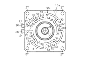
そして、冷却用流体の流路としての溝11は、駆動軸9と同心となる基準円23の内側と外側とに交互に位置を変える蛇行状に、内側に向かって凸の曲線状溝11aと外側に向かって凸の曲線状溝11bとが変曲点11cで連結して形成されている。このように溝11を一筆書き状に形成するためには、エンドミルによる加工が好ましく、更にはNCによるエンドミル加工が好ましい。
The groove 11 serving as a cooling fluid flow path is a meandering
なお、基準円23の大きさは特に限定されるものではなく任意とすることができる。また、本実施形態では、変曲点11cが略基準円23上となっているが、基準円23の内側でも外側でも配置することは可能である。更に、本実施形態では、曲線状溝11bの数を7個としているが、6個以下であっても、8個以上であってもよい。冷却用流体による冷却効率の点から、基準円23の大きさ、変曲点11cの位置、曲線状溝11bの数等を選択することが好ましい。
In addition, the magnitude | size of the reference |
図2及び図3に示すように、基体10aの側面には、図示しない冷却用流体の温度調節部に配管により連結される供給連結部21と排出連結部22とが設けられている。供給連結部21に形成された連通穴26と、その連通穴26に対して直交する方向に形成された連通穴25とを介して、冷却用流体が溝11へ供給される。そして、排出連結部22に形成された連通穴26と、その連通穴26に対して直交する方向に形成された連通穴25とを介して、溝11を流通した冷却用流体は、冷却用流体の温度調節部に戻される。なお、本実施形態においては、冷却用流体としてオイルが用いられているが、水或いはクーラント等のその他の冷却用液体であってもよい。
As shown in FIGS. 2 and 3, a
このように、連結フランジ10の溝11を冷却用流体が流通することにより、モーター1のフランジ部13から伝達された熱は、フレーム2の取付部19へ伝達されることなく、冷却用流体に奪われる。また、フレーム2の温度が上昇した時、フレーム2の熱は取付部19を介して冷却用流体に奪われる。従って、フレーム2の温度調節を容易に行うことができる。
As described above, when the cooling fluid flows through the groove 11 of the connecting
次に、図2で示した溝11の配置とは異なる配置の流路を有する基体10aの別例1、2を、図4及び図5を用いて説明する。
図4に示すように、別例1の基体10aにおいては、流路としての溝30が、それぞれ4ヶ所の大径部31及び小径部32と、大径部31と小径部32とを連結する7ヶ所の放射状部33とで構成されている。大径部31及び小径部32は、駆動軸9の軸心と同心の円弧であり、放射状部33はその円弧の半径方向を向いている。大径部31又は小径部32と放射状部33とが連結している部分が、溝30の方向を変える屈曲点34となっている。このように複数の屈曲点34を有する溝30は、変曲点11cを有する溝11に比べて流路を長くすることができる。即ち、冷却用流体が基体10aに接触する面積を大きくすることができる。
Next, alternative examples 1 and 2 of the
As shown in FIG. 4, in the
なお、大径部31及び小径部32のそれぞれを4ヶ所に設けたが、4ヶ所に限らず任意の複数ヶ所に設けることができる。数が多ければ、それだけ屈曲点34の数も多くなり、溝30の長さがより長くなるので、冷却効果は高まる。
In addition, although each of the
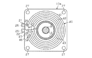
図5に示すように、別例2の基体10aにおいては、流路としての溝40が、駆動軸9の軸心と同心の円弧である外円部41、中円部42及び内円部43と、それぞれを屈曲点34で連結する放射状部45及び放射状部46とにより構成されている。そして、内円部43の端部と連通穴25とが放射状部47で連結されている。このように配置された溝40は比較的長い流路として得られるにも関わらず、NCによるエンドミル加工のための数値入力等を省力化することができる。
As shown in FIG. 5, in the
なお、溝40の円弧部分を、半径の異なる3個の外円部41、中円部42及び内円部43で構成したが、円弧の数はこれに限らず、溝40の幅を調整する等して、2個以下としたり4個以上としたりすることもできる。
In addition, although the circular arc part of the groove |
従って、上記実施形態によれば、以下のような効果を得ることができる。
(1)上記実施形態では、流路としての溝11を流れる冷却用流体により、モーター1のフランジ部13から連結フランジ10伝達された熱を奪うようにした。このため、モーター1のフランジ部13からフレーム2への熱伝達が阻止されるので、フレーム2の温度を上昇させる熱を、クイル4等を介して伝達されるラジアルベアリング5及びスラストベアリング6の熱に限定することができる。従って、フレーム2の温度調節が容易となって、熱膨張による歪の発生を阻止できるので、スピンドルの回転精度を高め、加工具によるワークの加工精度を向上させることができる。
Therefore, according to the above embodiment, the following effects can be obtained.
(1) In the above embodiment, the cooling fluid flowing through the groove 11 serving as the flow path takes away the heat transmitted from the
(2)上記実施形態では、モーター1の駆動軸9に直交する方向に配置される平面部であり、基体10aのフランジ部13に対向する面とは反対側の面に、溝11、30、40を形成し、その溝11、30、40を流路とした。このため、連結フランジの外周部の複数ヶ所からドリルにより孔を穿孔し、それぞれの孔の一部が交錯するようにして、流路を形成する場合と異なり、任意の形状の流路をエンドミル等を用いて容易に形成することができる。
(2) In the above-described embodiment, the
(3)上記実施形態では、流路としての溝11を、基準円23の内側と外側とに交互に位置を変える蛇行状に配置した。このため、流路が広範囲に亘ると共に、冷却用流体が流路をスムーズに流れることができるので、連結フランジ10の冷却を効率的に行うことができる。
(3) In the above embodiment, the grooves 11 as the flow paths are arranged in a meandering manner in which the positions are alternately changed between the inside and the outside of the
(4)上記実施形態では、複数の大径部31と小径部32とを、屈曲点34において放射状部33で連結して、より長い流路としての溝30を形成した。このため、連結フランジ10に供給されて排出されるまでの間に冷却用流体が連結フランジ10に接する面積が増えたので、冷却用流体は、モーター1から伝達された熱をより多く奪うことができる。
(4) In the above embodiment, the plurality of large-
(5)上記実施形態では、外円部41、中円部42及び内円部43を、複数の屈曲点34において放射状部45、46で連結して、より長い流路としての溝40を形成した。このため、冷却用流体がモーターから伝達された熱を効率的に奪うことができると共に、溝40を、NCによりエンドミル加工するための数値入力等を省力化することができる。
(5) In the above embodiment, the
(6)上記実施形態では、エンドミルを用いて溝11、30、40を一筆書き状に連続して形成した。このため、流路の途中に冷却用流体が行き止まりとなる部分の形成を未然に防止することができる。従って、温度調節された冷却用流体を連結フランジ10の冷却に効率よく用いることができる。また、その行き止まり部分に冷却用流体が流れ込まないように、堰き止めとして、例えばボスを打ち込む等の煩雑な作業を省くことができる。
(6) In the above embodiment, the
(7)上記実施形態では、基体10aと、その基体10aの溝11、30、40が形成された面を覆う副体10bとにより、内部に流路を有する連結フランジ10を形成した。このため、基体10aの溝11、30、40が形成された面と、モーター1のフランジ部13又はフレーム2の取付部19とを合わせて流路を形成する場合のように、フランジ部13又は取付部19において、液状シール剤を用いるために面粗度を上げるための仕上げ加工や、ガスケット等のシール材を配置するための溝加工等を省くことができる。
(7) In the above embodiment, the connecting
(第2の実施形態)
次に、本発明を具体化した第2実施形態を、第1実施形態と異なる部分を中心に図6を用いて説明する。なお、本実施形態は、第1実施形態とは副体10bを用いない点が異なるのみで他は同様な構成であるので、その異なる部分の説明をして、他の部分の説明は省略する。
(Second Embodiment)
Next, a second embodiment embodying the present invention will be described with reference to FIG. 6 with a focus on differences from the first embodiment. Note that this embodiment is the same as the first embodiment except that the sub-body 10b is not used, and the other parts are the same in configuration. Therefore, the description of the different parts is omitted and the description of the other parts is omitted. .
図6に示すように、連結フランジ50の溝11が形成された面は、直接フレーム2の取付部19に合わせられている。また、連結フランジ50には、駆動軸9の軸心と同心円の凸部51が形成され、その凸部51はフレーム2の凹部17に嵌合している。
As shown in FIG. 6, the surface of the connecting
このように、連結フランジ50と取付部19とを当接させ、溝11を冷却用流体のための流路とするために、図2において二点差線で示すシール位置24に対応する位置において、取付部19には、図示しないガスケット用の溝を設けてガスケットを装着している。
Thus, in order to bring the connecting
なお、本実施形態では、連結フランジ50の取付部19に対向する面に溝11を形成したが、連結フランジ50のフランジ部13に対向する面に溝11を形成することもできる。このとき、ガスケット等のシール材を用いるためには、シール材用の溝を、連結フランジ50又はフランジ部13のいずれかの面に形成する必要がある。液状シール剤を用いる場合は、溝の形成を省くことができる。また、流路は、図2で示した溝11に替えて、図4で示した溝30又は図5で示した溝40を用いることもできる。
In the present embodiment, the groove 11 is formed on the surface of the connecting
そして、この第2実施形態においては、第1の実施形態における効果に加えて、以下の効果を得ることができる。
(8)上記実施形態では、連結フランジ50と取付部19とを当接させ、溝11、30、40を冷却用流体のための流路とした。このため、部品点数を削減することができた。
And in this 2nd Embodiment, in addition to the effect in 1st Embodiment, the following effects can be acquired.
(8) In the said embodiment, the
(変更例)
なお、上記実施形態は、次のように変更して具体化することも可能である。
・ 基体10aに溝11、30、40をエンドミルで形成したが、基体10aをダイキャストで製造するようにして、溝11、30、40を成形型により形成すること。
・ 図2、4、5において供給連結部21と排出連結部22とを上下に配置したが、溝11、30、40の配置はそのままにして排出連結部22を上方に供給連結部21を下方に配置すること。
・ 溝30、40の屈曲点34において、内側の形状を角状としたが、円弧状とすること。
(Example of change)
In addition, the said embodiment can also be changed and actualized as follows.
The
2, 4 and 5, the
-Although the inner shape is square at the
1…モーター、2…フレーム、3…スピンドル、8…カップリング、9…駆動軸、10a…基体、10b…副体、11,30,40…溝、11c…変曲点、13…フランジ部、19…取付部、23…基準円、34…屈曲点。
DESCRIPTION OF
Claims (6)
Priority Applications (1)
| Application Number | Priority Date | Filing Date | Title |
|---|---|---|---|
| JP2009199286A JP2011051027A (en) | 2009-08-31 | 2009-08-31 | Connecting flange |
Applications Claiming Priority (1)
| Application Number | Priority Date | Filing Date | Title |
|---|---|---|---|
| JP2009199286A JP2011051027A (en) | 2009-08-31 | 2009-08-31 | Connecting flange |
Publications (1)
| Publication Number | Publication Date |
|---|---|
| JP2011051027A true JP2011051027A (en) | 2011-03-17 |
Family
ID=43940600
Family Applications (1)
| Application Number | Title | Priority Date | Filing Date |
|---|---|---|---|
| JP2009199286A Pending JP2011051027A (en) | 2009-08-31 | 2009-08-31 | Connecting flange |
Country Status (1)
| Country | Link |
|---|---|
| JP (1) | JP2011051027A (en) |
Cited By (3)
| Publication number | Priority date | Publication date | Assignee | Title |
|---|---|---|---|---|
| DE102012023525A1 (en) | 2011-12-09 | 2013-06-13 | Fanuc Corporation | Cooling plate for an electric motor with improved heat radiating ability |
| CN103433763A (en) * | 2013-08-16 | 2013-12-11 | 宁波菲仕运动控制技术有限公司 | Tool flange for finish turning and finish milling and usage method thereof |
| CN109531428A (en) * | 2017-09-21 | 2019-03-29 | 株式会社迪思科 | Processing unit (plant) |
Citations (1)
| Publication number | Priority date | Publication date | Assignee | Title |
|---|---|---|---|---|
| JPH0447954U (en) * | 1990-08-31 | 1992-04-23 |
-
2009
- 2009-08-31 JP JP2009199286A patent/JP2011051027A/en active Pending
Patent Citations (1)
| Publication number | Priority date | Publication date | Assignee | Title |
|---|---|---|---|---|
| JPH0447954U (en) * | 1990-08-31 | 1992-04-23 |
Cited By (5)
| Publication number | Priority date | Publication date | Assignee | Title |
|---|---|---|---|---|
| DE102012023525A1 (en) | 2011-12-09 | 2013-06-13 | Fanuc Corporation | Cooling plate for an electric motor with improved heat radiating ability |
| JP2013123309A (en) * | 2011-12-09 | 2013-06-20 | Fanuc Ltd | Electric motor cooling plate improving heat radiation performance |
| CN103433763A (en) * | 2013-08-16 | 2013-12-11 | 宁波菲仕运动控制技术有限公司 | Tool flange for finish turning and finish milling and usage method thereof |
| CN109531428A (en) * | 2017-09-21 | 2019-03-29 | 株式会社迪思科 | Processing unit (plant) |
| CN109531428B (en) * | 2017-09-21 | 2022-06-24 | 株式会社迪思科 | Processing device |
Similar Documents
| Publication | Publication Date | Title |
|---|---|---|
| JP5464879B2 (en) | Machine Tools | |
| JP6077852B2 (en) | Spinning molding equipment | |
| JP2016512313A (en) | Trailing edge cooling bearing | |
| US20110277325A1 (en) | Passage block and manufacturing method thereof | |
| JP2011051027A (en) | Connecting flange | |
| KR20080089341A (en) | Twin roll caster, and equipment and method for operating the same | |
| JP2009197943A (en) | Gas bearing spindle | |
| JP2009068649A (en) | Spindle device | |
| US20130136384A1 (en) | Rotary table for a machine tool | |
| KR102652217B1 (en) | Spindle of machine tool | |
| JP6708804B1 (en) | Table rotation device and machine tool | |
| KR20190095701A (en) | Cooling unit on rotary table of machine tools | |
| KR20140059322A (en) | Spindle head with improved structure | |
| CN108425865A (en) | Thin fan and thin motor | |
| CN104029119B (en) | Workhead hydrostatic spindle of bearing ring grinder | |
| JP3448732B2 (en) | Lead screw cooling system | |
| JP2015186829A (en) | Cooling structure of machine tool | |
| JP2011148062A (en) | Machine tool | |
| JP6645048B2 (en) | Hydrostatic bearing, method of manufacturing the same, and machine tool using the same | |
| JP2006263824A (en) | Spindle device | |
| JP4529129B2 (en) | Hydrostatic air bearing spindle | |
| CN114850514B (en) | Heat dissipation balance type ultra-high speed numerical control machine tool mandrel and heat dissipation optimization method thereof | |
| JP2002168319A (en) | Feed screw device | |
| CN216228323U (en) | Cooling structure for eliminating thermal deformation of gantry ram | |
| JP2011148061A (en) | Machine tool |
Legal Events
| Date | Code | Title | Description |
|---|---|---|---|
| A621 | Written request for application examination |
Free format text: JAPANESE INTERMEDIATE CODE: A621 Effective date: 20120510 |
|
| A131 | Notification of reasons for refusal |
Free format text: JAPANESE INTERMEDIATE CODE: A131 Effective date: 20130723 |
|
| A977 | Report on retrieval |
Free format text: JAPANESE INTERMEDIATE CODE: A971007 Effective date: 20130724 |
|
| A02 | Decision of refusal |
Free format text: JAPANESE INTERMEDIATE CODE: A02 Effective date: 20131119 |