JP2011050517A - Radiographic imaging apparatus and control method therefor - Google Patents
Radiographic imaging apparatus and control method therefor Download PDFInfo
- Publication number
- JP2011050517A JP2011050517A JP2009201089A JP2009201089A JP2011050517A JP 2011050517 A JP2011050517 A JP 2011050517A JP 2009201089 A JP2009201089 A JP 2009201089A JP 2009201089 A JP2009201089 A JP 2009201089A JP 2011050517 A JP2011050517 A JP 2011050517A
- Authority
- JP
- Japan
- Prior art keywords
- mode
- cooling
- detector
- gantry device
- image shooting
- Prior art date
- Legal status (The legal status is an assumption and is not a legal conclusion. Google has not performed a legal analysis and makes no representation as to the accuracy of the status listed.)
- Ceased
Links
- 238000003384 imaging method Methods 0.000 title claims abstract description 27
- 238000000034 method Methods 0.000 title claims abstract description 16
- 238000001816 cooling Methods 0.000 claims abstract description 100
- 230000007246 mechanism Effects 0.000 claims abstract description 49
- 238000001514 detection method Methods 0.000 claims abstract description 32
- 230000005855 radiation Effects 0.000 claims abstract description 25
- 230000007704 transition Effects 0.000 claims description 14
- 230000017525 heat dissipation Effects 0.000 description 17
- 230000033228 biological regulation Effects 0.000 description 12
- 230000008569 process Effects 0.000 description 7
- 238000010586 diagram Methods 0.000 description 3
- 230000000694 effects Effects 0.000 description 2
- 238000002601 radiography Methods 0.000 description 2
- 239000000758 substrate Substances 0.000 description 2
- 238000004891 communication Methods 0.000 description 1
- 239000000470 constituent Substances 0.000 description 1
- 230000001276 controlling effect Effects 0.000 description 1
- 230000006870 function Effects 0.000 description 1
- 238000005259 measurement Methods 0.000 description 1
- NJPPVKZQTLUDBO-UHFFFAOYSA-N novaluron Chemical compound C1=C(Cl)C(OC(F)(F)C(OC(F)(F)F)F)=CC=C1NC(=O)NC(=O)C1=C(F)C=CC=C1F NJPPVKZQTLUDBO-UHFFFAOYSA-N 0.000 description 1
- 230000001105 regulatory effect Effects 0.000 description 1
- 230000004044 response Effects 0.000 description 1
- 230000001502 supplementing effect Effects 0.000 description 1
- XLYOFNOQVPJJNP-UHFFFAOYSA-N water Substances O XLYOFNOQVPJJNP-UHFFFAOYSA-N 0.000 description 1
Images


Classifications
-
- G—PHYSICS
- G03—PHOTOGRAPHY; CINEMATOGRAPHY; ANALOGOUS TECHNIQUES USING WAVES OTHER THAN OPTICAL WAVES; ELECTROGRAPHY; HOLOGRAPHY
- G03B—APPARATUS OR ARRANGEMENTS FOR TAKING PHOTOGRAPHS OR FOR PROJECTING OR VIEWING THEM; APPARATUS OR ARRANGEMENTS EMPLOYING ANALOGOUS TECHNIQUES USING WAVES OTHER THAN OPTICAL WAVES; ACCESSORIES THEREFOR
- G03B42/00—Obtaining records using waves other than optical waves; Visualisation of such records by using optical means
- G03B42/02—Obtaining records using waves other than optical waves; Visualisation of such records by using optical means using X-rays
- G03B42/04—Holders for X-ray films
-
- A—HUMAN NECESSITIES
- A61—MEDICAL OR VETERINARY SCIENCE; HYGIENE
- A61B—DIAGNOSIS; SURGERY; IDENTIFICATION
- A61B6/00—Apparatus or devices for radiation diagnosis; Apparatus or devices for radiation diagnosis combined with radiation therapy equipment
- A61B6/52—Devices using data or image processing specially adapted for radiation diagnosis
- A61B6/5205—Devices using data or image processing specially adapted for radiation diagnosis involving processing of raw data to produce diagnostic data
Landscapes
- Health & Medical Sciences (AREA)
- Life Sciences & Earth Sciences (AREA)
- Engineering & Computer Science (AREA)
- Physics & Mathematics (AREA)
- Medical Informatics (AREA)
- General Physics & Mathematics (AREA)
- Pathology (AREA)
- Surgery (AREA)
- Nuclear Medicine, Radiotherapy & Molecular Imaging (AREA)
- Optics & Photonics (AREA)
- Biophysics (AREA)
- Radiology & Medical Imaging (AREA)
- Biomedical Technology (AREA)
- Heart & Thoracic Surgery (AREA)
- Molecular Biology (AREA)
- High Energy & Nuclear Physics (AREA)
- Animal Behavior & Ethology (AREA)
- General Health & Medical Sciences (AREA)
- Public Health (AREA)
- Veterinary Medicine (AREA)
- Computer Vision & Pattern Recognition (AREA)
- Apparatus For Radiation Diagnosis (AREA)
- Measurement Of Radiation (AREA)
Abstract
Description
本発明は、放射線画像撮影装置及びその制御方法に関する。 The present invention relates to a radiographic image capturing apparatus and a control method thereof.
DR(Digital Radiography)を用いたデジタル放射線撮影装置は、主に、静止画撮影に使用されている。また、このようなデジタル放射線撮影装置は、同程度の撮影エリアの大きさを有するI.I.型TV撮像系と比較すると、小型、軽量であることから、動画撮影にも使用されている。そのため、市場では、(DRを用いた)電子カセッテによる静止画撮影と、当該カセッテをテーブルや架台に設置した状態で行なう動画撮影とを兼用で行なうことが可能な検出器が要望されている。 Digital radiography apparatuses using DR (Digital Radiography) are mainly used for still image shooting. In addition, such a digital radiographic apparatus has an I.D. I. Compared to a type TV imaging system, it is smaller and lighter, so it is also used for moving image shooting. Therefore, there is a demand in the market for a detector that can be used for both still image shooting using an electronic cassette (using DR) and moving image shooting performed with the cassette placed on a table or a frame.
DRを用いた電子カセッテにおいて、連続撮影や動画撮影を行なう場合、静止画撮影時と比べ消費電力が増大する。そのため、このカセッテがテーブルや架台などの支持台内に設置される際は、冷却機構が支持台に設けられる。これにより、カセッテ内部の温度の検知に基づいて冷却機構の運転を制御する技術が知られている(特許文献1参照)。 In an electronic cassette using DR, when continuous shooting or moving image shooting is performed, power consumption increases as compared to still image shooting. Therefore, when the cassette is installed in a support table such as a table or a gantry, a cooling mechanism is provided on the support table. Thus, a technique for controlling the operation of the cooling mechanism based on the detection of the temperature inside the cassette is known (see Patent Document 1).
電子カセッテを支持台内に設置して使用する場合、電子カセッテは患者に触れない。そのため、電子カセッテの外装温度規定を満たす必要はないが、電子カセッテが支持台から取り出された後は、電子カセッテは外装温度規定を満たす必要がある。 When the electronic cassette is installed in a support base and used, the electronic cassette does not touch the patient. For this reason, it is not necessary to satisfy the exterior temperature regulation of the electronic cassette, but the electronic cassette needs to satisfy the exterior temperature regulation after the electronic cassette is taken out from the support base.
一般的に、冷却機構は、コストや構成の簡便さからファンを使用することが多い。しかし、当該ファンを用いて、常時冷却を行なった場合、モータ音によるノイズや電力消費が無駄に大きくなり、非効率である。また、被検者に対しても余計な不快感を与えてしまう。例えば、上述した特許文献1に開示された技術では、カセッテ内部の温度検知結果のみを冷却の制御基準としているため、動画撮影時も静止画撮影時も常に、カセッテの外装温度規定を満たす冷却を行なってしまう。そのため、例えば、静止画撮影時にも無駄な冷却を行なうことになる。
In general, a cooling mechanism often uses a fan because of its cost and simple structure. However, when cooling is always performed using the fan, noise due to motor noise and power consumption increase unnecessarily, which is inefficient. In addition, the subject is uncomfortable. For example, in the technique disclosed in
そこで、本発明は、上記課題に鑑みてなされたものであり、動画撮影又は静止画撮影のいずれが行なわれているかによって電子カセッテの冷却モードを切り替えるようにした技術を提供することを目的とする。 Therefore, the present invention has been made in view of the above problems, and an object of the present invention is to provide a technique for switching the cooling mode of an electronic cassette depending on whether moving image shooting or still image shooting is performed. .
上記課題を解決するため、本発明の一態様による放射線画像撮影装置は、架台装置に着脱可能であり、動画撮影モードと静止画撮影モードとのいずれかで被写体を透過した放射線を検出する検出器と、前記検出器における撮影モードの移行タイミングを検知する検知手段と、第1の冷却モードと、該第1の冷却モードよりも冷却能力の高い第2の冷却モードとのいずれかにより前記検出器を冷却する冷却機構と、前記検知手段による検知に基づいて前記冷却機構の冷却モードを切り替える制御手段とを具備することを特徴とする。 In order to solve the above-described problem, a radiographic imaging device according to an aspect of the present invention is a detector that is detachable from a gantry device and detects radiation transmitted through a subject in either a moving image shooting mode or a still image shooting mode. Detecting means for detecting the transition timing of the photographing mode in the detector, the first cooling mode, and the second cooling mode having a higher cooling capacity than the first cooling mode. And a control means for switching the cooling mode of the cooling mechanism based on detection by the detection means.
本発明によれば、動画撮影又は静止画撮影のいずれが行なわれているかによって電子カセッテの冷却モードを切り替えることができる。 According to the present invention, the cooling mode of the electronic cassette can be switched depending on whether moving image shooting or still image shooting is performed.
以下、本発明に係わる放射線画像撮影装置及びその制御方法の一実施の形態について添付図面を参照して詳細に説明する。 Hereinafter, an embodiment of a radiographic imaging apparatus and a control method thereof according to the present invention will be described in detail with reference to the accompanying drawings.
なお、以下に示す実施形態においては、放射線としてX線を適用した場合を例に挙げて説明するが、放射線は、X線に限られず、例えば、電磁波やα線、β線、γ線などであってもよい。 In the embodiment described below, a case where X-rays are applied as radiation will be described as an example. However, the radiation is not limited to X-rays, for example, electromagnetic waves, α rays, β rays, γ rays, or the like. There may be.
(実施形態1)
図1は、本発明の一実施の形態に係わる放射線画像撮影装置の構成の一例を示す図である。
(Embodiment 1)
FIG. 1 is a diagram showing an example of a configuration of a radiographic image capturing apparatus according to an embodiment of the present invention.
放射線画像撮影装置20は、冷却制御装置10と、架台装置7とを具備して構成される。冷却制御装置10及び架台装置7は、ケーブル11により通信可能に接続されている。
The
架台装置7は、患者を支持する台であり、電子カセッテ(以下、カセッテ、検出器と略す場合もある)100が着脱可能に搭載される。架台装置7としては、例えば、臥位テーブルや立位架台、ユニバーサル架台等が挙げられる。
The
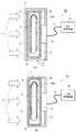
ここで、電子カセッテ100は、被写体(本実施形態においては、被検者とする)を透過した放射線を検出し、当該被写体に基づく放射線画像を取得する。電子カセッテ100は、架台装置7に搭載されて使用される他、単体で可搬可能に使用される。なお、本実施形態においては、電子カセッテ100が可搬可能に使用される場合、静止画撮影(静止画撮影モード)が行なわれ、電子カセッテ100が架台に搭載された状態で使用される場合、動画撮影(動画撮影モード)が行なわれる。図1(a)の場合、架台装置7の側面が開閉し、当該側面から電子カセッテ100が挿入され、架台装置7に搭載される。また、図1(b)の場合、放射線の入射方向1側の面が開口しており、この開口面から電子カセッテ100が挿入され、架台装置7に搭載される。なお、静止画撮影モードとは、1度の放射線の曝射に対して1度の撮影を行なうモードであり、動画撮影モードは、1度の放射線の曝射に対して連続して撮影を行なうモードである。
Here, the
架台装置7には、検知部9が設けられる。検知部9は、撮影モード(動画撮影モード、静止画撮影モード)の移行タイミングを検知する。図1(a)の場合、検知部9は、架台装置7の側面が開いたことを検知し、これにより、撮影モードの移行タイミングを検知する。なお、検知部9は、電子カセッテ100を着脱する際に操作者が触れる箇所、例えば、ハンドル部に配置されていてもよい。この場合、電子カセッテ100を着脱する架台装置7の側面が開口されていることが好ましい。また、図1(b)の場合、架台装置7の放射線入射方向1側の端部に検知部9が設けられている。この場合、検知部9は、赤外線センサ等で実現され、被検者が所定範囲内に近接したことを検知する。これにより、撮影モードの移行タイミングを検知する。
The
ここで、電子カセッテ100は、その外装6の中に、電子基板3と、支持基台5と、放射線検出部2とが具備される。1は、放射線の入射方向を示しており、放射線検出部2においては、被検者から透過した当該放射線を検出する。電子基板3は、電気信号線4を介して放射線検出部2により検出された信号を受け取り、それを処理する。また、支持基台5は、放射線検出部2を支持する。
Here, the
架台装置7には、電子カセッテ外装6を冷却する冷却機構8が設けられる。本実施形態に係わる冷却機構8は、通常放熱モード(第1の冷却モード)と高放熱モード(第2の冷却モード)との2段階で動作する。なお、高放熱モードとは、通常放熱モードよりも冷却能力の高いモードをいう。冷却機構8は、どのような構成で実現されてもよく、例えば、ペルチェ素子やファン、水冷機構など、接触型、非接触型の冷却機構、いずれであってもよい。また、その配置箇所は、架台装置7の放射線入射方向1側の面を除けば、いずれの面であってもよい。また更に、電子カセッテ内部に配置してもよい。なお、本実施形態においては、冷却機構8は、2段階以上で出力を調節可能な冷却機構を用いる場合を例に挙げて説明するが、これに限られない。例えば、冷却機構8を複数個配置してそれらを選択的に駆動させるように構成してもよい。この場合、例えば、通常放熱モードでは、1つの冷却機構を駆動し、高放熱モードでは、2つ以上の冷却機構を駆動する等する。
The
冷却制御装置10は、冷却機構8の駆動を制御する。冷却制御装置10は、架台装置7の内部に配置されてもよい。なお、冷却制御装置10は、1又は複数のコンピュータを含んで構成される。コンピュータには、例えば、CPU等の主制御手段、ROM(Read Only Memory)、RAM(Random Access Memory)等の記憶手段が具備される。また、コンピュータには、ネットワークカード等の通信手段、キーボード、ディスプレイ又はタッチパネル等の入出力手段等、が具備されていてもよい。なお、これら各構成手段は、バス等により接続され、主制御手段が記憶手段に記憶されたプログラムを実行することで制御される。
The cooling
図2は、図1(a)に示す放射線画像撮影装置20における撮影動作の一例を示すフローチャートである。ここでは、説明の便宜上、架台装置7に電子カセッテが搭載されている状態から撮影が始まったものとして説明する。
FIG. 2 is a flowchart illustrating an example of an imaging operation in the radiographic
放射線画像撮影装置20は、電子カセッテ100が架台装置7に搭載されているため、動画撮影モードで放射線画像を撮影する。このとき、冷却機構8は、通常放熱モードで動作し、電子カセッテ100を冷却する。この状態は、検知部9により架台装置7から電子カセッテ100が取り外されたことを検知するか、又はユーザにより撮影の終了が指示されるかするまで継続する(S1でNOの後、S2でNO)。
The radiographic
ここでユーザにより撮影の終了が指示された場合(S2でYES)、そのままこの処理は終了する。また、検知部9において、架台装置7から電子カセッテ100が取り外されたことを検知(すなわち、撮影モードの移行タイミングを検知)した場合(S1でYES)、放射線画像撮影装置20は、その旨を冷却制御装置10に通知する。また、撮影モードを静止画撮影モードに移行させる(S3)。
If the user instructs the end of shooting (YES in S2), the process ends as it is. Further, when the
ここで、冷却機構8は、冷却制御装置10からの指示に基づいて高放熱モードでの動作を開始する(S4)。この状態は、検知部9により電子カセッテ100が架台装置7に搭載されたことを検知するか、又はユーザにより撮影の終了が指示されるかするまで継続する(S5でNOの後、S6でNO)。なお、上述した通り、静止画撮影モードでは、電子カセッテの外装6に被検者が接触した状態で撮影が行なわれる。
Here, the
ここでユーザにより撮影の終了が指示された場合(S6でYES)、そのままこの処理は終了する。また、検知部9において、電子カセッテ100が架台装置7に搭載されたことを検知した場合(S5でYES)、放射線画像撮影装置20は、その旨を冷却制御装置10に通知するとともに、動画撮影モードに移行する(S7)。また、冷却機構8は、冷却制御装置10からの指示に基づいて通常放熱モードでの動作を開始する(S8)。その後、放射線画像撮影装置20は、再度、S1の処理に戻る。
If the user instructs the end of shooting (YES in S6), the process ends as it is. When the
図3は、電子カセッテ外装6の温度分布の概要の一例を示している。
FIG. 3 shows an example of the outline of the temperature distribution of the
T1は、電子カセッテ外装温度規定値であり、これより温度が上昇すると、被検者の接触を避けなければならない。H1は、動画撮影モードから静止画撮影モードへの移行タイミングを示しており、H2は、電子カセッテ100が架台装置7から実際に取り外されたタイミングを示している。L1は、動画撮影モードを継続した場合における時間と電子カセッテ外装温度との関係を示している。また、L2は、H1のタイミングで通常放熱モードから高放熱モードへ移行した場合における時間と電子カセッテ外装温度との関係を示している。
T1 is an electronic cassette exterior temperature regulation value, and when the temperature rises from this, contact of the subject must be avoided. H1 indicates the transition timing from the moving image shooting mode to the still image shooting mode, and H2 indicates the timing when the
図3に示すように、電子カセッテ100が架台装置7から取り外されると、冷却機構8が高放熱モードで動作するため、電子カセッテ外装6の温度規定を満足させることができる。
As shown in FIG. 3, when the
以上説明したように実施形態1によれば、撮影モードに応じて電子カセッテの冷却モードを切り替える。具体的には、架台装置7に搭載されて電子カセッテが使用される場合には、通常の冷却が行なわれ、可搬可能に電子カセッテが使用される場合には、高放熱な冷却が行なわれる。これにより、電力消費を抑えつつ冷却を適切に行なうことができるため、冷却の効率化を図ることができる。
As described above, according to the first embodiment, the cooling mode of the electronic cassette is switched according to the shooting mode. Specifically, when the electronic cassette is mounted on the
(実施形態2)
図4は、実施形態2に係わる放射線画像撮影装置20の構成の一例を示す図である。ここでは、実施形態1を説明した図1と同様の構成については、同一の構成を付し、その説明については省略する場合もある。なお、図1(b)で説明した構成についての説明はここでは省略する。
(Embodiment 2)
FIG. 4 is a diagram illustrating an example of the configuration of the radiation
実施形態2に係わる放射線画像撮影装置20には、温度センサ14と、ロック機構15とが新たに設けられる。
The radiation
温度センサ14は、特に、電子カセッテ外装6の表面温度を検知する。なお、実施形態2に係わる温度センサ14は、電子基板3上に配置されているが、電子カセッテ外装温度は、事前の測定による電子カセッテの温度分布から算出することもできるため、他の場所に配置するようにしてもよい。例えば、撮影に支障がないのであれば、電子カセッテ100の表面、又は内部のどこに配置してもよい。
In particular, the
ロック機構15は、架台装置7からの電子カセッテ100の取り外しを禁止すべく開平扉をロックする。具体的には、架台装置7の開閉面が開くことを禁止する。なお、実施形態1で説明した図1(b)に対応する架台装置(開閉面が開口面である)の場合には、例えば、架台装置内部に電子カセッテが引っかかる回転可能な突起物をロック機構として配置すればよい。そして、突起物の回転を禁止することで電子カセッテ100の取り外しを禁止する。
The
また、実施形態2に係わる冷却制御装置10は、実施形態1に加えて、温度センサ14の信号を受け取り、当該信号に基づいてロック機構15の制御を行なう。
In addition to the first embodiment, the cooling
次に、図5を用いて、実施形態2に係わる放射線画像撮影装置20における撮影動作の一例について説明する。ここでは、電子カセッテ100が可搬可能に使用される場合(架台装置7に未搭載)の処理は、実施形態1同様となるので、電子カセッテ100が架台装置7に搭載されている場合の処理について説明を行なう。
Next, an example of an imaging operation in the radiographic
電子カセッテ100が架台装置7に搭載されると(S11でYES)、放射線画像撮影装置20は、動画撮影モードでの撮影を開始する(S13)。このとき、冷却機構8は、通常放熱モードで動作し、電子カセッテ100を冷却する(S14)。電子カセッテ100が架台装置7に搭載されている間、温度センサ14は、電子カセッテ外装6から検知した表面温度を冷却制御装置10に向けて随時通知する。
When the
電子カセッテ100が架台装置7に搭載されている間、、冷却制御装置10は、温度センサ14から通知された温度に基づいて、電子カセッテ外装6が温度規定を満たしているか否かを判断する。すなわち、電子カセッテ外装6の温度が、所定の温度を越えているか(温度規定を満たしていない)、又は所定の温度以下(温度規定を満たしている)であるかを判断する。
While the
判断の結果、温度規定が満たされていなければ(S15でNO)、冷却制御装置10は、冷却機構8に向けて高放熱モードでの動作を指示するとともに、ロック機構15に向けてロック作動を指示する。これにより、冷却機構8は、高放熱モードでの動作を開始し(S16)、また、ロック機構15は、開平扉をロックする(S17)。
If the temperature regulation is not satisfied as a result of the determination (NO in S15), the cooling
また、S15における判断の結果、温度規定が満たされていれば(S15でYES)、冷却制御装置10は、ロック作動中であるか否かを判断する。そして、ロック作動中であれば(S18でYES)、冷却機構8に向けて通常放熱モードでの動作を指示するとともに、ロック機構15に向けてロック解除を指示する。これにより、冷却機構8は、通常放熱モードでの動作を開始し(S19)、また、ロック機構15は、開平扉のロックを解除する(S20)。その後、放射線画像撮影装置20は、検知部9により架台装置7から電子カセッテ100が取り外されたことを検知するか、又はユーザにより撮影の終了が指示されるかするまでS15〜S22の処理が繰り返し実施される(S21でNOの後、S22でNO)。
Further, as a result of the determination in S15, if the temperature regulation is satisfied (YES in S15), the cooling
以上説明したように実施形態2によれば、動画撮影を長時間行なった場合や、デューティエラー等により電子カセッテが予期せぬ高温状態に陥った場合であっても、電子カセッテ外装6の温度規定を満足させられるため、安全性が向上する。
As described above, according to the second embodiment, even when a moving image is taken for a long time or when the electronic cassette falls into an unexpectedly high temperature due to a duty error or the like, the temperature regulation of the
なお、上述した実施形態2においては、放射線画像撮影装置20に温度センサ14を設ける場合について説明したが、温度センサ14を省略してもよい。この場合、冷却制御装置10は、外部(例えば、RIS(放射線部門情報管理システム))から撮影条件の履歴を取得し、当該取得した履歴と電子カセッテ100の温度特性とに基づいて必要な冷却時間(規定温度以下にするまでに要する時間)を算出する。そして、撮影モードの変更に際しては(動作撮影から静止画撮影への移行)、当該冷却時間の間、ロックを作動させ、当該時間が経過するとロックを解除する。図5を用いて補足すると、S16の処理において、冷却制御装置10は、撮影条件の履歴と電子カセッテ100の温度特性とに基づいて、必要な冷却時間(この場合、H1とH2との差)を算出する。そして、当該算出した冷却時間、冷却機構8を高放熱モードで動作させるとともに、ロックを作動させる。これにより、電子カセッテ100が架台装置7から取り外されるときには、電子カセッテ外装の温度は、温度規定を満足するまで降下する。
In addition, in
以上が本発明の代表的な実施形態の一例であるが、本発明は、上記及び図面に示す実施形態に限定することなく、その要旨を変更しない範囲内で適宜変形して実施できるものである。 The above is an example of a typical embodiment of the present invention, but the present invention is not limited to the embodiment described above and shown in the drawings, and can be appropriately modified and implemented without departing from the scope of the present invention. .
例えば、上記実施形態1及び2においては、RIS(放射線部門情報管理システム)を用いた構成については特に言及していないが、RISからの情報を活用してもよい。例えば、冷却制御装置10において、これから検査が行なわれる撮影の条件等の情報をRISから取得し、当該情報に基づいて、動画撮影モードから静止画撮影モードに移行する時刻を算出し、冷却機構8の駆動を制御するようにしてもよい。この場合、温度センサが不要になるのでコストダウンを図れる。また、動画撮影モードから静止画撮影モードへの移行を前もって検知するため、静止画撮影モードに向けた冷却を事前に開始することもできるため、より効率的な放熱が行なえる。
For example, in the first and second embodiments, the configuration using the RIS (Radiation Department Information Management System) is not particularly mentioned, but information from the RIS may be used. For example, the cooling
また、本発明は、例えば、システム、装置、方法、プログラム若しくは記憶媒体等としての実施態様を採ることもできる。具体的には、複数の機器から構成されるシステムに適用してもよいし、また、一つの機器からなる装置に適用してもよい。 In addition, the present invention can take an embodiment as a system, apparatus, method, program, storage medium, or the like. Specifically, the present invention may be applied to a system composed of a plurality of devices, or may be applied to an apparatus composed of a single device.
(その他の実施形態)
また、本発明は、以下の処理を実行することによっても実現される。
即ち、上述した実施形態の機能を実現するソフトウェア(プログラム)を、ネットワーク又は各種記憶媒体を介してシステム或いは装置に供給し、そのシステム或いは装置のコンピュータ(又はCPUやMPU等)がプログラムを読み出して実行する処理である。
(Other embodiments)
The present invention can also be realized by executing the following processing.
That is, software (program) that realizes the functions of the above-described embodiments is supplied to a system or apparatus via a network or various storage media, and a computer (or CPU, MPU, etc.) of the system or apparatus reads the program. It is a process to be executed.
Claims (8)
前記検出器における撮影モードの移行タイミングを検知する検知手段と、
第1の冷却モードと、該第1の冷却モードよりも冷却能力の高い第2の冷却モードとのいずれかにより前記検出器を冷却する冷却機構と、
前記検知手段による検知に基づいて前記冷却機構の冷却モードを切り替える制御手段と
を具備することを特徴とする放射線画像撮影装置。 A detector that is attachable to and detachable from the gantry device, and that detects radiation that has passed through the subject in either the video shooting mode or still image shooting mode;
Detection means for detecting the transition timing of the photographing mode in the detector;
A cooling mechanism for cooling the detector by any one of a first cooling mode and a second cooling mode having a higher cooling capacity than the first cooling mode;
A radiographic imaging apparatus comprising: control means for switching a cooling mode of the cooling mechanism based on detection by the detection means.
前記架台装置に搭載された場合に動画撮影モードで動作し、前記架台装置から取り外され可搬可能に使用される場合に静止画撮影モードで動作し、
前記制御手段は、
前記検知手段により前記動画撮影モードから前記静止画撮影モードへの移行タイミングが検知された場合、前記冷却機構を前記第2の冷却モードで動作させ、前記検知手段により前記静止画撮影モードから前記動画撮影モードへの移行タイミングが検知された場合、前記冷却機構を前記第1の冷却モードで動作させる
ことを特徴とする請求項1記載の放射線画像撮影装置。 The detector is
Operates in video shooting mode when mounted on the gantry device, operates in still image shooting mode when used detachably from the gantry device,
The control means includes
When the detection means detects the transition timing from the moving image shooting mode to the still image shooting mode, the cooling mechanism is operated in the second cooling mode, and the detecting means moves the still image shooting mode to the moving image. The radiographic image capturing apparatus according to claim 1, wherein the cooling mechanism is operated in the first cooling mode when the timing of transition to the imaging mode is detected.
前記架台装置に対する前記検出器の搭載又は取り外しに基づいて前記撮影モードの移行タイミングを検知する
ことを特徴とする請求項1記載の放射線画像撮影装置。 The detection means includes
The radiographic image capturing apparatus according to claim 1, wherein transition timing of the imaging mode is detected based on mounting or removal of the detector with respect to the gantry device.
外部から取得した撮影条件を含む情報に基づいて前記撮影モードの移行タイミングを検知する
ことを特徴とする請求項1記載の放射線画像撮影装置。 The detection means includes
The radiographic image capturing apparatus according to claim 1, wherein the transition timing of the imaging mode is detected based on information including imaging conditions acquired from the outside.
前記検出器に対する前記被写体の所定範囲内への近接に基づいて前記撮影モードの移行タイミングを検知する
ことを特徴とする請求項1記載の放射線画像撮影装置。 The detection means includes
The radiographic image capturing apparatus according to claim 1, wherein transition timing of the imaging mode is detected based on proximity of the subject within a predetermined range with respect to the detector.
ロックを作動させて前記架台装置からの前記検出器の取り外しを禁止するロック機構と
を更に具備し、
前記制御手段は、
前記検出器が前記架台装置に搭載されている場合に、前記温度センサからの温度が所定の温度を越えているときには、前記ロック機構によるロックを作動させるとともに前記冷却機構を前記第2の冷却モードで動作させ、前記温度センサからの温度が所定の温度以下のときには、前記ロック機構によるロックを解除させるとともに前記冷却機構を前記第1の冷却モードで動作させる
ことを特徴とする請求項1記載の放射線画像撮影装置。 A temperature sensor for detecting a surface temperature of the detector;
A lock mechanism that operates a lock to prohibit removal of the detector from the gantry device,
The control means includes
When the detector is mounted on the gantry device, when the temperature from the temperature sensor exceeds a predetermined temperature, the lock mechanism is operated and the cooling mechanism is moved to the second cooling mode. 2. The operation according to claim 1, wherein when the temperature from the temperature sensor is equal to or lower than a predetermined temperature, the lock by the lock mechanism is released and the cooling mechanism is operated in the first cooling mode. Radiation imaging device.
を更に具備し、
前記制御手段は、
前記検出器が前記架台装置に搭載されている場合に、前記検知手段により前記動画撮影モードから前記静止画撮影モードへの移行タイミングが検知されたときには、外部から取得した撮影条件の履歴に基づいて算出された前記冷却機構が所定の温度以下になるのに要する時間の間、前記ロック機構によるロックを作動させる
ことを特徴とする請求項2記載の放射線画像撮影装置。 A lock mechanism for operating the lock to prohibit removal of the detector from the gantry device;
The control means includes
When the detector is mounted on the gantry device and the detection means detects the transition timing from the moving image shooting mode to the still image shooting mode, it is based on a history of shooting conditions acquired from the outside. The radiographic image capturing apparatus according to claim 2, wherein the lock mechanism is operated during a time required for the calculated cooling mechanism to be equal to or lower than a predetermined temperature.
検出器が、架台装置に着脱可能であり、動画撮影モードと静止画撮影モードとのいずれかで被写体を透過した放射線を検出する工程と、
検知手段が、前記検出器における撮影モードの移行タイミングを検知する工程と、
冷却機構が、第1の冷却モードと、該第1の冷却モードよりも冷却能力の高い第2の冷却モードとのいずれかにより前記検出器を冷却する工程と、
制御手段が、前記検知手段による検知に基づいて前記冷却機構の冷却モードを切り替える工程と
を含むことを特徴とする制御方法。 A method for controlling a radiographic imaging device, comprising:
A detector is attachable to and detachable from the gantry device and detects radiation transmitted through the subject in either the moving image shooting mode or the still image shooting mode;
A step of detecting the detection timing of the photographing mode in the detector;
A cooling mechanism that cools the detector by one of a first cooling mode and a second cooling mode having a higher cooling capacity than the first cooling mode;
And a step of switching the cooling mode of the cooling mechanism based on detection by the detection means.
Priority Applications (3)
| Application Number | Priority Date | Filing Date | Title |
|---|---|---|---|
| JP2009201089A JP2011050517A (en) | 2009-08-31 | 2009-08-31 | Radiographic imaging apparatus and control method therefor |
| US12/852,016 US8754380B2 (en) | 2009-08-31 | 2010-08-06 | Radiographic imaging apparatus and control method therefor |
| US14/261,561 US9433394B2 (en) | 2009-08-31 | 2014-04-25 | Radiographic imaging apparatus and control method therefor |
Applications Claiming Priority (1)
| Application Number | Priority Date | Filing Date | Title |
|---|---|---|---|
| JP2009201089A JP2011050517A (en) | 2009-08-31 | 2009-08-31 | Radiographic imaging apparatus and control method therefor |
Publications (2)
| Publication Number | Publication Date |
|---|---|
| JP2011050517A true JP2011050517A (en) | 2011-03-17 |
| JP2011050517A5 JP2011050517A5 (en) | 2012-10-18 |
Family
ID=43623438
Family Applications (1)
| Application Number | Title | Priority Date | Filing Date |
|---|---|---|---|
| JP2009201089A Ceased JP2011050517A (en) | 2009-08-31 | 2009-08-31 | Radiographic imaging apparatus and control method therefor |
Country Status (2)
| Country | Link |
|---|---|
| US (2) | US8754380B2 (en) |
| JP (1) | JP2011050517A (en) |
Cited By (1)
| Publication number | Priority date | Publication date | Assignee | Title |
|---|---|---|---|---|
| JP2021112464A (en) * | 2020-01-21 | 2021-08-05 | キヤノンメディカルシステムズ株式会社 | X-ray ct apparatus |
Families Citing this family (10)
| Publication number | Priority date | Publication date | Assignee | Title |
|---|---|---|---|---|
| JP2011050517A (en) * | 2009-08-31 | 2011-03-17 | Canon Inc | Radiographic imaging apparatus and control method therefor |
| JP5646289B2 (en) * | 2010-11-09 | 2014-12-24 | 株式会社東芝 | Radiation detector |
| JP5902186B2 (en) * | 2011-09-29 | 2016-04-13 | 富士フイルム株式会社 | Radiographic system and radiographic method |
| JP2014155620A (en) | 2013-02-15 | 2014-08-28 | Canon Inc | Movable x-ray generation apparatus |
| JP6557455B2 (en) * | 2014-06-25 | 2019-08-07 | キヤノン株式会社 | Imaging apparatus, control method therefor, program, and storage medium |
| WO2016061125A1 (en) | 2014-10-15 | 2016-04-21 | California Institute Of Technology | Contact lens with metered liquid system |
| JP6387045B2 (en) * | 2016-05-26 | 2018-09-05 | キヤノン株式会社 | Radiation imaging apparatus and control method thereof |
| JP7071083B2 (en) * | 2017-10-06 | 2022-05-18 | キヤノン株式会社 | Radiation imaging device |
| US11523939B2 (en) | 2018-05-22 | 2022-12-13 | California Institute Of Technology | Miniature fixed and adjustable flow restrictor for the body |
| JP6762994B2 (en) | 2018-07-31 | 2020-09-30 | キヤノン株式会社 | Radiation imaging device |
Citations (9)
| Publication number | Priority date | Publication date | Assignee | Title |
|---|---|---|---|---|
| JPH03289094A (en) * | 1990-04-03 | 1991-12-19 | Toshiba Corp | Radiographic apparatus |
| JP2003307569A (en) * | 2002-04-16 | 2003-10-31 | Canon Inc | Radiographic device, radiographic method, computer program, and computer-readable recording medium |
| JP2004104611A (en) * | 2002-09-11 | 2004-04-02 | Fuji Photo Film Co Ltd | Imaging device |
| JP2005181922A (en) * | 2003-12-24 | 2005-07-07 | Canon Inc | X-ray radiographing apparatus |
| JP2007289281A (en) * | 2006-04-21 | 2007-11-08 | Canon Inc | Radiation imaging device |
| JP2008036399A (en) * | 2006-07-10 | 2008-02-21 | Canon Inc | Radiation imaging apparatus and control method thereof |
| JP2008083031A (en) * | 2006-08-29 | 2008-04-10 | Canon Inc | Electronic cassette type radiation detector |
| JP2009028234A (en) * | 2007-07-26 | 2009-02-12 | Fujifilm Corp | Radiation imaging system |
| JP2009178443A (en) * | 2008-01-31 | 2009-08-13 | Canon Inc | Radiographic imaging apparatus and method of driving the same |
Family Cites Families (3)
| Publication number | Priority date | Publication date | Assignee | Title |
|---|---|---|---|---|
| US5567944A (en) * | 1995-04-28 | 1996-10-22 | University Of Cincinnati | Compton camera for in vivo medical imaging of radiopharmaceuticals |
| US8094898B2 (en) * | 2008-07-16 | 2012-01-10 | Siemens Medical Solutions Usa, Inc. | Functional image quality assessment |
| JP2011050517A (en) * | 2009-08-31 | 2011-03-17 | Canon Inc | Radiographic imaging apparatus and control method therefor |
-
2009
- 2009-08-31 JP JP2009201089A patent/JP2011050517A/en not_active Ceased
-
2010
- 2010-08-06 US US12/852,016 patent/US8754380B2/en not_active Expired - Fee Related
-
2014
- 2014-04-25 US US14/261,561 patent/US9433394B2/en not_active Expired - Fee Related
Patent Citations (9)
| Publication number | Priority date | Publication date | Assignee | Title |
|---|---|---|---|---|
| JPH03289094A (en) * | 1990-04-03 | 1991-12-19 | Toshiba Corp | Radiographic apparatus |
| JP2003307569A (en) * | 2002-04-16 | 2003-10-31 | Canon Inc | Radiographic device, radiographic method, computer program, and computer-readable recording medium |
| JP2004104611A (en) * | 2002-09-11 | 2004-04-02 | Fuji Photo Film Co Ltd | Imaging device |
| JP2005181922A (en) * | 2003-12-24 | 2005-07-07 | Canon Inc | X-ray radiographing apparatus |
| JP2007289281A (en) * | 2006-04-21 | 2007-11-08 | Canon Inc | Radiation imaging device |
| JP2008036399A (en) * | 2006-07-10 | 2008-02-21 | Canon Inc | Radiation imaging apparatus and control method thereof |
| JP2008083031A (en) * | 2006-08-29 | 2008-04-10 | Canon Inc | Electronic cassette type radiation detector |
| JP2009028234A (en) * | 2007-07-26 | 2009-02-12 | Fujifilm Corp | Radiation imaging system |
| JP2009178443A (en) * | 2008-01-31 | 2009-08-13 | Canon Inc | Radiographic imaging apparatus and method of driving the same |
Cited By (2)
| Publication number | Priority date | Publication date | Assignee | Title |
|---|---|---|---|---|
| JP2021112464A (en) * | 2020-01-21 | 2021-08-05 | キヤノンメディカルシステムズ株式会社 | X-ray ct apparatus |
| JP7493944B2 (en) | 2020-01-21 | 2024-06-03 | キヤノンメディカルシステムズ株式会社 | X-ray CT scanner |
Also Published As
| Publication number | Publication date |
|---|---|
| US20140236006A1 (en) | 2014-08-21 |
| US20110049378A1 (en) | 2011-03-03 |
| US9433394B2 (en) | 2016-09-06 |
| US8754380B2 (en) | 2014-06-17 |
Similar Documents
| Publication | Publication Date | Title |
|---|---|---|
| JP2011050517A (en) | Radiographic imaging apparatus and control method therefor | |
| JP5224726B2 (en) | Radiation imaging apparatus and control method thereof | |
| JP5854580B2 (en) | X-ray imaging apparatus and control method | |
| TW200846889A (en) | Electronic device thermal management system and method | |
| WO2014109336A1 (en) | Medical image photography device | |
| JP2011119302A (en) | Information processor | |
| JP2008099809A (en) | Radiographic imaging equipment | |
| JP2010237543A (en) | Radiation imaging device | |
| US20080074501A1 (en) | Imaging device and control method therefor, and program for the same | |
| JP2009056066A (en) | X-ray ct apparatus and its control method | |
| JP2015169926A (en) | projector | |
| CN111358477B (en) | Mobile X-ray imaging equipment | |
| JP6642512B2 (en) | Electronic equipment and image forming apparatus | |
| JP5619203B2 (en) | Radiation imaging apparatus, control apparatus, and control method | |
| JP5608889B2 (en) | Electronic control unit | |
| JP5203040B2 (en) | X-ray CT system | |
| JP2017139584A (en) | Imaging device | |
| JP5728897B2 (en) | Charging system | |
| JP5202742B2 (en) | Radiation imaging apparatus, control method therefor, and program | |
| JP2025012337A (en) | Radiography equipment | |
| JP2007080977A (en) | Power consumption unit and image processing apparatus | |
| JPH0837612A (en) | Image pickup device | |
| JP4600694B2 (en) | Heat dissipation device and fan control method | |
| JP2007306053A (en) | Portable electronic devices | |
| JP2005128135A (en) | Image forming apparatus and control program for the same |
Legal Events
| Date | Code | Title | Description |
|---|---|---|---|
| A521 | Request for written amendment filed |
Free format text: JAPANESE INTERMEDIATE CODE: A523 Effective date: 20120830 |
|
| A621 | Written request for application examination |
Free format text: JAPANESE INTERMEDIATE CODE: A621 Effective date: 20120830 |
|
| A977 | Report on retrieval |
Free format text: JAPANESE INTERMEDIATE CODE: A971007 Effective date: 20130911 |
|
| A131 | Notification of reasons for refusal |
Free format text: JAPANESE INTERMEDIATE CODE: A131 Effective date: 20130913 |
|
| A131 | Notification of reasons for refusal |
Free format text: JAPANESE INTERMEDIATE CODE: A131 Effective date: 20140617 |
|
| A521 | Request for written amendment filed |
Free format text: JAPANESE INTERMEDIATE CODE: A523 Effective date: 20140806 |
|
| A01 | Written decision to grant a patent or to grant a registration (utility model) |
Free format text: JAPANESE INTERMEDIATE CODE: A01 Effective date: 20150202 |
|
| A045 | Written measure of dismissal of application [lapsed due to lack of payment] |
Free format text: JAPANESE INTERMEDIATE CODE: A045 Effective date: 20150626 |