JP2011032984A - Exhaust recirculation device - Google Patents
Exhaust recirculation device Download PDFInfo
- Publication number
- JP2011032984A JP2011032984A JP2009182355A JP2009182355A JP2011032984A JP 2011032984 A JP2011032984 A JP 2011032984A JP 2009182355 A JP2009182355 A JP 2009182355A JP 2009182355 A JP2009182355 A JP 2009182355A JP 2011032984 A JP2011032984 A JP 2011032984A
- Authority
- JP
- Japan
- Prior art keywords
- passage
- exhaust
- intake
- egr gas
- inner cylinder
- Prior art date
- Legal status (The legal status is an assumption and is not a legal conclusion. Google has not performed a legal analysis and makes no representation as to the accuracy of the status listed.)
- Granted
Links
Images


Classifications
-
- Y—GENERAL TAGGING OF NEW TECHNOLOGICAL DEVELOPMENTS; GENERAL TAGGING OF CROSS-SECTIONAL TECHNOLOGIES SPANNING OVER SEVERAL SECTIONS OF THE IPC; TECHNICAL SUBJECTS COVERED BY FORMER USPC CROSS-REFERENCE ART COLLECTIONS [XRACs] AND DIGESTS
- Y02—TECHNOLOGIES OR APPLICATIONS FOR MITIGATION OR ADAPTATION AGAINST CLIMATE CHANGE
- Y02T—CLIMATE CHANGE MITIGATION TECHNOLOGIES RELATED TO TRANSPORTATION
- Y02T10/00—Road transport of goods or passengers
- Y02T10/10—Internal combustion engine [ICE] based vehicles
- Y02T10/12—Improving ICE efficiencies
Abstract
Description
本発明は、排気の一部を吸気系へ還流する排気還流装置に関する。 The present invention relates to an exhaust gas recirculation device that recirculates part of exhaust gas to an intake system.
従来、排気系を流れる排気の一部を吸気系へ還流する排気還流装置が知られている。排気還流装置としては、HPL(High Pressure Loop)−EGR装置およびLPL(Low Pressure Loop)−EGR装置が公知である。HPL(High Pressure Loop)−EGR装置は、内燃機関の燃焼室から排出された高圧の排気をそのままスロットルの下流側の比較的高い圧力の部位へ還流する。一方、LPL(Low Pressure Loop)−EGR装置は、燃焼室から排出され、例えばDPF(Diesel Particulate Filter)を通過した比較的低圧の排気(以下、「LPL−EGRガス」或いは単に「EGRガス」という。)を、比較的低い圧力の部位、即ち、吸気系における過給器の上流側へ還流する。 Conventionally, an exhaust gas recirculation device that recirculates a part of exhaust gas flowing through an exhaust system to an intake system is known. As the exhaust gas recirculation device, an HPL (High Pressure Loop) -EGR device and an LPL (Low Pressure Loop) -EGR device are known. An HPL (High Pressure Loop) -EGR device recirculates high-pressure exhaust discharged from a combustion chamber of an internal combustion engine to a relatively high pressure portion downstream of the throttle. On the other hand, an LPL (Low Pressure Loop) -EGR device is discharged from a combustion chamber and is, for example, referred to as “LPL-EGR gas” or simply “EGR gas” after passing through a DPF (Diesel Particulate Filter). .) To a relatively low pressure site, ie upstream of the supercharger in the intake system.
ところで、EGRガスには、燃料の燃焼によって生じた水蒸気が含まれる。また、過給器のタービンやDPFなどの部品から生じた異物が含まれることがある。水蒸気や異物等を含んだEGRガスが、過給器のコンプレッサの上流側に供給されると、コンプレッサの腐食や破損の原因となる。特許文献1の技術では、カーボン微粒子、水蒸気、水滴等の異物が含まれるEGRガスを、インペラの周方向速度が相対的に低い回転中心部に衝突させることにより、周方向速度が相対的に高い外周部分への異物の衝突を回避し、コンプレッサの破損や摩耗を抑制している。また、特許文献2の技術では、EGRガスを旋回させることにより、EGRガス中の水蒸気を取り除く技術が提案されている。 By the way, the EGR gas contains water vapor generated by the combustion of fuel. Moreover, the foreign material produced from components, such as a turbocharger turbine and DPF, may be contained. If EGR gas containing water vapor or foreign matter is supplied to the upstream side of the compressor of the supercharger, it will cause corrosion or damage to the compressor. In the technique of Patent Document 1, the circumferential speed is relatively high by causing EGR gas containing foreign matters such as carbon fine particles, water vapor, and water droplets to collide with the rotation center portion where the circumferential speed of the impeller is relatively low. The collision of foreign matter with the outer peripheral part is avoided, and damage and wear of the compressor are suppressed. Moreover, in the technique of patent document 2, the technique which removes the water vapor | steam in EGR gas is proposed by rotating EGR gas.
しかしながら、特許文献1の技術では、EGRガス中の異物が除去されないままコンプレッサの回転中心部に供給されるため、水滴や異物等がコンプレッサに衝突して破損或いは腐食するという課題は未だ解決されていない。また、比較的高温のEGRガスがコンプレッサの中心部に降りかかるため、コンプレッサの外周部と内周部とでの温度差が生じ、この温度差により、コンプレッサに歪みが生じ、破損する虞がある。また、特許文献2の技術では、EGRガスと吸気とが十分に混合されないため、温度ムラのある空気がコンプレッサに供給されることにより、コンプレッサに温度差が生じ、コンプレッサの歪みや破損の原因となる。また、EGRガス中の凝縮水は除去されるものの、EGRガスと吸気とが合流することによってEGRガスの温度が低下して発生した凝縮水が除去されないため、この凝縮水がコンプレッサに供給されることにより、コンプレッサの腐食や破損の原因となる。
本発明は、上述した問題に鑑みてなされたものであり、その目的は、過給器の劣化を抑制する排気還流装置を提供することにある。
However, in the technique of Patent Document 1, since the foreign matter in the EGR gas is supplied to the rotation center of the compressor without being removed, the problem that water droplets, foreign matter, etc. collide with the compressor and are damaged or corroded is still solved. Absent. In addition, since the relatively high temperature EGR gas falls on the center of the compressor, a temperature difference occurs between the outer peripheral portion and the inner peripheral portion of the compressor, and this temperature difference may cause distortion and damage to the compressor. Further, in the technique of Patent Document 2, since the EGR gas and the intake air are not sufficiently mixed, air with temperature unevenness is supplied to the compressor, resulting in a temperature difference in the compressor, which causes the compressor to be distorted or damaged. Become. Further, although the condensed water in the EGR gas is removed, the condensed water generated by the temperature of the EGR gas being lowered due to the merge of the EGR gas and the intake air is not removed, so this condensed water is supplied to the compressor. This may cause corrosion and damage to the compressor.
The present invention has been made in view of the above-described problems, and an object thereof is to provide an exhaust gas recirculation device that suppresses deterioration of a supercharger.
請求項1に記載の排気還流装置は、吸気系および排気系を有する内燃機関と、過給器と、排気還流部材と、旋回手段とを備える。過給器は、タービンとコンプレッサとを有し、吸気を過給する。タービンは、排気系に設けられる。コンプレッサは、吸気系に設けられ、タービンとシャフトによって連結されることにより、タービンとともに回転する。排気還流部材は、排気の一部をEGRガスとしてタービンの下流側からコンプレッサの上流側へ導く。 An exhaust gas recirculation device according to a first aspect includes an internal combustion engine having an intake system and an exhaust system, a supercharger, an exhaust gas recirculation member, and a turning means. The supercharger has a turbine and a compressor, and supercharges intake air. The turbine is provided in the exhaust system. The compressor is provided in the intake system, and is connected to the turbine by a shaft so as to rotate together with the turbine. The exhaust gas recirculation member guides part of the exhaust gas from the downstream side of the turbine to the upstream side of the compressor as EGR gas.
本発明は、旋回手段を備えている点に特徴を有している。旋回手段は、コンプレッサの上流側に設けられ、吸気の一部とEGRガスとを旋回させて混合するとともに、分離対象物を遠心分離する。分離対象物には、還流された排気の温度が低下することにより析出した凝縮水や、EGRガス中の異物等が含まれる。 The present invention is characterized in that it includes a turning means. The swirl means is provided on the upstream side of the compressor, swirls and mixes a part of the intake air and the EGR gas, and centrifuges the separation object. The separation object includes condensed water precipitated due to a decrease in the temperature of the recirculated exhaust gas, foreign matter in the EGR gas, and the like.
これにより、EGRガスが吸気と混合されることによってEGRガスの温度が低下して析出する凝縮水及びEGRガス中の分離対象物が遠心分離され、過給器に供給されないので、過給器の破損および腐食等の劣化を抑制することができる。また、旋回手段が、EGRガスと吸気とを混合する機能と、凝縮水を含む異物を分離する機能とを兼ね備えているため、異物等を分離するための手段を別途設ける必要がない。また、吸気の一部とEGRガスとが旋回することにより混合されるので、温度ムラを低減することができる。このような温度ムラのない混合気が過給器に供給されるので、過給器の熱歪による破損および劣化を抑制することができる。さらに、本発明では、吸気の一部はEGRガスとともに旋回するが、吸気の残部は旋回せずに過給器に供給される。すなわち、吸気の一部のみをEGRガスとともに旋回させているので、吸気の全体をEGRガスとともに旋回させる場合と比較して、圧損を低減することができる。
なお、本発明においては、吸気口から排気口までの流れにおいて、吸気口側を上流側とし、排気口側を下流側としている。
As a result, the EGR gas is mixed with the intake air, the condensed water that precipitates due to the temperature of the EGR gas decreasing, and the separation target in the EGR gas are centrifuged and not supplied to the supercharger. Deterioration such as breakage and corrosion can be suppressed. Further, since the swivel means has a function of mixing EGR gas and intake air and a function of separating foreign substances including condensed water, it is not necessary to separately provide a means for separating foreign substances and the like. Further, since a part of the intake air and the EGR gas are mixed by swirling, temperature unevenness can be reduced. Since the air-fuel mixture without such temperature unevenness is supplied to the supercharger, breakage and deterioration due to thermal strain of the supercharger can be suppressed. Furthermore, in the present invention, a part of the intake air swirls together with the EGR gas, but the remainder of the intake air is supplied to the supercharger without swirling. That is, since only a part of the intake air is swung together with the EGR gas, the pressure loss can be reduced as compared with the case where the entire intake air is swung together with the EGR gas.
In the present invention, in the flow from the intake port to the exhaust port, the intake port side is the upstream side, and the exhaust port side is the downstream side.
旋回手段は、以下のような構成とすることができる。
請求項2に記載の発明では、旋回手段は、外筒と、内筒と、案内部材と、を有する。外筒は、吸気系の一部を構成し、吸気流入部および混合気流出部を有する。吸気流入部は、外筒の一方の端部に形成され、吸気が流入する。混合気流出部は、外筒の他方の端部に形成され、吸気およびEGRガスが過給器側に流出する。内筒は、外筒の内部に同軸に形成される。案内部材は、外筒または内筒の周方向に吸気の一部とEGRガスとを導く。
これにより、外筒が吸気系の一部を構成しているので、体格を小型化することができる。また、案内部材により、吸気の一部とEGRガスとが外筒または内筒の周方向に導かれるので、容易に旋回流を形成することができる。なお、本発明でいうところの「周方向」とは、外筒または内筒の軸に対して垂直であることに限らない。したがって、案内部材は、筒内にて旋回流が形成される程度に気流が周方向成分を有する方向に導かれるように形成されればよい。
The turning means can be configured as follows.
In the invention described in claim 2, the turning means includes an outer cylinder, an inner cylinder, and a guide member. The outer cylinder constitutes a part of the intake system and has an intake inflow portion and an air mixture outflow portion. The intake air inflow portion is formed at one end of the outer cylinder, and intake air flows in. The air-fuel mixture outflow portion is formed at the other end of the outer cylinder, and intake air and EGR gas flow out to the supercharger side. The inner cylinder is formed coaxially inside the outer cylinder. The guide member guides part of the intake air and EGR gas in the circumferential direction of the outer cylinder or the inner cylinder.
Thereby, since an outer cylinder comprises a part of intake system, a physique can be reduced in size. Further, since the guide member guides a part of the intake air and the EGR gas in the circumferential direction of the outer cylinder or the inner cylinder, a swirl flow can be easily formed. The “circumferential direction” in the present invention is not limited to being perpendicular to the axis of the outer cylinder or the inner cylinder. Therefore, the guide member may be formed so that the airflow is guided in a direction having a circumferential component to the extent that a swirl flow is formed in the cylinder.
請求項3に記載の発明では、内筒は、EGRガスが流入する排気流入部を有し、吸気の一部とEGRガスとを旋回させる旋回通路を内部に形成する。また、外筒は、旋回させない吸気の通路である非旋回通路を内筒との間に形成する。これにより、外筒と外筒の内部に設けられた内筒とによって旋回通路と非旋回通路とを容易に区別することができる。
請求項4に記載の発明では、排気流入部は、内筒の側面に開口し、内筒に偏心して設けられる。例えば、排気流入部は、内筒の接線方向に設けられる。これにより、内筒の側面から流入したEGRガスを内筒の内壁に沿って容易に旋回させることができる。
請求項5に記載の発明では、案内部材は、前記内筒の内部に形成された旋回通路に設けられるサイクロン羽根を有する。これにより、旋回通路に流入した吸気の一部とEGRガスとを容易に旋回させることができる。
According to a third aspect of the present invention, the inner cylinder has an exhaust inflow portion through which EGR gas flows, and forms a turning passage inside which a part of the intake air and the EGR gas are turned. Further, the outer cylinder forms a non-swirl passage that is an intake passage that is not swirled with the inner cylinder. Accordingly, the turning passage and the non-turning passage can be easily distinguished from each other by the outer tube and the inner tube provided inside the outer tube.
In the invention according to claim 4, the exhaust inflow portion opens on the side surface of the inner cylinder and is provided eccentric to the inner cylinder. For example, the exhaust inflow portion is provided in the tangential direction of the inner cylinder. Thereby, the EGR gas flowing in from the side surface of the inner cylinder can be easily swung along the inner wall of the inner cylinder.
In the invention according to claim 5, the guide member has a cyclone blade provided in a turning passage formed inside the inner cylinder. Thereby, a part of the intake air flowing into the turning passage and the EGR gas can be easily turned.
請求項6に記載の発明では、外筒は、EGRガスが流入する排気流入部を有し、吸気の一部とEGRガスとを旋回させる旋回通路を内筒との間に形成する。また、内筒は、旋回させない吸気の通路である非旋回通路を内部に形成する。これにより、外筒と外筒の内部に設けられた内筒とによって旋回通路と非旋回通路とを容易に区別することができる。
請求項7に記載の発明では、排気流入部は、外筒の側面に開口し、外筒に偏心して設けられる。例えば、排気流入部は、外筒の接線方向に設けられる。これにより、外筒の側面から流入したEGRガスを外筒の内壁に沿って容易に旋回させることができる。
請求項8に記載の発明では、案内部材は、外筒と内筒との間に形成された旋回通路に設けられるサイクロン羽根を有する。これにより、旋回通路に流入した吸気の一部とEGRガスとを容易に旋回させることができる。
In the sixth aspect of the present invention, the outer cylinder has an exhaust inflow portion through which EGR gas flows, and a turning passage for turning a part of the intake air and the EGR gas is formed between the inner cylinder and the inner cylinder. Further, the inner cylinder forms a non-swirl passage that is an intake passage that is not swirled. Accordingly, the turning passage and the non-turning passage can be easily distinguished from each other by the outer tube and the inner tube provided inside the outer tube.
In the invention according to claim 7, the exhaust inflow portion opens on the side surface of the outer cylinder, and is provided eccentric to the outer cylinder. For example, the exhaust inflow portion is provided in the tangential direction of the outer cylinder. Thereby, the EGR gas which has flowed in from the side surface of the outer cylinder can be easily swung along the inner wall of the outer cylinder.
In the invention according to claim 8, the guide member has a cyclone blade provided in a turning passage formed between the outer cylinder and the inner cylinder. Thereby, a part of the intake air flowing into the turning passage and the EGR gas can be easily turned.
以下、本発明による排気還流装置の実施の形態を図面に基づいて説明する。なお、複数の実施形態において、実質的に同一の構成には同一の符号を付して説明を省略する。
(第1実施形態)
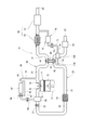
本発明の第1実施形態による排気還流装置は、ディーゼルエンジンシステムに適用される。図1に示すように、排気還流装置10は、内燃機関としてのエンジン本体11、吸気系20、排気系30、過給器40、排気浄化部50、HPL−EGR部60、排気還流部材としてのLPL−EGR部70、及び旋回手段としての旋回部100を備えている。
Embodiments of an exhaust gas recirculation apparatus according to the present invention will be described below with reference to the drawings. Note that, in a plurality of embodiments, substantially the same configuration is denoted by the same reference numeral, and description thereof is omitted.
(First embodiment)
The exhaust gas recirculation apparatus according to the first embodiment of the present invention is applied to a diesel engine system. As shown in FIG. 1, an exhaust
エンジン本体11は、本実施形態ではディーゼルエンジンであり、シリンダ12及びピストン13を有している。シリンダ12とピストン13との間には、燃焼室14が形成される。ピストン13は、シリンダ12の内側を軸方向へ往復移動する。なお、エンジン本体11は、複数のシリンダ12を有しているが、図1においては1つのシリンダ12のみを図示している。エンジン本体11は、後述する吸気通路23と燃焼室14との間を開閉する吸気バルブ15、及び後述する排気通路33と燃焼室14との間を開閉する排気バルブ16を有している。
The
吸気系20は、エンジン本体11に空気を導入する。吸気系20は、吸気通路部材21を有している。吸気通路部材21は、一方の端部に吸気口22を形成し、他方の端部がエンジン本体11に接続している。吸気通路部材21は、吸気口22とエンジン本体11の燃焼室14とを接続する吸気通路23を形成する。吸気通路23の吸気口22の近傍には、空気中の異物を除去するエアクリーナ29が設けられている。また、吸気通路23のエアクリーナ29と後述する過給器のコンプレッサ42との間には、旋回部100が設けられている。旋回部100の詳細については後述する。吸気系20には、吸気口22側から順に、エアクリーナ29、旋回部100、過給器40のコンプレッサ42、インタークーラ24、スロットル25、及び、サージタンク26が設けられている。以下、吸気通路23の吸気の流れは、吸気口22側を上流とし、燃焼室14側を下流とする。
The
スロットル25は、スロットルバルブ27を有している。スロットルバルブ27は、吸気通路23を開閉する。これにより、スロットル25は、HPL−EGR部60を流れる比較的高圧のガスの量をより多くするように調整する。サージタンク26は、スロットル25と燃焼室14との間に設けられている。スロットル25を通過した空気は、サージタンク26を経由してエンジン本体11の各燃焼室14へ分配される。
The
排気系30は、エンジン本体11から排出された排気を外部へ導く。排気系30は、排気通路部材31を有している。排気通路部材31は、一方の端部がエンジン本体11に接続し、他方の端部に排気口32を形成している。排気通路部材31は、エンジン本体11の燃焼室14と排気口32とを接続する排気通路33を形成する。排気系30には、エンジン本体11側から順に、過給器40のタービン41および排気浄化部50が設けられている。以下、排気通路33の排気の流れは、燃焼室14側を上流とし、排気口32側を下流とする。
The
過給器40は、タービン41およびコンプレッサ42を有している。タービン41とコンプレッサ42とは、シャフト43によって連結されている。そのため、タービン41とコンプレッサ42とは、同期して回転する。タービン41は、排気通路33に設けられている。また、コンプレッサ42は、吸気通路23に設けられている。排気通路33を排気が流れることにより、タービン41が回転し、タービン41の回転に伴ってコンプレッサ42が回転する。これにより、吸気通路23を流れる空気は、エンジン本体11の燃焼室14へ過給される。インタークーラ24では、過給器40による過給によって温度が上昇した吸気が冷却される。
The
排気浄化部50は、排気通路33において、過給器40の下流側に設けられる。排気浄化部50は、DPF部51及び触媒部52を有している。DPF部51は、例えばセラミック等によりハニカム状に形成され、排気に含まれる煤等の粒子状物質を捕捉する。触媒部52は、排気中のCO、HC、NOx等を浄化する三元触媒である。
The
HPL−EGR部60は、通路部材61、冷却器62、バイパス通路部材63、開度制御弁64、及び、HPL−EGR弁65を有している。通路部材61は、HPL−EGR通路66を形成している。HPL−EGR通路66は、排気通路33と吸気通路23とを接続している。詳細には、HPL−EGR通路66は、排気系30においてタービン41の上流側で排気通路33から分岐し、吸気系20のスロットル25の下流側で吸気通路23に合流している。そのため、HPL−EGR部60では、エンジン本体11から排出された直後の比較的高圧の排気がHPL−EGRガスとして吸気通路23へ還流される。
The HPL-
冷却器62は、HPL−EGR通路66を流れるHPL−EGRガスを冷却する。バイパス通路部材63は、バイパス通路67を形成している。バイパス通路67は、冷却器62の排気通路33側でHPL−EGR通路66から分岐し、冷却器62の吸気通路23側でHPL−EGR通路66に合流する。冷却器62の吸気通路23側にてHPL−EGR通路66とバイパス通路67とが合流する合流部分には、開度制御弁64が設けられている。開度制御弁64は、冷却器62を経由するHPL−EGR通路66と、冷却器62を経由しないバイパス通路67と、を流れるHPL−EGRガスの流量を制御する。冷却器62を経由するHPL−EGR通路66及び冷却器62を経由しないバイパス通路67を流れるHPL−EGRガスの流量を制御することにより、HPL−EGRガスの温度が制御される。HPL−EGR弁65は、開度制御弁64の吸気通路23側に設けられる。HPL−EGR弁65は、HPL−EGR通路66を開閉することにより、HPL−EGR通路66を経由して排気通路33から吸気通路23へ還流されるHPL−EGRガスの流量を制御する。HPL−EGR弁65が開いているとき、エンジン本体11から排出された排気の一部は、HPL−EGR部60を経由して、HPL−EGRガスとして吸気通路23へ還流される。
The cooler 62 cools the HPL-EGR gas flowing through the HPL-
排気還流部材としてのLPL−EGR部70は、通路部材71、冷却器72、LPL−EGR弁73を有している。通路部材71は、LPL−EGR通路74を形成している。LPL−EGR通路74は、排気通路33と吸気通路23とを接続している。詳細には、LPL−EGR通路74は、排気系30において過給器40の下流側である排気浄化部50のDPF部51と触媒部52との間から分岐し、吸気系20において過給器40のコンプレッサ42の上流側で吸気通路23に合流している。そのため、LPL−EGR部70では、過給器40のタービン41および排気浄化部50のDPF部51を通過した比較的低圧の排気がLPL−EGRガス(以下、単に「EGRガス」という。)として吸気通路23へ還流される。
The LPL-
冷却器72は、LPL−EGR通路74を流れるEGRガスを冷却する。LPL−EGR弁73は、冷却器72の吸気通路23側に設けられる。LPL−EGR弁73は、LPL−EGR通路74を開閉することにより、LPL−EGR通路74を通過して排気通路33から吸気通路23へ還流されるEGRガスの流量を制御する。LPL−EGR弁73が開いているとき、エンジン本体11から排出された排気の一部は、LPL−EGR部70を経由して、EGRガスとして吸気通路23へ還流される。
The cooler 72 cools the EGR gas flowing through the LPL-
旋回手段としての旋回部100は、LPL−EGR通路74と吸気通路23との合流部分またはその下流であって、吸気通路23における過給器40のコンプレッサ42の上流側に設けられている。
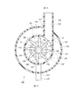
ここで、図2及び図3に基づいて旋回部100について詳述する。なお、図2は、排気流入部を通り、旋回部100の軸に垂直な断面を示す断面図であり、図3は図2のIIIP−O−III線断面に対応する断面図である。
The
Here, the
図2及び図3に示すように、旋回部100は、いずれも樹脂で形成される外筒110及び内筒120を有している。外筒110は、略円筒状に形成され、旋回部100の外郭を構成している。また、外筒110は、吸気系20の吸気通路部材21の一部を構成している。外筒110の上流側の端部には、吸気が流入する吸気流入部111が形成されている。外筒110の下流側の端部には、吸気およびEGRガスが過給器40側へ流出する混合気流出部112が形成されている。外筒110は、混合気流出部112方向に縮径するテーパ部114を有し、混合気流出部112の径は、吸気流入部111の径よりも小さく形成されている。
As shown in FIG.2 and FIG.3, the turning
内筒120は、外筒110の内側に同軸に設けられ、内部に吸気の一部とEGRガスとが旋回する旋回通路151を形成する。また、外筒110と内筒120との間には、旋回させない吸気の通路である非旋回通路152を形成する。
排気流入部133は、内筒120の側面に形成された開口127と接続し、内部に排気流入通路153を形成している。排気流入部133は、内筒120に偏心して設けられる。図2に示すように、排気流入部133は、内筒120の接線方向に設けられる。排気流入部133は、外筒110の側壁115に形成された開口117に挿通される。また、排気流入部133は、開口127と反対側の端部が通路部材71(図2、図3中には不図示)と接続している。これにより、排気流入通路153は、LPL−EGR通路74と接続している。
The
The
内筒120には、混合気流出部112方向に縮径するテーパ部124が形成されている。内筒120の混合気流出部112側の端部には、内筒120の内側にて同軸に設けられる二重管部131が形成されている。この二重管部131と内筒120の内壁126との間には、空間155が形成されている。空間155に連通する位置には、分離部137が設けられる。分離部137は、内筒120の径方向外側に突設される。また、分離部137は、外筒110の側壁115に形成された開口118に挿通され、図1に示す通路部材175を介して過給器40のコンプレッサ42よりも下流側の吸気通路部材21と接続している。分離部137に形成される分離室157は、図示しない開口および通路部材175に形成される通路176を経由してコンプレッサ42の下流側にて吸気通路23と接続している。
The
内筒120の内部には、案内部材140が設けられる。案内部材140は、中心柱141及び8枚のサイクロン羽根142から構成されている。中心柱141は、混合気流出部112側に開口する断面視U字状に形成され、内筒120の軸中心に設けられる。サイクロン羽根142は、中心柱141から内筒120の側壁に向かって放射状に形成される。なお、本形態においては、サイクロン羽根142は8枚であるが、羽根の枚数、形状、傾斜角度や、中心柱141の大きさ、形状等は、EGRガスおよび吸気をどのように旋回させるかに応じて適宜選択することができる。
なお、排気流入部133、二重管部131、分離部137、及び、案内部材140は、内筒120と一体に形成されている。
A
Note that the
ここで旋回部100における吸気およびEGRガスの流れについて図3に基づいて説明する。
矢印A1で示すように、吸気流入部111から流入した吸気のうち、内筒120の流入しなかった吸気である吸気の残部は、外筒110と内筒120との間に形成された非旋回通路152を経由し、旋回することなく混合気流出部112から過給器40のコンプレッサ42側へ供給される。
Here, the flow of the intake air and the EGR gas in the
As indicated by an arrow A1, the remaining portion of the intake air that has not flowed into the
矢印A2で示すように、吸気流入部111から流入した吸気の一部は、内筒120の内部に形成された旋回通路151に流入する。また、矢印Eで示すように、EGRガスは、LPL−EGR通路74から排気流入通路153を経由し、内筒120の内部に形成された旋回通路151に流入する。旋回通路151に流入した吸気およびEGRガスは、サイクロン羽根142によって周方向に導かれて旋回流を形成する。旋回通路151に流入した吸気およびEGRガスは、内筒120内を旋回することにより混合され、温度ムラのない過給用空気となる。過給用空気は、二重管部131の内部を経由して外筒110内に流入し、非旋回通路152を経由した旋回していない吸気とともに混合気流出部112から流出し、過給器40のコンプレッサ42の上流側へ供給される。また、EGRガスがサイクロン羽根142によって旋回流を形成し、内筒120内を吸気の一部とともに旋回し、温度が低下することによって析出した凝縮水やEGRガス中の異物である分離対象物は、遠心分離され、矢印Sで示すように、内筒120の内壁126と二重管部131との間に形成される空間155を旋回した後、分離室157、通路176を経由して、過給器40のコンプレッサ42の下流側の吸気通路23に排出される。なお、分離対象物は、例えば排気浄化部50のDPF部51と触媒部52との間など、他の箇所に排出されるように構成してもよい。
As indicated by an arrow A 2, part of the intake air that has flowed from the intake
以上詳述したように、本実施形態による排気還流装置10は、吸気系20および排気系30を有するエンジン本体11と、過給器40と、LPL−EGR部70と、旋回部100と、を備える。LPL−EGR部70は、排気の一部をタービン41の下流側から、コンプレッサ42の上流側へ導く。旋回部100は、コンプレッサ42の上流側に設けられ、吸気の一部とEGRガスとを旋回させて混合するとともに、排気の温度が低下することにより析出した凝縮水やEGRガス中の異物等である分離対象物を遠心分離する。
As described in detail above, the exhaust
これにより、EGRガスと吸気とが混合されることによってEGRガスの温度が低下して析出する凝縮水およびEGRガス中の分離対象物が遠心分離され、過給器に供給されないので、過給器の破損および腐食等の劣化を抑制することができる。また、旋回部100が、EGRガスと吸気とを混合する機能と、凝縮水を含む異物を分離する機能とを兼ね備えているため、異物等を分離するための手段を別途設ける必要がない。また、吸気の一部とEGRガスとが旋回することにより混合されるので、温度ムラを低減することができる。このような温度ムラのない混合気が過給器に供給されるので、過給器の熱歪による破損および劣化を抑制することができる。さらに、本形態では、吸気の一部は、内筒120の内部に形成される旋回通路151に導かれてEGRガスとともに旋回するが、吸気の残部は、外筒110と内筒120との間に形成された非旋回通路152を経由して旋回することなく過給器40のコンプレッサ42の上流側に供給される。すなわち、吸気の一部のみをEGRガスとともに旋回させているので、吸気の全体を旋回させる場合と比較して、圧損を低減することができる。
As a result, the EGR gas and the intake air are mixed to reduce the temperature of the EGR gas so that the condensed water and the separation target in the EGR gas are centrifuged and not supplied to the supercharger. It is possible to suppress deterioration such as breakage and corrosion. Further, since the
また、外筒110が吸気通路部材21の一部を構成しているので、装置全体の体格を小型化することができる。また、案内部材140により、吸気の一部とEGRガスとが内筒120の周方向に導かれるので、容易に旋回流を形成することができる。
内筒120は、EGRガスが流入する排気流入部133を有し、吸気の一部とEGRガスとを旋回させる旋回通路151を内部に形成する。また、外筒110は、旋回させない吸気の通路である非旋回通路152を内筒120との間に形成する。これにより、外筒110と内筒120とによって旋回通路151と非旋回通路152とを容易に区別することができる。
Moreover, since the
The
排気流入部133は、内筒120の側面に開口し、内筒120に偏心して設けられる。本形態では、排気流入部133は、内筒120の接線方向に設けられる。これにより、内筒120の側面から流入したEGRガスを内筒120の内壁126に沿って容易に旋回させることができる。
案内部材140は、内筒120の内部に形成された旋回通路151に設けられるサイクロン羽根142を有する。これにより、旋回通路151に流入した吸気の一部とEGRガスとを容易に旋回させることができる。
The
The
(第2実施形態)
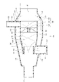
本発明の第2実施形態による旋回部を、図4、図5に示す。なお、排気還流装置全体の構成については、上記第1実施形態と同様であるため、旋回部の構成についてのみ説明する。なお、図4は、排気流入部を通り、旋回部の軸に垂直な断面を示す断面図であり、図5は、図4のV−P−O−V線断面に対応する断面図である。
(Second Embodiment)
A swivel unit according to a second embodiment of the present invention is shown in FIGS. Note that the overall configuration of the exhaust gas recirculation apparatus is the same as that of the first embodiment, and therefore only the configuration of the swivel unit will be described. 4 is a cross-sectional view showing a cross section passing through the exhaust inflow portion and perpendicular to the axis of the swivel portion, and FIG. 5 is a cross-sectional view corresponding to a cross section taken along the line VPOV in FIG. .
本形態の旋回部200は、いずれも樹脂で形成される外筒210及び内筒220を有している。外筒210は、略円筒状に形成され、旋回部200の外郭を形成している。また、外筒210は、吸気系20の吸気通路部材21の一部を構成している。外筒210の上流側の端部には、吸気が流入する吸気流入部211が形成されている。外筒210の吸気流入部211の反対側の端部219には、略円筒状に形成される混合気流出部212が挿通される。混合気流出部212の吸気流入部211側の端部は、ラッパ状に拡開する形状となっている。混合気流出部212の吸気流入部211とは反対側の端部は、過給器40のコンプレッサ42の上流側の吸気通路部材21と接続し、吸気およびEGRガスをコンプレッサ42の上流側の吸気通路23へ供給する。
The
排気流入部233は、外筒210の側壁215に形成された開口217と接続し、内部に排気流入通路253を形成している。排気流入部233は、外筒210に偏心して設けられる。図4に示すように、排気流入部233は、外筒210の接線方向に設けられる。排気流入部233は、開口217と反対側の端部が通路部材71(図4、図5中には不図示)と接続している。これにより、排気流入通路253は、LPL−EGR通路74と接続している。
The
外筒210の内壁216と混合気流出部212との間には、空間255が形成されている。空間255に連通する位置には、分離部237が設けられる。分離部237は、外筒210の径方向外側に突設される。分離部237は、図1に示す通路部材175を介して過給器40のコンプレッサ42よりも下流側の吸気通路部材21と接続している。分離部237に形成される分離室257は、図示しない開口および通路部材175に形成される通路176を経由してコンプレッサ42の下流側にて吸気通路23と接続している。
なお、混合気流出部212、排気流入部233、分離部237は、外筒210と一体に形成されている。
A
The air-fuel
内筒220は、外筒210の内側に同軸に設けられる。内筒220の吸気流入部211側の端部229は、排気流入部233の吸気流入部211側の端部と軸方向における位置が略一致する位置に設けられている。これにより、EGRガスが内筒220内に進入するのを防いでいる。内筒220の内部には、旋回させない吸気の通路である非旋回通路252を形成する。また、外筒210と内筒220との間には、吸気の一部とEGRガスとが旋回する旋回通路251を形成する。内筒220には、混合気流出部212方向に縮径するテーパ部224が形成されている。
The
外筒210と内筒220との間の旋回通路251には、案内部材240が設けられる。案内部材240は、内筒220の外壁228から外筒210の内壁216に向かって放射状に形成されるサイクロン羽根242から構成されている。本形態においては、サイクロン羽根242は8枚であるが、羽根の枚数、形状、傾斜角度等は、EGRガスおよび吸気をどのように旋回させるかに応じて適宜選択することができる。
A
ここで、旋回部200における吸気およびEGRガスの流れについて、図5に基づいて説明する。
矢印B1で示すように、吸気流入部211から流入した吸気のうち、外筒210と内筒220との間に流入しなかった吸気である吸気の残部は、内筒220の内部に形成された非旋回通路252を経由して、旋回することなく混合気流出部212から過給器40のコンプレッサ42側へ供給される。
Here, the flow of the intake air and the EGR gas in the
As indicated by the arrow B1, the remaining portion of the intake air that did not flow between the
矢印B2で示すように、吸気流入部211から流入した吸気の一部は、外筒210と内筒220との間に形成された旋回通路251に流入する。また、矢印Fで示すように、EGRガスは、LPL−EGR通路74から排気流入通路253を経由し、外筒210と内筒120との間に形成された旋回通路251に流入する。旋回通路251に流入した吸気およびEGRガスは、サイクロン羽根242によって周方向に導かれて旋回流を形成する。旋回通路251に流入した吸気およびEGRガスは、外筒210と内筒220との間を旋回することにより混合され、温度ムラのない過給用空気となる。過給用空気は、非旋回通路252を経由した旋回していない吸気とともに混合気流出部212から流出し、過給器40のコンプレッサ42の上流側へ供給される。また、EGRガスがサイクロン羽根242によって旋回流を形成し、外筒210と内筒220との間を吸気の一部とともに旋回し、温度が低下することによって析出した凝縮水やEGRガス中の異物である分離対象物は、遠心分離され、矢印Tで示すように、内壁216と混合気流出部212との間に形成される空間255を旋回した後、分離室257、通路176を経由して、過給器40のコンプレッサ42の下流側の吸気通路23に排出される。なお、分離対象物は、例えば排気浄化部50のDPF部51と触媒部52との間など、他の箇所に排出されるように構成してもよい。
As indicated by an arrow B 2, a part of the intake air that has flowed from the intake
本形態では、コンプレッサ42の上流側に設けられ、吸気の一部とEGRガスとを旋回させて混合するとともに、分離対象物を遠心分離する旋回部200を有している。また、外筒210が吸気通路部材21の一部を構成している。さらに、案内部材により、吸気の一部とEGRガスとが外筒210の周方向に導かれる。これにより、上記実施形態と同様の効果を奏する。
In this embodiment, a
本形態では、EGRガスが流入する排気流入部233が外筒に形成されている。吸気の一部とEGRガスとを旋回させる旋回通路251は、外筒210と内筒220との間に形成される。また、内筒220は、旋回させない吸気の通路である非旋回通路252を内部に形成する。これにより、外筒210と内筒220とによって旋回通路251と非旋回通路252とを容易に区別することができる。
In this embodiment, an
また、排気流入部233は、外筒210の側面に開口し、外筒210に偏心して設けられる。本形態では、排気流入部233は、外筒210の接線方向に設けられる。これにより、外筒210の側面から流入したEGRガスを外筒210の内壁216に沿って容易に旋回させることができる。
案内部材140は、外筒210と内筒220との間に形成された旋回通路251に設けられるサイクロン羽根を有している。これにより、旋回通路251に流入した吸気の一部とEGRガスとを容易に旋回させることができる。
Further, the
The
(他の実施形態)
上記複数の実施形態では、吸気の一部とEGRガスとを旋回させるための案内部材は、サイクロン羽根であったが、吸気の一部とEGRガスとを旋回可能であれば、案内部材はどのような形状であってもよい。例えば、旋回通路が形成される外筒あるいは内筒の側壁に周方向に延びるように突設される壁部であってもよい。また例えば、旋回通路が形成される外筒あるいは内筒の側壁に形成され、旋回通路の一部を拡径するように周方向に延びて形成される溝部であってもよい。
また、外筒と内筒の径や軸方向の長さ等は、旋回させる吸気と旋回させない吸気との割合や、吸気の一部とEGRガスとをどのように旋回させるかに応じて適宜設定することができる。
(Other embodiments)
In the above embodiments, the guide member for turning part of the intake air and the EGR gas is the cyclone blade. However, if the part of the intake air and the EGR gas can be turned, the guide member is Such a shape may be used. For example, the wall part which protrudes so that it may extend in the circumferential direction may be sufficient as the side wall of the outer cylinder or inner cylinder in which a turning path is formed. Further, for example, it may be a groove formed on the side wall of the outer cylinder or the inner cylinder in which the turning passage is formed and extending in the circumferential direction so as to expand a part of the turning passage.
The diameter and axial length of the outer and inner cylinders are appropriately set according to the ratio of the intake air to be turned and the intake air not to be turned and how to turn a part of the intake air and the EGR gas. can do.
上記複数の実施形態では、エンジン本体はディーゼルエンジンであったが、他の実施形態ではガソリンエンジンであってもよい。
上記複数の実施形態では、旋回部は樹脂で形成されていた。他の実施形態では、金属等の他の素材で形成してもよい。
また上記複数の実施形態では、遠心分離された分離対象物は、吸気通路のコンプレッサよりも下流側に排出された。他の実施形態では、遠心分離された対象物を排気通路のタービンよりも下流側、例えばDPF部と触媒部との間、に排出するように構成してもよい。
In the above embodiments, the engine body is a diesel engine, but in other embodiments, a gasoline engine may be used.
In the above embodiments, the swivel portion is made of resin. In other embodiments, other materials such as metal may be used.
In the plurality of embodiments, the separated object to be centrifuged is discharged downstream of the compressor in the intake passage. In another embodiment, the centrifugally separated object may be discharged downstream of the turbine in the exhaust passage, for example, between the DPF part and the catalyst part.
旋回部におけるEGRおよび空気の旋回方向は、コンプレッサに吸入される空気がコンプレッサの効率を高める方向として、コンプレッサの回転方向に対して、正逆どちらでもよい。
以上、本発明は、上記実施形態になんら限定されるものではなく、発明の趣旨を逸脱しない範囲において種々の形態で実施可能である。
The direction of EGR and air swirling in the swirling portion may be either forward or reverse with respect to the rotation direction of the compressor as the direction in which the air sucked into the compressor increases the efficiency of the compressor.
As mentioned above, this invention is not limited to the said embodiment at all, In the range which does not deviate from the meaning of invention, it can implement with a various form.
10:排気還流装置、11:エンジン本体、20:吸気系、30:排気系、40:過給器、41:タービン、42:コンプレッサ、43:シャフト、50:排気浄化部、60:HPL−EGR部、70:LPL−EGR部(排気還流部材)、100:旋回部(旋回手段)、110:外筒、111:吸気流入部、112:混合気流出部、120:内筒、131:二重管部、133:排気流入部、137:分離部、140:案内部材、141:中心柱、142:サイクロン羽根、151:旋回通路、152:非旋回通路、153:排気流入通路、155:空間、157:分離室、175:通路部材、176:通路、200:旋回部(旋回手段)、210:外筒、211:吸気流入部、212:混合気流出部、220:内筒、233:排気流入部、237:分離部、240:案内部材、242:サイクロン羽根、251:旋回通路、252:非旋回通路、253:排気流入通路、255:空間、257:分離室 10: exhaust recirculation device, 11: engine body, 20: intake system, 30: exhaust system, 40: supercharger, 41: turbine, 42: compressor, 43: shaft, 50: exhaust purification unit, 60: HPL-EGR Part, 70: LPL-EGR part (exhaust gas recirculation member), 100: swirl part (swivel means), 110: outer cylinder, 111: intake air inflow part, 112: air mixture outflow part, 120: inner cylinder, 131: double Pipe portion, 133: exhaust inflow portion, 137: separation portion, 140: guide member, 141: central pillar, 142: cyclone blade, 151: swirling passage, 152: non-turning passage, 153: exhaust inflow passage, 155: space, 157: Separation chamber, 175: Passage member, 176: Passage, 200: Swivel part (swivel means), 210: Outer cylinder, 211: Inlet inflow part, 212: Mixture outflow part, 220: Inner cylinder, 233: Exhaust inflow Part, 37: separation unit, 240: guide member 242: Cyclone vanes 251: swirling passage, 252: non-orbiting passage, 253: exhaust inlet passage, 255: space, 257: separation chamber
Claims (8)
前記排気系に設けられるタービン、及び、前記吸気系に設けられ、前記タービンとシャフトによって連結されることにより前記タービンとともに回転するコンプレッサを有し、吸気を過給する過給器と、
前記排気の一部をEGRガスとして前記タービンの下流側から前記コンプレッサの上流側へ導く排気還流部材と、
前記コンプレッサの上流側に設けられ、吸気の一部とEGRガスとを旋回させて混合するとともに、分離対象物を遠心分離する旋回手段と、
を備えることを特徴とする排気還流装置。 An internal combustion engine having an intake system and an exhaust system;
A turbine provided in the exhaust system, and a supercharger provided in the intake system and having a compressor that rotates together with the turbine by being connected to the turbine by a shaft, and supercharges intake air;
An exhaust gas recirculation member for guiding a part of the exhaust gas as EGR gas from the downstream side of the turbine to the upstream side of the compressor;
A swirling means provided on the upstream side of the compressor, swirling and mixing a part of the intake air and the EGR gas, and centrifugally separating the separation object;
An exhaust gas recirculation device comprising:
一方の端部に形成され、吸気が流入する吸気流入部、および、他方の端部に形成され、吸気およびEGRガスが前記過給器側に流出する混合気流出部を有し、前記吸気系の一部を構成する外筒と、
前記外筒の内部に同軸に設けられる内筒と、
前記外筒または前記内筒の周方向に吸気の一部とEGRガスとを導く案内部材と、
を有することを特徴とする請求項1に記載の排気還流装置。 The swivel means is
An intake air inflow portion that is formed at one end and into which the intake air flows, and an air mixture outflow portion that is formed at the other end and through which the intake air and EGR gas flow out to the supercharger side; An outer cylinder constituting a part of
An inner cylinder provided coaxially inside the outer cylinder;
A guide member for guiding part of the intake air and EGR gas in the circumferential direction of the outer cylinder or the inner cylinder;
The exhaust gas recirculation apparatus according to claim 1, comprising:
前記外筒は、旋回させない吸気の通路である非旋回通路を前記内筒との間に形成することを特徴とする請求項2に記載の排気還流装置。 The inner cylinder has an exhaust inflow portion into which EGR gas flows, and forms a swirl passage in which a part of the intake air and the EGR gas swirl,
3. The exhaust gas recirculation apparatus according to claim 2, wherein the outer cylinder forms a non-swirl passage that is an intake passage that is not swirled with the inner cylinder. 4.
前記内筒は、旋回させない吸気の通路である非旋回通路を内部に形成することを特徴とする請求項2に記載の排気還流装置。 The outer cylinder has an exhaust inflow portion through which EGR gas flows, and a swirl passage through which a part of the intake air and the EGR gas swirl is formed between the inner cylinder,
The exhaust gas recirculation apparatus according to claim 2, wherein the inner cylinder forms therein a non-swirl passage that is a passage of intake air that is not swirled.
Priority Applications (1)
| Application Number | Priority Date | Filing Date | Title |
|---|---|---|---|
| JP2009182355A JP5310367B2 (en) | 2009-08-05 | 2009-08-05 | Exhaust gas recirculation device |
Applications Claiming Priority (1)
| Application Number | Priority Date | Filing Date | Title |
|---|---|---|---|
| JP2009182355A JP5310367B2 (en) | 2009-08-05 | 2009-08-05 | Exhaust gas recirculation device |
Publications (2)
| Publication Number | Publication Date |
|---|---|
| JP2011032984A true JP2011032984A (en) | 2011-02-17 |
| JP5310367B2 JP5310367B2 (en) | 2013-10-09 |
Family
ID=43762298
Family Applications (1)
| Application Number | Title | Priority Date | Filing Date |
|---|---|---|---|
| JP2009182355A Expired - Fee Related JP5310367B2 (en) | 2009-08-05 | 2009-08-05 | Exhaust gas recirculation device |
Country Status (1)
| Country | Link |
|---|---|
| JP (1) | JP5310367B2 (en) |
Cited By (6)
| Publication number | Priority date | Publication date | Assignee | Title |
|---|---|---|---|---|
| JP2012202265A (en) * | 2011-03-24 | 2012-10-22 | Toyota Motor Corp | Exhaust gas recirculation device of internal combustion engine |
| JP2013238144A (en) * | 2012-05-14 | 2013-11-28 | Ihi Corp | Low-pressure loop egr device |
| JP2013256912A (en) * | 2012-06-13 | 2013-12-26 | Fuji Heavy Ind Ltd | Filter device of exhaust reflux device |
| JP2014034956A (en) * | 2012-08-10 | 2014-02-24 | Isuzu Motors Ltd | Venturi for exhaust recirculation |
| WO2014170954A1 (en) | 2013-04-16 | 2014-10-23 | トヨタ自動車株式会社 | Compressor for exhaust-gas turbo-supercharger |
| JP7384120B2 (en) | 2020-06-23 | 2023-11-21 | トヨタ紡織株式会社 | Precleaner |
Citations (5)
| Publication number | Priority date | Publication date | Assignee | Title |
|---|---|---|---|---|
| JPH09303213A (en) * | 1996-05-13 | 1997-11-25 | Mitsubishi Heavy Ind Ltd | Exhaust recirculation device for internal combustion engine |
| JP2000018108A (en) * | 1998-07-02 | 2000-01-18 | Toyota Motor Corp | Intake system of internal combustion engine |
| JP2009024692A (en) * | 2007-06-21 | 2009-02-05 | Toyota Motor Corp | Exhaust gas recirculation device of internal combustion engine |
| JP2009041551A (en) * | 2007-08-13 | 2009-02-26 | Toyota Motor Corp | Exhaust gas recirculation device for internal combustion engine |
| JP2009108716A (en) * | 2007-10-29 | 2009-05-21 | Toyota Motor Corp | Foreign matter removal device for internal combustion engine |
-
2009
- 2009-08-05 JP JP2009182355A patent/JP5310367B2/en not_active Expired - Fee Related
Patent Citations (5)
| Publication number | Priority date | Publication date | Assignee | Title |
|---|---|---|---|---|
| JPH09303213A (en) * | 1996-05-13 | 1997-11-25 | Mitsubishi Heavy Ind Ltd | Exhaust recirculation device for internal combustion engine |
| JP2000018108A (en) * | 1998-07-02 | 2000-01-18 | Toyota Motor Corp | Intake system of internal combustion engine |
| JP2009024692A (en) * | 2007-06-21 | 2009-02-05 | Toyota Motor Corp | Exhaust gas recirculation device of internal combustion engine |
| JP2009041551A (en) * | 2007-08-13 | 2009-02-26 | Toyota Motor Corp | Exhaust gas recirculation device for internal combustion engine |
| JP2009108716A (en) * | 2007-10-29 | 2009-05-21 | Toyota Motor Corp | Foreign matter removal device for internal combustion engine |
Cited By (7)
| Publication number | Priority date | Publication date | Assignee | Title |
|---|---|---|---|---|
| JP2012202265A (en) * | 2011-03-24 | 2012-10-22 | Toyota Motor Corp | Exhaust gas recirculation device of internal combustion engine |
| JP2013238144A (en) * | 2012-05-14 | 2013-11-28 | Ihi Corp | Low-pressure loop egr device |
| JP2013256912A (en) * | 2012-06-13 | 2013-12-26 | Fuji Heavy Ind Ltd | Filter device of exhaust reflux device |
| JP2014034956A (en) * | 2012-08-10 | 2014-02-24 | Isuzu Motors Ltd | Venturi for exhaust recirculation |
| WO2014170954A1 (en) | 2013-04-16 | 2014-10-23 | トヨタ自動車株式会社 | Compressor for exhaust-gas turbo-supercharger |
| US10329999B2 (en) | 2013-04-16 | 2019-06-25 | Toyota Jidosha Kabushiki Kaisha | Compressor of exhaust turbocharger |
| JP7384120B2 (en) | 2020-06-23 | 2023-11-21 | トヨタ紡織株式会社 | Precleaner |
Also Published As
| Publication number | Publication date |
|---|---|
| JP5310367B2 (en) | 2013-10-09 |
Similar Documents
| Publication | Publication Date | Title |
|---|---|---|
| US20140208744A1 (en) | Egr apparatus for internal combustion engine | |
| JP5047352B2 (en) | Exhaust turbocharger housing structure | |
| CN107795413B (en) | System and method for exhaust gas recirculation mixer | |
| US7343742B2 (en) | Exhaust turbocharger | |
| JP5310367B2 (en) | Exhaust gas recirculation device | |
| JP5813017B2 (en) | Turbocharger | |
| JP5747483B2 (en) | Low pressure loop EGR device | |
| US20110011084A1 (en) | Exhaust gas recirculation system for internal combustion engine | |
| CN106460533B (en) | For save fuel and via asymmetric double spiral case exhaust gas recycling optimization pulse power separation double volute turbocharger | |
| JP2011220127A (en) | Exhaust gas circulation device | |
| US20130152582A1 (en) | Compressor recirculation into annular volume | |
| JP2016104977A (en) | Exhaust gas circulation device of internal combustion engine | |
| KR20160083964A (en) | Compressor of an exhaust-gas turbocharger | |
| US9951723B2 (en) | Turbocharging system for use with internal combustion engine | |
| JP2011021561A (en) | Exhaust gas recirculation device for internal combustion engine | |
| JP5729112B2 (en) | Supercharger for internal combustion engine | |
| WO2017169982A1 (en) | Engine with turbo supercharger | |
| JP2010077833A (en) | Exhaust gas recirculation system | |
| JP6119110B2 (en) | Low pressure loop EGR device | |
| EP2322787B1 (en) | Exhaust gas recirculation system | |
| JP2011038453A (en) | Mixing device | |
| JP2011027033A (en) | Exhaust gas recirculation device | |
| US8479510B2 (en) | Exhaust gas recirculation system | |
| JP2010071127A (en) | Air supply device for engine with egr device | |
| JP2022076179A (en) | Centrifugal compressor, turbocharger, and engine system |
Legal Events
| Date | Code | Title | Description |
|---|---|---|---|
| A621 | Written request for application examination |
Free format text: JAPANESE INTERMEDIATE CODE: A621 Effective date: 20120224 |
|
| A977 | Report on retrieval |
Free format text: JAPANESE INTERMEDIATE CODE: A971007 Effective date: 20121217 |
|
| A131 | Notification of reasons for refusal |
Free format text: JAPANESE INTERMEDIATE CODE: A131 Effective date: 20121221 |
|
| A521 | Written amendment |
Free format text: JAPANESE INTERMEDIATE CODE: A523 Effective date: 20130123 |
|
| TRDD | Decision of grant or rejection written | ||
| A01 | Written decision to grant a patent or to grant a registration (utility model) |
Free format text: JAPANESE INTERMEDIATE CODE: A01 Effective date: 20130604 |
|
| A61 | First payment of annual fees (during grant procedure) |
Free format text: JAPANESE INTERMEDIATE CODE: A61 Effective date: 20130617 |
|
| LAPS | Cancellation because of no payment of annual fees |