JP2011027162A - Bearing of universal joint - Google Patents
Bearing of universal joint Download PDFInfo
- Publication number
- JP2011027162A JP2011027162A JP2009172722A JP2009172722A JP2011027162A JP 2011027162 A JP2011027162 A JP 2011027162A JP 2009172722 A JP2009172722 A JP 2009172722A JP 2009172722 A JP2009172722 A JP 2009172722A JP 2011027162 A JP2011027162 A JP 2011027162A
- Authority
- JP
- Japan
- Prior art keywords
- roller
- roller shafts
- shaft
- bearing
- shafts
- Prior art date
- Legal status (The legal status is an assumption and is not a legal conclusion. Google has not performed a legal analysis and makes no representation as to the accuracy of the status listed.)
- Pending
Links
Images


Landscapes
- Rolling Contact Bearings (AREA)
Abstract
Description
本発明は、自在継手の軸受に係り、特に、十字軸のコロ軸受の構造に関するものである。 The present invention relates to a universal joint bearing, and more particularly to the structure of a cross shaft roller bearing.
従来一般的な自在継手の十字軸においては、4方向に突出する軸部に、複数列にコロが並設された構造の軸受がそれぞれ設けられており、各軸にそれぞれ油孔が穿設されて、全油孔に対して軸受潤滑用の潤滑油、例えば、グリースが給油される構成になっている(例えば、特許文献1,2参照)。 Conventional cross joints of universal joints are provided with bearings having a structure in which rollers are arranged in parallel in a plurality of rows on shafts protruding in four directions, and oil holes are formed in the respective shafts. Thus, lubricating oil for bearing lubrication, for example, grease is supplied to all the oil holes (see, for example, Patent Documents 1 and 2).
図3は従来の自在継手の十字軸の一部断面図である。 FIG. 3 is a partial cross-sectional view of a cross shaft of a conventional universal joint.
図3において、十字軸100は、互いに垂直な方向に基部101から突出する4本の軸部102が設けられており、各軸部102の先端部に軸受103がそれぞれ設けられている。軸受103の内側と軸部102の外側間には上下複数列(本例では上下2列のものを示している)のコロ軸104が介在し、軸受103の軸部102の外側に対して軸受103の周方向への回転を可能にしている。
In FIG. 3, the
前記各軸部102には、断面十字状に油孔105が基部101を通って貫通している。油孔105は基部101の中心部を通り、一方の軸部102から他方の軸部102へ延在するように形成されている。
Each
各油孔105の軸受103側には、軸受103の外部に一部が突出するように給油部106がそれぞれ設けられている。この給油部106から対応する油孔105へ潤滑油が給油される。
前記構成の十字軸100において、各給油部106から油孔105へ潤滑油が給油された後、各給油部106の開口は閉鎖される。
In the
そして、自在継手の動作時には、各油孔105内の潤滑油が軸受103の天板部103a部分を通って、各コロ軸104部分へ達することにより、円滑な継手動作が行われるようになっている。
During the operation of the universal joint, the lubricating oil in each
そして、従来の一般的な十字軸の軸受103は、図3に示すように、軸受103の内側と軸部102の外側間に上下複数列(本例では上下2列のものを示している)のコロ軸104が配され、さらにコロ軸104の複数個が、図4に示す軸受部分の平面断面図のように、軸受103の内側と軸部102の外側間の周囲に互いに密接するように並設されている構成のものである。
As shown in FIG. 3, the conventional general cross shaft bearing 103 has a plurality of upper and lower rows between the inside of the
自在継手の十字軸は、各種機器に設けられて構造上、多方面からの負荷を受けるものである。そのため軸受103では激しい回転運動および摺動運動が行われ、コロ軸に供給されるグリースなどの潤滑油の不足による潤滑低下、あるいはコロ軸の焼付けが生じやすく、さらに、コロ軸の摩損による軸受の耐久性の低下などに対応することが問題である。
The cross shaft of the universal joint is provided in various devices and receives a load from various directions due to its structure. For this reason, the
そこで、本発明者らは、この種の十字軸における軸受について検討し、鋭意研究した結果、下記のような技術課題を見出した。 Therefore, the present inventors have studied the bearings on this type of cross shaft and conducted extensive research, and as a result, have found the following technical problems.
図5は従来の十字軸における軸受のコロ軸を展開して示す配列図であって、各コロ軸104は軸方向の長さが全て同じであり、これらのコロ軸104が並設された状態では、コロ軸104の端面104aの配置位置が、コロ軸104の径方向(周方向)で一致し、コロ軸104の端部に形成されている面取部104bの位置も一致している。
FIG. 5 is an array diagram showing the developed roller shafts of the conventional cross shaft. The
このため、図5に示すように、隣接するコロ軸104における各面取部104bの位置が合致して、この部位が潤滑油の溜まる隙間(油溜)Aとなる。
For this reason, as shown in FIG. 5, the positions of the
通常、潤滑油は、コロ軸104の端面104a側からコロ軸104間の側面へと流れ、コロ軸104間の油溜Aにて溜り、さらに、隣接するコロ軸104の端面104aと側面とに流れ、潤滑油がコロ軸104全体に行き渡るようにして潤滑作用が行われる。
Normally, the lubricating oil flows from the
しかし、従来において、油溜Aは、コロ軸104の上下方向において同一位置に存在する。よって、油溜Aからコロ軸104の側面を潤滑油が流れるが、油溜Aからコロ軸104の全側面に行き渡る距離が長く、時として、潤滑油がコロ軸104の全側面に行き渡らず、これにより潤滑油不足が生じて、コロ軸受の焼付けの原因となる。
However, conventionally, the oil reservoir A exists at the same position in the vertical direction of the
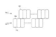
また、十字軸部分の摺動方向に偏荷重が加わって、上下のコロ軸列に対する負荷が異なると、コロ軸104の端面104aの位置が、コロ軸104の周方向において同じであるため、場合によって、図6に示すように、上段のコロ軸列104−1と下段のコロ軸列104−2間に相対的に滑り移動が生じ、上下段のコロ軸列104−1,104−2に動作の偏りが発生する。
In addition, when an eccentric load is applied in the sliding direction of the cross shaft portion and the load on the upper and lower roller shaft rows is different, the position of the
これはコロ軸104の端面104aの配置位置が横方向で一致しているため、潤滑油がコロ軸104の側面からコロ軸104の端面104aへと回り込みやすくなり、上下接合するコロ軸104の端面104aどうしで相対的摺動が生じやくなることにより発生する。
This is because the arrangement position of the
このことは、上下のコロ軸104において摩耗に差が生じることになり、動作の安定性を低下させ、軸受寿命を短くする原因となる。
This causes a difference in wear between the upper and
さらに、前記のように上下接合するコロ軸104の端面104aどうしで相対的摺動が生じる際、各コロ軸104における移動量は全て同じにはならず、移動抵抗に差があると、同じ列の隣接するコロ軸104間に隙間Cが生じてしまう。そして、図7に示すように、前記隙間にてコロ軸104’の倒れを生じさせてしまうことがある。
Furthermore, when relative sliding occurs between the
これらの現象は、軸受103の動作不良を生じさせる原因となり、軸受動作の安定性に問題であると共に、一部のコロ軸に過負荷が加わることになり、軸受寿命を短くする原因となる。
These phenomena cause a malfunction of the
そこで、本発明は、前記従来技術の課題を解決し、簡単な構成により、コロ軸全体に潤滑油が円滑に行き渡り、複数列のコロ軸において列ごとの相対移動を防ぎ、コロ軸の焼き付きや摩損の発生を防止し、安定した動作を長期に渡って維持させることにより、耐久性を向上させて、長寿命化を図るようにした自在継手の軸受を提供することを目的とする。 Therefore, the present invention solves the above-mentioned problems of the prior art, and with a simple configuration, the lubricating oil spreads smoothly over the entire roller shaft, preventing relative movement for each row in the plurality of roller shafts. An object of the present invention is to provide a universal joint bearing that prevents the occurrence of wear and maintains a stable operation over a long period of time, thereby improving durability and extending the service life.
前記目的を解決するため、請求項1に記載の発明は、基部に対して4方向に突出する軸部の先端部にそれぞれ設けられ、各軸受に対し前記各軸部に設けられた油孔を通して潤滑油が供給される構成の自在継手の軸受において、軸受本体の内周部と前記軸部の外周部との間に上下複数列にコロ軸を配し、該コロ軸を前記軸受本体の内周部と前記軸部の外周部との間に互いに密接して並設し、かつ隣接するコロ軸において同径で軸方向の長さが異なるコロ軸を組み合わせて配設してなることを特徴とし、この構成によって、隣接する各コロ軸において上下のコロ軸における端面位置が異なり、しかも、端面の周部にて形成される隙間(油溜)が隣り合うコロ軸の側部途中に位置することになり、隣り合うコロ軸が互いに移動を規制し合うことになる。さらに、油溜が各コロ軸の側部途中に位置するため、潤滑油がコロ軸全体に回り込みやすくなる。 In order to solve the above-mentioned object, the invention according to claim 1 is provided at a tip portion of a shaft portion protruding in four directions with respect to a base portion, and through an oil hole provided in each shaft portion with respect to each bearing. In a universal joint bearing configured to be supplied with lubricating oil, roller shafts are arranged in a plurality of upper and lower rows between the inner peripheral portion of the bearing body and the outer peripheral portion of the shaft portion, and the roller shafts are arranged inside the bearing main body. The roller shafts are arranged in close proximity to each other between the peripheral portion and the outer peripheral portion of the shaft portion, and roller rollers having the same diameter and different axial lengths are arranged in combination in adjacent roller shafts. With this configuration, the end surface positions of the upper and lower roller shafts in each adjacent roller shaft are different, and a gap (oil reservoir) formed in the peripheral portion of the end surface is located in the middle of the side portion of the adjacent roller shaft. As a result, the adjacent roller shafts regulate the movement of each other. . Furthermore, since the oil reservoir is located in the middle of the side portion of each roller shaft, the lubricating oil easily flows around the entire roller shaft.
請求項2に記載の発明は、請求項1記載の自在継手の軸受において、長さの異なるコロ軸を交互に配設したことを特徴とし、この構成によって、コロ軸は軸方向と軸方向に直交する方向にコロ軸の端面位置,油溜位置が交互に配置されることになる。 According to a second aspect of the present invention, in the universal joint bearing according to the first aspect, the roller shafts having different lengths are alternately arranged. With this configuration, the roller shafts are arranged in the axial direction and the axial direction. The end face position of the roller shaft and the oil reservoir position are alternately arranged in the orthogonal direction.
請求項3に記載の発明は、請求項1または2記載の自在継手の軸受において、長さの異なるコロ軸の組み合せは、上下において長軸と短軸との組合せであり、かつ長軸と短軸ごとに長さが同じであることを特徴とし、コロ軸の種類を増やさずに、長さの異なるコロ軸の組み合せを実現できる。 According to a third aspect of the present invention, in the universal joint bearing according to the first or second aspect, the combination of the roller shafts having different lengths is a combination of the long shaft and the short shaft in the vertical direction, and the long shaft and the short shaft. It is characterized in that the lengths are the same for each shaft, and a combination of roller shafts having different lengths can be realized without increasing the types of roller shafts.
請求項4に記載の発明は、請求項1〜3いずれか1項記載の自在継手の軸受において、コロ軸は端面周囲に面取部が形成されていることを特徴とし、この構成によって、面取部間において油溜が確実に形成される。 According to a fourth aspect of the present invention, in the universal joint bearing according to any one of the first to third aspects, the roller shaft has a chamfered portion formed around the end surface. An oil sump is reliably formed between the catches.
本発明の自在継手の軸受によれば、隣接する各コロ軸において上下のコロ軸における端面位置が異なり、しかも、端面の周部にて形成される隙間(油溜)を、隣り合うコロ軸の側部中央部分に位置させることができるため、従来に比べてコロ軸の側部に潤滑油が達する距離が短くなり、潤滑油がコロ軸全体に回り込みやすくなって、コロ軸全体に潤滑油が円滑に行き渡りやすくなる。また、従来のようにコロ軸の端面位置が一致せず、隣り合うコロ軸が互いに移動を規制し合うことになるため、コロ軸において列ごとの相対移動がなくなる。 According to the universal joint bearing of the present invention, the positions of the end surfaces of the upper and lower roller shafts of the adjacent roller shafts are different, and the gap (oil reservoir) formed in the peripheral portion of the end surface is changed between the adjacent roller shafts. Since it can be positioned at the center of the side, the distance that the lubricant reaches the side of the roller shaft is shorter than before, making it easier for the lubricant to wrap around the entire roller shaft. It becomes easy to spread smoothly. In addition, since the end face positions of the roller shafts do not coincide with each other and the adjacent roller shafts restrict the movement of each other, the relative movement of each row in the roller shafts is eliminated.
よって、本発明によれば、コロ軸の焼き付きや摩損の発生を防止して、安定した動作が長期に渡って維持され、耐久性を向上させ,長寿命化を図ることができる自在継手の軸受が実現する。 Therefore, according to the present invention, a universal joint bearing that prevents seizure of the roller shaft and occurrence of wear, maintains a stable operation for a long period of time, improves durability, and extends the service life. Is realized.
以下、本発明の実施の形態について、図面に基づいて説明する。 Hereinafter, embodiments of the present invention will be described with reference to the drawings.
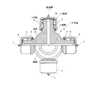
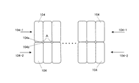
図1は本発明に係る自在継手における十字軸の実施形態の一部断面図、図2は本実施形態の十字軸における軸受のコロ軸を展開して示す配列図である。 FIG. 1 is a partial cross-sectional view of an embodiment of a cruciform shaft in a universal joint according to the present invention, and FIG. 2 is an arrangement view showing a roller shaft of a bearing in the cruciform shaft of the present embodiment.
図1において、十字軸1は、互いに垂直な方向に基部2から突出する4本の軸部3が設けられており、各軸部3の先端部に軸受4がそれぞれ設けられている。軸受4の内側と軸部3の外側間には上下複数列(本例では上下2列のものを示している)のコロ軸5が介在し、軸受4の軸部3の外側に対して軸受4の周方向への回転を可能にしている。
In FIG. 1, the cross shaft 1 is provided with four
前記各軸部3には、断面十字状に油孔6が基部2を通って貫通している。油孔6は基部2の中心部を通り、一方の軸部3から他方の軸部3へ延在するように形成されている。
Each
各油孔6の軸受4側には、軸受4の外部に一部が突出するように給油部7がそれぞれ設けられている。この給油部7から対応する油孔6へ潤滑油が給油される。
An
前記構成の十字軸1において、各給油部7から油孔6へ潤滑油が給油された後、各給油部7は閉鎖される。そして、自在継手の動作時には、各油孔6内の潤滑油が、軸受4の天板部4a部分を通って、各コロ軸5部分へ達することにより、円滑な継手動作が行われるようになっている。
In the cross shaft 1 configured as described above, after the lubricating oil is supplied from the
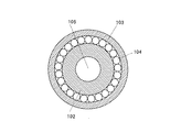
そして、軸受4は、軸受4の内側と軸部3外側間に上下複数列(本例では上下2列のものを示している)のコロ軸5が配され、さらにコロ軸5の複数個が、図4に示すように、平面状態では、軸受4の内側と軸部3の外側間の周囲に互いに密接するように並設されている構成のものである。
In the
本実施形態の前記構成は、基本的には図3に示す自在継手と同様な構成であるが、軸受4の内部構成が異なる。
The configuration of the present embodiment is basically the same as the universal joint shown in FIG. 3, but the internal configuration of the
すなわち、本実施形態では、軸受4のコロ軸5は、全て同径であるが、上下および隣り合うコロ軸5において、それぞれその長さが異なるコロ軸を組み合わせて配設している点が、図3に示す軸受103の構成とは異なる。
That is, in this embodiment, all the
図2において、上段のコロ軸列5−1では短いコロ軸50と長いコロ軸51とが交互に配され、これらの長短のコロ軸50,51に対応して、下段のコロ軸列5−2に短いコロ軸50と長いコロ軸51とを交互に配設する。
In FIG. 2,
すなわち、本例では、下段のコロ軸列5−2において、上段のコロ軸列5−1の短いコロ軸50に対応させて長いコロ軸51が配され、かつ上段のコロ軸列5−1の長いコロ軸51に対応させて短いコロ軸50が配されている。
That is, in this example, in the lower roller shaft row 5-2, a
このため、隣接する各コロ軸50,51において、上下と横方向のコロ軸50,51における端面50a,51aの接合位置が異なり、しかも、端面50a,51aの周部に形成された面取部50b,51bにて形成される隙間(油溜)Aが、隣接する長いコロ軸51の側部途中(本例では略中間位置)に位置することになる。
For this reason, in each
よって、本実施形態では、コロ軸50,51における端面50a,51aの接合位置が異なり、従来例のように一直線上にないため、コロ軸50,51の径方向(周方向)において隣り合うコロ軸50,51が、互いに移動を規制し合うことになる。さらに、油溜Aが各長いコロ軸51の中間部に位置するため、長いコロ軸51であっても潤滑油が全体に回り込みやすくなる。
Therefore, in this embodiment, the joining positions of the end faces 50a and 51a on the
したがって、本実施形態では、軸受4において、長さに長短の差があるコロ軸50,51を用いて、これらのコロ軸50,51を、交互に前記のように互い違いになるように配列したことにより、コロ軸50,51における端面50a,51aの周部により形成される油溜Aとなる隙間が、図4に示す従来構造に比して多くなるため、コロ接触面に潤滑油が常に供給される状態になり、従来よりも潤滑油による潤滑性が向上する。
Therefore, in this embodiment, in the
また、本実施形態では、上段のコロ軸列5−1と下段のコロ軸列5−2との端面において、図6に示す従来のような滑りが発生せず、しかも、図7に示すようなコロ軸間に隙間が生じて、コロ軸が倒れるなどの動きの偏りが起きない。したがって、各コロ軸が円滑に動作して、特定のコロ軸が摩耗することがない。よって、軸受寿命を向上させることができる。 Further, in the present embodiment, the slippage unlike the conventional case shown in FIG. 6 does not occur on the end surfaces of the upper roller shaft row 5-1 and the lower roller shaft row 5-2, and as shown in FIG. There is no gap in the movement between the roller shafts, such as a gap between them and the roller shafts falling down. Therefore, each roller shaft operates smoothly, and a specific roller shaft does not wear. Therefore, the bearing life can be improved.
さらに、本実施形態では、前記油溜Aが多くなったことと、および上段と下段とのコロ軸において動きの偏りがなくなったことにより、潤滑性とコロ軸の運動とが改善されるため、十字軸継手の転動面および軸受の焼付けの発生や、十字軸継手の転動面の剥離などの不具合の発生を防止することができる。 Furthermore, in this embodiment, the lubricity and the motion of the roller shaft are improved due to the increase in the oil sump A and the elimination of the motion bias in the upper and lower roller shafts. Occurrence of defects such as seizure of the rolling surface and bearing of the cross shaft joint and peeling of the rolling surface of the cross shaft joint can be prevented.
なお、コロ軸50,51の長さ、および軸線方向の個数は、軸線方向における全コロ軸の長さを加算した全長が同じであれば、特定されるものでなく、各コロ軸の長短の長さ、およびコロ軸の軸方向の個数は任意に設定してよい。
The length of the
ただし、短いコロ軸50の長さを全て一定に設定し、かつ長いコロ軸51の長さも全て一定に設定することにより、コロ軸の種類を増やさずに、最も簡単に前記配置構成にすることができる。
However, by setting all the lengths of the
また、本実施形態では、コロ軸列は軸方向に上下2段の例を示したが、コロ軸列の段数は2列以上であれば特に限定されない。 Further, in this embodiment, the example of the roller shaft row having two upper and lower stages in the axial direction is shown, but the number of roller shaft rows is not particularly limited as long as it is two or more.
本発明は、車両や圧延機など各種機器において使用される自在継手全てに適用され、特に、安定して動作し、かつ耐久性を備えた軸受を具備する十字軸であるため、各種機器の連結継手部分に実施可能である。 The present invention is applicable to all universal joints used in various devices such as vehicles and rolling mills, and is a cross shaft having a bearing that operates stably and has durability. It can be applied to the joint part.
1 十字軸
2 基部
3 軸部
4 軸受
5 コロ軸
5−1 上段のコロ軸列
5−2 下段のコロ軸列
50 短いコロ軸
51 長いコロ軸
50a,51a 端面
50b,51b 面取部
6 油孔
7 給油部
A 隙間(油溜)
DESCRIPTION OF SYMBOLS 1
Claims (4)
軸受本体の内周部と前記軸部の外周部との間に上下複数列にコロ軸を配し、該コロ軸を前記軸受本体の内周部と前記軸部の外周部との間に互いに密接して並設し、かつ隣接するコロ軸において同径で軸方向の長さが異なるコロ軸を組み合わせて配設してなることを特徴とする自在継手の軸受。 In a universal joint bearing provided at a tip portion of a shaft portion projecting in four directions with respect to a base portion and configured to supply lubricating oil to each bearing through an oil hole provided in each shaft portion,
Roller shafts are arranged in upper and lower rows between the inner peripheral part of the bearing body and the outer peripheral part of the shaft part, and the roller shafts are mutually connected between the inner peripheral part of the bearing body and the outer peripheral part of the shaft part. A universal joint bearing comprising a plurality of roller shafts arranged in close contact with each other and having the same diameter and different axial lengths in adjacent roller shafts.
Priority Applications (1)
| Application Number | Priority Date | Filing Date | Title |
|---|---|---|---|
| JP2009172722A JP2011027162A (en) | 2009-07-24 | 2009-07-24 | Bearing of universal joint |
Applications Claiming Priority (1)
| Application Number | Priority Date | Filing Date | Title |
|---|---|---|---|
| JP2009172722A JP2011027162A (en) | 2009-07-24 | 2009-07-24 | Bearing of universal joint |
Publications (1)
| Publication Number | Publication Date |
|---|---|
| JP2011027162A true JP2011027162A (en) | 2011-02-10 |
Family
ID=43636146
Family Applications (1)
| Application Number | Title | Priority Date | Filing Date |
|---|---|---|---|
| JP2009172722A Pending JP2011027162A (en) | 2009-07-24 | 2009-07-24 | Bearing of universal joint |
Country Status (1)
| Country | Link |
|---|---|
| JP (1) | JP2011027162A (en) |
Cited By (3)
| Publication number | Priority date | Publication date | Assignee | Title |
|---|---|---|---|---|
| JP2015055265A (en) * | 2013-09-10 | 2015-03-23 | Ntn株式会社 | Double-row roller bearing |
| WO2017030018A1 (en) * | 2015-08-17 | 2017-02-23 | Ntn株式会社 | Cylindrical roller bearing |
| CN115111275A (en) * | 2022-08-29 | 2022-09-27 | 万向钱潮股份公司 | Universal joint roller bearing |
Citations (2)
| Publication number | Priority date | Publication date | Assignee | Title |
|---|---|---|---|---|
| JPS5985424U (en) * | 1982-11-30 | 1984-06-09 | 株式会社中村自工 | Bearing device for universal joints |
| JPS61161423U (en) * | 1985-03-28 | 1986-10-06 |
-
2009
- 2009-07-24 JP JP2009172722A patent/JP2011027162A/en active Pending
Patent Citations (2)
| Publication number | Priority date | Publication date | Assignee | Title |
|---|---|---|---|---|
| JPS5985424U (en) * | 1982-11-30 | 1984-06-09 | 株式会社中村自工 | Bearing device for universal joints |
| JPS61161423U (en) * | 1985-03-28 | 1986-10-06 |
Cited By (3)
| Publication number | Priority date | Publication date | Assignee | Title |
|---|---|---|---|---|
| JP2015055265A (en) * | 2013-09-10 | 2015-03-23 | Ntn株式会社 | Double-row roller bearing |
| WO2017030018A1 (en) * | 2015-08-17 | 2017-02-23 | Ntn株式会社 | Cylindrical roller bearing |
| CN115111275A (en) * | 2022-08-29 | 2022-09-27 | 万向钱潮股份公司 | Universal joint roller bearing |
Similar Documents
| Publication | Publication Date | Title |
|---|---|---|
| US8616776B2 (en) | Cylindrical roller bearing | |
| US8998498B2 (en) | Tapered roller bearing and manufacturing method for retainer of tapered roller bearing | |
| CN100572836C (en) | Tapered roller bearing with filter cage | |
| US9004269B2 (en) | Conveyor chain | |
| JP2012041940A (en) | Retainer of cylindrical roller bearing and cylindrical roller bearing | |
| WO2010122904A1 (en) | Needle bearing and needle bearing device | |
| JP2011027162A (en) | Bearing of universal joint | |
| US20090175569A1 (en) | Bearing apparatus | |
| JP2007032612A (en) | Roller bearing | |
| JP5095630B2 (en) | Bearing race | |
| JP2011252543A (en) | Rolling bearing | |
| JP5889596B2 (en) | Roller bearing | |
| JP2001027249A (en) | Bearing retainer and rolling bearing | |
| JP2003120683A (en) | Thrust roller bearing | |
| WO2021177369A1 (en) | Retainer for radial roller bearing, and radial roller bearing | |
| US10145413B2 (en) | Combination bearing | |
| JP2009092162A (en) | Roller bearing | |
| JP2007327518A (en) | Cylindrical roller bearing and its cage | |
| JP5363304B2 (en) | Full complement cylindrical roller bearings | |
| JP2009168106A (en) | Roller bearing and its fixing structure | |
| JP2010116107A (en) | Axle device for railway vehicle | |
| JP5933041B2 (en) | Bearing assembly for connecting rod | |
| JP6106830B2 (en) | Rolling bearing and method of using the same | |
| JP2010249213A (en) | Ball bearing | |
| TWI458896B (en) | Separation cross roller bearing |
Legal Events
| Date | Code | Title | Description |
|---|---|---|---|
| A621 | Written request for application examination |
Free format text: JAPANESE INTERMEDIATE CODE: A621 Effective date: 20120611 |
|
| A977 | Report on retrieval |
Free format text: JAPANESE INTERMEDIATE CODE: A971007 Effective date: 20121227 |
|
| A131 | Notification of reasons for refusal |
Free format text: JAPANESE INTERMEDIATE CODE: A131 Effective date: 20130708 |
|
| A02 | Decision of refusal |
Effective date: 20131105 Free format text: JAPANESE INTERMEDIATE CODE: A02 |