JP2011026859A - Installation structure for extended member, installation construction method therefor, fitting structure for external installation member using the same, and repairing structure - Google Patents
Installation structure for extended member, installation construction method therefor, fitting structure for external installation member using the same, and repairing structure Download PDFInfo
- Publication number
- JP2011026859A JP2011026859A JP2009174335A JP2009174335A JP2011026859A JP 2011026859 A JP2011026859 A JP 2011026859A JP 2009174335 A JP2009174335 A JP 2009174335A JP 2009174335 A JP2009174335 A JP 2009174335A JP 2011026859 A JP2011026859 A JP 2011026859A
- Authority
- JP
- Japan
- Prior art keywords
- installation
- roof
- attached
- vertical
- fixed
- Prior art date
- Legal status (The legal status is an assumption and is not a legal conclusion. Google has not performed a legal analysis and makes no representation as to the accuracy of the status listed.)
- Pending
Links
Images


Abstract
Description
本発明は、建築物の屋根の種類にかかわらずに任意の位置に太陽電池システムや雪止め金具等の外設部材を取り付けることができ、さらには屋根の改修にも適用できる持出部材の設置構造、その設置施工方法、及びそれを用いた外設部材の取付構造、改修構造に関する。 The present invention can attach an external member such as a solar cell system or a snow stop fitting to an arbitrary position regardless of the type of roof of the building, and further, installation of a take-out member applicable to roof repair The present invention relates to a structure, an installation method thereof, an external member mounting structure using the structure, and a repair structure.
従来、横葺き屋根や縦葺き屋根などの上に太陽電池システム等を取り付ける場合には、大別して屋根材自体に太陽電池パネルを一体的に組み込む方法と、屋根面に支持架台などの取付部材を固定してその上に太陽電池システムを構築する方法とが知られている。 Conventionally, when a solar cell system or the like is mounted on a horizontal roof or a vertical roof, a method of incorporating a solar cell panel into the roof material itself and an attachment member such as a support frame on the roof surface. A method of fixing and building a solar cell system thereon is known.
前記屋根材自体に太陽電池パネルを一体的に組み込む方法は、屋根材を製造する技術と太陽電池パネルを製造する技術とが必要であり、様々な仕様の建物(屋根)に適用することは到底困難であった。 The method of integrating the solar cell panel into the roof material itself requires a technology for manufacturing the roof material and a technology for manufacturing the solar cell panel, and it can be applied to buildings (roofs) of various specifications. It was difficult.
一方、屋根面に取付部材を介して太陽電池システムを構築する方法としては、例えば特許文献1に記載されるような提案がなされている。
すなわち特許文献1には、太陽電池モジュールの固定金具を屋根面に固定すると共に、この固定部分の表面側の水上側と左右両側を被覆する覆い板を配設して雨水等の浸入を防止する構造が開示されている。
On the other hand, as a method of constructing a solar cell system on a roof surface via an attachment member, for example, a proposal as described in
That is, in
しかしながら、屋根面上に降り注ぐ雨水は、傾斜勾配に沿って流下するばかりでない。すなわち台風等に限らず強風に雨水は吹き上げられるため、傾斜勾配に逆らうように軒先から棟側へ吹き上げられる現象がしばしば認められる。そのため、前述の特許文献1のような覆い板の構造では、雨水が軒側から吹き上げられた際に固定部分が雨水に曝されてしまうため、漏水を引き起こし、当該部分が雨水で腐ったりすると、太陽電池モジュールが脱落するおそれがあった。
また、屋根材が金属である場合、金属と金属との接触となるため、さびを生じやすく、そこから亀裂を発生させる原因となっていた。さらに、引っかけ(係合)なり、差し込みなどの構成を用いると、隙間が発生しやすく、そこから漏水の原因となっていた。
そこで、本発明は、太陽電池システムや雪止め金具等の外設部材を容易に取り付けることができ、雨水の浸入をまねくことがない持出(もちだし)部材の設置構造を提案することを目的とする。
However, rainwater that falls on the roof surface does not just flow down along the slope. In other words, rainwater is blown up not only by typhoons but by strong winds, so a phenomenon is often observed that blows up from the eaves to the building side against the slope. Therefore, in the structure of the cover plate as in the above-mentioned
Further, when the roofing material is a metal, the metal is in contact with the metal, so that rust is likely to be generated, and a crack is generated from the rust. Furthermore, if a configuration such as hooking (engagement) or insertion is used, a gap is likely to occur, which causes water leakage.
Therefore, the present invention has an object of proposing an installation structure of a take-out member that can easily attach external members such as a solar cell system and a snow stopper, and does not cause intrusion of rainwater. And
本発明は、上記に鑑み提案されたものであって、屋根面に固定する第1部材と、該第1部材の表面側の全外周を覆う第2部材と、前記第1部材及び前記第2部材を連結する第3部材とからなる持出部材の設置構造であって、前記第1部材は、屋根面に防水材を介して固定する固定部と該固定部に立設した縦杆とを備え、前記第2部材は、前記第1部材を覆う被覆部の外側に屋根面に防水材を介して接地させる接地部を周設し、前記被覆部には前記縦杆を挿通させる挿通孔を設け、前記第3部材は、前記縦杆に取り付けて締着することにより、前記第2部材を屋根面に圧着するものであることを特徴とする持出部材の設置構造に関するものである。 This invention is proposed in view of the above, Comprising: The 1st member fixed to a roof surface, The 2nd member which covers the outer periphery of the surface side of this 1st member, The said 1st member and the said 2nd An installation structure of a take-out member composed of a third member for connecting the members, wherein the first member includes a fixing portion that is fixed to the roof surface via a waterproof material and a vertical shaft that is erected on the fixing portion. The second member has a grounding portion that is grounded through a waterproof material on the roof surface outside the covering portion that covers the first member, and an insertion hole through which the vertical rod is inserted in the covering portion. Provided, the third member relates to an installation structure for a take-out member, wherein the third member is attached to the downboard and fastened to press the second member against the roof surface.
また、本発明は、前記持出部材の設置構造において、第3部材の取り付けには、防水材付きの座金を併用することを特徴とする持出部材の設置構造をも提案する。 The present invention also proposes an installation structure for a takeout member, wherein the third member is attached with a washer with a waterproof material in the installation structure for the takeout member.
さらに、本発明は、前記持出部材の設置施工方法であって、屋根面に第1部材を固定する第1の工程と、第2部材を被せるように配設する第2の工程と、第2部材から突出する縦杆に、第3部材を取り付け、締め付ける第3の工程と、からなることを特徴とする持出部材の設置施工方法をも提案する。 Furthermore, the present invention is an installation construction method of the take-out member, the first step of fixing the first member to the roof surface, the second step of arranging to cover the second member, The present invention also proposes a method for installing the takeout member, characterized by comprising a third step of attaching and tightening the third member to a vertical shaft protruding from the two members.
また、本発明は、前記設置構造により設置された持出部材に支持部材を取り付け、該支持部材に外設部材を取り付けてなることを特徴とする外設部材の取付構造をも提案する。 The present invention also proposes an external member mounting structure characterized in that a support member is attached to the take-out member installed by the installation structure, and the external member is attached to the support member.
また、本発明は、前記設置構造により設置された持出部材に支持部材を取り付け、該支持部材上に改修屋根を構築してなることを特徴とする改修構造をも提案する。 The present invention also proposes a repair structure characterized in that a support member is attached to the take-out member installed by the installation structure, and a repair roof is constructed on the support member.
本発明の持出部材の設置構造は、第1部材の表面側の全外周を第2部材にて覆う構成であるため、全周囲方向からの、特に強風に吹き上げられた水下側からの雨水に対しても、確実にその浸入を防止することができる。
さらに、この持出部材の第3部材の取付けに際して受部材を同時に固定しておき、該受部材に支持部材を取り付ければ、その支持部材に対して各種の外設部材や改修構造を容易に取り付けることができる。
Since the installation structure of the take-out member according to the present invention is configured to cover the entire outer periphery on the surface side of the first member with the second member, rainwater from the entire periphery direction, particularly from the underwater side blown up by strong wind However, the intrusion can be surely prevented.
Further, when the third member of the take-out member is attached, the receiving member is fixed at the same time, and if the supporting member is attached to the receiving member, various external members and repair structures are easily attached to the supporting member. be able to.
また、第3部材の取り付けに、防水材付きの座金を併用した場合には、第3部分の取付箇所(締付部分)からの雨水の浸入を確実に防止することができる。 In addition, when a washer with a waterproof material is used in combination with the third member, rainwater can be reliably prevented from entering from the attachment portion (tightening portion) of the third portion.
さらに、本発明の持出部材の設置施工方法は、持出部材を構成する各部材を取り付ける各工程がそれぞれに簡単であって特殊な技能や特殊な治具をも必要としないので、取付ミス等を生ずることなく容易に施工することができる。 Furthermore, the method for installing and installing the takeout member of the present invention is that each process for attaching each member constituting the takeout member is simple and does not require any special skills or special jigs. It can be easily constructed without causing any problems.
また、前記持出部材の設置構造を用いた本発明の外設部材の取付構造は、各種メーカー及び各種寸法、各種仕様の太陽電池システム等の外設部材を、横葺き、縦葺きなどの種々の屋根構造に適用することができる。また、外設部材として太陽電池システムに限定されるものではないので、例えば緑化構造でも、雪止め金具などにも容易に適用でき、安定な取り付け状態を維持するものとなる。 In addition, the external member mounting structure of the present invention using the take-out member installation structure includes various manufacturers, various dimensions, various types of external members such as solar cell systems of various specifications, such as horizontal and vertical rolling. Can be applied to any roof structure. Moreover, since it is not limited to a solar cell system as an external member, it can be easily applied to, for example, a greening structure, a snow stopper, etc., and a stable attachment state is maintained.
また、前記持出部材の取付構造を用いた本発明の改修構造は、既設の屋根構造や形式に関わらず任意の屋根構造を支持部材に構築することができ、二重の雨仕舞い構造、二重の断熱構造を備える屋根構造とすることができる。また、従来の改修工法のように既設の屋根構造を取り外す必要がないので、施工の手間が低減され、廃材の処理の必要もないものとなる。 Further, the repair structure of the present invention using the attachment structure of the take-out member can construct an arbitrary roof structure as a support member regardless of the existing roof structure or type, and can provide a double rain-end structure. It can be set as the roof structure provided with a heavy heat insulation structure. Further, since it is not necessary to remove the existing roof structure as in the conventional repair method, the labor of construction is reduced and there is no need to dispose of waste materials.
本発明の持出部材(持出金具)の設置構造は、第1部材〜第3部材より構成される持出部材を屋根面に設置した構造であり、第1部材は、屋根面に固定する部材であり、第2部材は、前記第1部材の表面側の全外周を覆う部材であり、第3部材は、前記第1部材及び前記第2部材を連結する部材である。なお、持出部材という名称に関し、持出金具(もちだしかなぐ)という名称が一般的であるが、金属製に限定されるものではなく、例えば硬質の樹脂成型品でもよいため、持出部材とした。
そして、前記持出部材には、支持部材を取り付け、さらにその支持部材に対し、外設部材を取り付けたり、改修屋根を構築することができる。
The installation structure of the takeout member (takeout metal fitting) of the present invention is a structure in which a takeout member composed of the first member to the third member is installed on the roof surface, and the first member is fixed to the roof surface. The second member is a member that covers the entire outer periphery on the surface side of the first member, and the third member is a member that connects the first member and the second member. As for the name of the take-out member, the name of take-out metal fittings is generally used, but is not limited to metal, and may be, for example, a hard resin molded product. It was.
Then, a support member can be attached to the take-out member, and an external member can be attached to the support member, or a modified roof can be constructed.
前記第1部材は、前述のように屋根面に固定する部材であって、屋根面に防水材を介して固定する固定部と該固定部に立設した縦杆とを備える構成である。
前記固定部は、ビスやアンカーボルト等の固定具を用いて屋根面に固定されるが、例えば横葺き屋根上に固定する場合には、流れ方向に配された垂木等に下端が達するように打ち込むことが望ましく、例えば縦葺き屋根上に固定する場合には、母屋等の構造材(躯体)に下端が達するように打ち込むことが望ましく、設置安定性が格段に向上する。すなわち持出部材は、躯体もしくは躯体に直接又は間接的に取り付けられた垂木等の支持部材に固定されることが望ましい。
また、前記防水材は、固定部の裏面側に配されるシート状のシール材であって、例えば第1部材を金属製としても屋根面との接触を防止し、またその密着性を向上する柔軟性を有している各種シール材が好適に用いられる。
さらに、前記縦杆は、後述する第3部材を取り付けて締着できるものであり、例えば後述する図示実施例のようにボルト材が用いられるが、これに限定されるものではない。
As described above, the first member is a member that is fixed to the roof surface, and includes a fixing portion that is fixed to the roof surface via a waterproof material, and a vertical shaft that is erected on the fixing portion.
The fixing part is fixed to the roof surface using a fixing tool such as a screw or an anchor bolt. For example, when fixing on a horizontal roof, the lower end reaches a rafter arranged in the flow direction. It is desirable to drive in, for example, when fixing on a vertical roof, it is desirable to drive the structural material (frame) such as a purlin so that the lower end reaches, and the installation stability is significantly improved. That is, it is desirable that the take-out member is fixed to a frame or a support member such as a rafter attached directly or indirectly to the frame.
Further, the waterproof material is a sheet-like sealing material disposed on the back side of the fixed portion, and prevents contact with the roof surface even when the first member is made of metal, for example, and improves its adhesion. Various sealing materials having flexibility are preferably used.
Furthermore, the vertical rod can be fastened by attaching a third member to be described later. For example, a bolt material is used as in the illustrated embodiment described later, but the present invention is not limited to this.
前記第2部材は、前述のように前記第1部材の表面側の全外周を覆う部材であって、前記第1部材を覆う被覆部の外側に屋根面に防水材を介して接地させる接地部を周設し、前記被覆部には前記縦杆を挿通させる挿通孔を設ける構成である。
この第2部材は、前記第1部材を覆うものであって、特にその形状を限定するものではないが、後述する図示実施例のように平面視円形状(略ハット形状)に形成すると、何れの方向から水が打ち寄せても形状的に抵抗となることがないため望ましい。
また、この第2部材に用いる防水材は、前記第1部材の固定部の裏面側に配される防水材と同一のものを用いることができる。そして、この防水材を取り付ける接地部は、前記被覆部の外周に設けられ、屋根面上に接するように配設される。
さらに、前記挿通孔は、前記第1部材の縦杆を挿通させるものであるから、縦杆の直径と略同一か僅かに大きく形成される。
The second member is a member that covers the entire outer periphery on the surface side of the first member as described above, and is a grounding portion that is grounded to the roof surface through a waterproof material outside the covering portion that covers the first member. And an insertion hole through which the vertical gutter is inserted is provided in the covering portion.
The second member covers the first member, and the shape thereof is not particularly limited. However, when the second member is formed in a circular shape in a plan view (substantially hat shape) as in the illustrated embodiment described later, Even if water strikes from the direction, it is desirable because there is no resistance in shape.
Moreover, the waterproof material used for this 2nd member can use the same thing as the waterproof material distribute | arranged to the back surface side of the fixing | fixed part of the said 1st member. And the grounding part which attaches this waterproof material is provided in the outer periphery of the said coating | coated part, and is arrange | positioned so that it may contact | connect on a roof surface.
Further, since the insertion hole is for inserting the vertical hook of the first member, the insertion hole is formed to be substantially the same as or slightly larger than the diameter of the vertical hook.
前記第3部材は、前述のように前記第1部材及び前記第2部材を連結する部材であって、前記第1部材の前記縦杆に取り付けて締着することにより、前記第2部材を屋根面に圧着する構成である。
この第3部材は、前記第1部材の縦杆がボルト材である場合には、それと螺合するナットが用いられる。すなわちこの第3部材であるナットを締め付けることにより、このナットはボルト材に螺合した状態で下降し、ナットの裏面で第2部材を下方へ押圧しながら下降するので、第2部材を屋根面に圧着する。
そして、この第3部材を前記縦杆に取り付ける際には、その取付部分からの漏水を防止するために防水材付きの座金を併用することが望ましい。
As described above, the third member is a member that connects the first member and the second member, and is attached to the downside of the first member and fastened, whereby the second member is attached to the roof. It is the structure crimped | bonded to a surface.
As the third member, when the vertical rod of the first member is a bolt material, a nut that engages with the bolt is used. That is, by tightening the nut which is the third member, the nut descends while being screwed to the bolt material, and descends while pressing the second member downward on the back surface of the nut. Crimp to.
And when attaching this 3rd member to the said vertical gutter, it is desirable to use a washer with a waterproof material together in order to prevent water leakage from the attachment part.
そして、これらの第1,第2,第3部材から構成される持出部材を設置する手順は、以下のとおりである。すなわち本発明の持出部材の設置施工方法は、以下の手順にて行われる。 And the procedure which installs the taking-out member comprised from these 1st, 2nd, 3rd members is as follows. That is, the carrying-out member installation method of the present invention is performed according to the following procedure.
まず、第1の工程として、屋根面に第1部材を固定する。
その際、前述のように予め設置する屋根面に応じて例えば横葺き屋根における垂木に下端が到達するように第1部材を固定することが望ましい。
First, as a first step, the first member is fixed to the roof surface.
At that time, it is desirable to fix the first member so that the lower end reaches, for example, the rafter of the side roof according to the roof surface set in advance as described above.
次に、第2の工程として、第2部材を被せるように配設する。
その際、前記第1部材の縦杆を挿通孔から突出するように挿通させる。この状態では、第2部材は固定されておらず、その接地部は、単に屋根面上に乗せられた状態である。
Next, as a second step, the second member is disposed so as to be covered.
At that time, the vertical rod of the first member is inserted so as to protrude from the insertion hole. In this state, the second member is not fixed, and the grounding portion is simply put on the roof surface.
その後、第3の工程として、第2部材から突出する縦杆に、第3部材を取り付け、これを締め付ける。
その際、取付部分からの漏水を防止するために防水材付きの座金を併用することが望ましい。
そして、この第3部材を締め付けることにより、第2部材が下方に押圧されてその接地部が屋根面に圧着する。
また、以後の施工を考慮して後述する図示実施例のように受部材を第3部材の上部に接するように取り付けることが望ましい。
Thereafter, as a third step, the third member is attached to a vertical shaft protruding from the second member, and this is tightened.
At that time, it is desirable to use a washer with a waterproof material in combination in order to prevent water leakage from the mounting portion.
Then, by tightening the third member, the second member is pressed downward, and the ground contact portion is crimped to the roof surface.
In consideration of the subsequent construction, it is desirable to attach the receiving member so as to be in contact with the upper portion of the third member as in the illustrated embodiment described later.
前記受部材は、特にその形状や構成等を限定するものではないが、後述する図示実施例のように略U字状のピース材としてもよく、所定間隔を隔てて配設された複数の受部材に対し、桁行き方向に連続する支持部材を取り付けるようにしてもよい。すなわち、ピース状の受部材は、汎用のレンチ等の治具を用いて第3部材を取り付ける際に支障がなく、長尺な支持部材の取り付けを容易にする位置規制の役割も果たす。 The receiving member is not particularly limited in shape, configuration, or the like, but may be a substantially U-shaped piece material as in the illustrated embodiment described later, and a plurality of receiving members disposed at predetermined intervals. You may make it attach the support member continuous to a member direction to a member. That is, the piece-shaped receiving member has no trouble when the third member is attached using a jig such as a general-purpose wrench, and also serves as a position restriction that facilitates the attachment of the long support member.
前記受部材に取り付けられる支持部材は、特にその形状や構成等を限定するものではないが、後述する図示実施例のように桁行き方向に連続する逆U字状の長尺材又は定尺材でもよいし、流れ方向に連続する長尺材又は定尺材でもよい。 The support member attached to the receiving member is not particularly limited in its shape, configuration, etc., but is an inverted U-shaped long or continuous material that is continuous in the direction of travel as shown in the illustrated embodiment described later. Alternatively, it may be a long or continuous material that is continuous in the flow direction.
前記支持部材に取り付けられる外設部材としては、太陽電池システムを後述する図示実施例にて説明するが、それに限定するものではなく、屋根面に適用される外設部材であれば、例えば緑化構造でも、雪止め金具でもよいし、避雷針、アンテナなどでもよい。
この外設部材の配設位置は、前記支持部材の任意の位置に取り付けることができるので、屋根面の任意の位置に取り付けることができる。
また、前記支持部材に取り付けられる改修構造としても、後述する図示実施例に限定されるものではなく、どのような形式の屋根を採用してもよい。
As the external member attached to the support member, the solar cell system will be described in the illustrated embodiment to be described later. However, the external member is not limited to the solar cell system. However, it may be a snow stopper, a lightning rod, an antenna, or the like.
Since the position of the external member can be attached to any position of the support member, it can be attached to any position on the roof surface.
Further, the repair structure attached to the support member is not limited to the illustrated embodiment described later, and any type of roof may be adopted.
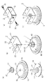
図1(a)に示す本発明の持出部材1は、屋根面に固定する第1部材1Aと、前記第1部材1Aの表面側の全外周を覆う第2部材1Bと、前記第1部材1A及び前記第2部材1Bを連結する第3部材1Cとからなる。
The take-out
前記第1部材1Aは、屋根面に防水材12を介して固定する固定部11と該固定部11に立設した縦杆13とを備える。
前記固定部11は、ビスやアンカーボルト等の固定具(図示せず)を用いて屋根面に固定されるものであり、図示実施例では、その挿着孔111が2箇所に設けられている。
図示実施例では、前記防水材12は、固定部11の裏面側に配されるシート状のシール材(ゴムシート又はシリコーンシート)であり、前記縦杆13は、ボルト材である。
The
The said fixing | fixed part 11 is fixed to a roof surface using fixing tools (not shown), such as a bis | screw and an anchor bolt, In the example of illustration, the insertion hole 111 is provided in two places. .
In the illustrated embodiment, the
前記第2部材1Bは、前記第1部材1Aを覆う被覆部14の外側に屋根面に防水材15を介して接地させる接地部16を周設し、前記被覆部14には前記縦杆13を挿通させる挿通孔141を設けている。
この第2部材1Bは、図示実施例では、平面視円形状(略ハット形状)に形成され、防水材15は、前記第1部材1Aに用いられた防水材12と同様にシート状のシール材(ゴムシート又はシリコーンシート)であり、前記挿通孔141は、前記縦杆13の直径より僅かに大きく形成されている。
The
In the illustrated embodiment, the
前記第3部材1Cは、前記第1部材1Aの前記縦杆13に取り付けて締着することにより、前記第2部材1Bを屋根面に圧着する部材であって、図示実施例では前記縦杆(ボルト材)13に螺合するナットである。
この第3部材1Cは、図示実施例では、防水材付きの座金1Dを介して前記縦杆(ボルト材)13に螺合しており、この第3部材1Cであるナットを締め付けることにより、前記第2部材1Bを屋根面に圧着する。
The
In the illustrated embodiment, the
これらの各部材から構成される持出部材1は、図1(b)に示すように3つの部材1A〜1C(防水材付きの座金1Dを含めると4つの部材)を一体的に組み付けた構成であって、図示するような受部材2を第3部材1Cの上部に取り付けることにより、後述する支持部材3の取り付けが容易となる。なお、図1(c)は、受部材2を第3部材1Cの上部に取り付けた状態を示す。
図示実施例の受部材2は、略矩形状の平板部21の前後端に縦片部22,22が形成される略U字状のピース材であり、平板部21の略中央には、前記縦杆13が貫通する孔211が設けられる。また、各縦片部22には、後述する支持部材3の取り付けに用いられる固定具30の取付孔221がそれぞれ2箇所に形成されている。
As shown in FIG. 1 (b), the take-out
The receiving
そして、これらの各部材から構成される持出部材1の設置施工について、図2を用いて説明する。
まず、図2の右手前側に示すように第1の工程として、屋根面に第1部材1Aを固定する。この図示実施例では屋根面は横葺き屋根であるから、予め横葺き外装材5の裏面側に水流れ方向に配設されている垂木41の位置を特定しておき、ビスである固定具17,17を固定部11の挿着孔111,111から打ち込んで垂木41に下端が達するように固定する。
次に、第2の工程として、第2部材1Bを被せるように配設するが、前記第1部材1Aの縦杆13が挿通孔141から突出するように配設する。
その後、第3の工程として、第2部材1Bから突出するボルト材である縦杆13に、ナットである第3部材1Cを取り付け、これを締め付けることにより、第2部材1Bが下方に押圧されてその接地部16が屋根面に圧着する。
なお、第3部材1Cの取付けに際し、防水材付きの座金1Dを併用した。
And the installation construction of the taking-out
First, as shown in the right front side of FIG. 2, as a first step, the
Next, as a second step, the
Thereafter, as a third step, the
In addition, when attaching the
その後、前記第3部材1Cの上方から前記構成の受部材2を臨ませ、前記縦杆13が孔211に貫通するように配し、ナット20を締着して固定した。この状態は、図2の略中央に示した。なお、前記受部材2を縦杆13に配した状態で第3部材1Cを取り付け締着するようにしてもよい。この場合、第3部材1Cがナット20を兼ねるものとなる。
前記受部材2の組み付けに際しては、各縦片部22が流れ方向に直交するように微調整して組み付ける。
そして、組み付けた受部材2に対し、図2の左奥に示すように長尺な支持部材3を取り付ける。
図示実施例の支持部材3は、上面部31の前後端に縦面部32,32が形成される逆U字状の長尺材であり、桁行き方向に長尺で、その幅寸法は前記受部材2の縦片部22,22間の間隔と略同一である。また、各縦面部32の下端は内側へ折曲されている。
したがって、支持部材3は、前記持出部材1に組み付けた受部材2の縦片部22,22間に嵌め付けるように配設すればよく、この状態で固定具30を受部材2の取付孔221から打ち込んで極めて容易に取り付けることができる。
なお、この図2における41は垂木を示すが、42は躯体(C型鋼)であり、43はその上に配設された下地材であり、44は垂木41,41間に配される木毛セメント板又は断熱材である。
このように持出部材1を垂木41などの支持部材に固定することにより、設置安定性が格段に向上するものとなる。このような効果は、躯体に直接的に取り付ける場合にも果たされ、後述する図3〜図7の各実施例においても、躯体もしくは躯体に直接又は間接的に取り付けられた垂木41等の支持部材に固定するようにしたため、それぞれ同様の効果が果たされる。
Thereafter, the receiving
When the receiving
And the elongate supporting
The
Therefore, the
Note that
By fixing the take-out
図3に示す実施例は、前記支持部材3に外設部材として太陽電池システム(太陽電池パネル8)を取り付けた例を示すものであり、桁行き方向に長尺な支持部材3に対して直交するように水流れ方向に連続する縦桟7aを固定具71にて取付け、この縦桟7a上に外設部材(外設構築物)として太陽エネルギー変換モジュール(太陽電池)81を一体的に備えるパネル8を固定した構成である。なお、前記縦桟7aについては、後述する図5に示される縦桟7cと同様に排水部材を兼ねる構成とする。
The embodiment shown in FIG. 3 shows an example in which a solar cell system (solar cell panel 8) is attached to the
図示実施例の屋根面(既設屋根)を構成する横葺き外装材5は、面板部51の水下側及び水上側に成形部52(水下側成形部),53(水上側成形部)を設けた構成であり、面板部51は、中央よりやや水上側で谷状に屈曲し、水下側近傍で山状に屈曲した略平坦状である。
水下側成形部52は、面板部51の水下縁を下方へ略鉛直状に曲げ(縦片部521)、その下端を水上側へ曲げ成形し、続いて上方へ略く字状に屈曲し(横片部522)、さらにその先端を表面側へ折り返した構成とした。
水上側成形部53は、面板部51から延在する端縁(延在部531)を表面側上方へ折り返し状に曲げ成形し、その上端を水下側下方へ折り曲げた構成とした。
そして、これらの水下側成形部52と水上側成形部53とは、敷設状態において係合する構成とした。
The side covering material 5 constituting the roof surface (existing roof) of the illustrated embodiment has molding parts 52 (water-side molding parts) and 53 (water-side molding parts) on the water side and water side of the
The
The water-
The water-
また、前記横葺き外装材5を保持する保持部材6Aは、一般に吊子と称される部材であって、この図示実施例に用いられる保持部材6Aは、横葺き外装材5の水上側成形部53(被保持部)を保持する保持部61と、定着片である固定部62とを有する構成である。上記の固定部62は、ハット型躯体である垂木41の上面部にビス621により固定されている。
In addition, the holding member 6A for holding the side covering member 5 is a member generally called a hanging member, and the holding member 6A used in the illustrated embodiment is a water-side molded part of the side covering member 5. This is a configuration having a holding portion 61 that holds 53 (held portion) and a fixing
なお、屋根面については、前述のとおりであるが、図示するように躯体(C型鋼)42上に下地材43が配設され、その上面に水流れ方向に沿うように垂木41が配され、該垂木41に跨るようにハット状の固定部材45を配し、この固定部材45を固着具46にて下地材43を通して躯体42に固定し、前記垂木41,41間には木毛セメント板又は断熱材44を取り付けている。
As for the roof surface, as described above, a
図示実施例の太陽電池パネル8は、表面側に透光材が配された太陽電池81と、その端縁を保持すると共に裏面側に中空のスペース部分を備えるフレーム材82,82とが一体的に取り付けられた構成である。
また、水流れ方向に隣接する太陽電池パネル8,8は、表面側の隙間に不定形のシール材83が充填され、その裏面側に配される断面略W字状のジョイント部材7bにて連結されている。
前記ジョイント部材7bは、連結部材と流水部材とを兼ねるものであって、流れ方向に配設されて排水部材を兼ねる縦桟7aと連絡されて雨水等を水下側へ流下させる役割も果たす。そして、樋状部分(流水部74)を形成する水下側の側面部72の上端が太陽電池パネル8の裏面を支持し、水上側の側面部は低く形成されている。そのため、水上側に配された太陽電池パネル8の裏面側に生じた結露水などはその裏面をつたって樋状部分に導かれる。また、樋状部分(流水部74)を形成する底面部の略中央から略垂直状に立ち上がる起立片部73は、太陽電池パネル8,8のフレーム材82,82間に配されるため、太陽電池パネル8,8の配設に際して取付位置を容易に定めることができる。
In the
The
The
このような構成を有する太陽電池パネル8の取付構造は、前述のように容易に設置した持出部材1に、受部材2を介して桁行き方向に取り付けた支持部材3に対し、外設部材として太陽電池パネル8を取り付けたものであって、取り付ける太陽電池パネル8の構成について全く制限されるものではないため、各種メーカー及び各種寸法、各種仕様の太陽電池パネルを適用することができ、極めて実用的価値が高いものである。
The mounting structure of the
図4に示す実施例は、前記支持部材3に既設屋根とほぼ同様の構成を有する改修屋根を構築する例を示すものであり、その下地(屋根面)構成についても前記下地面とほぼ同様の構造を有する。すなわちこの図示実施例では、桁行き方向に長尺な支持部材3に対して直交するように水流れ方向に沿うように垂木41が配され、該垂木41に跨るようにハット状の固定部材45を配し、この固定部材45を固着具47にて下地材43を通して支持部材3に固定し、前記垂木41,41間には木毛セメント板又は断熱材44を取り付けている。
すなわち前記既設の屋根面との違いは、垂木41を取り付ける固定部材45が躯体42ではなく支持部材3に固定されるだけであって、また下地材43が無いため、固着具47が前記図3の固着具46よりも短いものが用いられている。
The embodiment shown in FIG. 4 shows an example of constructing a modified roof having the same configuration as the existing roof on the
That is, the difference from the existing roof surface is that the fixing
このような構成を有する改修構造は、前述のように容易に設置した持出部材1に、受部材2を介して桁行き方向に取り付けた支持部材3に対し、新たな屋根構造を取り付けたものであって、取り付ける屋根構造は、図示するように既設屋根と全く同様の構成でもよいし、その構成について全く制限されるものではないため、各種メーカー及び各種寸法、各種仕様の屋根構造を適用することができ、極めて実用的価値が高いものである。
The renovation structure having such a configuration is a structure in which a new roof structure is attached to the
図5に示す実施例は、縦葺き外装構造である屋根面に、前記構成の持出部材1、受部材2、支持部材3をそれぞれ取り付け、この支持部材3に外設部材として前記図3における太陽電池パネル8と略同様の太陽電池パネル8'を取り付けた例を正面から見た状態を示す。
In the embodiment shown in FIG. 5, the carrying
図示実施例の屋根面(既設屋根)を構成する縦葺き外装材9aは、躯体42上に配された下地材43に適宜間隔にて取り付けられた保持部材6b,6b間に配設される。
この縦葺き外装材9aは、面板部91の左右の側縁に裏面側が開放する内側立上り部92,92を有し、その外側に排水溝93,93、さらにその外側に傾斜状に立ち上がる外側立上り部94,94を有し、この外側立上り部94の途中(高さの中程)に、保持部材6bの被嵌合部63に係合する略く字状の嵌合部941が形成される構成である。また、前記外側立上り部94,94の上方の構成については、左右非対称であり、左方側には、保持部材6bの中央起立部64の頂部に至る延在部が設けられ、右方側には、他方側(この場合、右側に隣接する縦葺き外装材9aの左方側の外側立上り部94)にオーバーハングする重合部95が設けられている。また、この重合部95には、嵌合部941の外側に係合する略く字状の係合部が設けられている。
The vertical
The vertical facing
また、前記保持部材6bは、下地材43に固定される固定部64から上方に側端起立部65、中央起立部66、側端起立部65が延在する構成であり、中央起立部64の上端は鏃状に形成され、その下方の左右に形成される隅部が被嵌合部63,63である。この保持部材6bはピース材であって、中央起立部66が形成されない固定部64からアンカーボルトである固着具67が打ち込まれ、下地材43を貫いて躯体42に至っている。
Further, the holding
そして、図示実施例の屋根面を構築するには、躯体42上に下地材43を配し、適宜間隔にて前記構成の保持部材6bを固着具67にて固定し、固定した保持部材6b,6b間に前記構成の縦葺き外装材9aを配設する。
縦葺き外装材9aの配設に際しては、まず、内側立上り部92の裏面に保持部材6bの側端起立部65が位置するように取り付ける。なお、縦葺き外装材9aの面板部91は、予め保持部材6b,6bの側端起立部65,65間よりも幅広に形成されているので、この状態で、縦葺き外装材9aの面板部91は、下方へ突出するように湾曲されて配設される。
次に、保持部材6bの中央起立部66と側端起立部65との間に、縦葺き外装材9aの排水溝93及び外側立上り部94が位置するように配し、嵌合部941を被嵌合部63に弾性的に嵌合させる。
さらに、左方側の外側立上り部94については、そのまま中央起立部66の右側に沿わせるが、右方側の外側立上り部94については、中央起立部66の他方側(右側)に延在するようにオーバーハングさせて係合させる。
In order to construct the roof surface of the illustrated embodiment, the
When arranging the vertical facing
Next, the
Further, the left-side outer rising
このように施工される縦葺き外装構造に対し、前記図2の手順と全く同様に持出部材1を設置する。
前記図2では、持出部材1の第1部材1Aは、ビスである垂木41に対して固着具17にて固定したが、この実施例では、躯体42に対してアンカーボルトである固着具17'にて固定する点が異なるだけであり、他の構成については全く同様であるから同一符号を付して説明を省略する。ピース状の受部材2を用いる点や横方向(桁行き方向)に連続する支持部材3を用いる点も同様である。
The take-out
In FIG. 2, the
そして、この図5における図示実施例では、前記図3の実施例とほぼ同様の太陽電池システム(太陽電池パネル8')を取り付けた。
この図5の太陽電池パネル8'は、表面側に透光材が配された太陽電池81と、その側縁を保持すると共に裏面側に中空のスペース部分を備えるフレーム材83,83とが一体的に取り付けられた構成である。
また、横方向に隣接する太陽電池パネル8',8'の表面側に跨るように化粧板材84が固定具85にて取り付けられ、その裏面側には、排水部材(排水部76)を兼ねる縦桟7cが配されて連結されている。
前記縦桟7cは、水流れ方向に連続する長尺材、又は定尺材を連結した構成であって、排水部材(排水部76)を兼ね、左右の脚片75,75の下端を固定具71,71にて支持部材3に取り付けられている。また、この縦桟7cの上方には、流水部材7dが固定され、排水部76に連絡するように横方向に配設されている。
なお、前記縦桟7cは、樋状の排水部76が支持部材3上に固定した左右の脚片75,75の下端より高いレベルに位置しており、この排水部76の略中央には太陽電池パネル8',8'を支持する台状の隆起部77が設けられ、前記化粧板材84を固定する固定具85もこの隆起部77の上面に固定されている。
このようにこの実施例における縦桟7c及び流水部材7dは、前記図3の実施例における縦桟7a及びジョイント部材7bに相当するものである。
In the illustrated embodiment in FIG. 5, a solar cell system (
In the
In addition, a
The
The
Thus, the
図6に示す実施例は、前記図5とほぼ同様の縦葺き外装材9bからなる縦葺き外装構造である屋根面に、前記構成の持出部材1、受部材2、支持部材3をそれぞれ取り付け、この支持部材3に外設部材として前記図3と全く同じ太陽電池パネル8を取り付けた例を示す。
したがって、この図6には、前記図3と同じ符号を付して説明を省略する。
この図6には、側断面を示したので、太陽電池パネル8と太陽電池パネル8'が異なる以外は、前記図5(正面図)の側断面構成とほぼ等しいものである。
In the embodiment shown in FIG. 6, the take-out
Therefore, the same reference numerals as those in FIG.
Since FIG. 6 shows a side cross-section, it is substantially the same as the side cross-sectional configuration of FIG. 5 (front view) except that the
図7に示す実施例は、前記図5とほぼ同様の縦葺き外装材9bからなる縦葺き外装構造である屋根面に、前記構成の持出部材1、受部材2、支持部材3をそれぞれ取り付け、この支持部材3に既設屋根と異なる縦葺き外装構造の改修屋根を構築する例を示す。
なお、この実施例では、側断面を示しているが、改修屋根の構成を詳しく示すため、正面から見た状態を付記している。
In the embodiment shown in FIG. 7, the take-out
In addition, in this Example, although the cross section is shown, in order to show the structure of a repaired roof in detail, the state seen from the front is added.
図示実施例における改修屋根は、前記構成の支持部材3上に保持部材(6c,6d)を固定し、該保持部材(6c,6d)に縦葺き外装材9c,9cの左右の側縁を保持させ、キャップ材9dを取り付けた構成である。
In the modified roof in the illustrated embodiment, the holding members (6c, 6d) are fixed on the
前記保持部材(6c,6d)は、略左右対称の部材であって、支持部材3に固定する略門型のタイトフレーム6cと、該タイトフレーム6cの略中央の横片に下方からボルトナットにて留め付けた受支材6dとからなる。
タイトフレーム6cは、例えば短幅の帯状鋼材を折り曲げ成形してなり、略中央の横片から左右に脚部を有し、各脚部の下端に下面が支持部材3と接する固定部である。
受支材6dは、略垂直状に起立する受支面を前後に有する側断面略U字状のピース材であり、各受支面の下方には左右に張り出した部分が形成され、その下方が前記外装材9cの第1嵌合部971が嵌合する被嵌合部68である。また、受支面の上縁を前後方向に折り曲げ、前記外装材9cの裏面を安定に保持できるようにしている。さらに、この受支面の略中央上端には、前記外装材9cの断面略U字状の第2嵌合部972を上方から嵌合可能な矩形状の溝部69が設けられている。
The holding members (6c, 6d) are substantially bilaterally symmetric members, and have a substantially gate-shaped
The
The receiving
前記保持部材(6c,6d)に保持させる縦葺き外装材9cは、略平坦状の面板部96の左右の側縁に左右対称の傾斜状の立ち上げ部97,97を有する構成であり、この立ち上げ部97の高さの途中には、後述する保持部材6cに嵌合状に取り付けるための第1嵌合部971が設けられ、該第1嵌合部971の上方に、受支材6dに支持される部分を介し、その先端には、受支材2Bの略中央上端に形成された溝部69に上方から嵌合させる断面略U字状の第2嵌合部972を有する構成である。
The
前記外装材9cと共に外装面を形成するキャップ9dは、左右方向に隣接する外装材9c,9cの外側立上り部97,97間に配設されるものであって、前記外装材9cと同様な素材から成形されるものであり、略傘状の化粧部98の左右の側縁に設けた折返し部99を前記外装材9cの第1嵌合部971の裏面に嵌合させて取り付けられる。
The
1 持出部材
1A 第1部材
1B 第2部材
1C 第3部材
1D 防水材付きの座金
11 固定部
12,15 防水材
13 縦杆
14 被覆部
141 挿通孔
16 接地部
2 受部材
3 支持部材
41 垂木
42 躯体
43 下地材
44 木毛セメント板又は断熱材
5 横葺き外装材
6A〜6 保持部材
7a 縦桟
7b ジョイント部材
7c 縦桟
7d 流水部材
8,8' 外設部材(太陽電池システム)
9a,9b,9c 縦葺き外装材
9d キャップ材
DESCRIPTION OF
9a, 9b, 9c
Claims (5)
前記第1部材は、屋根面に防水材を介して固定する固定部と該固定部に立設した縦杆とを備え、
前記第2部材は、前記第1部材を覆う被覆部の外側に屋根面に防水材を介して接地させる接地部を周設し、前記被覆部には前記縦杆を挿通させる挿通孔を設け、
前記第3部材は、前記縦杆に取り付けて締着することにより、前記第2部材を屋根面に圧着するものであることを特徴とする持出部材の設置構造。 Installation of a take-out member comprising a first member fixed to the roof surface, a second member covering the entire outer periphery on the surface side of the first member, and a third member connecting the first member and the second member Structure,
The first member includes a fixed portion that is fixed to the roof surface via a waterproof material, and a vertical shaft that is erected on the fixed portion,
The second member has a grounding portion that is grounded through a waterproof material on the roof surface outside the covering portion that covers the first member, and the covering portion is provided with an insertion hole through which the vertical gutter is inserted,
The installation structure of the take-out member, wherein the third member is attached to the downboard and fastened to crimp the second member to the roof surface.
屋根面に第1部材を固定する第1の工程と、
第2部材を被せるように配設する第2の工程と、
第2部材から突出する縦杆に、第3部材を取り付け、締め付ける第3の工程と、からなることを特徴とする持出部材の設置施工方法。 An installation method for constructing the installation structure according to claim 1 or 2,
A first step of fixing the first member to the roof surface;
A second step of arranging to cover the second member;
And a third step of attaching and tightening the third member to the vertical rod protruding from the second member.
Priority Applications (1)
| Application Number | Priority Date | Filing Date | Title |
|---|---|---|---|
| JP2009174335A JP2011026859A (en) | 2009-07-27 | 2009-07-27 | Installation structure for extended member, installation construction method therefor, fitting structure for external installation member using the same, and repairing structure |
Applications Claiming Priority (1)
| Application Number | Priority Date | Filing Date | Title |
|---|---|---|---|
| JP2009174335A JP2011026859A (en) | 2009-07-27 | 2009-07-27 | Installation structure for extended member, installation construction method therefor, fitting structure for external installation member using the same, and repairing structure |
Related Child Applications (1)
| Application Number | Title | Priority Date | Filing Date |
|---|---|---|---|
| JP2015070233A Division JP6298790B2 (en) | 2015-03-30 | 2015-03-30 | Installation structure of take-out member, its installation and construction method, and external member mounting structure and repair structure using the same |
Publications (1)
| Publication Number | Publication Date |
|---|---|
| JP2011026859A true JP2011026859A (en) | 2011-02-10 |
Family
ID=43635891
Family Applications (1)
| Application Number | Title | Priority Date | Filing Date |
|---|---|---|---|
| JP2009174335A Pending JP2011026859A (en) | 2009-07-27 | 2009-07-27 | Installation structure for extended member, installation construction method therefor, fitting structure for external installation member using the same, and repairing structure |
Country Status (1)
| Country | Link |
|---|---|
| JP (1) | JP2011026859A (en) |
Cited By (4)
| Publication number | Priority date | Publication date | Assignee | Title |
|---|---|---|---|---|
| JP2013067985A (en) * | 2011-09-22 | 2013-04-18 | Daiwa House Industry Co Ltd | Stand support material and stand support structure |
| JP2015151804A (en) * | 2014-02-17 | 2015-08-24 | 旭化成ホームズ株式会社 | Auxiliary fixing tool and fixing structure |
| CN108166659A (en) * | 2017-12-28 | 2018-06-15 | 山东雅百特科技有限公司 | A kind of safety-type, wind resistance lifts metal Roof construction system and its mounting process |
| CN113585770A (en) * | 2021-09-02 | 2021-11-02 | 苏州凯伦高分子新材料科技有限公司 | Photovoltaic installation method for light steel roof |
Citations (3)
| Publication number | Priority date | Publication date | Assignee | Title |
|---|---|---|---|---|
| JPH09317111A (en) * | 1996-06-03 | 1997-12-09 | Eco Tec Syst Center:Kk | Device and method for attachment of rooftop equipment for western-style flat roof |
| JP2000120236A (en) * | 1998-10-12 | 2000-04-25 | Taisei Corp | Waterproofing work method for member penetrated through waterproof layer using cap |
| JP2006052529A (en) * | 2004-08-09 | 2006-02-23 | Kyocera Corp | System utilizing sunlight |
-
2009
- 2009-07-27 JP JP2009174335A patent/JP2011026859A/en active Pending
Patent Citations (3)
| Publication number | Priority date | Publication date | Assignee | Title |
|---|---|---|---|---|
| JPH09317111A (en) * | 1996-06-03 | 1997-12-09 | Eco Tec Syst Center:Kk | Device and method for attachment of rooftop equipment for western-style flat roof |
| JP2000120236A (en) * | 1998-10-12 | 2000-04-25 | Taisei Corp | Waterproofing work method for member penetrated through waterproof layer using cap |
| JP2006052529A (en) * | 2004-08-09 | 2006-02-23 | Kyocera Corp | System utilizing sunlight |
Cited By (4)
| Publication number | Priority date | Publication date | Assignee | Title |
|---|---|---|---|---|
| JP2013067985A (en) * | 2011-09-22 | 2013-04-18 | Daiwa House Industry Co Ltd | Stand support material and stand support structure |
| JP2015151804A (en) * | 2014-02-17 | 2015-08-24 | 旭化成ホームズ株式会社 | Auxiliary fixing tool and fixing structure |
| CN108166659A (en) * | 2017-12-28 | 2018-06-15 | 山东雅百特科技有限公司 | A kind of safety-type, wind resistance lifts metal Roof construction system and its mounting process |
| CN113585770A (en) * | 2021-09-02 | 2021-11-02 | 苏州凯伦高分子新材料科技有限公司 | Photovoltaic installation method for light steel roof |
Similar Documents
| Publication | Publication Date | Title |
|---|---|---|
| JP4679482B2 (en) | Solar cell module fixing member and solar cell module fixing structure | |
| JP4160035B2 (en) | Solar cell module mounting structure | |
| JP2008231914A (en) | Installation structure of solar battery module | |
| JP5788290B2 (en) | Roof fixing device | |
| JP2011026859A (en) | Installation structure for extended member, installation construction method therefor, fitting structure for external installation member using the same, and repairing structure | |
| JP5404354B2 (en) | Draining structure for solar cell module | |
| JP6298790B2 (en) | Installation structure of take-out member, its installation and construction method, and external member mounting structure and repair structure using the same | |
| JP5366057B2 (en) | Installation structure for take-out member, attachment structure for external member, and repair structure | |
| JP2010163815A (en) | Installation structure of solar cell module | |
| JP5479033B2 (en) | Roof structure | |
| JP5666325B2 (en) | Roof fixing device | |
| JP2011074581A (en) | Installation structure and installation method for corbel member, and mounting structure of external member using the same | |
| JP2011122402A (en) | Planar supporting tile for solar panel, and method for installing solar panel using the same | |
| JP5465196B2 (en) | Equipment fixed waterproof structure | |
| JP5674889B1 (en) | Installation structure of solar cell module | |
| JP5648995B2 (en) | Mounting structure of support frame and exterior structure | |
| JP5869273B2 (en) | Mounting method of base support | |
| JP5129967B2 (en) | Roof structure | |
| JP2002371678A (en) | Roof tile with solar battery | |
| JP5968115B2 (en) | Equipment fixing device | |
| JP5836199B2 (en) | Support bracket | |
| JP5207556B2 (en) | External member mounting structure | |
| JP4509949B2 (en) | Exterior structure | |
| JP5721870B2 (en) | Equipment fixed waterproof structure | |
| JP3051137U (en) | Metal fitting structure for solar device |
Legal Events
| Date | Code | Title | Description |
|---|---|---|---|
| A621 | Written request for application examination |
Free format text: JAPANESE INTERMEDIATE CODE: A621 Effective date: 20110803 |
|
| A977 | Report on retrieval |
Free format text: JAPANESE INTERMEDIATE CODE: A971007 Effective date: 20121221 |
|
| A131 | Notification of reasons for refusal |
Free format text: JAPANESE INTERMEDIATE CODE: A131 Effective date: 20130108 |
|
| A02 | Decision of refusal |
Free format text: JAPANESE INTERMEDIATE CODE: A02 Effective date: 20131203 |