JP2011019383A - Motor - Google Patents
Motor Download PDFInfo
- Publication number
- JP2011019383A JP2011019383A JP2009285587A JP2009285587A JP2011019383A JP 2011019383 A JP2011019383 A JP 2011019383A JP 2009285587 A JP2009285587 A JP 2009285587A JP 2009285587 A JP2009285587 A JP 2009285587A JP 2011019383 A JP2011019383 A JP 2011019383A
- Authority
- JP
- Japan
- Prior art keywords
- hub
- stator
- rotor
- motor
- rotating body
- Prior art date
- Legal status (The legal status is an assumption and is not a legal conclusion. Google has not performed a legal analysis and makes no representation as to the accuracy of the status listed.)
- Granted
Links
Images


Classifications
-
- H—ELECTRICITY
- H02—GENERATION; CONVERSION OR DISTRIBUTION OF ELECTRIC POWER
- H02K—DYNAMO-ELECTRIC MACHINES
- H02K1/00—Details of the magnetic circuit
- H02K1/06—Details of the magnetic circuit characterised by the shape, form or construction
- H02K1/22—Rotating parts of the magnetic circuit
- H02K1/28—Means for mounting or fastening rotating magnetic parts on to, or to, the rotor structures
- H02K1/30—Means for mounting or fastening rotating magnetic parts on to, or to, the rotor structures using intermediate parts, e.g. spiders
-
- H—ELECTRICITY
- H02—GENERATION; CONVERSION OR DISTRIBUTION OF ELECTRIC POWER
- H02K—DYNAMO-ELECTRIC MACHINES
- H02K5/00—Casings; Enclosures; Supports
- H02K5/04—Casings or enclosures characterised by the shape, form or construction thereof
- H02K5/16—Means for supporting bearings, e.g. insulating supports or means for fitting bearings in the bearing-shields
-
- G—PHYSICS
- G11—INFORMATION STORAGE
- G11B—INFORMATION STORAGE BASED ON RELATIVE MOVEMENT BETWEEN RECORD CARRIER AND TRANSDUCER
- G11B19/00—Driving, starting, stopping record carriers not specifically of filamentary or web form, or of supports therefor; Control thereof; Control of operating function ; Driving both disc and head
- G11B19/20—Driving; Starting; Stopping; Control thereof
- G11B19/2009—Turntables, hubs and motors for disk drives; Mounting of motors in the drive
-
- H—ELECTRICITY
- H02—GENERATION; CONVERSION OR DISTRIBUTION OF ELECTRIC POWER
- H02K—DYNAMO-ELECTRIC MACHINES
- H02K5/00—Casings; Enclosures; Supports
- H02K5/24—Casings; Enclosures; Supports specially adapted for suppression or reduction of noise or vibrations
Abstract
Description
本発明はモータに関する。 The present invention relates to a motor.
一般的にスピンドルモータ(Spindle motor)はコンピュータ用ドライブなどの、精密な回転装置を必要とする電子製品に広く採用されている。スピンドルモータは、小型でありながら高速回転が可能であり、精密制御が容易であり、電力消費が少ないなどの様々な長所があり、今後その使用が増えることが見込まれている。 Generally, a spindle motor is widely used in electronic products that require a precise rotating device such as a computer drive. The spindle motor has various advantages such as being compact and capable of high-speed rotation, easy precision control and low power consumption, and its use is expected to increase in the future.
このようなスピンドルモータは、回転するロータ(rotor)と、ロータの回転運動を支持するステータ(stator)と、を含むように形成されている。そして、ロータは、一般的に回転軸と、回転軸と結合している回転体と、で形成されている。 Such a spindle motor is formed to include a rotating rotor and a stator that supports the rotational movement of the rotor. The rotor is generally formed of a rotating shaft and a rotating body coupled to the rotating shaft.
しかし、モータのスリム化の傾向に伴って、回転軸と回転体が結合される領域が小さくなり、これによって回転時にロータの安定性が低下するという問題が発生している。すなわち、モータのスリム化により、回転体と結合する回転軸が短くなり、回転体を支持する回転軸の面積が減少する。このため、回転体と回転軸の結合強度が低下して回転の際に発生する振動に対する抵抗力が弱まり、回転時のロータの安定性が低下することになる。 However, with the trend toward slimming motors, the area where the rotating shaft and the rotating body are coupled to each other becomes smaller, which causes a problem that the stability of the rotor is lowered during rotation. That is, due to the slimming of the motor, the rotating shaft coupled to the rotating body is shortened, and the area of the rotating shaft that supports the rotating body is reduced. For this reason, the coupling strength between the rotating body and the rotating shaft is lowered, the resistance to vibration generated during rotation is weakened, and the stability of the rotor during rotation is lowered.
こうした従来技術の問題点に鑑み、本発明は、ロータの回転時に安定性の確保されたモータを提供することを目的とする。 In view of the problems of the prior art, an object of the present invention is to provide a motor that ensures stability when the rotor rotates.
本発明の一実施態様によれば、ステータ及びステータに支持されて回転するロータを含むモータにおいて、ロータは、ステータに回転可能に支持される回転軸と、回転軸と一体に回転する回転体と、回転軸と回転体との間に介在するリング状のボディを備え、該ボディに、回転体と結合するボディの外周面を延長した突出部が備えられたハブと、を含むことを特徴とするモータが提供される。 According to one embodiment of the present invention, in a motor including a stator and a rotor that is supported by the stator and rotates, the rotor includes a rotating shaft that is rotatably supported by the stator, and a rotating body that rotates integrally with the rotating shaft. A ring-shaped body interposed between the rotating shaft and the rotating body, and a hub provided with a projecting portion extending from the outer peripheral surface of the body coupled to the rotating body. A motor is provided.
突出部は、ステータに向かって突出していてよい。 The protruding portion may protrude toward the stator.
回転体は、突出部を支持する支持段差部を含むことができる。 The rotating body can include a support step portion that supports the protrusion.
ハブは、回転軸と結合する楔部をさらに含むことができる。 The hub may further include a wedge portion that is coupled to the rotation shaft.
楔部はハブの内縁の部分に形成され、回転軸は楔部に対応して楔状に凹んだ結合段差部を含むことができる。 The wedge portion is formed at an inner edge portion of the hub, and the rotation shaft may include a coupling step portion that is recessed in a wedge shape corresponding to the wedge portion.
ハブのステータに向かう面には流体溝が形成されていてよい。 A fluid groove may be formed on a surface of the hub facing the stator.
流体溝は、外径側に向かって傾斜させることができる。 The fluid groove can be inclined toward the outer diameter side.
流体溝は、外径側に傾斜した辺を含む三角形の断面を有することができる。 The fluid groove may have a triangular cross section including a side inclined toward the outer diameter side.
本発明によれば、回転軸と回転体との結合強度が向上して、ロータの回転時に安定性を確保することができる。また、モータのオイルの飛散を防止し、空気抵抗を低減することができる。 According to the present invention, the coupling strength between the rotating shaft and the rotating body is improved, and stability can be ensured when the rotor rotates. In addition, the oil of the motor can be prevented from scattering and the air resistance can be reduced.
なお、上記の発明の概要は、本発明の必要な特徴の全てを列挙したものではない。また、これらの特徴群のサブコンビネーションもまた、発明となり得る。 The above summary of the invention does not enumerate all necessary features of the present invention. Also, a sub-combination of these feature groups can also be an invention.
本発明は、多様な変更を加えることができ、様々な実施例を有することができるが、本明細書では特定の実施例を図面に例示し、詳細に説明する。しかし、これは本発明を特定の実施例に限定するものではなく、本発明は、本発明の思想及び技術範囲に含まれるあらゆる変更、均等物及び代替物を含むものとして理解されるべきである。本発明を説明するに当たって、関係する公知技術についての具体的な説明が本発明の要旨をかえって不明瞭にすると判断される場合は、その詳細な説明を省略する。 While the invention is susceptible to various modifications, and may have various embodiments, specific embodiments are illustrated in the drawings and are described in detail herein. However, this is not to limit the invention to the specific embodiments, and the invention should be understood as including all modifications, equivalents and alternatives that fall within the spirit and scope of the invention. . In the description of the present invention, when it is determined that a specific description of a related known technique is obscured by changing the gist of the present invention, a detailed description thereof will be omitted.
以下に、本発明の実施例を添付図面に基づいて詳細に説明する。 Embodiments of the present invention will be described below in detail with reference to the accompanying drawings.
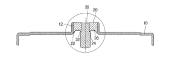
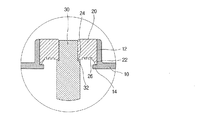
図1は、本発明の一実施例によるモータを示す断面図であり、図2は、本発明の一実施例によるモータのロータを示す断面図である。 FIG. 1 is a cross-sectional view illustrating a motor according to an embodiment of the present invention, and FIG. 2 is a cross-sectional view illustrating a rotor of a motor according to an embodiment of the present invention.
本発明の一実施例によるモータは、回転軸30、回転体10、及びハブ20を含むロータと、ロータを回転可能に支持するステータ40と、を含んでいる。
A motor according to an embodiment of the present invention includes a rotor including a rotating
一般的にモータは、ロータと、ロータの回転運動を支持するステータとを含むように形成されている。具体的には、ロータとしてはシャフト、ロータケースなどの形態のものがあり、ステータとしてはシャフトを回転可能に支持するハウジング、電磁石などの形態のものがある。 Generally, the motor is formed to include a rotor and a stator that supports the rotational motion of the rotor. Specifically, the rotor has a form such as a shaft and a rotor case, and the stator has a form such as a housing and an electromagnet that rotatably support the shaft.
本発明の一実施例によるモータは、図1に示すように、回転軸30、ロータケース、及びハブ20を含んでいる。
As shown in FIG. 1, the motor according to an embodiment of the present invention includes a
回転軸30はロータの回転の中心軸であって、ロータの回転時にロータ全体を支える部分である。このために、回転軸30はステータ40に回転可能に支持されている。
The rotating
本実施例の回転軸30は、一部分がステータ40のハウジング42に挿入されて支持されている。そして、回転軸30とハウジング42との間にはベアリング44が介在し回転軸30の回転を可能としている。
A part of the rotating
回転体10は、回転軸30と一体になって、回転軸30と共に回転する部分である。このために、後述するハブ20との結合により回転軸30に連結されている。
The rotating
本実施例の回転体10はロータケースであって、中央部にはハブ20と結合できるように貫通孔12が形成されている。
The rotating
ハブ20は回転軸30と回転体10とを一体化させる部分であって、回転軸30と回転体10との間に介在しているリング状のボディを備えている。ここで、ハブ20は、回転軸30に結合する部分だけ厚く形成でき、それによって、回転軸30と強固に結合するように回転軸30との結合領域の大きさを広くする役割を果たすことができる。
The
特に、本実施例におけるハブ20は、ハブ20と回転体10との結合強度を高めるために、回転体10と結合するボディの外周面を延長した突出部22を備えている。すなわち、ハブ20の外周に沿って、回転体10と結合するハブ20の外周面の面積を拡大する突出部22が形成されている。
In particular, the
これにより、回転軸30と回転体10とを、直接結合する場合に比較して、高い結合強度で結合することができる。したがって、ロータの回転時に振動に対する抵抗力が強化されてロータの回転安定性が向上する。
Thereby, compared with the case where the rotating
ここで、突出部22はステータ40に向かって突出しているため、スリム化されたモータでもハブ20と回転体10との結合領域を最大限に確保することができる。
Here, since the protruding
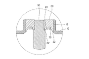
また、ハブ20と回転体10との結合強度をさらに高めるために、図3に示すように、突出部22を支持する支持段差部14を回転体10に形成可能である。
Further, in order to further increase the coupling strength between the
また、ハブ20と回転軸30との結合をさらに強固にするために、ハブ20は回転軸30と結合する楔部24をさらに含むことができる。具体的には、本実施例の楔部24は、回転軸30と結合するハブ20の内縁の部分に形成されている。そして、回転軸30には、楔部24が結合されるように、楔部24に対応して楔状に凹んだ結合段差部32が形成されている。
In order to further strengthen the coupling between the
一方、ハブ20には、ロータの回転の際の空気抵抗の低減や、オイル飛散の防止のために、ステータ40に面する面に流体溝26を形成可能である。
On the other hand, in the
図4から図7は、本発明の実施例によるハブ20における流体溝26を示す断面図である。
4 to 7 are sectional views showing the
ロータが高速回転するほど回転体10は空気抵抗を大きく受ける。特に、回転体10の表面で空気流の剥離が発生すると、回転体10の空気抵抗が大きく増加してロータの振動が激しくなる。このような空気流の剥離現象を防止するために、図4に示すように、ハブ20に流体溝26を多数形成して小さな乱流を発生させる。流体溝26によって発生した小さな乱流によって、空気流動が円滑になり、回転体10の表面で空気流動の剥離現象が発生するのが抑制される。このとき、図4及び図5に示すように、流体溝26の幅と深さはモータの作動回転数及び回転体10の直径などの設計仕様に応じて多様に変えることができる。
As the rotor rotates at a higher speed, the rotating
また、流体溝26はオイルの飛散を防止する役割も果たす。この場合には、図6に示すように、流体溝26を外径側に向かって傾斜するように形成することができる。具体的には、本実施例のハブ20における流体溝26は、外径側に傾斜した辺を含む三角形の断面を有している。
The
これにより、ロータの回転時に、遠心力により回転中心から外側に移動していくオイルが、傾斜した流体溝26に流入し、運動エネルギーを失って落ち込む。したがって、ロータの回転時に、オイルが回転体10の外部に流出され飛散されることを防止できる。このとき、図7に示すように、流体溝26の内径側端だけでなく、外径側端も傾斜するように形成することで、オイル飛散の防止効果をより向上させることができる。
As a result, when the rotor rotates, the oil moving outward from the center of rotation by centrifugal force flows into the
以上、本発明を実施例を用いて説明したが、本発明の技術的範囲は上記の実施例の記載の範囲には限定されない。上記実施例に、多様な変更または改良を加えることが可能であることが当業者に明らかである。その様な変更または改良を加えた形態も本発明の技術的範囲に含まれ得ることが、特許請求の範囲の記載から明らかである。 As mentioned above, although this invention was demonstrated using the Example, the technical scope of this invention is not limited to the description range of said Example. It will be apparent to those skilled in the art that various modifications or improvements can be made to the above-described embodiments. It is apparent from the scope of the claims that the embodiments added with such changes or improvements can be included in the technical scope of the present invention.
10 回転体
14 支持段差部
20 ハブ
22 突出部
24 楔部
26 流体溝
30 回転軸
32 結合段差部
40 ステータ
42 ハウジング
44 ベアリング
DESCRIPTION OF
Claims (8)
前記ロータは、
前記ステータに回転可能に支持される回転軸と、
前記回転軸と一体に回転する回転体と、
前記回転軸と前記回転体との間に介在するリング状のボディを備え、該ボディに、前記回転体と結合する前記ボディの外周面を延長した突出部が備えられているハブと、
を含むことを特徴とするモータ。 In a motor including a stator and a rotor that is supported by the stator and rotates,
The rotor is
A rotating shaft rotatably supported by the stator;
A rotating body that rotates integrally with the rotating shaft;
A hub having a ring-shaped body interposed between the rotating shaft and the rotating body, the body including a protrusion extending from an outer peripheral surface of the body coupled to the rotating body;
Including a motor.
前記回転軸は前記楔部に対応して楔状に凹んだ結合段差部を含むことを特徴とする請求項4に記載のモータ。 The wedge portion is formed at an inner edge portion of the hub,
The motor according to claim 4, wherein the rotation shaft includes a coupling step portion that is recessed in a wedge shape corresponding to the wedge portion.
Applications Claiming Priority (2)
| Application Number | Priority Date | Filing Date | Title |
|---|---|---|---|
| KR10-2009-0063088 | 2009-07-10 | ||
| KR1020090063088A KR101039851B1 (en) | 2009-07-10 | 2009-07-10 | motor |
Publications (2)
| Publication Number | Publication Date |
|---|---|
| JP2011019383A true JP2011019383A (en) | 2011-01-27 |
| JP5048047B2 JP5048047B2 (en) | 2012-10-17 |
Family
ID=43426927
Family Applications (1)
| Application Number | Title | Priority Date | Filing Date |
|---|---|---|---|
| JP2009285587A Expired - Fee Related JP5048047B2 (en) | 2009-07-10 | 2009-12-16 | motor |
Country Status (3)
| Country | Link |
|---|---|
| US (1) | US7932654B2 (en) |
| JP (1) | JP5048047B2 (en) |
| KR (1) | KR101039851B1 (en) |
Cited By (2)
| Publication number | Priority date | Publication date | Assignee | Title |
|---|---|---|---|---|
| JP2012254000A (en) * | 2011-06-03 | 2012-12-20 | Samsung Electro-Mechanics Co Ltd | Spindle motor |
| WO2016084354A1 (en) * | 2014-11-27 | 2016-06-02 | パナソニックIpマネジメント株式会社 | Electric motor, and refrigeration apparatus provided with electric motor |
Families Citing this family (2)
| Publication number | Priority date | Publication date | Assignee | Title |
|---|---|---|---|---|
| KR101020798B1 (en) * | 2008-12-03 | 2011-03-09 | 엘지이노텍 주식회사 | Spindle motor |
| KR20130051804A (en) * | 2011-11-10 | 2013-05-21 | 삼성전기주식회사 | Spindle motor |
Citations (3)
| Publication number | Priority date | Publication date | Assignee | Title |
|---|---|---|---|---|
| JP2003174748A (en) * | 2001-12-04 | 2003-06-20 | Hitachi Ltd | Disc drive motor for magnetic disc device |
| JP2005033897A (en) * | 2003-07-10 | 2005-02-03 | Mitsubishi Electric Corp | Rotary drive device |
| JP2007282374A (en) * | 2006-04-06 | 2007-10-25 | Nippon Densan Corp | Rotor component, motor and recording disk drive |
Family Cites Families (7)
| Publication number | Priority date | Publication date | Assignee | Title |
|---|---|---|---|---|
| JP3013960B2 (en) * | 1993-08-13 | 2000-02-28 | 株式会社三協精機製作所 | Disk drive motor |
| KR100316098B1 (en) | 1997-06-20 | 2002-11-08 | 삼성전기주식회사 | Structure for preventing oil leakage of spindle motor using fluid dynamic bearing |
| JP4260953B2 (en) * | 1998-12-14 | 2009-04-30 | 日本電産株式会社 | Spindle motor |
| TW420347U (en) * | 1999-01-11 | 2001-01-21 | Sunonwealth Electr Mach Ind Co | Transfer system structure of main axis motor for CD-ROM drive |
| KR100377611B1 (en) * | 1999-03-17 | 2003-03-26 | 가부시기가이샤 산교세이기 세이사꾸쇼 | Small size motor |
| US6704038B2 (en) * | 2000-09-27 | 2004-03-09 | Canon Seiki Kabushiki Kaisha | Light deflecting apparatus |
| KR101198612B1 (en) * | 2006-08-07 | 2012-11-07 | 엘지이노텍 주식회사 | Spindle motor |
-
2009
- 2009-07-10 KR KR1020090063088A patent/KR101039851B1/en not_active IP Right Cessation
- 2009-12-09 US US12/634,175 patent/US7932654B2/en not_active Expired - Fee Related
- 2009-12-16 JP JP2009285587A patent/JP5048047B2/en not_active Expired - Fee Related
Patent Citations (3)
| Publication number | Priority date | Publication date | Assignee | Title |
|---|---|---|---|---|
| JP2003174748A (en) * | 2001-12-04 | 2003-06-20 | Hitachi Ltd | Disc drive motor for magnetic disc device |
| JP2005033897A (en) * | 2003-07-10 | 2005-02-03 | Mitsubishi Electric Corp | Rotary drive device |
| JP2007282374A (en) * | 2006-04-06 | 2007-10-25 | Nippon Densan Corp | Rotor component, motor and recording disk drive |
Cited By (3)
| Publication number | Priority date | Publication date | Assignee | Title |
|---|---|---|---|---|
| JP2012254000A (en) * | 2011-06-03 | 2012-12-20 | Samsung Electro-Mechanics Co Ltd | Spindle motor |
| KR101512536B1 (en) * | 2011-06-03 | 2015-04-16 | 삼성전기주식회사 | Spindle motor |
| WO2016084354A1 (en) * | 2014-11-27 | 2016-06-02 | パナソニックIpマネジメント株式会社 | Electric motor, and refrigeration apparatus provided with electric motor |
Also Published As
| Publication number | Publication date |
|---|---|
| KR101039851B1 (en) | 2011-06-09 |
| US7932654B2 (en) | 2011-04-26 |
| KR20110005495A (en) | 2011-01-18 |
| JP5048047B2 (en) | 2012-10-17 |
| US20110006630A1 (en) | 2011-01-13 |
Similar Documents
| Publication | Publication Date | Title |
|---|---|---|
| JP5223137B2 (en) | Spindle motor and disk driver having the same | |
| JP5048047B2 (en) | motor | |
| JP5630143B2 (en) | Centrifugal fan and self-propelled robot equipped with centrifugal fan | |
| JP2016044673A (en) | Dynamic pressure bearing pump | |
| JP2015095962A (en) | Rotary machine | |
| JP2013155868A (en) | Spindle motor | |
| JP2014013072A (en) | Hydrodynamic bearing assembly and spindle motor having the same | |
| KR101444554B1 (en) | Hydrodynamic bearing assembly and spindle motor having the same | |
| US7517153B2 (en) | Fluid dynamic bearing system | |
| JP2016044674A (en) | Dynamic pressure bearing pump | |
| JP2015143576A (en) | Hydrodynamic bearing apparatus and spindle motor having same | |
| JP2012180810A (en) | Air blowing device | |
| KR101052851B1 (en) | motor | |
| JP4485379B2 (en) | Bearing and blood pump | |
| KR101071922B1 (en) | motor | |
| JP2013185706A (en) | Fluid dynamic pressure bearing assembly and motor including the same | |
| JP5498999B2 (en) | Spindle motor | |
| JP2009174414A (en) | Axial flow fan | |
| KR101095196B1 (en) | Spindle Motor | |
| JP2013118810A (en) | Spindle motor | |
| JP3798585B2 (en) | Hydrodynamic fluid bearing device and electric motor | |
| JP2007325329A (en) | Axial gap type motor and fuel pump | |
| CN207701454U (en) | Centrifugal pump | |
| JP2018019549A (en) | Rotary electric machine | |
| WO2016026364A1 (en) | Rotating component driven by electric motor, electric motor and fan |
Legal Events
| Date | Code | Title | Description |
|---|---|---|---|
| A131 | Notification of reasons for refusal |
Free format text: JAPANESE INTERMEDIATE CODE: A131 Effective date: 20120313 |
|
| A521 | Request for written amendment filed |
Free format text: JAPANESE INTERMEDIATE CODE: A523 Effective date: 20120530 |
|
| TRDD | Decision of grant or rejection written | ||
| A01 | Written decision to grant a patent or to grant a registration (utility model) |
Free format text: JAPANESE INTERMEDIATE CODE: A01 Effective date: 20120619 |
|
| A01 | Written decision to grant a patent or to grant a registration (utility model) |
Free format text: JAPANESE INTERMEDIATE CODE: A01 |
|
| A61 | First payment of annual fees (during grant procedure) |
Free format text: JAPANESE INTERMEDIATE CODE: A61 Effective date: 20120718 |
|
| FPAY | Renewal fee payment (event date is renewal date of database) |
Free format text: PAYMENT UNTIL: 20150727 Year of fee payment: 3 |
|
| R150 | Certificate of patent or registration of utility model |
Free format text: JAPANESE INTERMEDIATE CODE: R150 |
|
| LAPS | Cancellation because of no payment of annual fees |